snubsmart system information - rig safety. made...
TRANSCRIPT
Snubsmart System Information
V 1.0 June 11, 2015

2
Table of Contents
Display Panel ................................................................................................................. 3
Power Disconnect ......................................................................................................... 5
Pneumatic Override ...................................................................................................... 7
Foot Pedal Transducer ................................................................................................. 9
BOP Ram Sensor......................................................................................................... 11
LED Indicator ............................................................................................................... 13
Warning Station ........................................................................................................... 15
Pressure Sensor .......................................................................................................... 17
Commissioning, Testing and Training ...................................................................... 19
3
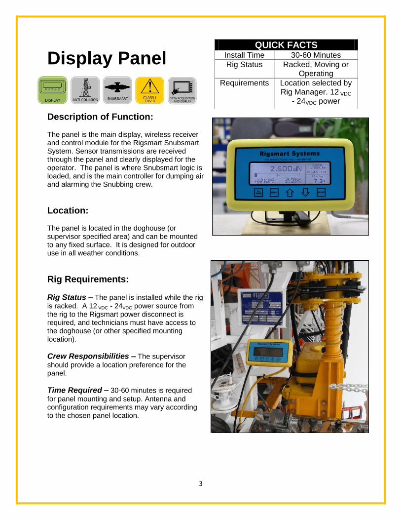
Display Panel
Description of Function: The panel is the main display, wireless receiver and control module for the Rigsmart Snubsmart System. Sensor transmissions are received through the panel and clearly displayed for the operator. The panel is where Snubsmart logic is loaded, and is the main controller for dumping air and alarming the Snubbing crew.
Location: The panel is located in the doghouse (or supervisor specified area) and can be mounted to any fixed surface. It is designed for outdoor use in all weather conditions.
Rig Requirements:
Rig Status – The panel is installed while the rig
is racked. A 12 VDC - 24VDC power source from the rig to the Rigsmart power disconnect is required, and technicians must have access to the doghouse (or other specified mounting location).
Crew Responsibilities – The supervisor
should provide a location preference for the panel.
Time Required – 30-60 minutes is required
for panel mounting and setup. Antenna and configuration requirements may vary according to the chosen panel location.
QUICK FACTS Install Time 30-60 Minutes
Rig Status Racked, Moving or Operating
Requirements Location selected by Rig Manager. 12 VDC
- 24VDC power

4
Display Panel Data Sheet
Overview
The main display, wireless receiver and control module for the Rigsmart Snubsmart System. Sensor transmissions are received through this panel and are clearly displayed for the operator. The Panel is also where Snubsmart logic is loaded, and is the main controller for dumping air before a collision occurs, and alarming the Snubbing crew. The panel is typically mounted in the doghouse.
Operating time 100% (continuous duty) Voltage type 12-24 VDC, 7.5A normal operating range (can accept 11-32 VDC) Operating temperature -40°C to +60°C Operating Frequency Range 900-928 MHz in North America 868-870 MHz in Europe Material Body material – Ultramid 8333G Hi-Polyamide 6 Seals – ROHS compliant silicon rubber, 60 durometer shore-A, compound # SIM40160 Connection Woodhead, bulgin or amphenol Mounting options Bolt on bracket Hazardous locations Class 1 Division 2 Ex nA IIB+H2 T4 Certified to: IEC CAN/CSA E60079-15:02 Environmental Ingress Protection IP67 Application Drilling rigs, Service rigs, Snubbing units
*Information subject to change without notice. Consult the
factory for the most current data and part numbers.*
Rigsmart Systems, Inc. 4908 97 St. Edmonton, AB T6L 4B2 Ph: 780.438.9475 Email: [email protected]

5
Power Disconnect
Description of Function: The Power Disconnect is the main on/off switch for the Rigsmart System. The box requires a 24 VDC power source, either provided directly from the customer or from a power converter box provided by Rigsmart Systems.
Location: The box is located in the doghouse (or other specified location) and can be mounted to any fixed surface. It is designed for outdoor use in all weather conditions.
Rig Requirements:
Rig Status – The panel is installed while the rig is racked.
A 24VDC power source from the rig to the Rigsmart power disconnect is required, and technicians must have access to the doghouse.
Crew Responsibilities – The Supervisor should
provide a location preference for the power disconnect.
Time Required – 15 minutes is required for mounting
and setup. Configuration requirements may vary according to the chosen panel location.
QUICK FACTS Install Time 15 Minutes
Rig Status Racked
Requirements Location selected by Supervisor. 24VDC
power

6
Rigsmart Systems, Inc. 4908 97 St. Edmonton, AB T6L 4B2 Ph: 780.438.9475 Email: [email protected]
Power Supply Data Sheet
Overview The Rigsmart Power Supply Box runs on a standard 120 VAC – 240 VAC source provided by the customer, and outputs 24 VDC for the use of the Rigsmart System components. Operating time 100% (continuous duty) Voltage type Input: 120 – 240 VAC Output: 12 or 24 VDC Operating temperature -40°C to +60°C Construction - 16 gauge steel body and cover - Welded seams without knockouts or holes - Seamless poured-in place gasket - Door includes a quarter turn slot for added safety Connection Bulgin Mounting options Bolt on bracket Hazardous locations Ex II 3 G Ex nA nC IIC T4 Gc TÜV 11 ATEX 079480 X Ex nA nC IIC T4 Gc IECEx TUN 11.0007X Environmental Ingress Protection IP67 Application Drilling rigs, Service rigs, Snubbing units
*Information subject to change without notice. Consult the
factory for the most current data and part numbers.*
7
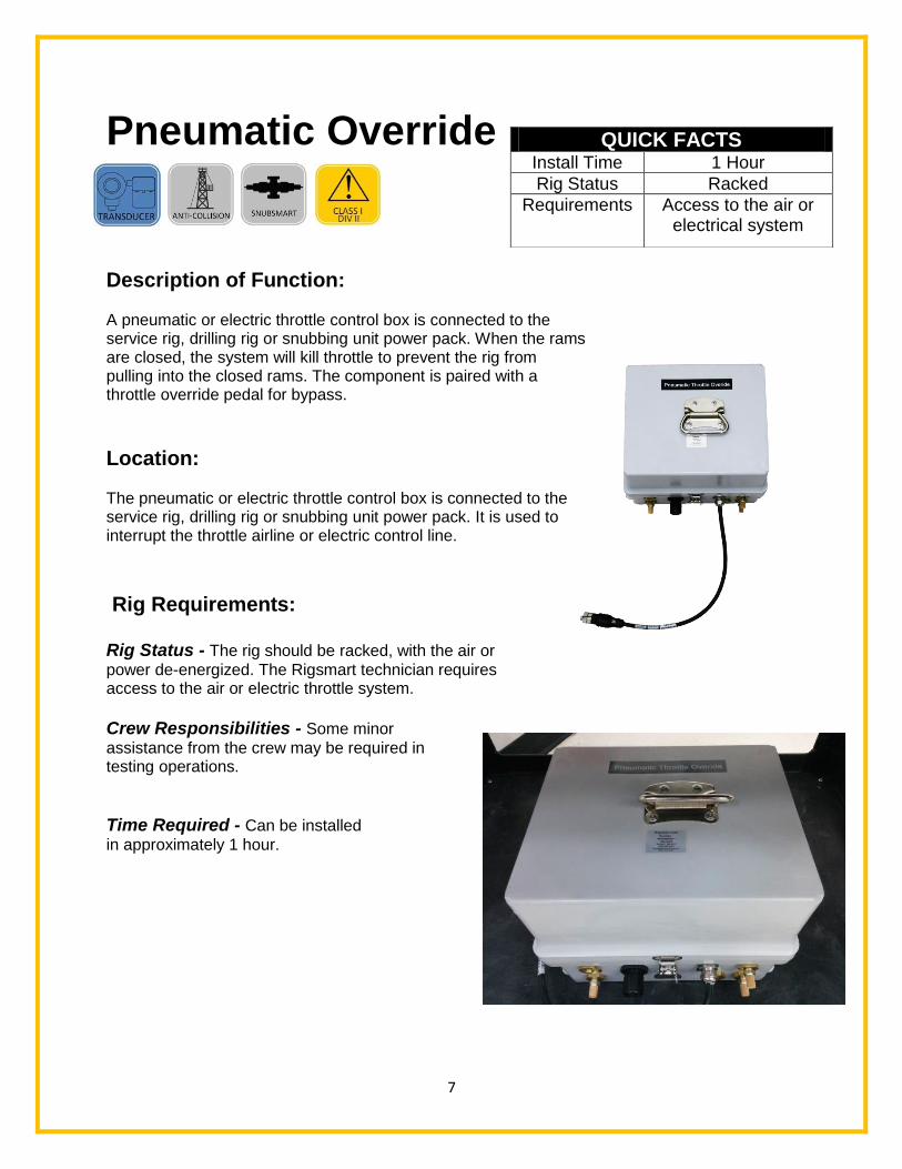
Pneumatic Override
Description of Function: A pneumatic or electric throttle control box is connected to the service rig, drilling rig or snubbing unit power pack. When the rams are closed, the system will kill throttle to prevent the rig from pulling into the closed rams. The component is paired with a throttle override pedal for bypass.
Location: The pneumatic or electric throttle control box is connected to the service rig, drilling rig or snubbing unit power pack. It is used to interrupt the throttle airline or electric control line.
Rig Requirements: Rig Status - The rig should be racked, with the air or
power de-energized. The Rigsmart technician requires access to the air or electric throttle system.
Crew Responsibilities - Some minor
assistance from the crew may be required in testing operations.
Time Required - Can be installed
in approximately 1 hour.
QUICK FACTS Install Time 1 Hour
Rig Status Racked
Requirements Access to the air or electrical system

8
Rigsmart Systems, Inc. 4908 97 St. Edmonton, AB T6L 4B2 Ph: 780.438.9475 Email: [email protected]
Pneumatic Override Data Sheet
Overview The Rigsmart Pneumatic override will cut the operators throttle in the event of an alarm. The override can be bypassed and throttle restored at a reduced rate if the operator actuates the wireless foot pedal. Once the alarm condition clears, the override releases control of the operators throttle. Operating time 100% (continuous duty) Voltage type 12 or 24 VDC Operating temperature -40°C to +60°C Operating Frequency Range 900-928 MHz in North America 868-870 MHz in Europe Material Hot compression molded fiberglass reinforced polyester (thermoset) Connection ¼” NPT Mounting options N/A Hazardous locations All internal components are rated for Class1 Division 2 Environmental Ingress Protection IP67 Application Snubbing Units
*Information subject to change without notice. Consult
the factory for the most current data and part numbers.*

9
Foot Pedal Transducer
Description of Function: The Wireless Foot Pedal provides a way for the operator to move the string at a reduced speed when an alarm condition is present. The device is wireless so it can be easily moved to wherever the operator is standing.
Location: Normally on the driller’s platform but the device can be placed anywhere, due to its wireless nature.
Rig Requirements: Rig Status – No special access is required.
Crew Responsibilities - Some minor assistance from the crew may be required in testing
operations.
Time Required – N/A
QUICK FACTS Install Time N/A
Rig Status N/A
Requirements N/A
10
Rigsmart Systems, Inc. 4908 97 St. Edmonton, AB T6L 4B2 Ph: 780.438.9475 Email: [email protected]
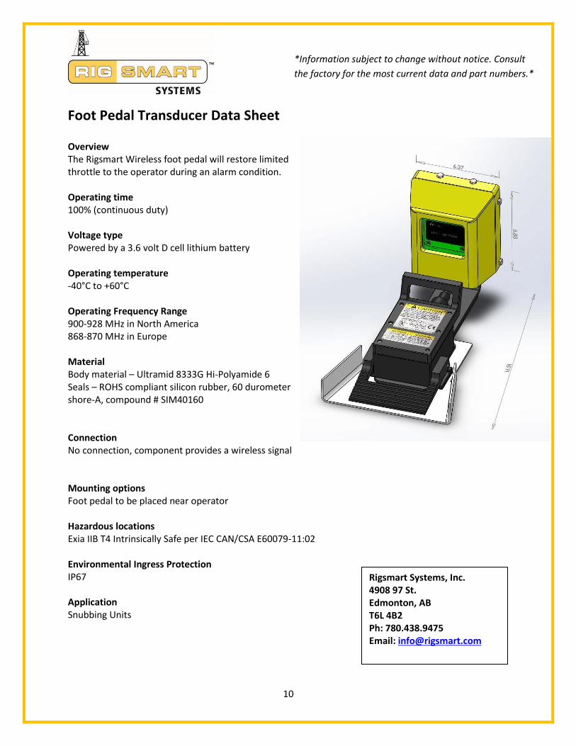
Foot Pedal Transducer Data Sheet
Overview The Rigsmart Wireless foot pedal will restore limited throttle to the operator during an alarm condition. Operating time 100% (continuous duty) Voltage type Powered by a 3.6 volt D cell lithium battery Operating temperature -40°C to +60°C Operating Frequency Range 900-928 MHz in North America 868-870 MHz in Europe Material Body material – Ultramid 8333G Hi-Polyamide 6 Seals – ROHS compliant silicon rubber, 60 durometer shore-A, compound # SIM40160 Connection No connection, component provides a wireless signal
Mounting options Foot pedal to be placed near operator Hazardous locations Exia IIB T4 Intrinsically Safe per IEC CAN/CSA E60079-11:02 Environmental Ingress Protection IP67 Application Snubbing Units
*Information subject to change without notice. Consult
the factory for the most current data and part numbers.*

11
BOP Ram Sensor
Description of Function: The BOP Ram Sensors detect whether or not the rams on the BOP stack are in the open or closed position. The sensors come in sets of two (one for each ram side) and work in conjunction. The transducer is made up of a proximity sensor that can detect when a metal object is close to it or not. The panel identifies that the ram (and which side) has been closed.
Location: The sensors are mounted on the very end of the ram. When the ram is open, the end of the ram shaft is positioned ¼” away from the sensor’s pickup.
Rig Requirements: Rig Status - The monitored equipment needs to function after
installation, for testing purposes.
Crew Responsibilities - Some minor assistance from the
crew may be required in testing operations, and creating a mount location.
Time Required - Sensors can be installed
in approximately 1 hour, once the mounts are fabricated.
QUICK FACTS Install Time 30 Minutes
Rig Status Racked
Requirements BOP access and custom bracket

12
Rigsmart Systems, Inc. 4908 97 St. Edmonton, AB T6L 4B2 Ph: 780.438.9475 Email: [email protected]
BOP Ram Senor Data Sheet
Overview The Rigsmart BOP Ram Sensor is a proximity device which detects the presence of the BOP polish rod. Operating time 100% (continuous duty) Voltage type Powered by a 3.6 volt D cell lithium battery Operating temperature -40°C to +60°C Operating Frequency Range 900-928 MHz in North America 868-870 MHz in Europe Material Body material – Ultramid 8333G Hi-Polyamide 6 Seals – ROHS compliant silicon rubber, 60 durometer shore-A, compound # SIM40160 Connection No connection, component provides a wireless signal Mounting options Brackets fabricated for various BOP’s Hazardous locations Exia IIB T4 Intrinsically Safe per IEC CAN/CSA E60079-11:02 Environmental Ingress Protection IP67 Application Snubbing units
*Information subject to change without notice. Consult the
factory for the most current data and part numbers.*
13
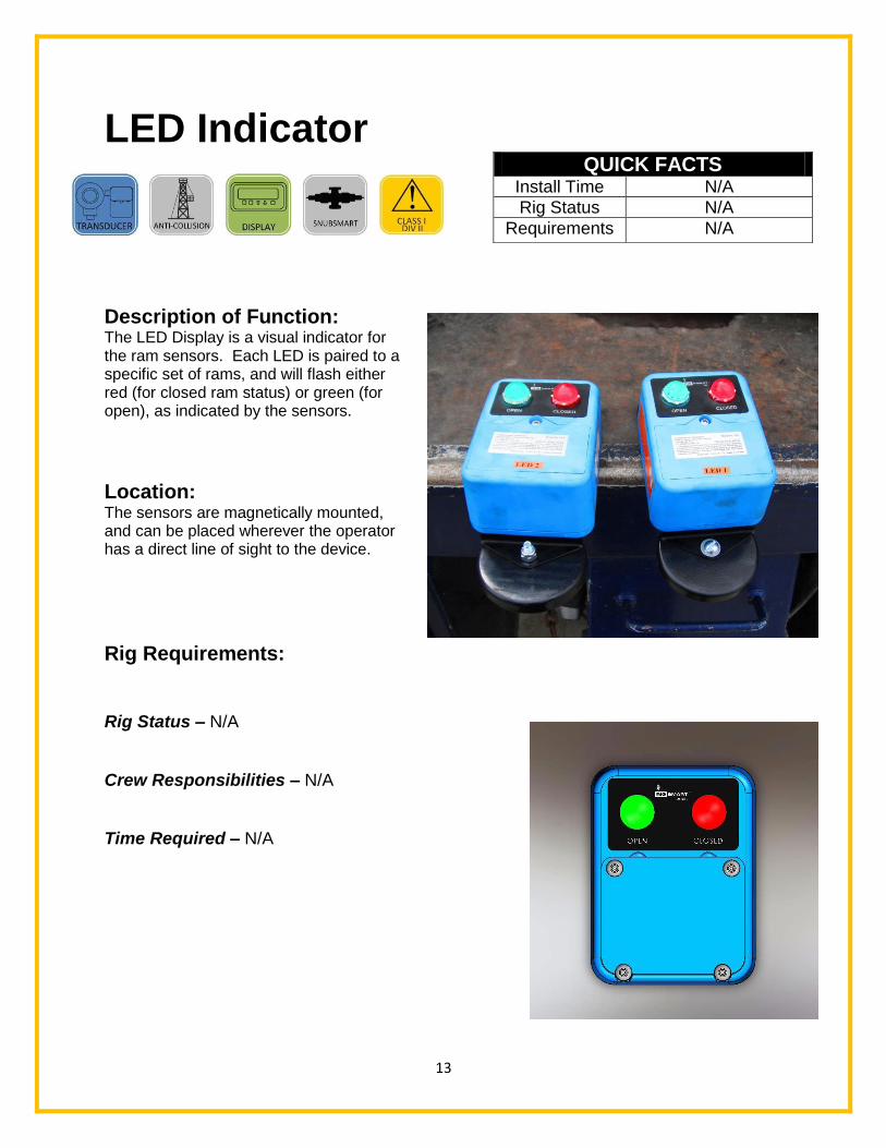
LED Indicator
Description of Function: The LED Display is a visual indicator for the ram sensors. Each LED is paired to a specific set of rams, and will flash either red (for closed ram status) or green (for open), as indicated by the sensors.
Location: The sensors are magnetically mounted, and can be placed wherever the operator has a direct line of sight to the device.
Rig Requirements: Rig Status – N/A
Crew Responsibilities – N/A
Time Required – N/A
QUICK FACTS Install Time N/A
Rig Status N/A
Requirements N/A

14
Rigsmart Systems, Inc. 4908 97 St. Edmonton, AB T6L 4B2 Ph: 780.438.9475 Email: [email protected]
LED Indicator Data Sheet
Overview The Rigsmart LED indicator visually displays the BOP status. Operating time 100% (continuous duty) Voltage type Powered by a 3.6 volt D cell lithium battery Operating temperature -40°C to +60°C Operating Frequency Range 900-928 MHz in North America 868-870 MHz in Europe Material Body material – Ultramid 8333G Hi-Polyamide 6 Seals – ROHS compliant silicon rubber, 60 durometer shore-A, compound # SIM40160 Connection No connection, component provides a wireless signal Mounting options Magnetic mounting bracket Hazardous locations Exia IIB T4 Intrinsically Safe per IEC CAN/CSA E60079-11:02 Environmental Ingress Protection IP67 Application Snubbing units
*Information subject to change without notice. Consult the
factory for the most current data and part numbers.*

15
Warning Station
Description of Function: The Warning Station receives status from the display panel on the BOP and accumulator system. Red indicates a closed ram, green indicates an open ram, and yellow indicates low accumulator pressure. The warning station also has two horns that sound different audible alarms, based on the status of the rams or accumulator.
Location: The device is mounted on top the doghouse, or other supervisor specified area.
Rig Requirements: The electric system needs to be de-energized, and access to the doghouse is required.
Rig Status – Racked
Crew Responsibilities – Assistance with
the installation location may be required.
Time Required – 1.5 – 2 hours
QUICK FACTS Install Time 1.5 – 2 hours
Rig Status Racked
Requirements Access to doghouse and de-energize electric system
16
Rigsmart Systems, Inc. 4908 97 St. Edmonton, AB T6L 4B2 Ph: 780.438.9475 Email: [email protected]
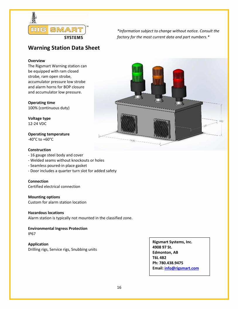
Warning Station Data Sheet
Overview The Rigsmart Warning station can be equipped with ram closed strobe, ram open strobe, accumulator pressure low strobe and alarm horns for BOP closure and accumulator low pressure. Operating time 100% (continuous duty) Voltage type 12-24 VDC Operating temperature -40°C to +60°C Construction - 16 gauge steel body and cover - Welded seams without knockouts or holes - Seamless poured-in place gasket - Door includes a quarter turn slot for added safety Connection Certified electrical connection Mounting options Custom for alarm station location Hazardous locations Alarm station is typically not mounted in the classified zone. Environmental Ingress Protection IP67 Application Drilling rigs, Service rigs, Snubbing units
*Information subject to change without notice. Consult the
factory for the most current data and part numbers.*
17
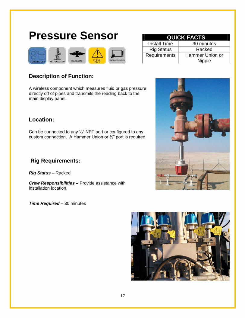
Pressure Sensor
Description of Function: A wireless component which measures fluid or gas pressure directly off of pipes and transmits the reading back to the main display panel.
Location: Can be connected to any ½” NPT port or configured to any custom connection. A Hammer Union or ½” port is required.
Rig Requirements: Rig Status – Racked Crew Responsibilities – Provide assistance with installation location. Time Required – 30 minutes
QUICK FACTS Install Time 30 minutes
Rig Status Racked
Requirements Hammer Union or Nipple
18
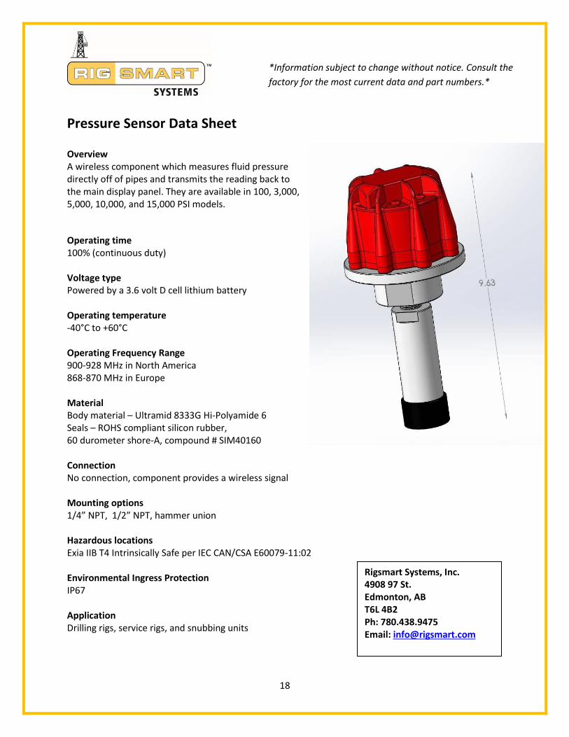
Pressure Sensor Data Sheet
Overview A wireless component which measures fluid pressure directly off of pipes and transmits the reading back to the main display panel. They are available in 100, 3,000, 5,000, 10,000, and 15,000 PSI models.
Operating time 100% (continuous duty) Voltage type Powered by a 3.6 volt D cell lithium battery Operating temperature -40°C to +60°C Operating Frequency Range 900-928 MHz in North America 868-870 MHz in Europe Material Body material – Ultramid 8333G Hi-Polyamide 6 Seals – ROHS compliant silicon rubber, 60 durometer shore-A, compound # SIM40160 Connection No connection, component provides a wireless signal Mounting options 1/4” NPT, 1/2” NPT, hammer union Hazardous locations Exia IIB T4 Intrinsically Safe per IEC CAN/CSA E60079-11:02 Environmental Ingress Protection IP67 Application Drilling rigs, service rigs, and snubbing units
*Information subject to change without notice. Consult the
factory for the most current data and part numbers.*
Rigsmart Systems, Inc. 4908 97 St. Edmonton, AB T6L 4B2 Ph: 780.438.9475 Email: [email protected]
19
Commissioning,
Testing and
Training
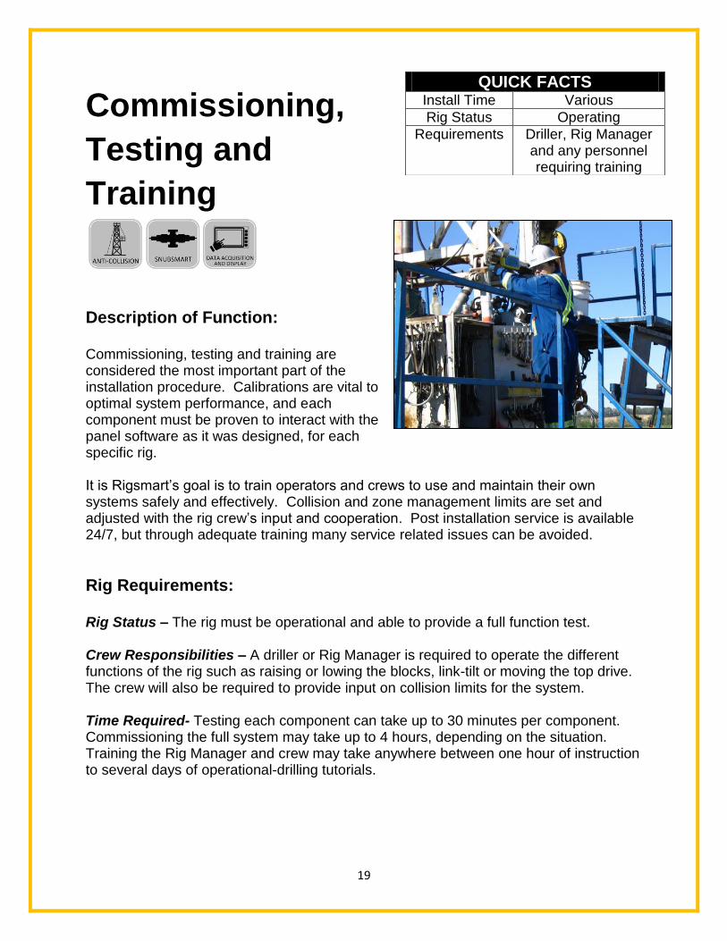
Description of Function: Commissioning, testing and training are considered the most important part of the installation procedure. Calibrations are vital to optimal system performance, and each component must be proven to interact with the panel software as it was designed, for each specific rig. It is Rigsmart’s goal is to train operators and crews to use and maintain their own systems safely and effectively. Collision and zone management limits are set and adjusted with the rig crew’s input and cooperation. Post installation service is available 24/7, but through adequate training many service related issues can be avoided.
Rig Requirements: Rig Status – The rig must be operational and able to provide a full function test. Crew Responsibilities – A driller or Rig Manager is required to operate the different functions of the rig such as raising or lowing the blocks, link-tilt or moving the top drive. The crew will also be required to provide input on collision limits for the system. Time Required- Testing each component can take up to 30 minutes per component. Commissioning the full system may take up to 4 hours, depending on the situation. Training the Rig Manager and crew may take anywhere between one hour of instruction to several days of operational-drilling tutorials.
QUICK FACTS Install Time Various
Rig Status Operating
Requirements Driller, Rig Manager and any personnel requiring training