snow roads at mcmurdo station, antarctica · snow roads at mcmurdo station, antarctica cold regions...
TRANSCRIPT
ERD
C/CR
REL
TR
-10
-5
Snow Roads at McMurdo Station, Antarctica
Col
d R
egio
ns
Res
earc
h a
nd
En
gin
eeri
ng
Lab
orat
ory
Sally A. Shoop, Gary Phetteplace, and Wendy L. Wieder May 2010
Approved for public release; distribution is unlimited.

COVER: McMurdo vehicle operation lane signage indicates where traffic is allowed.

ERDC/CRREL TR-10-5 May 2010
Snow Roads at McMurdo Station, Antarctica
Sally A. Shoop
Cold Regions Research and Engineering Laboratory U.S. Army Engineer Research and Development Center 72 Lyme Road Hanover, NH 03755-1290
Gary Phetteplace
GWA Research LLC 7 Masa Morey Lane Lyme, NH 03768
Wendy L. Wieder
Science and Technology Corporation 10 Basil Sawyer Drive Hampton, VA 23666-1395
Final report
Approved for public release; distribution is unlimited.
Prepared for National Science Foundation Office of Polar Programs 4201 Wilson Boulevard Arlington, VA 22230
ERDC/CRREL TR-10-5 ii
Abstract: Snow roads are the critical link between McMurdo Station and its snow and ice airfields. During warmer periods of the Antarctic summer, these roads can deteriorate significantly, requiring supplies and personnel to be transported by specialized limited-supply vehicles. Less severe fail-ures restrict traffic to the slow tracked-vehicle fleet. The Antarctic snow roads were observed during the 2002-2003 season to gain a better under-standing of their behavior and to identify potential performance improve-ments that could be made. Our objectives were; to explore ways to reduce the incidence of snow road failures, to understand and document current construction and maintenance procedures, and to suggest processes to optimize labor and equipment use. We monitored the snow conditions, compared strength measurements with processing techniques, monitored strength setup with time (sintering), monitored snow road temperature profiles, observed any road failures, and collected fleet data (use, vehicles, tire pressures, speeds). Our observations during the 2002 and 2003 austral summer are reported along with a substantial summary of historic snow road observations and guidance. The results of this project are timely in light of a current transportation study to consolidate to a single McMurdo airfield where the research and development to achieve a robust and resilient snow road network will be crucial for airfield operability.
DISCLAIMER: The contents of this report are not to be used for advertising, publication, or promotional purposes. Citation of trade names does not constitute an official endorsement or approval of the use of such commercial products. All product names and trademarks cited are the property of their respective owners. The findings of this report are not to be construed as an official Department of the Army position unless so designated by other authorized documents. DESTROY THIS REPORT WHEN NO LONGER NEEDED. DO NOT RETURN IT TO THE ORIGINATOR.

ERDC/CRREL TR-10-5 iii
Contents Figures and Tables .................................................................................................................................. v
Preface ................................................................................................................................................... vii
Nomenclature .........................................................................................................................................ix
Unit Conversion Factors ........................................................................................................................xi
1 Introduction ..................................................................................................................................... 1 Issue .......................................................................................................................................... 1 Objective and approach ........................................................................................................... 1
2 Background ..................................................................................................................................... 3 Literature review ....................................................................................................................... 3
Snow roads constructed over permafrost .................................................................................. 4 Snow roads constructed over permanent snow fields and ice .................................................. 5 Snow age-hardening .................................................................................................................... 7
Navy guidance ........................................................................................................................ 10 Mechanisms of snow properties related to road construction ................................................ 11 Evolution of Navy snow road technology .................................................................................. 15 NCEL recommended construction techniques ......................................................................... 15 Maintenance .............................................................................................................................. 18
Additives and other methods to improve strength ............................................................... 19 Wood chips and sawdust ........................................................................................................... 19 Ice chip cover ............................................................................................................................. 20 Ice-capped snow roads .............................................................................................................. 20 Ice aggregate roads ................................................................................................................... 20 Geocells ...................................................................................................................................... 22 Compacted snow blocks ............................................................................................................ 23 Contemporary snow milling groomer ........................................................................................ 24
Climate change ....................................................................................................................... 26
3 Snow Road Assessment Methods .............................................................................................. 28 Measurements ....................................................................................................................... 28
Strength ...................................................................................................................................... 28 Density ........................................................................................................................................ 32 Temperature profiles ................................................................................................................. 33 Snow moisture ............................................................................................................................ 33
Road use and maintenance observations ............................................................................ 33 Specific experiments .............................................................................................................. 36
Effect of speed ........................................................................................................................... 36 Rolling and tire packing ............................................................................................................. 36

ERDC/CRREL TR-10-5 iv
4 Test Sites ....................................................................................................................................... 37
5 Results ........................................................................................................................................... 41 Strength .................................................................................................................................. 41
Rammsonde Cone Penetrometer .............................................................................................. 41 Clegg Impact Hammer ............................................................................................................... 49
Density .................................................................................................................................... 50 Williams Field Road .................................................................................................................... 50 Pegasus Road ............................................................................................................................ 52
Temperature profiles .............................................................................................................. 52 Snow moisture ........................................................................................................................ 54 Specific Experiments .............................................................................................................. 55
Effect of Speed ........................................................................................................................... 55 Impacts of rolling and dragging ................................................................................................. 56
Road use and maintenance observations ............................................................................ 60
6 Field Work Summary .................................................................................................................... 63
7 Opportunities for the Future ........................................................................................................ 67
8 References .................................................................................................................................... 69
Appendix A: Navy Technology and Guidance .................................................................................... 72
Appendix B: Additional Rammsonde Strength Profiles ................................................................... 86
Appendix C: Clegg Measurements .................................................................................................... 94
Appendix D: Snow Moisture Measurements .................................................................................... 96
Appendix E: Vehicle Information and Tire Pressure Measurements ............................................. 97
Report Documentation Page

ERDC/CRREL TR-10-5 v
Figures and Tables
Figures
Figure 1. Effect of time on the strength of processed snow as a function of temperature. ............... 8 Figure 2. Effect of time on strength of processed snow as a function of snow density. ..................... 9 Figure 3. Combined effect of time and temperature on the age-hardening processes of snow. .......................................................................................................................................................... 10 Figure 4. Push type snowblower used to fill Geocell sections. ............................................................ 22 Figure 5. Road section paved with compacted snow blocks. .............................................................. 23 Figure 6. Elements of the KRC Snow Paver:. ......................................................................................... 25 Figure 7. Annual high temperature, McMurdo Station. ........................................................................ 26 Figure 8. Average annual temperature, McMurdo Station. .................................................................. 27 Figure 9. Average temperature for December and January, McMurdo Station. ................................ 27 Figure 10. Rammsonde hardness test................................................................................................... 29 Figure 11. Standard Clegg Impact Hammer test. ................................................................................. 31 Figure 12. Using the LaChepelle Sampler to measure snow compaction inruts (top), and coring (bottom) for density profile measurements. .............................................................................. 32 Figure 13. Road temperature probes. .................................................................................................... 33 Figure 14. Snow road construction and maintenance equipment. ..................................................... 34 Figure 15. Snow road compaction equipment. ..................................................................................... 35 Figure 16. McMurdo Station snow road system. .................................................................................. 38 Figure 17. Aerial photo (looking east) of Williams Field airfield, support roads and LDB launch pad. ............................................................................................................................................... 39 Figure 18. Map showing sampling locations. ........................................................................................ 40 Figure 19. Rammsonde snow strength profiles across all three lanes of Williams Field Road at MP2 and MP4. ........................................................................................................................... 42 Figure 20. Near surface Rammsonde snow strength profiles along the Black Island Lane of Williams Field Road. ............................................................................................................................ 43 Figure 21. Near surface Rammsonde hardness data for Williams Field Road showing the consistent 180 to 400 kgf strength below 5 cm (1.97 in.) and the strong layer in the Track Lane. .......................................................................................................................................................... 44 Figure 22. Rammsonde tests on a variety of snow structures. ........................................................... 46 Figure 23. Comparison between the CRREL Rammsonde and a Snow Metric Rammsonde. ............................................................................................................................................ 47 Figure 24. Comparison of Rammsonde strength values using the small cone (solid lines) and the large cone (dashed lines). ......................................................................................................... 48 Figure 25. Williams Field Road Track Lane strength, expressed as CBR, at MP4 taken over time using the CIH. ................................................................................................................................... 50 Figure 26. Snow density profiles for Williams Field and Pegasus Roads and the LDB pad. ............ 51 Figure 27. Williams Field Road and Airfield temperatures as a function of depth.. ........................... 53

ERDC/CRREL TR-10-5 vi
Figure 28. Regressions on average temperature profiles for the Black Island Lane of Williams Field Road, Williams Field Apron and undisturbed natural snow. ........................................ 53 Figure 29. Temperature profiles for MP4, Black Island Lane of Williams Field Road during the warming trend, 2002. ....................................................................................................................... 54 Figure 30. Temperatures on Williams Field Road measured over the full 1999-2000 season. ...................................................................................................................................................... 55 Figure 31. Effect of compaction roller speed on density. Data are the average and standard deviation of 6 to 8 measurements for each speed. ............................................................. 56 Figure 32. Effect of dragging on Pegasus Road rolled with pneumatic-tired load cart. .................... 57 Figure 33. Rammsonde strength profiles before (solid line) and after rolling showing increased strength below 10 cm (3.94 in.) and decreased strength above 10 cm (3.94 in.). ................................................................................................................................................... 58 Figure 34. Measuring vehicle rutting from passenger vans and pickup trucks during the austral summer warm season. ............................................................................................................... 61 Figure 35. After trafficking, the roads suffer additional damage from snow drifting into the ruts. ............................................................................................................................................................ 62 Figure A1. Cross section showing sequence of passes for elevating snow roads with a snowblower ............................................................................................................................................... 76 Figure A2. Turn around scheme for reposition snowblower and snowplane. ..................................... 78 Figure B1. Rammsonde tests on a variety of snow structures. ........................................................... 86 Figure B2. LDB launch pad Rammsonde data. ..................................................................................... 87 Figure B3. LDB launch pad Rammsonde data, shallow depths. ......................................................... 88 Figure B4. Strength profiles changes over time on Williams Field Road, MP4. ................................. 89 Figure B5. Compilation of Williams Field Road near surface strength profiles on all lanes and along the length of the road. ........................................................................................................... 90 Figure B6. Comparison of roadway and transition area strength profiles on Williams Field Road. ......................................................................................................................................................... 91 Figure B7. Study in variability in strength profiles taken in the same vicinity on the same day . ........................................................................................................................................................... 92 Figure B8. Strength profiles on Pegasus Road before and after Delta packing. ............................... 93
Tables
Table 1. Summary of CIH measurements. ............................................................................................. 49 Table 2. Pegasus Road compaction density measurements, 2 January 2003. ................................ 52 Table 3. Roller speed effect on density, Williams Field Road MP4, 3 January 2003. ....................... 56 Table C1: CIH Measurements ................................................................................................................. 94 Table D1: Snow moisture measurement on McMurdo snow roads, 2003. ....................................... 96 Table E1: Vehicle information and tire pressure measurements. ....................................................... 97

ERDC/CRREL TR-10-5 vii
Preface
This report was prepared by Dr. Sally A. Shoop, Force Projection and Sustainment Branch, Cold Regions Research and Engineering Laboratory (CRREL), U.S. Army Engineer Research and Development Center (ERDC), Hanover, NH; Dr. Gary Phetteplace, GWA Research LLC, Lyme, NH; and Dr. Wendy L. Wieder, Consultant, Science and Technology Corporation, Hampton, VA.
The authors thank George Blasidell, formerly at CRREL and now with the National Science Foundation (NSF), for his vision, guidance and support of this work. The field season would not have been possible without the assistance of the extremely competent staff at McMurdo Station, and particularly the following personnel and many, many more:
Snow road crew: Judy Goldsberry, Mark Eisinger, Jules Uberuaga, Michael “Wally” Krall, Gerald Crist (supervisor), Paul Thur, Deborah Kunze, Bob Neimer and Jeff Scanniello
Heavy mechanic: Russ Magsig Long Duration Balloon (LDB) Launch Pad: Bill Stepp, Joe Masters and
Dave Sullivan Global Information System (GIS) support: Kelly Brunt Vehicles: Kurk Salverson & Melissa Rider Computers: Robbie Lieben Heavy transverse manager: John Wright
Excellent review comments were provided by Jason Weale and Jackie Richter-Menge of CRREL. Michael Diamond of CRREL assisted in the analysis of the historic McMurdo temperature data.
Funding was provided by the NSF, Office of Polar Programs. The contents of this report are not to be used for advertising, publication, or promo-tional purposes. Citation of trade names does not constitute an official endorsement or approval of the use of such commercial products. All product names and trademarks cited are the property of their respective owners. The findings of this report are not to be construed as an official U.S. Government position unless so designated by other authorized documents.

ERDC/CRREL TR-10-5 viii
The report was prepared under the general supervision of Dr. Bradley Guay, Chief, Force Projection and Sustainment Branch; Dr. Justin B. Berman, Division Chief; Dr. Lance D. Hansen, Deputy Director; and Dr. Robert E. Davis, Director, CRREL.
COL Gary E. Johnston was Commander and Executive Director of ERDC. Dr. Jeffery P. Holland was ERDC Director.

ERDC/CRREL TR-10-5 ix
Nomenclature
C Celsius
CBR California bearing ratio
CIV Clegg Impact Value
CIH Clegg Impact Hammer
CL centerline
cm centimeters
CRREL Cold Regions Research and Engineering Laboratory
DEW Defense Early Warning
E Elastic modulus
ERDC Engineer Research and Development Center
F Fahrenheit
ft foot
g/cc grams per cubic centimeter
GIS Global Information System
in inch
KRC Keweenaw Research Center
kg kilograms
kgf kilograms force
km kilometers
kmph kilometers per hour
kPa kilopascals
LDB Long duration balloon
LGP low ground pressure

ERDC/CRREL TR-10-5 x
lbs pounds
m meters
mi miles
mm millimeters
mph miles per hour
NCEL Naval Civil Engineering Laboratory
NSF National Science Foundation
NWT Northwest Territories
psi pounds per square inch
R Rammsonde hardness number
Ram Rammsonde
RIL Rakennusinsinoorien Liitto
RPSC Raytheon Polar Services Company
Seabees Naval Construction Forces
SIPRE Snow Ice and Permafrost Research Establishment
US United States
USACE United States Army Corps of Engineers
USAP United States Antarctic Program

ERDC/CRREL TR-10-5 xi
Unit Conversion Factors
Multiply By To Obtain
degrees Fahrenheit (F-32)/1.8 degrees Celsius
feet 0.3048 meters
gallons (U.S. liquid) 3.785412 E-03 cubic meters
inches 0.0254 meters
miles (U.S. statute) 1,609.347 meters
miles per hour 0.44704 meters per second
pounds (force) per square inch 6.894757 kilopascals
pounds (mass) 0.45359237 kilograms
pounds (mass) per cubic foot 16.01846 kilograms per cubic meter
tons (2,000 pounds, mass) 907.1847 kilograms
tons (2,000 pounds, mass) per square foot 9,764.856 kilograms per square meter

ERDC/CRREL TR-10-5 1
1 Introduction
Issue
Construction and maintenance of the snow roads supporting McMurdo Station and its airfields require approximately 4000 operator and equip-ment hours between 1 September and 30 February annually. These efforts are performed in a manner that relies heavily on the expertise of the operators on site. No specific prescription for snow road construction, maintenance, or quality control is in place. Thus, the effectiveness of the current methods has not been quantified. This is borne out by the fact that in some years the snow roads fully support wheeled traffic for the entire summer season and in other years they cannot. The cost of snow road failure is significant. In the worse case nearly all transport of personnel and supplies to and from aircraft servicing McMurdo must be via a few specialized, slow vehicles.
In addition, Antarctica and Ross Island (McMurdo Station) may be experiencing higher summer temperatures due to a range of regional climatic influences (see Climate change section). Higher temperatures compound any snow road construction or maintenance challenges, and make the roads more susceptible to failure.
Objective and approach
The Cold Regions Research and Engineering Laboratory (CRREL) in Hanover, NH documented the processes currently used to prepare and maintain the McMurdo Station snow roads. We witnessed activities in the December 2002 - January 2003 time frame, and conducted extensive interviews with snow road operations personnel. Originally, CRREL planned to work with road crews to construct a section of snow road designed to progressively “fail” during the warmest part of the austral summer. Snow property measurements of the different snow road segments would provide the strength criteria required for snow roads to support various levels of ground pressure (vehicle types). However, it was not possible to execute a test program during the 2002-2003 season; and instead, researchers monitored existing snow road strength, maintenance and vehicle fleet operations. This report also contains a literature review of snow road construction methods, background on snow compaction and

ERDC/CRREL TR-10-5 2
age-hardening, and a summary of McMurdo’s historic snow road con-struction and maintenance guidelines developed by the US Navy. It concludes with our recommendations to develop a modern snow road construction and maintenance program.

ERDC/CRREL TR-10-5 3
2 Background
Literature review
Volumes of literature are available that detail the construction and use of snow roads and airfields. This section summarizes significant contribu-tions that are applicable to constructing and maintaining snow roads in Antarctica.
Snow road development has a long history in the arctic, where they are used to traverse permafrost terrain. It is difficult to construct conventional road sections over permafrost because it is sensitive to surface disruption by any type of wheeled or tracked vehicle. Arctic construction also includes snow roads underlain by permanent snow fields, typically found in Greenland rather than in Alaska or Northern Canada.
The purpose of constructing snow roads over permafrost is different than for roads constructed over permanent deep snow fields. In permafrost areas, snow roads are used during the arctic winter season to provide an improved traffic surface and protect the underlying vegetation and perma-frost. Constructing snow roads over permafrost does not, however, differ greatly from constructing them over snow fields. The exception being the subgrade surface on which the road section is placed. Sufficient snow cover and frost depth in the active layer are required to support constru-ction activities.
Snow roads are used during the summer season in the permanent snow field regions of the arctic (specifically Greenland) and in Antarctica at McMurdo Station when the unimproved snow surface has inadequate bearing strength or may be degraded by melting and become impassable. Multiyear snow in Greenland and Antarctica provide the subgrade for building snow roads, and it is usually weaker than a frozen soil subgrade.
Several studies of snow roads, and much of the practical experience with their construction, maintenance and use, are associated with other large engineering projects. Significant examples are the Trans-Alaskan pipeline and drilling operations on Alaska’s northern slope, and other industries, like logging in Canada (Drope 1977).

ERDC/CRREL TR-10-5 4
Snow roads constructed over permafrost
In 1954 the Joint Snow Compaction Program, a Canadian investigation, concluded that measurement of snow density and hardness is the most important means of evaluating the ability of snow roads to support traffic. The program also stated that the successful movement of traffic on a snow road requires a Swiss Rammsonde hardness number of greater that 350 (Joint Snow Compaction Program 1954).
The Snow Ice and Permafrost Research Establishment (SIPRE – predecessor to CRREL) looked further at the results from the Canadian investigation. SIPRE concluded that the use of heat during processing may produce free water in the snow or temporarily increase the amount of water vapor in voids. Thus, when the temperature of the snow decreased after the heat source was removed, the free water froze or the excess vapor sublimated. Each reaction produced a large number of bonds between snow particles which resulted in harder snow (SIPRE 1954). However, SIPRE’s main conclusion, from the review of the Canadian investigation, was that further tests were needed to tightly control and limit the number of study variables.
Drope (1977) documented snow road tests during the winter of 1973-1974 in Canada’s Northwest Territories (NWT). The purpose of this test was to prove that a snow road could be constructed over arctic terrain with the strength and levelness needed to support vehicle traffic expected during construction of a large diameter gas pipeline. The study investigated snow sources for construction (i.e. snow borrow from lakes, snow captured by snow fencing, and manufactured snow). They used the following construction methods:
Windrow, load and haul snow in dump trucks to the construction site. These actives impart initial consolidation on the snow;
Place the snow, spreading and compact it with a bulldozer; After sufficient snow has been hauled and placed to complete the road,
a Toray Rotary Plow Pulvimixer was pulled over the section. The Rotary Plow Pulvimixer is a piece of farm equipment with a large drum of tines that turn at about 250 rpm. The tines penetrate the snow up to 10 inches (in.) (25.4 centimeters [cm]), churning it to reduce voids be-tween snow particles, smooth surface irregularities and provide a dense snow surface. Densities of 0.5 grams per cubic centimeter (g/cc) (31 pounds per cubic ft [lb/ft3]) were obtained.
ERDC/CRREL TR-10-5 5
The NWT study presented guidance on methods to supply snow for con-struction, detailed construction and maintenance techniques, and pro-vided some initial trafficking observations. Observations applicable to the McMurdo Station projects were;
Snow density of the completed road must exceed 0.5 g/cc (31 lb/ft3). The top 10 in. (25.4 cm) of the completed road must exceed
450 Rammsonde hardness units. Snow roads must be constructed in sequential process steps. Water sources and snow borrow sites must be carefully identified prior
to construction start. Specialized equipment, which will vary from region to region, must be
chosen and placed judiciously. Regular maintenance of the snow road must be carried out. Upon completion and sintering of the snow road, increasing traffic may
actually improve the quality of the road.
Lefebvre (1979) observed a snow road constructed to support a Canadian hydroelectric project and concluded that extensive maintenance of the road surface is required during mild weather periods to keep snow roads in trafficable condition. In addition, he remarked that traffic control must be keyed to mild temperatures to prevent damage to the road. He also concluded that charts plotting degree-days versus time may help to deter-mine the end of a snow roads service life. Daily temperature variations and periods of sunshine should be taken into account if transportation must be maintained during warm periods, and additional maintenance is required and traffic should be limited during these times.
Snow roads constructed over permanent snow fields and ice
Most experience constructing snow roads over deep snow fields derives from work in Greenland and Antarctica. Installation of Defense Early Warning (DEW)-Line stations in Greenland during the 1950s led to devel-opment of construction methods for both roads and airfields on snow fields many thousands of feet thick. Deep compaction of the snow, along with leveling and grading were required to provide a competent road surface (Johnson 1979).
Russell-Head and Budd (1989) conducted field trials near Casey Station (Australia), Antarctica for the construction of a compacted-snow runway for use by wheeled C-130 aircraft. Their investigation yielded observations

ERDC/CRREL TR-10-5 6
and procedures applicable to snow road construction. They disaggregated the snow with millers and a simple twin-gang multiple-disk plow. The snow miller proved excellent for disaggregation, but had the disadvantage of removing material from its original location. The material transfer process had to be carefully controlled to maintain quality. It was difficult to track the miller passes. It was especially easy to miss areas following periods of blizzard conditions. The simple 900-1000 millimeter (mm) (35.4-39.4 in.) diameter twin-gang multiple-disk plow chopped ice lenses found in the snow, but did not produce the same quality material as the snow miller. However, they concluded that the disk plow mixed the surface material adequately, and was much quicker and easier to control than the miller. Later studies by Alger (2008) resulted in the design and development of a snow milling machine used for maintenance of seasonal snowmobile trails which may also be suitable for Antarctic snow roads (see Additives and other methods to improve strength section).
Russell-Head and Budd (1989) found that snow compaction was best achieved by pneumatic-tired rollers, and was most efficient when the snow was moist. They constructed a very large towed roller with maximum tire pressures of 1000 kPa (145 pounds per square inch [psi]) that could be dismantled and transported by C-130 aircraft.
The final process evaluated by the Australian’s included; disaggregating the top 300 mm (11.8 in.) of snow; a five stage compaction effort using pneumatic tire rollers with tire pressures of 120, 230, 430, 700, and 1000 kPa (17.4, 33.4, 62.4, 101.5 psi); leveling with a conventional road grader fit with laser survey equipment; and small-scale smoothing of the surface using a large chain (75-mm [2.95-in.] anchor chain) dragged behind two tractors traveling along the edge of the surface. Full scale plate bearing tests of the runway constructed using this process indicated the pavement would support the wheel loads of a C-130H at maximum mass. However, they recommended further study of the potential for pavement weakening by summer melting.
Finally, Russell-Head and Budd offered the following construction management suggestions for compacted-snow pavements in Antarctica:
Develop on-site methods that work for the task at hand; Disseminate construction experience; and

ERDC/CRREL TR-10-5 7
Pass on specific site experience to incoming construction personnel on-site.
Blaisdell et al. (1995) published their results on construction and oper-ations of the Pegasus blue ice runway at McMurdo Station, Antarctica. The runway consisted of approximately 20 cm (7.87 in.) of carefully compacted snow over a high bearing capacity glacial ice. The snow was rolled with progressively heavier loads and in several lifts, allowing time for sintering between lifts. Construction started in early November and tire pressures increased as the temperature increased. The most efficient time for rolling was during the warm summer period when the snow is near melting, and the best time to compact was between 1400 and 0100 hrs. Quality control and attention to construction details were shown to be particularly imp-ortant. Routine proof tests and construction monitoring were performed to insure success. Although the resulting airfield structure was much stronger than a typical snow road, the adherence to a rigorous monitoring program was deemed essential to both types of structures. Brief details of the monitoring program for the compacted snow runway at Pegasus are outlined below. Full details are included in ETL 07-12 (USAF 2007).
A rigorous test program, complete with an on-site laboratory for sampling, strength and density measurements, is necessary.
Snow temperatures are monitored daily with permanently installed thermocouples.
Density and strength (using a Russian cone penetrometer) should be taken after every compaction operation and no less than three times per month.
Five strength, and three density, measurements should be made on transects every 300 m (984 ft) along the runway.
Proof testing with a load cart is done after final strength is achieved and prior to aircraft operations.
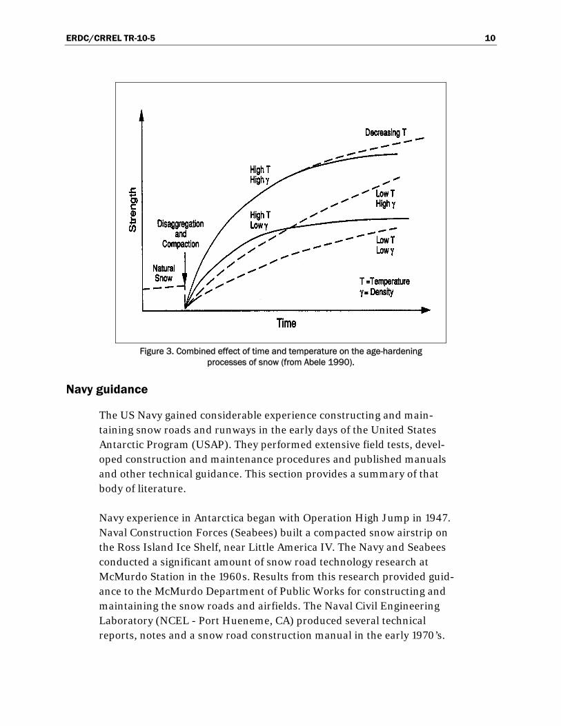
Snow age-hardening
Abele (1990) produced an excellent reference about snow material pro-perties. In it he reviewed the US Navy’s snow pavement construction tech-niques discussed below. Of particular interest are Abele’s laboratory experiments revealing the effects of time and temperature on snow strength. Abele (1990) demonstrates that snow strength generally increases as density and time increase when temperature is held con-stant or decreases. The effect of time on the increase of strength of

ERDC/CRREL TR-10-5 8
disaggregated, compacted snow is shown in Figure 1. The rate of strength gain decreases at lower temperatures (Ramsier and Sander 1965).
Figure 1. Effect of time on the strength of processed snow as a function of temperature
(from Abele 1990).
However, with early season snow road construction, age hardened snow at lower ambient temperatures ultimately gains more strength than snow age-hardened at a higher temperature. Results indicate age hardening may take an unreasonable amount of time at temperatures less than -40 °Fahrenheit (F) (-40° Celsius [C]).
The curves in Figure 1 were obtained from laboratory tests where the tem-perature was closely controlled. In the field, the age-hardening process of recently constructed snow pavements is subjected to natural temperature variations. An increase in temperature during the early stages of a snow pavement’s age-hardening process tends to increase the rate of strength gain but will decrease its ultimate strength. A temperature decrease shortly after snow pavement construction will have the opposite effect.
Changes in temperature during the later stages of the age-hardening process will primarily influence the snow pavement’s ultimate strength and have very little or no effect on the rate of any further strength

ERDC/CRREL TR-10-5 9
increase. Therefore, the relative effects of the time and temperature on the strength of a processed snow pavement suggest very clearly the most effective construction procedure (outlined below). The effect of the initial snow density (achieved during compaction) on the snow strength with time is shown in Figure 2. For the same temperature and time conditions, a higher density will result in a higher strength. The combined influence of temperature and initial density on strength increase with time is illu-strated in Figure 3. These laboratory results indicated the ideal time to construct a snow road is the summer prior to its intended use.
The construction conditions that take maximum advantage of time and temperature effects are:
A relatively high temperature (-5° to – 10 °C [23° to 14 °F] is ideal) during the snow disaggregation and compaction activities and during the early stages of the age-hardening process. This will result in a higher initial density and achieve the maximum rate of age-hardening.
A decrease in temperature when the age-hardening process is nearing completion (or has, for all practical purposes, ended) will net additional strength gains.
Figure 2. Effect of time on strength of processed snow as a function of snow density
(from Abele 1990).
ERDC/CRREL TR-10-5 10
Figure 3. Combined effect of time and temperature on the age-hardening
processes of snow (from Abele 1990).
Navy guidance
The US Navy gained considerable experience constructing and main-taining snow roads and runways in the early days of the United States Antarctic Program (USAP). They performed extensive field tests, devel-oped construction and maintenance procedures and published manuals and other technical guidance. This section provides a summary of that body of literature.
Navy experience in Antarctica began with Operation High Jump in 1947. Naval Construction Forces (Seabees) built a compacted snow airstrip on the Ross Island Ice Shelf, near Little America IV. The Navy and Seabees conducted a significant amount of snow road technology research at McMurdo Station in the 1960s. Results from this research provided guid-ance to the McMurdo Department of Public Works for constructing and maintaining the snow roads and airfields. The Naval Civil Engineering Laboratory (NCEL - Port Hueneme, CA) produced several technical reports, notes and a snow road construction manual in the early 1970’s.
ERDC/CRREL TR-10-5 11
NCEL initiated snow compaction studies to develop methods for building high-strength runways for wheeled aircraft. However, the compaction techniques they tested were not amenable to the sensitivity and non-uniformity of snow properties. They found it was not possible to construct reliable runways due to inconsistent material strength and surface hard-ness. On the other hand, the NCEL snow-compaction research resulted in the evolution of snow-road technology. During this time [1975], they found that properly constructed and routinely maintained snow roads could support passenger vehicles, pickup trucks, vans, trucks, and truck/trailer combinations fitted with floatation tires at gross weights up to 75,000 pounds (lbs) (34,019 kg) (Barthelemy 1975b).
Mechanisms of snow properties related to road construction
Barthelemy (1975b) provided a comprehensive summary of snow road technology. He discussed the mechanisms of snow properties related to the construction of snow roads. Barthelemy asserts that the two mechani-cal properties of snow most important to snow road construction are density and hardness. Density is dependent on efficiently packing snow crystals, which is the degree to which a unit volume of snow is free from void space. The hardness is dependent on the tendency of the neighboring crystals to bond to each other by ice bridges (sintering). Both density and hardness are metamorphic, meaning that they change with the passage of time and surrounding environmental conditions. Methods for snow road construction need to alter the state of natural metamorphism to accelerate the rate at which density and hardness increase.
A higher post-construction snow density provides the opportunity for many snow particles to be close to each other and thus increase sintering potential. It is common to produce initial densities of 0.5 to 0.6 g/cc (31 to 37 lb/ft3) with conventional snow road construction equipment. It is much more difficult and usually not necessary to produce initial post-construction densities above 0.6 g/cc (37 lb/ft3). During snow road con-struction, the age-hardening of snow begins immediately after processing. Hardening progresses rapidly for the first few days and then slows with time. Age-hardening is the most important process contributing to a snow road’s load-bearing capacity (Barthelemy 1975b).
As described in the Evolution of Navy snow road technology section and Appendix A, the Navy developed construction techniques to effectively accelerate natural metamorphism and increase snow density and hardness

ERDC/CRREL TR-10-5 12
through their snow road construction experiments. They investigated snow processing methods to break the particles into fine, disaggregated crystals. Compaction immediately followed processing, thereby pressing the small grains into a dense mat before intercrystalline bonding began. Thus, each grain was guaranteed a maximum number of crystal contacts and a minimum exposure to void space. Processing serves another impor-tant function because snow crystals will not automatically bond to each other simply because of their proximity; thermodynamic instability is required. Processing creates a state of physical disequilibrium that incr-eases the probability of bonding between contact surfaces and increases the potential to achieve a higher degree of hardness throughout the mass.
The most important environmental factor influencing the quality and survival of a snow road is temperature. During construction, the presence of cold temperatures within the snow mass has a marked influence on the mechanical properties. Steep temperature gradients between the air and snow surface and within the snow are conductive to rapid age-hardening. Low air temperatures are most conducive to rapid age-hardening, however there are practical limits. Studies conducted at the South Pole have shown that the rate of age-hardening is slow in the temperature range -20° to -40 °F (-29° to -40 °C), and extremely slow below -40 °F (-40 °C) (Gow and Ramsier 1964). At the opposite extreme, temperatures above 25 °F (-4 °C) severely retard age-hardening and promote sublimation.
The strength of a processed snow road changes as temperatures fluctuate. The upper layers are especially sensitive to air temperature and solar radiation. During the summer months, sustained air temperatures near the melting point may soften the surface to such an extent that the road becomes unsuitable for vehicle traffic. Also, the absorption of solar radiation decreases parabolically with depth so that the upper layers are additionally heated by the sun’s rays (NCEL 1972).
Historically a variety of different sized and shaped drags, rollers, and other devices have been used to pack snow. However, these devices are only effective to a shallow snow depth because there is a limit to the degree of density and hardness that can be achieved by compressive compaction regardless of the weight of the equipment. The enhancement of mechani-cal properties of snow is restricted to a limited depth below the surface. Compressive compaction techniques are also employed to initially compact the natural snow surface along a selected road course. This
ERDC/CRREL TR-10-5 13
precompaction procedure produces a dense smooth sub-base of uniform strength.
In the procedure of depth-processing a prescribed depth of natural snow is mechanically disturbed and then mixed. Processing damages snow’s crystalline structure, breaking it into small grains, and exposes the freshly broken surface to unstable thermodynamic conditions. Subsequent comp-ressive compaction improves the material strength, increases density through packing efficiency, increases hardness by introducing thermo-dynamic disequilibrium and maximizing crystal contact. Single-depth-processing involves processing, and if necessary reprocessing, a selected depth of snow in an area of previously undisturbed snow. The successive passes are completed before the snow has time to begin hardening (less that one hour between each pass). The construction procedures for depth-processing are discussed in more detail in the NCEL recommended construction techniques section and Appendix A.
Reprocessing of the depth-processed snow was common in the early years of snow road construction because the equipment was less refined. This technique resulted from observations made in Greenland (1954). It was noted that single-depth-processing pulverized only a limited number of particles, regardless of the number of mixer passes. Incomplete pulver-ization limited the number of particle contacts after processing. It was reasoned that reprocessing well bonded, once-processed snow should result in more thorough pulverization and smaller particle size. This rationale was substantiated by subsequent tests. Processing equipment, however, has improved over the years, and the more sophisticated equipment of present-day operations usually makes reprocessing unnec-essary. The improvement of mechanical properties realized by the added procedure and delay is marginal.
Snow roads constructed with depth-processing and compaction pro-cedures alone produce a finished pavement that is depressed below the surface of the surrounding natural snow. A depressed road traps drift snow and becomes heavily drifted-over during high-wind events. Layered-compaction construction techniques counter this problem. Borrow material removed from the surrounding natural snow is used to build the roadbed up to a desired elevation. Successive layers (also called lifts) of snow are compacted to produce the road base. Elevated road surfaces do not drift over until the bordering natural snow attains a height equal to the

ERDC/CRREL TR-10-5 14
elevated road. The drift process ordinarily takes several years. Constr-uction procedures for layered-compaction are discussed in more detail in the NCEL recommended construction techniques section and Appendix A.
In addition to minimized drifts, the layered-compaction technique provides quality control benefits and increases the load bearing potential of snow roads. The first benefit concerns hardness. Compaction produces high hardness values in the near-surface snow. Placing snow in successive lifts yields a thicker road base with more evenly distributed hardness than that obtained by compressive compaction alone. The second benefit is minimized distribution of low strength areas (also called “holidays”). Holidays are actually areas of pulverized snow that are missed or inade-quately processed. Though holidays usually occur sporadically, any single flaw may extend through the entire thickness of an unelevated road. The probability of such flaws coinciding in successive lifts a layer-compacted snow road is very low.
Early tests identified non-uniform distributions of hardness values through a depth-processed and compacted snow pavement. The vertical hardness distribution was found to be parabolic, with the bulk of the hardness in the middle two thirds of the road bed. The parabolic distrib-ution is removed with layered-compaction methods. It was noted that the surface layer of compacted snow was relatively soft and easily damaged, and a special rolling technique was required to achieve a durable road surface. A standard 13-ton (11,793-kg) pneumatic tired wobbly-wheel roller was pulled over the roadbed several times to harden the top 1 in. (2.54 cm) of the road so that the surface effectively resisted damage from wheeled vehicular traffic. A 3-day delay was required between the compl-etion of compaction and the initiation of the surface hardening proce-dures. The delay let the roadbed harden sufficiently so that the tires of the wobbly-wheel roller did not cut furrows into the compacted material.
Snow planes, commercially available land planes modified for polar use, are suitable for both grading and planning operations. These are tractor-towed with a ski suspension system for over snow operation. Snow planes effectively grade natural and compacted snow, grade drift snow, and move snow to build up or level a snowfield. Snow planes smooth and level roadbed sites prior to compaction. It is sometime necessary to first pre-pack and rough-level with a bulldozer. When used in conjunction with snow mixers, snow planes are especially critical; the roadbed must be

ERDC/CRREL TR-10-5 15
smooth and level because snow mixers tend to amplify contours or uneven surfaces. In the layered-compaction technique, it is necessary to smooth and level the surface of the road each time new snow is added.
Evolution of Navy snow road technology
The bulk of Navy snow compaction experience was derived from research conducted in the Antarctic beginning in 1960 and lasting through the 1970s. In the early 1960s roads were constructed and abandoned as tech-nologies were investigated (a more detailed description of these activities is located in Appendix A). One significant finding of this work was the importance of following specific construction procedure. A 1967 report by NCEL highlighted the importance of procedure in constructing snow pavements:
…a full-time supervisor was placed on the job to insure com-pliance with the procedures [overlapping passes of snow mixers]. Initially, the operators were not receptive to the changes, but as the work progressed, four out of five adjusted to the changes and commented on its merits over the system used previously (NCEL 1967).
Many miles of snow roads were constructed around McMurdo Station after 1969. They connected it to outlying air transport sites such as the sea-ice runway, the glacier-ice runway at Outer Williams Field, and the skiways at Williams Field. Road systems frequently changed due to failures, relocation of old roads, and construction of new roads. NCEL field teams made annual trips to the Antarctic to further develop snow road technology. Not all road construction was performed by NCEL because they were focused on snow road research. However, the NCEL roads were designed and placed to simultaneously satisfy McMurdo area trans-portation requirements. The Public Works Department at McMurdo Station used equipment and procedures developed or recommended by NCEL to construct their service roads. Barthelemy (1975b) presented a brief year-by-year review of the progress in Antarctic snow road tech-nology. A summary of his review is provided in Appendix A.
NCEL recommended construction techniques
Barthelemy (1975a) indicated that all snow roads are sensitive to quality control. In order to achieve and maintain a durable road of consistent

ERDC/CRREL TR-10-5 16
strength and quality, construction and maintenance efforts must be exe-cuted according to detailed procedures. Special attention to detail freq-uently determines the difference between a functional road and an impassable quagmire during the peak temperature summer months. Two methods of construction for elevated snow roads were developed by NCEL.
Layered-compaction
Layered-compaction is the most recent technique NCEL developed to minimize the number of operators and equipment required. It involves elevating the pavement to a desired height by compacting successive 4-in. (10-cm) layers of snow without using snowmixers. A rotary snowplow is used to gather, process, and deposit the snow material. The recommended basic equipment and construction procedures are summarized below.
Equipment:
1. Tracked personnel and cargo carrier 2. LGP D8 tractor (four required for optimum construction) 3. LGP D4 tractor with angle blade 4. Ski-mounted snowplow or snowblower 5. Snow Plane, 40- or 80-ft (12.2 – 24.4 m) model 6. Pneumatic-tired, wobbly-wheel roller 7. Eight-foot (2.4-m) diameter steel roller 8. Timber drag 9. Large rubber-tired tow vehicle
Procedure:
1. Select and stake the roadbed site. 2. Compact and level the roadbed. 3. Deposit and shape snow along side of road for containment berms. 4. Elevate to grade by compacting successive 4-in. (10-cm) layers of snow
blown onto the roadbed. 5. Level, finish, and age-harden.
It is essential to deposit, spread, and compact each 4-in. (10-cm) layer during a single work shift. A new road may be built in sections to realize this requirement. This construction method produces a finished pavement at least 30 ft (9.1 m) wide and is elevated 24 to 30 in. (61 to 76 cm) above the surrounding terrain.

ERDC/CRREL TR-10-5 17
Thomas and Vaudrey (1973) present the development of this procedure and Barthelemey details this method in his construction and maintenance guide. Some of Barthelemy’s key points are presented in Appendix A. Thomas and Vaudrey (1973) emphasized that depositing layers of only 4 in. (10 cm) or less is the single most important requirement for layered-compaction. This method reduced construction times by more than 40 % and eliminated the requirement for expensive, unique ski-mounted snow mixers, special low-geared tractors, and operators’ skill not readily available in naval construction battalions, while resulting in roads with both densities and shear strengths comparable with snowblown, pulvimixed roads.
Depth-processing
The alternative method of snow road construction proposed by the Navy is depth-processing (NCEL 1972). The same basic construction equipment is required, with the addition of two snow mixers. Although less desirable, one mixer can be used. Unlike the layered-compaction technique, the rotary snowplow is not an essential item when depth-processing snow. The snow can be pushed onto the roadbed using bulldozers. Therefore, in situations where a snowplow is not available, depth-processing is pre-ferred. However, Barthelemy (1975b) indicates that this method requires specially built, ski-mounted snow mixers, and is critically sensitive to quality control during construction. Snow road construction using depth-processing is summarized below.
Procedure:
1. Select and stake the roadbed site. 2. Deposit snow on roadbed using rotary snowplow or bulldozers. 3. Level with 40- or 80-ft (12- or 24-m) snow plane. 4. Depth-process using snow mixers. 5. Re-level, finish, roll and age-harden.
The detailed process for depth-processing is documented in Snow Road – Construction and Maintenance Manual (NCEL 1972) and summarized in Appendix A.

ERDC/CRREL TR-10-5 18
Maintenance
Properly constructed high-strength snow roads should support traffic throughout the Antarctic summer season (NCEL 1972). However, the strength and durability of the road depends on temperature; and high temperatures (relative) and solar radiation are prevalent during the mid-summer season. As the temperature of snow rises, the snow becomes weaker and softer and is easily damaged by heavy traffic of wheeled vehicles. Surface damage is greater if vehicles are operated with high tire pressures. Periodic maintenance is required to keep snow roads in usable conditions. The high maintenance months for snow roads in Antarctica are December and January. Proper timing is essential and daily surface maintenance is required during these months.
Ordinarily, conscientious, routine maintenance is sufficient to maintain snow roads. However, timing and prevention are vital for effective maint-enance. If proper procedures are not followed in time, major road repairs will probably become necessary. Techniques developed by the Navy apply to snow roads constructed by both the layered-compaction and the depth-processing methods.
Routine maintenance
The three major routine maintenance problems or distresses on high-strength snow roads are drifting, rutting, and formation of potholes. Routine maintenance practices are not complicated, usually involving removal of excess snow, dragging, grading or filling of potholes with ice chips and water, but again they must be performed in a timely manner to prevent further degradation of the snow road surface. Typical road dist-resses and routine maintenance practices are described in more detail in Appendix A.
Major road repairs
On occasion, a snow road may deteriorate so badly in certain areas that filling with ice chips, grading, or any other routine maintenance procedure is not sufficient to repair the damage. More drastic measures are nec-essary. If the deteriorated section is large, the snow blower should be used. The procedure is the same as that used in the road’s construction and is described in more detail in Appendix A.

ERDC/CRREL TR-10-5 19
Additives and other methods to improve strength
Others have investigated different methods of improving snow to bring additional strength and longevity to snow roads. These typically involve mixing other materials with the snow in an attempt to improve strength characteristics, but other techniques are discussed.
Wood chips and sawdust
Use of wood sawdust or small wood chips was investigated in the later half of the 1980s by Lee et al. (1989) and Barber and Brown (1993). Testing with samples prepared in the laboratory and test sections in the Antarctic gave promising results for snow/wood mixtures of 5 % to 10 % volume wood.
Test sections of wood/snow mixes at both McMurdo and South Pole Stations resulted in increased strength over roads constructed of pro-cessed snow only. The strengthening effect was greater at McMurdo Station than at South Pole (Lee et al. 1989). This indicated that sawdust was a more effective binder material at higher ambient and snow temp-eratures because direct solar radiation brought the snow/wood mixture to, or closer to, the melting point.
These tests resulted in roads with higher strengths at depth. However, it should be noted that reduced strengths in the top 25 cm (9.8 in.) were observed on all test plots at the South Pole and McMurdo, and were likely due to solar radiation. The effect was augmented by the substantially higher ambient air temperatures at McMurdo which brought [too much of] the upper sections to their melting point. This resulted in deeper ruts in the wood/snow sections. The snow/sawdust section continued to exhibit substantially higher strengths below this 25-cm (9.8-in.) layer.
Also, the adsorption of solar radiation by the sawdust-treated test section at McMurdo resulted in the sublimation of the snow at the surface, thus tending to concentrate the sawdust. This effect was not uniform in its intensity, and as a consequence surface ablation resulted in a rougher riding road than expected. It should be understood, however, that the remaining sawdust-treated snow had more than sufficient strength and held up to traffic. It may require additional maintenance to restore surface smoothness during warm periods (Lee et al. 1989).

ERDC/CRREL TR-10-5 20
Ice chip cover
Moser (1971) commented that from 1957 a 4- to 6-in. (10.2- to 15.2-cm) thick cover of finely chipped-ice produced with a paddle-type pulvimixer was used to protect the surface of the annual sea-ice runway on McMurdo Sound from solar radiation and near-thaw temperatures during the summer season. He reported that the chipped-ice cover provided ample runway protection and improved traction on the ice surface. Moser also commented on the use of ice chips on snow road surfaces for the same reasons.
Ice-capped snow roads
In a 1973 study reported by Adam and Hernandez (1977) a snow road con-structed without the use of heavy drags and rollers failed, but was brought back to service condition by sprinkling approximately 20 liters of water per square meter (0.49 gallons per square ft.) from a water truck. The ice-capping of the road increased its density from 0.50 to 0.63 g/cc (31.2 to 39.3 lb/ft3), and its average Rammsonde hardness from 75 to 646, 12 hours after the ice cap was applied. The density of the ice cap itself was 0.85 g/cc (53.1 lb/ft3).
The ice-capped road was used to complete the testing program with only the following comment; that by late March (testing occurred in the NWT, Canada), temperatures were high enough for the surface to melt and puddles to form. The moisture caused two curves of the test section to become extremely icy and treacherous.
Johnson (1979) reports Husky Oil’s construction of a 35-mile (56.3 km) snow road to Colville River in Northwestern Alaska in early 1978 using one million gallons (3,785 m3) of water per mile during construction and another half million gallons (1,893 m3) during hauling operations. Using an average width the 35 ft (10.7 m); Husky used 10 in. (25.4 cm) of water during construction and an additional 5 in. (12.7 cm) of water for maintenance.
Ice aggregate roads
Johnson (1979) briefly mentions two cases of ice aggregate roads and reports that they probably withstand some thawing better than snow roads.

ERDC/CRREL TR-10-5 21
Johnson reports that a technology breakthrough was achieved by E. N. Fisher with his development of the ice aggregate concept. Funded by the Alaskan Arctic Gas Study Company, Fisher carried out a field test of the ice aggregate road concept in Fairbanks, Alaska in early 1977. Six test sections were constructed and evaluated through breakup. As developed by Fisher, ice aggregate is ice which has been obtained from a frozen lake, pond or river and placed to build a road. The ice can be obtained by ripping with a tractor but the pieces tend to be large and must be crushed in some manner to obtain the size gradation desired. Another technique Fisher used was a conventional agricultural rototiller to chip the ice from the surface. The ice aggregate, consisting of a range of sizes, was then loaded with a front end loader, trucked to the site, end-dumped, packed and finally watered to develop a wear surface.
Husky Oil also used ice aggregate roads at Tunalik in Northwestern Alaska during the winter of 1977-78 with good performance (Johnson 1979) Both of these ice aggregate roads used water to establish a wear surface. Fisher did not measure the quantity of water used during construction, but he noted that water was applied until the surface appeared saturated. The ice aggregate used by Fisher contained substantial quantities of “fines” which would tend to hold water. Construction took place around 0 °F (-18 °C). Husky applied substantial quantities of water in repeated applications. Their aggregate was coarser than that used by Fisher, and would have been less apt to saturate as drainage could occur more easily. Total quantities of water applied by Husky are unknown, but Johnson (1979) hypothesized that they were undoubtedly substantially greater that those used by Fisher.
Johnson visited the ice aggregate test section at Fairbanks in late April 1977. He reported that perhaps 15 in. (38 cm) of the ice aggregate road seemingly remained intact and useable, although it was surrounded by melt-water ponds several inches deep. A snow road in the same area had completely melted. Johnson suggests ice aggregate’s resistance to melting compared to the snow road is likely due to the following factors:
Greatly reduced surface area for melting. Packed snow retains a very large number of small crystals and a tremendous surface area while the larger ice aggregate particles have surface areas perhaps two or three orders of magnitude less.
Better bonding between pieces of ice aggregate than that between snow particles. Packed snow normally turns to slush when it is wetted in the

ERDC/CRREL TR-10-5 22
spring and the bonds fail. Ice aggregate has fewer but much larger and less fragile bonds than snow.
Geocells
Diemand et al. (1996) explored two snow road construction methods that demonstrated considerable promise in the initial road preparation, and for subsequent repair or reinforcement of an existing road; Geocells and com-pacted snow blocks.
Geocells are used with great success in sandy soil conditions. Geocells are used by the military in sandy regions. When filled with sand or gravel, the material produces a hard and durable surface that can be used by wheeled vehicles of all types. It is available in a number of different sizes, and in two colors; black or white. An advantage of using Geocells with snow is that they can be laid down and filled relatively quickly, Figure 4. Once filling is complete, the area can be used immediately for less demanding applications. The bearing strength increases as the material sinters.
Figure 4. Push type snowblower used to fill Geocell sections (from Diemand et al. 1996).
Diemand et al. (1996) tested the use of Geocells with snow during December 1991 in Houghton, Michigan. The Geocell used was an expan-dable plastic web designed for soil confinement and stabilization. The

ERDC/CRREL TR-10-5 23
expanded cells were about 20 cm (8 in.) in diameter. The cells were filled by blowing snow from a surrounding field and depositing the disaggr-egated snow onto the honeycomb sections (Figure 4). Compaction of the snow into the cells was accomplished with repeated passes of a 3/4-ton (630-kg) nominal payload pickup truck. The final product was suitable for use by heavy equipment after a very short time.
Compacted snow blocks
Diemand et al. (1996) also studied the use of compacted snow blocks for improving snow roads, Figure 5. Porous snow permits vapor movement and infiltration of fluids that cause strength loss through recrystallization or partial melting. This study aimed to reduce the circulation of air and fluids by compacting the snow to densities greater than 0.82 g/cc (51 lb/ft3). A hot pressing technique compacted snow into bricks of white-ice with densities of 0.8 to 0.9 g/cc (50 to 60 lb/ft3).
Figure 5. Road section paved with compacted snow blocks (from Diemand et al. 1996).
Hot pressing, in which particles of a parent material near its melting point are compacted at high pressures, is often used in metal and ceramic manu-facturing. It reduces defect size and grain growth over the standard method of forming the material under pressure followed by heating to complete the sintering. In hot pressing, the end product has effectively

ERDC/CRREL TR-10-5 24
completed the sintering process (reached its maximum strength) before it leaves the mold. By compacting snow at very high pressures to a density greater that 0.80 g/cc (50 lb/ft3) Diemand et al. (1996) produced strong, impermeable ice blocks suitable for use as paving blocks.
The technique was field tested in Houghton, MI also during December of 1991 and documented in Diemand et al. (1996). The resulting road, cons-truction of which is shown in Figure 5, performed well when subjected to repeated trafficking (30 passes of a light truck). Diemand and Klokov (2001) give a detailed analysis of the compaction process and its effect on the resulting compacted ice properties including crystallography, and flextural and compressive strengths.
Contemporary snow milling groomer
Recent advancements to snow milling equipment used for snow machine trail maintenance have been made by Alger (2008). The design is based on studies by CRREL (Abele and Wuori 1962, and Abele 1963) in the 1960s and 1970s. Those studies indicate that mechanically milled snow, having grain sizes of one to several millimeters in diameter, compacted to a density of 0.55 g/cc (34 lb/ft3), hardens to approximately one-half its ultimate strength, or roughly 6,900 kPa (100 psi) (unconfined strength) in two to three days. More recent research at Michigan Technological University’s Keweenaw Research Center (KRC) indicated that a mixture of very finely milled snow, 1 mm or less in size, compacted to a density of 0.55 g/cc (34 lb/ft3) or higher, hardens very rapidly (within one hour) to produce a durable pavement (Alger 1993a). This surface, if thick enough, can support heavy, wheeled aircraft as well as other vehicles.
With this in mind, the grooming equipment developed at KRC has been designed to maximize mixing of the existing snow pack by use of a miller drum (Alger 1993b). A snow milling groomer was designed to accomplish smoothing, grading, milling and compaction with one piece of equipment (Figure 6). The snow milling groomer first smoothes the snow surface with a drag, which is followed by a transverse mounted miller to cut and crush the snow crystals. After the smoothing, mixing, and cutting process is completed, the snow is passed under the vibrating compactor.

ERDC/CRREL TR-10-5 25
Figure 6. Elements of the KRC Snow Paver: Overview (top), Miller (bottom left), and variable
vibration compactor plate (bottom right).
The vibration frequency of the compactor can be tuned to optimize the snow compaction based on temperature. High frequencies work best at temperatures less than -10 ºC (14 °F) (Wouri 1965). Tests using this machine on fresh snow and snowmobile trails in Houghton, Michigan, resulted in snow with compressive strengths ranging from 3,400 to 6,900 kPa (50 to 100 psi) immediately after passage through fresh snow, and over 13,800 kPa (200 psi) on trails.

ERDC/CRREL TR-10-5 26
Climate change
Climate has a strong impact on snow road construction and maintenance since the snow is already near its melting point during some of the season. Climate change may exacerbate maintenance issues for snow roads during warm temperatures. Figure 7 shows the annual high temperature at McMurdo Station for the last 20 years (calculated using data from NOAA Weather and Climate data). Figure 8 shows the average annual temper-ature and Figure 9 shows the average monthly temperatures for December and January, the two months with the highest temperatures, for the last 20 years. All three graphs show a slight increasing temperature trend. Anomalous years, such as 1988, where there was a spike in both the annual high temperature and the average December and January temper-atures, would be especially difficult for maintaining snow roads.
Jones and Reid (2001) found an increase in the annual Antarctic surface temperatures of 1.53 °C (2.75 °F) per century at stations other than McMurdo. The largest increase was apparent in the winter months, as was found for northern hemisphere polar regions by Weller (1998). This com-pared favorable to the Jacka and Budd (1998) finding of an Antarctic-wide warming of 1.2 °C (2.16 °F) per century. A decrease in Antarctic surface temperatures was found for some months (April and May).
20
25
30
35
40
45
1975 1980 1985 1990 1995 2000 2005 2010
Time (Year)
Tem
per
atu
re (
de
gre
es F
)
-6
-4
-2
0
2
4
6T
emp
era
ture
(d
eg
rees
C)
Figure 7. Annual high temperature, McMurdo Station.

ERDC/CRREL TR-10-5 27
0
2
4
6
8
10
12
1975 1980 1985 1990 1995 2000 2005 2010
Time (Year)
Tem
per
atu
re (
de
gre
es F
)
-18
-17
-16
-15
-14
-13
-12
-11
Tem
pe
ratu
re (
de
gre
es C
)
Figure 8. Average annual temperature, McMurdo Station.
20
22
24
26
28
30
32
34
36
38
40
1975 1980 1985 1990 1995 2000 2005 2010
Time (Year)
Tem
per
atu
re (
deg
rees
F)
-6
-4
-2
0
2
4
Tem
per
atu
re (
deg
rees
C)
Average January Temperature
Average December Temperature
Figure 9. Average temperature for December and January, McMurdo Station.
Antarctic surface temperature trends were seen to rise quite steadily up until 1991. In that year Mount Pinatubo (Philippines) and Mount Hudson (Chile) erupted, and it has been suggested (Jacka and Budd 1998) that these eruptions have had a major influence on the general lowering of temperatures after that year.

ERDC/CRREL TR-10-5 28
3 Snow Road Assessment Methods
A snow road field assessment program was performed during the austral summer of 2002 and 2003. It was initiated to re-assess and improve snow road technology and performance due to the huge changes in vehicle fleet and transportation since the US Navy phased out of McMurdo in the 1970’s. Snow road construction, maintenance, use and performance were observed and are documented in this section of the report. Measurements included snow road strength, density, and temperatures. Those data were compared to other constructed snow surfaces on the Ross Ice Shelf. Vehicle types used for construction and maintenance were observed, and snow road usage and standard operations were documented through casual observation and staff interviews. Lastly, we initiated preliminary experiments to determine the effects of rolling, packing and speed.
Measurements
Strength
Four instruments were chosen to measure the strength of the snow roads. The Rammsonde Cone Penetrometer, with two different cone sizes, was used to measure a strength profile with depth as the penetrometer is pounded into the snow. We attempted to use a Russian Cone Penetro-meter in some locations. However, since it is designed for stronger sur-faces, it was of limited use for the snow roads, and its results are not included in this report. The Russian Cone Penetrometer’s use is fully docu-mented by Blaisdell et al. (1995). The last technique discussed is use of a Clegg Impact Hammer to measure the integrated strength of the road surface (but not strength with depth). The Rammsonde and the Clegg, used in concert, present a complete measurement of snow road strength, and both have seen limited use on the McMurdo snow roads in the past. These two instruments compliment each other nicely as the Rammsonde takes a profile measurement while the Clegg produces a surface strength measurement with limited applicability to the strength of the structure at depth.
Rammsonde Cone Penetrometer
The Rammsonde, or Ram, was adapted by the U.S. Army and others from an instrument originally used in the Swiss Alps. It has found extensive

ERDC/CRREL TR-10-5 29
application for estimating avalanche danger and for determining allowable wheel loads on artificially compacted snow pavements. The device is a cone penetrometer consisting of a hollow, 2-cm (0.79- in.) diameter alum-inum shaft with a 60° conical tip, a guide rod, and a drop hammer. The standard cone has a diameter of 4 cm (1.57 in.) and height of 3.5 cm (1.38 in.); the total length of the penetrometer cone element (to the beginning of the shaft) is 10 cm (3.94 in.). The guide rod, inserted into the top of the shaft, guides the drop hammer. The Rammsonde hardness number R is an index which indicates snow’s resistance (in kilograms force, kgf) to vertical penetration of a metal cone of given dimensions. The hardness reading at any depth represents the mean hardness through that depth and the previous reading. The penetration force is obtained using a slide hammer of specific weight dropped from a measured height.
The hammer is raised by hand to a certain height which is read in centi-meters on the guide rod, and then dropped freely (Figure 10). The depth of penetration is read from the centimeter scale on the shaft. The resistance to penetration (hardness) of the snow can be determined by observing either the amount of penetration after each hammer drop or the number of hammer drops (blows) necessary to obtain a certain penetration. In relatively hard, homogenous snow it is usually more convenient to deter-mine the number of blows needed to penetrate through some
Figure 10. Rammsonde hardness test.

ERDC/CRREL TR-10-5 30
predetermined depth increment. Recording the number of hammer blows after each 5-cm (1.97-in.) depth increment is convenient and commonly used. In layered and new, soft snow the more satisfactory procedure is to observe the amount of penetration after each hammer blow.
The standard Rammsonde kit contains two drop hammers, 1 kg and 2 kg (0.45 lb and 0.91 lb) in weight. A combination of one of the hammer weights and a drop height ranging from 0 to 50 cm (0 to 19.7 in.) usually allows a suitable rate of penetration. Rates between 1 cm (0.39 in.) per 5 hammer blows and 5 cm (1.97 in.) per 1 hammer blow achieve good results in a wide variety of snow conditions.
The Ram hardness is computed from the following equation:
R = Whn/x + W + Q (1)
where:
R = Ram hardness number (kgf) W = weight of drop hammer (kg) h = height of drop (cm) n = number of hammer blows x = penetration after n blows (cm) Q = weight of penetrometer (kg).
The true Ram hardness of the 10-cm (3.94 in.) surface layer must be derived from a series of multipliers because of the effect the conical shape of the penetrometer head has in the vicinity of a free surface. The calcu-lation involves multiplying the hardness number obtained from the above equation; by 4.7 for the 0- to 5-cm (0- to 1.97-in.) depth, by 1.6, for the 5- to 10-cm (1.97- to 3.94-in.) depth and by 3 for the 1- to 10-cm (0.39- to 3.94-in.) depth.
In some cases, a smaller Rammsonde cone is used. The small cone has a 30° tip while the larger cone is more blunt, with a 60° tip. The correction for the small cone is
Rsmall cone = R*1.56 (2)

ERDC/CRREL TR-10-5 31
Clegg Impact Hammer
Snow road surface strength was measured using the Clegg Impact Hammer (CIH) as shown in Figure 11. The Clegg test consists of a cylin-drical mass hammer that is dropped within a guide tube from a set height. The standard Clegg uses a 4.5-kg (9.9-lb) hammer mass. The hammer is equipped with an accelerometer which measures the peak deceleration on impact. The hammer is dropped several times at each location and the readings for each drop are recorded as Clegg Impact Value (CIV). Although the 4th drop CIV reading is often used for soils strength calculations, we used an average of the 3rd, 4th and 5th drop values for the snow strength calculations.
Figure 11. Standard Clegg Impact Hammer test.
The CIV values can be converted to other strength measures such as California Bearing Ratio (CBR, %), and Ram hardness R (kgf), and Elastic modulus E (MPa) values using the equations below:
( ).CBR CIV= + 20 24 1 (3)
.
.CBR
R= 0 48
1 44 (4)
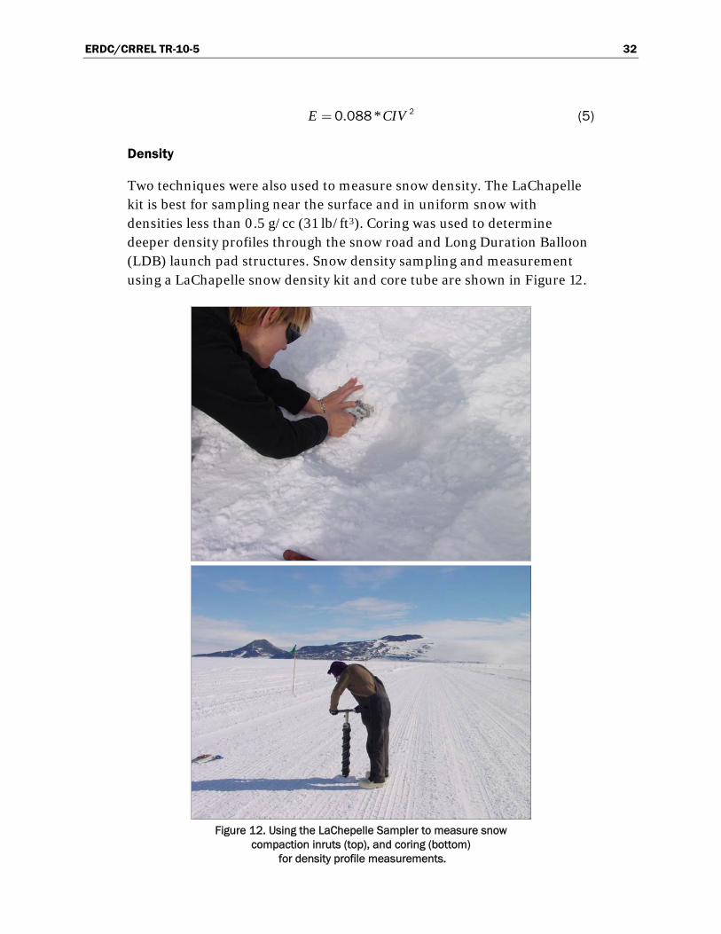
ERDC/CRREL TR-10-5 32
. *E CIV= 20 088 (5)
Density
Two techniques were also used to measure snow density. The LaChapelle kit is best for sampling near the surface and in uniform snow with densities less than 0.5 g/cc (31 lb/ft3). Coring was used to determine deeper density profiles through the snow road and Long Duration Balloon (LDB) launch pad structures. Snow density sampling and measurement using a LaChapelle snow density kit and core tube are shown in Figure 12.
Figure 12. Using the LaChepelle Sampler to measure snow
compaction inruts (top), and coring (bottom) for density profile measurements.

ERDC/CRREL TR-10-5 33
Temperature profiles
Temperature profiles were monitored using a series of thermocouple probes at various depths to approximately 90 cm (35.4 in.) as shown in Figure 13.
Figure 13. Road temperature probes.
Snow moisture
Snow moisture was measured using by a Denoth electronic dielectric snow moisture meter (capacitance meter).
Road use and maintenance observations
Snow road use and maintenance procedures were observed from 18 December 2002 to 10 January 2003. Discussions and interviews with the road maintenance crew, the motor pool, vehicle dispatch and the crew supervisors were also used to help understand the procedures related to snow road construction and maintenance. The equipment used to construct and maintain the snow roads is shown in Figures 14 and 15.

ERDC/CRREL TR-10-5 34
a. Caterpillar Challenger 95 b. Caterpillar LGP “stretch” D8
c. Goose d. Drag
Figure 14. Snow road construction and maintenance equipment.
They include:
The Caterpillar Challenger 95 (Figure 14a) is a dual-rubber-tracked agricultural tractor modified to operate in harsh Antarctic weather conditions. These tractors are designed to pull agricultural and cons-truction equipment, trailers and sleds. Prior to introduction of more modern, heavy, off-road tractors these were the backbone of the McMurdo heavy-construction fleet.
The Caterpillar low ground pressure (LGP) “stretch” D8 bulldozer (Figure 14b) was originally designed and used as a traverse vehicle in Greenland. It was specially built during the late 1950’s, and is a longer, lower ground pressure version of the standard D8. The blades are modified for use in deep snow. These stretch D8 tractors were used to haul equipment, personnel and supplies to the Camp Century construc-tion site approximately 120-mi (193-km) east of Thule, Greenland.
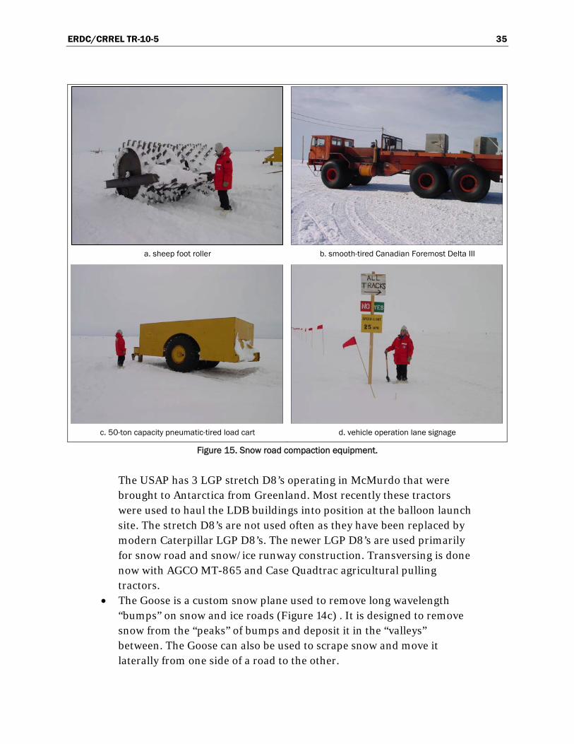
ERDC/CRREL TR-10-5 35
a. sheep foot roller b. smooth-tired Canadian Foremost Delta III
c. 50-ton capacity pneumatic-tired load cart d. vehicle operation lane signage
Figure 15. Snow road compaction equipment.
The USAP has 3 LGP stretch D8’s operating in McMurdo that were brought to Antarctica from Greenland. Most recently these tractors were used to haul the LDB buildings into position at the balloon launch site. The stretch D8’s are not used often as they have been replaced by modern Caterpillar LGP D8’s. The newer LGP D8’s are used primarily for snow road and snow/ice runway construction. Transversing is done now with AGCO MT-865 and Case Quadtrac agricultural pulling tractors.
The Goose is a custom snow plane used to remove long wavelength “bumps” on snow and ice roads (Figure 14c) . It is designed to remove snow from the “peaks” of bumps and deposit it in the “valleys” between. The Goose can also be used to scrape snow and move it laterally from one side of a road to the other.

ERDC/CRREL TR-10-5 36
A Drag is used to smooth the surface of the snow roads (Figure 14d). The drag is most commonly the last piece of construction equipment used during road construction. It is also used to redistribute snow evenly over the road surface following a snow storm or wind event.
A 50-ton (45,000-kg) pneumatic-tired load cart is used for deep roller compaction of snow lifts during layered-construction activities (Figure 15a). It is also used as a “proof” cart to test the bearing support of a road or skiway prior to opening them for heavy-vehicle and airplane traffic.
A smooth-tired Canadian Foremost Delta III is used to harden the wearing surface of snow roads (Figure 15b).
Many other pieces of equipment were seen on the runway apron and operational areas near Williams Field but we have listed only those actively involved in the road construction and maintenance operations.
The type of vehicles traveling on the roads at any specific time was loosely monitored through vehicle dispatch. When we were present, we observed Ford E350 passenger vans, Ford F350 and F250 trucks, and Canadian Foremost Deltas. A thorough assessment and documentation of the McMurdo vehicle fleet was performed by Blaisdell (1991) and again by Seman (In prep).
Specific experiments
Effect of speed
Two tests compared the density of compaction processes. A test of the effect of vehicle speed on compaction took place 3 January 2003 on the Williams Field Road. The Erebus lane was rolled with the pneumatic-tired load cart at speeds of 4, 8 and 12 miles per hour (mph) (6.4, 12.9 and 19.3 kilometers per hour [kmph]) and densities were measured under the two inside wheels of the cart.
Rolling and tire packing
The other test compared the densities created by rolling with the 50-ton (45,000-kg) capacity pneumatic-tired load cart and tire packing (with the smooth-tired Delta) on Pegasus Road (2 January 2003). Rammsonde strength profiles, Clegg Hardness, and snow moisture readings, air and snow temperature profiles were also taken at each of these test areas.
ERDC/CRREL TR-10-5 37
4 Test Sites
There are approximately 32 km (20 mi) of snow roads servicing McMurdo Station and its airfields (Figure 16). Two major roads are:
Williams Field Road, which connects Ross Island to Williams Field airfield and is constructed on deep snow.
Pegasus Road, which connects Williams Field to the Pegasus white ice airfield and is constructed on shallow-to-deep snow.
In addition, there are other operational areas such as the LDB launch pad, which is constructed on deep snow. An aerial view of the area showing the road system and the LDB pad is shown in Figure 17.
These roads and the LBD pad have been in their current configurations for over 10 years. Alignments have evolved over time due to annual recons-truction and maintenance activities. Each road is divided into lanes. Williams Field and Pegasus Roads each have three lanes; the Track Lane, Black Island Lane and Erebus Lane. At any given time, the three lanes are designated for the following uses: one lane for outbound wheeled traffic, one lane for inbound wheeled traffic, and one lane in “maintenance/ cons-truction” or “sintering” status. Tracked vehicles typically travel outside of the respective inbound or outbound wheeled vehicle lanes (see Figure 15c). The Black Island Lane is on the south side of each road, and the Erebus Lane is the northern lane, closest to Mt Erebus.
Snow strength, density, temperature and moisture measurements were taken on the Williams Field Road, Pegasus Road and the LDB pad. A few additional sites were chosen for comparison (Williams Field, virgin snow, etc.).
Williams Field Road densities were measured by coring at Mile Posts (MP) 3 and 4. A core was collected at MP4 on the Pegasus Road during our com-paction density tests completed on 3 January 2003. Reference densities in the upper layer of the virgin snow pack were obtained approximately 150 ft (46 m) south of the Pegasus Road MP4. The LDB pad was sampled on 5 January 2003, just prior to the season’s final launch on 6 January 2003. A map showing all of the measurement locations is given in Figure 18.

ERD
C/C
RR
EL TR-10-5
38
Figure 16. McMurdo Station snow road system.

ERD
C/C
RR
EL TR-10-5
39
Figure 17. Aerial photo (looking east) of Williams Field airfield, support roads (Williams Field Road far left, Pegasus Road
far right), and LDB launch pad (circle)
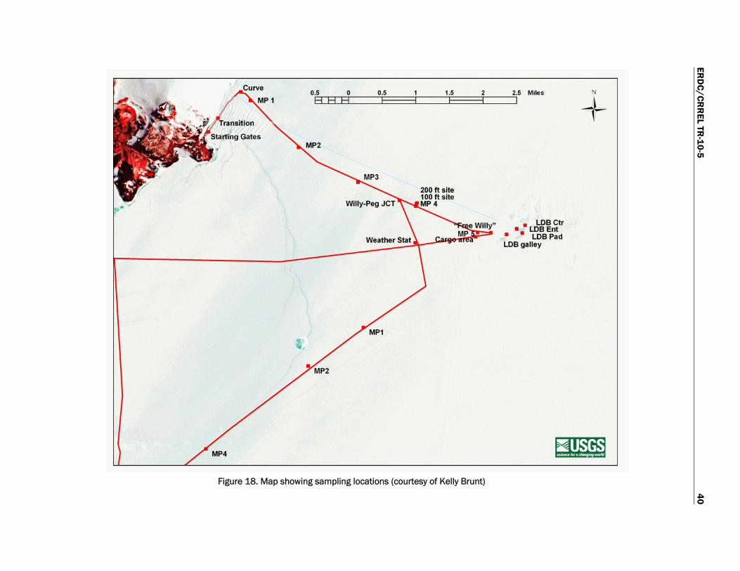
ERD
C/C
RR
EL TR-10-5
40
Figure 18. Map showing sampling locations (courtesy of Kelly Brunt)

ERDC/CRREL TR-10-5 41
5 Results
Strength
Many strength tests were conducted using the Rammsonde, the Clegg, and the Russian Cone Penetrometer. Strength measurements were taken at several locations (transition, curve, mile posts) on all three lanes of the Williams Field Road. Comparison tests were taken on the LDB launch pad and the aircraft apron at Williams Field. Differences in strength are clearly discernable and show a wide variety of strength profiles in the snow struc-tures. The Clegg Impact Hammer was used to measure the road surface layer strength to supplement the Rammsonde strength-depth profiles.
Rammsonde Cone Penetrometer
Profiles of the Rammsonde hardness data for each lane of Williams Field Road at MP2 (dashed lines) and MP4 are shown in Figure 19. Generally, the Williams Field Road surface gradually increases in strength with depth to a strong layer of between 200 to 400 Ram value (kgf), at a depth of 15 to 25 cm (6 to 10 in.). This happens closer to the surface at MP2 then at MP4. This was likely the road surface from the previous year. The Ram value was adequate for a snow road; however, strength is somewhat incon-sistent, and tended to be lower in the transition and curve areas. In addition, the loose material over this layer may be problematic. A softer layer on Williams Field Road (200 Rammsonde) existed at depths below 30 cm and it occasionally dropped to 100 Ram around 50 cm (19.7 in.). This was underlain by a very strong layer (>2,000 kgf ) at approximately 60 cm (23.6 in.), which could not be penetrated with even the small-cone Rammsonde). This may be the road surface from two years previous. This figure also clearly shows the higher strength of the Track Lane near the surface (less than 25 cm [9.8 in.]), presumably caused by the trafficking with tracked vehicles. However, notice also that the Track Lane strength decreases faster and to a lower level than the wheeled lanes between 20 and 50 cm (7.9 and 19.7 in.).
Figure 20 shows the near surface (less than 30 cm [11.8 in.]) profiles for the Black Island Lane of Williams Field Road, taken along the length of the road. Note the weak surface over a very strong layer (>1,500 kgf) at 15-cm (5.9-in.) depth near the Route 1/Williams Field Road transition at Scott

ERDC/CRREL TR-10-5 42
-80
-70
-60
-50
-40
-30
-20
-10
0
0 500 1,000 1,500 2,000 2,500 3,000
Ram Resistance (kgf)
Ave
rag
e D
epth
(cm
)
Black Island Lane MP4
Erebus Lane MP4
Track Lane MP4
Black Island Lane MP2 (dashed)
Erebus Lane MP2 (dashed)
Track Lane MP 2 (dashed)
Figure 19. Rammsonde snow strength profiles across all three lanes of Williams Field Road at
MP2 and MP4.
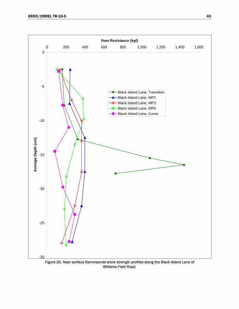
ERDC/CRREL TR-10-5 43
-30
-25
-20
-15
-10
-5
0
0 200 400 600 800 1,000 1,200 1,400 1,600
Ram Resistance (kgf)
Ave
rag
e D
epth
(cm
)
Black Island Lane, Transition
Black Island Lane, MP2
Black Island Lane, MP3
Black Island Lane, MP4
Black Island Lane, Curve
Figure 20. Near surface Rammsonde snow strength profiles along the Black Island Lane of
Williams Field Road.
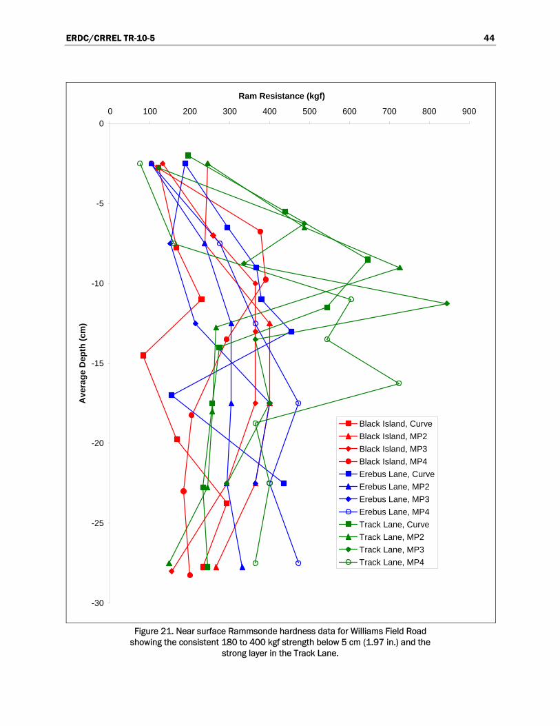
ERDC/CRREL TR-10-5 44
-30
-25
-20
-15
-10
-5
0
0 100 200 300 400 500 600 700 800 900
Ram Resistance (kgf)
Ave
rag
e D
epth
(cm
)
Black Island, Curve
Black Island, MP2
Black Island, MP3
Black Island, MP4
Erebus Lane, Curve
Erebus Lane, MP2
Erebus Lane, MP3
Erebus Lane, MP4
Track Lane, Curve
Track Lane, MP2
Track Lane, MP3
Track Lane, MP4
Figure 21. Near surface Rammsonde hardness data for Williams Field Road
showing the consistent 180 to 400 kgf strength below 5 cm (1.97 in.) and the strong layer in the Track Lane.

ERDC/CRREL TR-10-5 45
Base. This area was scraped and covered with new snow early in the season and then compacted with very heavy weight using dozers at slow speed. Also of note are the stronger near surface characteristics at MP4, and the weak layer at 15-cm (5.9-in.) depth at the curve (MP and curve locations are show in Figure 18).
Shallow depth profiles (less than 30 cm [11.8 in.]) for all lanes at several locations along the Williams Field Road are shown in Figure 21. This figure also shows some of the variability measured, and the low strength in the curve area. The increase from 180 to 400 kgf strength below 5 cm (1.97 in.) is consistent along and across the road, however. The strong layer at 7 to 17 cm (2.76 to 6.7 in.) in the Track Lane is also apparent.
We were unable to test on the Pegasus Road until construction comm-enced in early January. At that time, the Pegasus Road consisted of a strong layer (Ram 250) from 22 to 37 cm (8.7 to 14.7 in.) deep and a weak surface layer (Ram less than 100) above 12 cm (4.7 in.). These profiles are shown later in the discussion on specific tests.
A compilation of the snow strength profiles for the different snow struc-tures is given in Figure 22. The Williams Field Apron had the strongest snow layer we measured (>3,000 kgf) at approximately 35 cm (13.8 in.). It was likely the previous year’s surface. The LDB launch pad structure was weaker but more uniform with depth. The largest contrast is with the unp-rocessed snow away from the roads, which is very weak (Rammsonde hardness less than 100 kgf) until over a meter depth. Additional snow strength profiles for other engineered structures, including the LDB launch pad, are given in Appendix B.
The final aspect of the Rammsonde strength studies was a comparison between different Rammsonde tools and cone sizes. Two different Rammsonde tools were available; one was an old CRREL manufactured Rammsonde, and the other was a tool recently manufactured and purc-hased from Snow Metric. Figure 23 shows that good correlation existed between the different Rammsondes (CRREL and Snow Metric). In addition, two sizes of cones exist for a Rammsonde, with different equa-tions used to reduce the data depending on cone size. Figure 24 shows very good correlation between the data collected using the different cone sizes.
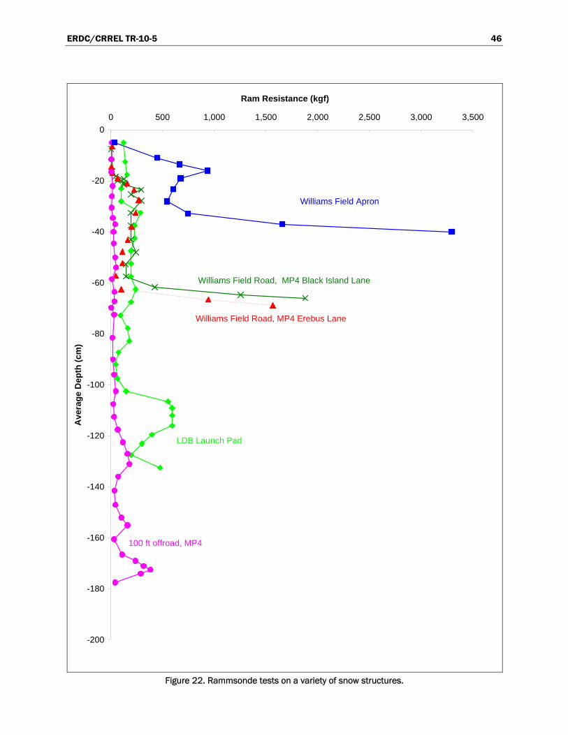
ERDC/CRREL TR-10-5 46
-200
-180
-160
-140
-120
-100
-80
-60
-40
-20
0
0 500 1,000 1,500 2,000 2,500 3,000 3,500
Ram Resistance (kgf)
Ave
rag
e D
epth
(cm
)
LDB Launch Pad
Williams Field Road, MP4 Black Island Lane
Williams Field Road, MP4 Erebus Lane
100 ft offroad, MP4
Williams Field Apron
Figure 22. Rammsonde tests on a variety of snow structures.
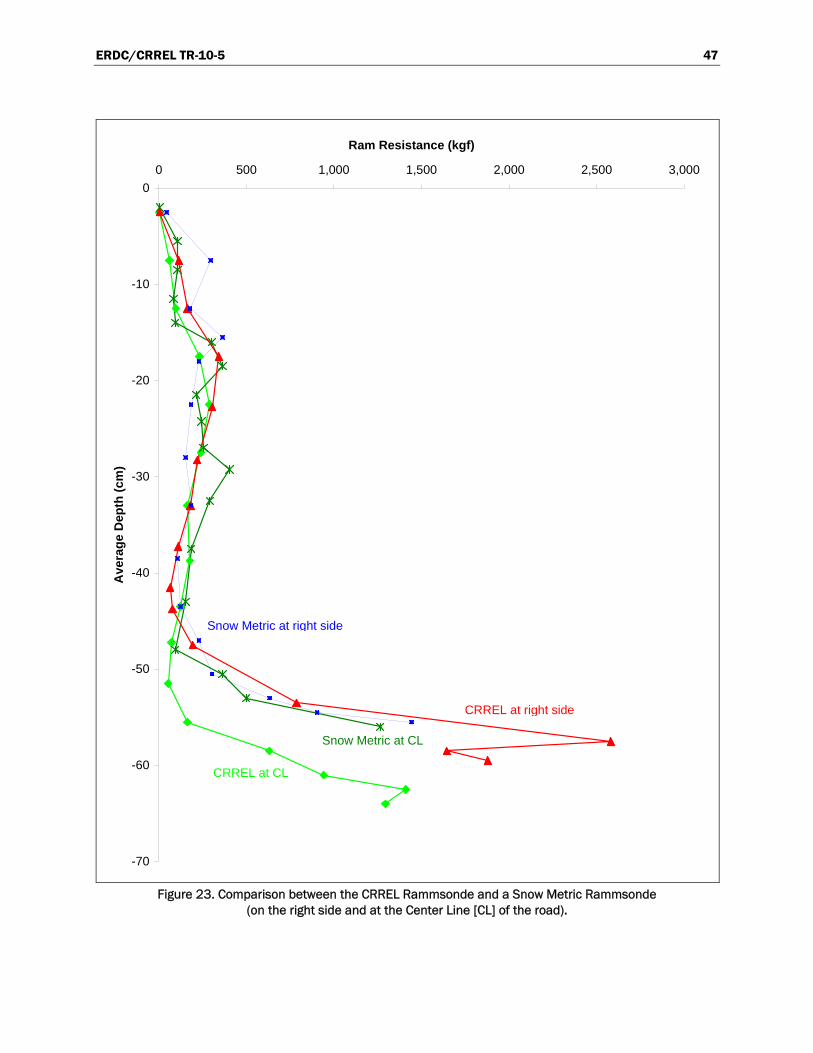
ERDC/CRREL TR-10-5 47
-70
-60
-50
-40
-30
-20
-10
0
0 500 1,000 1,500 2,000 2,500 3,000
Ram Resistance (kgf)
Ave
rag
e D
epth
(cm
)
Snow Metric at CL
CRREL at CL
CRREL at right side
Snow Metric at right side
Figure 23. Comparison between the CRREL Rammsonde and a Snow Metric Rammsonde
(on the right side and at the Center Line [CL] of the road).

ERDC/CRREL TR-10-5 48
-80
-70
-60
-50
-40
-30
-20
-10
0
0 200 400 600 800 1,000 1,200 1,400 1,600 1,800 2,000
Ram Resistance (kgf)
Av
era
ge
Dep
th (
cm)
Black Island Large Cone (dashed)
Black Island Small Cone
Erebus Small ConeErebus Large Cone (dashed)
Track Lane Small Cone
Track Lane Large Cone (dashed)
Figure 24. Comparison of Rammsonde strength values using the small cone (solid lines) and
the large cone (dashed lines).
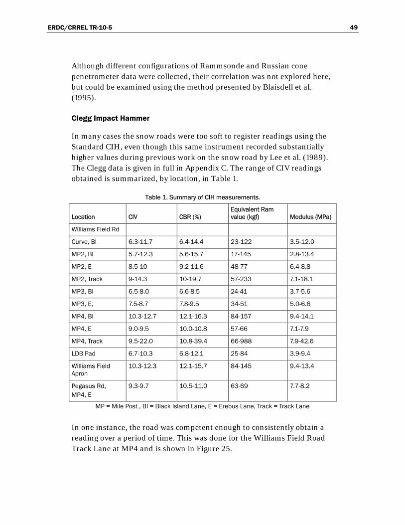
ERDC/CRREL TR-10-5 49
Although different configurations of Rammsonde and Russian cone penetrometer data were collected, their correlation was not explored here, but could be examined using the method presented by Blaisdell et al. (1995).
Clegg Impact Hammer
In many cases the snow roads were too soft to register readings using the Standard CIH, even though this same instrument recorded substantially higher values during previous work on the snow road by Lee et al. (1989). The Clegg data is given in full in Appendix C. The range of CIV readings obtained is summarized, by location, in Table 1.
Table 1. Summary of CIH measurements.
Location CIV CBR (%) Equivalent Ram value (kgf) Modulus (MPa)
Williams Field Rd
Curve, BI 6.3-11.7 6.4-14.4 23-122 3.5-12.0
MP2, BI 5.7-12.3 5.6-15.7 17-145 2.8-13.4
MP2, E 8.5-10 9.2-11.6 48-77 6.4-8.8
MP2, Track 9-14.3 10-19.7 57-233 7.1-18.1
MP3, BI 6.5-8.0 6.6-8.5 24-41 3.7-5.6
MP3, E, 7.5-8.7 7.8-9.5 34-51 5.0-6.6
MP4, BI 10.3-12.7 12.1-16.3 84-157 9.4-14.1
MP4, E 9.0-9.5 10.0-10.8 57-66 7.1-7.9
MP4, Track 9.5-22.0 10.8-39.4 66-988 7.9-42.6
LDB Pad 6.7-10.3 6.8-12.1 25-84 3.9-9.4
Williams Field Apron
10.3-12.3 12.1-15.7 84-145 9.4-13.4
Pegasus Rd, MP4, E
9.3-9.7 10.5-11.0 63-69 7.7-8.2
MP = Mile Post , BI = Black Island Lane, E = Erebus Lane, Track = Track Lane
In one instance, the road was competent enough to consistently obtain a reading over a period of time. This was done for the Williams Field Road Track Lane at MP4 and is shown in Figure 25.

ERDC/CRREL TR-10-5 50
0
5
10
15
20
25
30
35
29-Dec-02 31-Dec-02 2-Jan-03 4-Jan-03 6-Jan-03
Date
CB
R (%
) b
y C
leg
g
Figure 25. Williams Field Road Track Lane strength, expressed as CBR, at MP4
taken over time using the CIH.
The standard Clegg uses a 4.5-kg (9.9-lb) hammer mass. Subsequent to our field work, the Clegg was offered in a “light” version with a 0.5-kg (1.1-lb) mass, which was purchased for future studies. Operationally, the Clegg has the potential to build up snow inside the drop tube, which could affect the readings. It is important to keep the drop tube free of snow.
Density
Williams Field Road
The density profiles of the road structures are plotted in Figure 26. The top layer of Williams Road (0 to 15 cm [0 to 5.9 in.]) ranged in density from 0.420 to 0.560 g/cc (26.2 to 35.0 lb/ft3) and depended on the method and timing of surface processing. The data in Figure 26 show that the next layer (from 10 or 15 cm [3.9 or 5.9 in.], down to 30 cm [11.8 in.]) was both dense (densities from 0.560 to 0.700 g/cc [35.0 to 43.7 lb/ft3]) and hard (Rammsonde strength of 200 to 400). Spatially discontinuous layers existed between 30 and 55 cm (11.8 and 21.7 in.). A very competent and dense layer occurred at about 60 to 70 cm (23.6 to 21.7 in.) (Rammsonde hardness greater than 1,000 kgf and density averaged greater than 0.650 g/cc [40.6 lb/ft3]).

ERDC/CRREL TR-10-5 51
-95
-85
-75
-65
-55
-45
-35
-25
-15
-5
0.30 0.35 0.40 0.45 0.50 0.55 0.60 0.65 0.70 0.75
Density (g/cc)
Dep
th (
cm)
5 Jan 03, LDB launch pad
24 Dec 2002, MP4 Williams Field Rd
Near Surface using La Chapel
24 Dec 2002, MP4 Williams Field Rd
30 Dec 2002, MP3 Williams Field Rd
3 Jan 03, MP4 Pegusus Rd
Figure 26. Snow density profiles for Williams Field and Pegasus Roads and
the LDB pad (All samples from Black Island Lane of Williams Field Road except as noted).

ERDC/CRREL TR-10-5 52
Pegasus Road
A density profile for the Pegasus Road is also shown in Figure 26, with additional data contained in Table 2. Density in the top layer (depth less than 15 cm [5.9 in.]) ranges from 0.415 to 0.583 g/cc (25.9 to 36.4 lb/ft3). Once again, the layers below 15 cm (5.9 in.) are high in density, ranging from 0.558 to 0.654 g/cc (34.8 to 40.8 lb/ft3). Rammsonde strength tests showed the strengths in the 20-to 30-cm (7.9- to 11.9-in.) depth range to be about 150 to 350 kgf. Pegasus Road also has a strong layer at the approximately 60-cm (23.6-in.) depth.
Table 2. Pegasus Road compaction density measurements, 2 January 2003.
Density (g/cc)
Number of Samples
Standard Deviation (g/cc) Range (g/cc)
Depth Range (cm)
Mile Post 4, Erebus Lane, 11:00 AM
Before packing 0.472 4 0.0500 0.400-0.540 2-7.5
After packing with Smooth-tired Delta
0.566 6 0.0094 0.550-0.570 5-10
Mile Post 1, Black Island Lane, 3:00 PM
Unrolled, dragged in AM 0.466 3 0.0094 0.460-0.480 6-12
Immediately after rolling, in ruts 0.507 4 0.0083 0500-0.520 4-14
Immediately after rolling, between ruts
0.490 3 (0.0200) 0.460-0.500 6-14
Mile Post 4, Black Island Lane, 4:45PM
Unrolled and undragged 0.415 2 (0.015) 0.400-0.430 4-14
In cart ruts 0.510 3 0.0216 0.490-0.540 6-15
Mile Post 4, Erebus Lane, 5:00 PM
In Delta tire track 0.505 2 0.005 0.500-0.510 3-12
Temperature profiles
Figure 27 shows that the temperatures were quite consistent from one location to another. The change in temperature gradient based on snow structure profile was revealed when data were grouped by snow structure. This was most evident in density, which impacts thermal conductivity and specific heat. Figure 28 shows regressions on the temperature profiles for three different snow constructions: the Williams Field cargo apron (strongest and most dense), the Williams Field snow road, and the
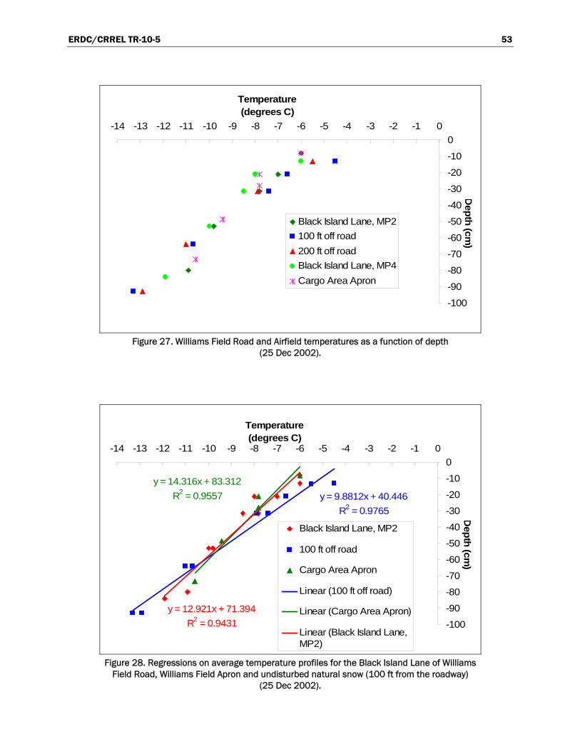
ERDC/CRREL TR-10-5 53
-100
-90
-80
-70
-60
-50
-40
-30
-20
-10
0
-14 -13 -12 -11 -10 -9 -8 -7 -6 -5 -4 -3 -2 -1 0
Dep
th (c
m)
Temperature (degrees C)
Black Island Lane, MP2
100 ft off road
200 ft off road
Black Island Lane, MP4
Cargo Area Apron
Figure 27. Williams Field Road and Airfield temperatures as a function of depth
(25 Dec 2002).
y = 9.8812x + 40.446
R2 = 0.9765
y = 14.316x + 83.312
R2 = 0.9557
y = 12.921x + 71.394
R2 = 0.9431 -100
-90
-80
-70
-60
-50
-40
-30
-20
-10
0
-14 -13 -12 -11 -10 -9 -8 -7 -6 -5 -4 -3 -2 -1 0
Dep
th (c
m)
Temperature (degrees C)
Black Island Lane, MP2
100 ft off road
Cargo Area Apron
Linear (100 ft off road)
Linear (Cargo Area Apron)
Linear (Black Island Lane,MP2)
Figure 28. Regressions on average temperature profiles for the Black Island Lane of Williams
Field Road, Williams Field Apron and undisturbed natural snow (100 ft from the roadway) (25 Dec 2002).
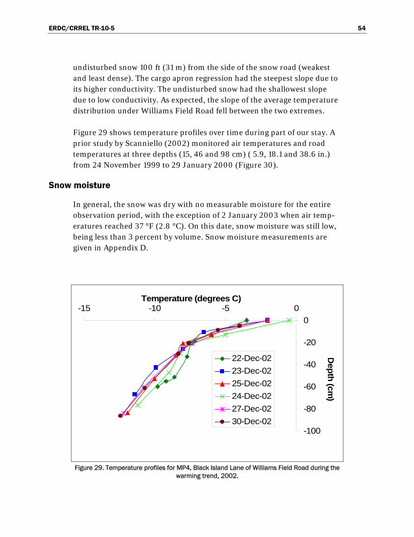
ERDC/CRREL TR-10-5 54
undisturbed snow 100 ft (31 m) from the side of the snow road (weakest and least dense). The cargo apron regression had the steepest slope due to its higher conductivity. The undisturbed snow had the shallowest slope due to low conductivity. As expected, the slope of the average temperature distribution under Williams Field Road fell between the two extremes.
Figure 29 shows temperature profiles over time during part of our stay. A prior study by Scanniello (2002) monitored air temperatures and road temperatures at three depths (15, 46 and 98 cm) ( 5.9, 18.1 and 38.6 in.) from 24 November 1999 to 29 January 2000 (Figure 30).
Snow moisture
In general, the snow was dry with no measurable moisture for the entire observation period, with the exception of 2 January 2003 when air temp-eratures reached 37 °F (2.8 °C). On this date, snow moisture was still low, being less than 3 percent by volume. Snow moisture measurements are given in Appendix D.
-100
-80
-60
-40
-20
0
-15 -10 -5 0Temperature (degrees C)
Dep
th (c
m)
22-Dec-02
23-Dec-02
25-Dec-02
24-Dec-02
27-Dec-02
30-Dec-02
Figure 29. Temperature profiles for MP4, Black Island Lane of Williams Field Road during the
warming trend, 2002.

ERDC/CRREL TR-10-5 55
0
5
10
15
20
25
30
35
16-Nov 26-Nov 6-Dec 16-Dec 26-Dec 5-Jan 15-Jan 25-Jan 4-Feb 14-Feb
Date
Tem
per
atu
re (
de
gre
es
F)
-18
-16
-14
-12
-10
-8
-6
-4
-2
0
2T
emp
era
ture
(de
gre
es C
)
Air
Depth = 0.5 ft (15.2 cm)
Depth = 1.5 ft (45.7 cm)
Depth = 3.2 ft (97.5 cm)
Figure 30. Temperatures on Williams Field Road measured over the full 1999-2000 season
(Scanniello and Crist 2003, personal communication).
Specific Experiments
Effect of Speed
Compaction versus Speed on Williams Field Road: These tests occurred on 3 January 2003. Air temperatures averaged -3 °C (26.6 °F) and snow surface temperatures ranged from -1° to +1 °C (30.2° to 33.8 °F). Very clear tire tread marks were visible when the surface was rolled using the pneumatic-tired load cart at the slowest speed (4 mph [6.4 kmph]). Some tread marks were visible at the middle speed (8 mph [12.8 kmph]), and no tread marks were visible at the highest speed (12 mph [19.2 kmph]) and the surface was disaggregated. Results are given in Table 3 and shown graphically in Figure 31. Although it is popularly stated that compaction is better at lower speed, our results indicated the higher density was achieved at the higher rolling speed (9% greater than at the low speed). This may be a function of temperature because warmer temperatures cause more plastic or viscous behavior in snow. Or, it may be the result of other confounding variables influencing the test. There are many reasons why road processing should occur at slow speeds (to minimize surface disturbance, reduce wear on the vehicle, etc.). Therefore, further study of this effect is suggested.

ERDC/CRREL TR-10-5 56
Table 3. Roller speed effect on density, Williams Field Road MP4, 3 January 2003.
Density (g/cc)
Number of Samples
Standard Deviation (g/cc)
Range (g/cc)
Depth Range (cm)
Mile Post 4, Erebus Lane, 1:00 PM
12 mph 0.532 6 0.0177 0.510-0.560 2-12
8 mph 0.496 8 0.0132 0.485-0.520 2-8
4 mph 0.479 8 0.0320 0.425-0.535 3-13
0.4
0.42
0.44
0.46
0.48
0.5
0.52
0.54
0.56
6.4 kmph (4 mph) 12.8 kmph (8 mph) 19.2 kmph (12 mph)
Speed
De
ns
ity
(g/c
m3
)
Figure 31. Effect of compaction roller speed on density. Data are the average and standard
deviation of 6 to 8 measurements for each speed.
Impacts of rolling and dragging
Three small experiments on the effects of rolling and dragging the snow roads were conducted on the 2nd and 3rd of January:
1. 2 January 2003 Pegasus Road – density and strength before and after rolling or Delta packing (Table 2, Figure B-8).
2. 3 January 2003 Pegasus Road – strength profiles before and after rolling and dragging (Figure 32).
3. 3 January 2003 Williams Field Road – strength profiles before and after rolling (Figure 33).

ERDC/CRREL TR-10-5 57
-50
-45
-40
-35
-30
-25
-20
-15
-10
-5
0
0 50 100 150 200 250 300 350 400
Ram Resistance (kgf)
Ave
rag
e D
epth
(cm
)
Cart Ruts, before dragging
Between Ruts, beforedragging
Cart Ruts, after dragging
Between Ruts, afterdragging
Figure 32. Effect of dragging on Pegasus Road rolled with pneumatic-tired load cart (note strong layer at 22 to 37 cm). Red lines are data taken before dragging, blue lines are after
dragging.
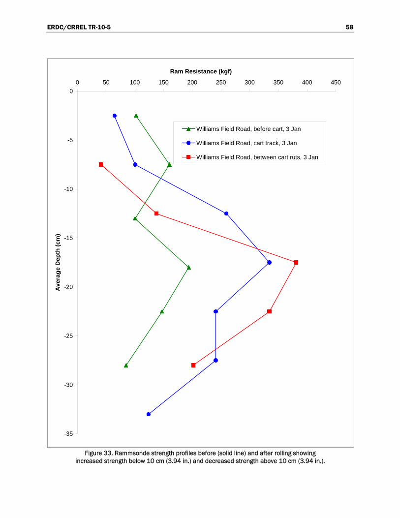
ERDC/CRREL TR-10-5 58
-35
-30
-25
-20
-15
-10
-5
0
0 50 100 150 200 250 300 350 400 450
Ram Resistance (kgf)
Ave
rag
e D
epth
(cm
)
Williams Field Road, before cart, 3 Jan
Williams Field Road, cart track, 3 Jan
Williams Field Road, between cart ruts, 3 Jan
Figure 33. Rammsonde strength profiles before (solid line) and after rolling showing
increased strength below 10 cm (3.94 in.) and decreased strength above 10 cm (3.94 in.).

ERDC/CRREL TR-10-5 59
Density changes from compaction processes tested on Pegasus Road are summarized in Table 2. These were performed on 2 January 2003 when the Black Island Lane was being rolled (using the pneumatic-tired cart with 3 blocks [19,000 kg or 42,000 lbs]). The lane was partially dragged prior to rolling. Meanwhile, traffic operated on the Erebus Lane while it was being trafficked with a smooth tired Delta. It was +2.8 ºC (37 ºF) and sunny in the morning, changing to cloudy, windy and cooler -5 ºC (23 ºF) in the early afternoon. Between two and six samples were collected for each condition. The following can be concluded from Table 2:
1. Delta packing increased the density by 20% (from 0.472 to 0.566 g/cc [29.5 to 35.3 lb/ft3]) at 5- to 10-cm (1.97- to3.94-in.) depth. This packing occurred while it was sunny and warm. Later in the day, the Delta packing smoothed the snow but did not increase the density.
2. Dragging the unprocessed snow increased the density by 12% (0.415 g/cc [25.9 lb/ft3] unprocessed to 0.466 g/cc [29.1 lb/ft3] when dragged) at 6- to 12-cm (2.36- to 4.72-in.) depth.
3. The dragging and rolling together increased the density by 23% (0.415 g/cc [25.9 lb/ft3] unprocessed to 0.507 or 0.510 g/cc [31.7 or 31.8 lb/ft3] beneath the load cart wheels) at 4- to 15-cm (1.57- to 5.91-in.) depth.
On 3 January 2003, the previously rolled Pegasus Road was dragged and Rammsonde measurements were taken before and after dragging. Measurements were taken both directly in the ruts and between the load cart ruts. The results are shown in Figure 32. Although there is some variability in the data, the load cart appeared to strengthen the snow beneath its ruts and even near the surface. The top surface (less that 7 cm [2.8 in.]), however, clearly looses strength just after the dragging process that occurred later that day. The cause for increased strength at approxi-mately 17 cm (6.7 in.) after dragging is unclear (perhaps an irregular icy lens, or being under the Challenger path).
Ram hardness was also measured before and after rolling on the Williams Field Road (Figure 33). The effect of rolling with the load cart is fairly clear in this figure; rolling increases the strength of the lower layers (at approxi-mately 12 to 30 cm [4.72 to 11.8 in.]), but reduces the surface strength (upper 10 cm [3.94 in.]). This agreed with visual and textural observations of the rolled surfaces.

ERDC/CRREL TR-10-5 60
Road use and maintenance observations
The McMurdo Station area snow roads were observed from 18 December 2002 to 10 January 2003. The first few days on-site included gathering measurement equipment, training, and making contact with appropriate representatives, etc. Soon after arrival, the weather turned stormy, which resulted in Condition 1 (no work or travel off Station) for several days.
Although our trip was near the middle of the austral summer season and we suffered weather delays at the outset, operations had not yet moved from the sea ice runway to Williams Field because the sea ice runway and ice road (particularly the transition) were in very good shape. Also, sche-duling conflicts with storms and holidays delayed the airfield move until December 26th and 27th (this normally occurs by 15 December). Early season trafficking on Williams Field Road was minimal because the airfield move was delayed. The two main lanes of the Williams Field Road were not opened to wheeled vehicle traffic until 28 December 2002 because of storms. The tracked vehicle lane was used by wheeled vans and wide-tired pickups as well as tracked equipment. Shuttle service to Williams Field commenced 29 December 2002 on the track lane and was moved to the vehicle lanes on 31 December 2002. The track lane deter-iorated very quickly under wheeled traffic, especially near the transition area (where the road subgrade changes from land to ice shelf). In both instances the wheeled vehicles created ruts (Figure 34).
We found that, though vehicles were requested to drive slowly when the roads were warm, the guidance was not followed or enforced. Low tire pressures were also requested for these conditions, but we found that tire pressures were not adjusted until after the staff noticed us checking them (a very effective motivator!). The vehicles that used the snow road are documented in Appendix E, providing gross vehicle weight, tire type and measured inflation pressures. We did not have methods to measure and record vehicle speeds but this would be useful in the future.
In general, the season was plagued by snow and wind events (Figure 35), and road construction and maintenance activities were challenged to pro-duce and maintain a robust transportation network. The road to Pegasus was not completed until the airfield’s scheduled opening, and thus had no time to sinter prior to supporting high traffic volumes and high vehicle weights. By contrast, during the same time that we were there, the LDB

ERDC/CRREL TR-10-5 61
launch pad was very carefully groomed and packed and then monitored during sintering for several days prior to use.
Figure 34. Measuring vehicle rutting from passenger vans and pickup trucks during
the austral summer warm season.
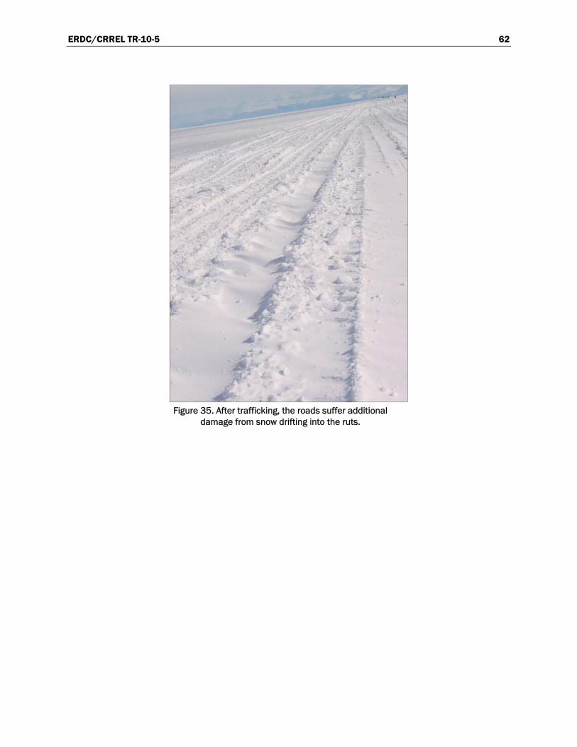
ERDC/CRREL TR-10-5 62
Figure 35. After trafficking, the roads suffer additional
damage from snow drifting into the ruts.
ERDC/CRREL TR-10-5 63
6 Field Work Summary
The data collected during our brief experience in snow road construction, maintenance and use can be summarized as follows:
1. Strength measurements show that the road is reasonably consistent along its length, with the inbound curve area being slightly weaker and the most outbound mile posts (MP4) being slightly stronger.
2. The Scott Base to ice shelf transition area has a very weak surface layer over a very strong layer at shallow (<20-cm [7.87-in.]) depth.
3. The Williams Field Road Track Lane is consistently stronger than the wheeled vehicle lanes
4. The LDB launch pad has a more consistent strength profile with depth, whereas the roads are weaker at the surface and stronger with depth.
5. The Williams Field Apron area contained the strongest snow that we measured.
6. Our data shows excellent agreement between different Rammsonde tools and different sized cones.
7. The Clegg surface strength on the snow roads was too weak to measure in many cases. The exception to this was the track lane, where we recorded the highest surface strengths.
8. Snow densities below 10 cm (3.94 in.) in depth averages approximately 0.6 g/cc (37 lb/ft3). This is the upper range that can be expected from compaction (without added heat).
9. Contrary to what was expected, higher rolling speeds (19 kmph vs 6 kmph [11.8 mph vs 3.7 mph] ) resulted in an approximately 10% higher snow density (0.532 vs 0.479 g/cm3 [33.2 vs 29.9 lb/ft3]).
10. Compaction by rolling with the pneumatic-tired load cart increased snow density by 23% but disaggregated the top 10 cm (3.94 in.) of snow. The increase in strength follows similarly (low surface strength and increased strength below 10 to 15 cm [3.94 to 5.91 in.]). Therefore, rolling should be followed closely by dragging and compaction of the road surface.
11. Dragging unprocessed snow can increase the density by 12%, and Delta rolling can increase the density by 20% under warm conditions.
With these results in mind, the following summarizes our observations in light of snow road construction, maintenance and use.

ERDC/CRREL TR-10-5 64
For the deeper layer, below 15-cm (5.91-in.) depth, densities approached or exceeded 0.600 g/cc (37.5 lb/ft3), which is the generally accepted upper limit achievable without the addition of water or heat (Abele 1990, RIL 2002). In all cases, the density of those layers exceeded 0.51 g/cc (31.9 lb/ft3), a value Abele indicated was acceptable for snow roads carr-ying low ground pressure vehicles. Thus, the roads we observed should provide adequate support for all but extremely heavy or concentrated loads. There is little reason to try to achieve further compaction of these deep layers.
Effectively recompacting previously processed snow requires that its bonds be broken (disaggregated) into fine particles. Rolling with the pneumatic-tired load carts, pulled by Challenger tractors, strengthened at depth but disaggregated the snow road to approximately 10-cm (3.94-in.) depth. We found that the disaggregation was not uniform and it left the snow in larger clumps rather than fine particles. These data indicate that snow should be immediately broken up (dragged or milled) and re-compacted after rolling or any other process that breaks up the sintered surface layer.
We did find that smooth tire rolling with the Delta appeared to be effective at compacting shallow layers of snow (top 5 to 10 cm [1.97 to 3.9 in.]) and may be a feasible choice for compacting small accumulations on the road surface. More significant snowfalls and drifts will benefit from rolling with the pneumatic-tired load cart or with a sheepsfoot roller to rebuild the road structure. An effective process includes dragging, and/or planing and dragging in tandem immediately after rolling. Final rolling of the loose surface with Deltas or other suitable equipment is required subsequent to dragging. Final sintering is required for “setup” after the rolling.
The age-hardening (sintering) process is more beneficial to dense snow, but the sintering process will only occur if the snow structure is left undis-turbed. If trafficked immediately after construction or maintenance, snow road bonds will fracture beneath tractor tracks, load carts or wheeled vehicles. Road construction efforts should avoid cutting (planing or dragging) the surface snow once it is compacted because they will reduce the strength of the road (Abele 1990).
Once the roads were open for traffic we found that, although vehicles were requested to drive slowly and at low tire pressures when the roads were
ERDC/CRREL TR-10-5 65
warm, this guidance was not followed or enforced. Although the vehicle dispatch certainly knew who was using the roads, no formal road use monitoring program was used, and no road condition monitoring was per-formed.
Based on a thorough literature review and our field observations, the following items summarize the most important aspects of construction, maintenance and operations of snow roads:
Construction quality control is the key determinate as to whether a snow road will ultimately succeed or fail.
Construction and maintenance must be executed with specific attention to detail and according to a well scheduled plan.
Compaction must immediately follow disaggregation. Dense snow yields more strength gain with age-hardening (Figure 2). Immediately compact fresh fallen snow. Allow age-hardening of 2 to 3 weeks. It is important to change the
perception of snow road building to reflect the fact that inactivity following construction and maintenance activities actually encourages strength gain.
Steep temperature gradients increase the effectiveness of age hardening. It is mandatory to use diurnal temperature regimes and sintering to construct a robust snow road network.
During the warmer portions of the season, when the snow near the surface is close to the thawing temperature, depth processing could have the additional benefit of cooling the snow mass near the surface by mixing it with the colder snow below and thus increasing the ability of the snow near to surface to harden.
When possible, limit vehicle types (tracks) and operations according to temperatures.
Temperatures greater than -40 °F (-40 °C) and less than 25 °F (4 °C) are best for hardening.
Low impact tires should be used.
Several of these guidelines are known and some are implemented at McMurdo, but there is no formal structure for assessment and monitoring the use and condition of the roads to gauge proper maintenance. In light of current thinking to combine airfields at a single site, and associated with that the potential for a significant increased in the use of snow roads, the

ERDC/CRREL TR-10-5 66
time for implementing a formalized snow road construction, maintenance and use program is on the horizon.

ERDC/CRREL TR-10-5 67
7 Opportunities for the Future
Much has changed since the last formal snow road studies were performed in the 1970’s. Modern construction equipment, over snow vehicles, low impact tires, and experiential snow road techniques contribute to a vastly different snow road paradigm. Although our literature review detected few new basic and experimental research projects on snow compaction and strength, field projects have demonstrated improvements in snow foun-dation design. Additionally, researchers have made significant strides in snow mechanics (Shipiro et al. 1997) and in numerical modeling tech-niques on snow compaction and metamorphism (Hopkins 2004, Shoop et al. 2006, Kaempfer and Schneebeli 2007). Together, these could be used to provide specific guidelines on the relationships between temperature, density and hardness for different snow types and construction methods.
Based on findings discussed in this report, it is clear that the McMurdo snow road network could benefit significantly by integrating snow road construction best practices. Additionally, it could further benefit from new construction techniques and materials documented herein that require full-scale field testing to prove-out their potential. These findings are esp-ecially important in light of the USAP’s consideration to consolidate the McMurdo airfields to a single site. An airfield consolidation concept would be wholly dependent on a 100% reliable snow road and land-ice shelf transition. A formal snow road design, test and monitoring program completely meshes with the McMurdo Consolidated Airfields Basis of Design and the McMurdo Transportation Study, both of which are cur-rently active projects. It is very likely that this project would result in a more robust road network that requires less equipment, time and money (per lane mile) than the current informal construction and maintenance processes.
Thus, looking toward the future, we recommend the following be considered:
1. Preliminary Study: Conduct a preliminary study to establish the design requirements for a modern snow road construction and maintenance program. The need and durability of this network should be guided by the McMurdo Consolidated Airfields Basis of Design augmented by the

ERDC/CRREL TR-10-5 68
McMurdo Transportation Study. This study will include stakeholders (e.g. NSF, Air Force, Air National Guard, USAD prime contractor [currently Raytheon Polar Services Company {RPSC}]), and will; determine perfor-mance requirements, document shortcomings of the current road net-work, document statistics and information related to construction and maintenance of the existing system, and conduct a preliminary analysis of the cost and benefits of implementing a formal snow road construction program. In parallel, a road use policy needs to be developed including a vehicle monitoring program, best practices for road use, and methodology for monitoring road conditions. This preliminary study should also consider the impacts of climate change on the transportation network alternatives.
2. Phase I and II - Proof of Concept: Develop a construction, maint-enance and monitoring program that includes full-scale evaluations of pre-determined construction techniques and feasibility testing of alternate construction techniques (such as wood chips, snow millers) for both the snow road and the land-ice transitions. The road use and condition moni-toring program will evolve in conjunction with the McMurdo Transport Study, including a test plan to generate relationships between vehicle weights and contact pressure with snow road strength. Phase II would complete the Phase I work and generate guidelines similar to an Air Force ETL on the proper construction, maintenance and monitoring methods for snow roads.
3. Phase III - Operational Road Network: CRREL will work with NSF and the designated support contractor (currently RPSC) on construction, maintenance and monitoring of a modern snow road system. Final testing and certification will be obtained.
ERDC/CRREL TR-10-5 69
8 References
Abele, G., and A. F. Wuori. 1962. Supporting capacity of processed snow runways, Hanover, NH: U.S. Army Cold Regions Research and Engineering Laboratory.
Abele, G. 1963. A correlation of unconfined compressive strength and ram hardness of processed snow. Technical Report 85. Hanover, NH: U.S. Army Cold Regions Research and Engineering Laboratory.
Abele, G. 1990. Snow roads and runways. Monograph 90-3. Hanover, NH: U.S. Army Cold Regions Research and Engineering Laboratory.
Adam, K. M., and H. Hernandez. March 1977. Snow and ice roads: Ability to support traffic and effects on vegetation. Arctic, 30(1):13–27.
Alger, R. 2008. Personal communication, Houghton, MI: Snow Research Institute, Keweenaw Research Center, Michigan Tech University.
Alger, R. G. 1993a. The effect of grain size and compaction on snow strength. Contract Report. Hanover, NH: U.S. Army Cold Regions Research and Engineering Laboratory.
Alger, R. G. 1993b. A new concept in trail grooming, Contract Report. Lansing, MI: The KRC Groomer, Michigan Department of Natural Resources.
Barber, M., and R. L. Brown. 1993. Theoretical and experimental results of using binders for snow roads and runways in Antarctica. Special Report 93-17. Hanover, NH: U.S. Army Cold Regions Research and Engineering Laboratory.
Barthelemy, J. L. 1975a. Snow road construction by layered-compaction–Construction and maintenance guide. Technical Report R 819. Port Hueneme, CA: Naval Facilities Engineering Command.
Barthelemy, J. L. 1975b. Snow road construction–A summary of technology from past to present. Technical Report R 831. Port Hueneme, CA: Naval Facilities Engineering Command.
Blaisdell, G. 1991. Personnel and cargo transport in Antarctica: Analysis of current U.S. transport system. Rpt 91-5. Hanover, NH: U.S. Army Cold Regions Research and Engineering Laboratory.
Blaisdell, G., V. Klokov, and D. Diemand. 1995. Compacted snow runway technology on the Ross ice shelf near McMurdo, Antarctica. Contributions to Antarctic Research IV, Antarctic Research Series. 67:153–173.
Diemand, D., R. Alger, and V. Klokov. 1996. Transportation Research Record: Journal of the Transportation Research Board. Snow Road Enhancement 1534:1—4.
Diemand, D., and V. Klokov. 2001 A method for producing fine-grained ice from snow by compaction. ERDC/CRREL TR-01-12. Hanover, NH: U.S. Army Cold Regions Research and Engineering Laboratory.

ERDC/CRREL TR-10-5 70
Drope, M. 1977. Arctic Snow Roads for Arctic Pipeline Construction–A Canadian Arctic Gas Project. Symposium on Tracks or Wheels. June 3-4, 1976. Calgary, Alberta: Canadian Society for Terrain Vehicle Systems.
Gow, A. J., and R. O. Ramsier. 1964. Age hardening of snow at the South Pole. Research Report 112. Hanover, NH: U.S. Army Cold Regions Research and Engineering Laboratory.
Hopkins, M. 2004. Discrete element modeling with dilated particles. Engineering Computations 21:422-430.
Jacka, T. H., and W. F. Budd. 1998. Detection of temperature and sea ice extent changes in the Antarctic and southern ocean. Annals of Glaciology 27:553-559.
Johnson, P. R. 1979. Snow and Ice Roads in the Arctic. In Proceedings Conference on Applied Techniques for Cold Environments, Anchorage, Alaska, May 17-19, 1978. 2:1063–1071. New York, American Society of Civil Engineers. Report No: MP 1223. U.S. Army Cold Regions Research and Engineering Laboratory.
Joint Snow Compaction Program. 1954. Report on Snow Compaction Trials 1952-1953. Canada, Defence Research Board, Defence Scientific Information Service Document L7167.
Jones, P. D., and P. A. Reid. 2001. A databank of Antarctic surface temperature and pressure data. ORNL/CDIAC-27, NDP-032. Oak Ridge, TN: Carbon Dioxide Information Analysis Center, Oak Ridge National Laboratory, U.S. Department of Energy.
Kaempfer, Th. U., and M. Schneebeli. 2007. Observation of Isothermal Metamorphism of New Snow and Interpretation as a Sintering Process, J. Geophys. Res., 112.
Lee, S. M, W. M. Haas, R. L. Brown, and A. F. Wouri. 1989. Improving snow roads and airstrips in Antarctica. Report 89-22. Hanover, NH: U.S. Army Cold Regions Research and Engineering Laboratory.
Lefebvre, L.M. 1979. Winter Roads and Ice Bridges. Civil Engineering-ASCE 49(12):54–57.
Moser, E. H. 1954 Experimental Arctic Operation Hard Top 1. Technical Report R-006. Port Hueneme, CA: Naval Civil Engineering Laboratory.
Moser, E. H. Jr. 1971. Roads on Snow and Ice. Proceedings of the International Symposium on Cold Regions Engineering I:155–169. American Society of Civil Engineers and University of Alaska.
Naval Civil Engineering Laboratory (NCEL). 1967. Compacted-snow runways in Antarctica – Limitation of contaminated snow, Port Hueneme, CA: Naval Facilities Command.
Naval Civil Engineering Laboratory (NCEL). 1972. Snow road–Construction and maintenance manual. Port Hueneme, CA: Naval Facilities Command.

ERDC/CRREL TR-10-5 71
Ramsier, R. O., and G. W. Sander. 1965. Sintering of snow as a function of temperature. International symposium on scientific aspects of snow and ice avalanches, Davos, Switzerland. (Also CRREL Research Report 189, 1966.)
Rakennusinsinoorien Liitto (RIL). 2002. Snow Construction–General rules for design and construction. RIF 218-2002, Helsinki, Finland: Association of Finnish Civil Engineers RIL.
Russell-Head, D. S., and W. F. Budd. 1989. Compacted-snow runways Guidelines for their design and construction in Antarctica. Special Report 89-10. Hanover, NH: U.S. Army Cold Regions Research and Engineering Laboratory.
Scanniello, J., and Crist, G. 2003. Personal Communications. McMurdo Station, Antarctica.
Seman, P. In prep. McMurdo Transportation System Study. ERDC/CRREL Report in preparation.
Shapiro, L. H., J. B. Johnson, M. Sturm, and G. L. Blaisdell. 1997. Snow mechanics: Review of the state of knowledge and applications. Report CR 97-03. U.S. Army Cold Regions Research and Engineering Laboratory.
Shoop, S., K. Kestler, and R. Haehnel. 2006. Finite element modeling of tires on snow. Tire science and technology 34(1):2–37.
Snow Ice and Permafrost Research Establishment (SIPRE). 1954. Summary of snow compaction tests. Special Report 7. 1952-53, Kapuskasing, Canada, Wilmette, IL: Field Operations and Analysis Branch.
Thomas, M. W., and K. D Vaudrey. 1973. Snow road construction technique by layered-compaction of snowblower processed snow. Technical Note N-1305 Port Hueneme, CA: Naval Facilities Engineering Command.
United States Air Force. 2007. Design, construction, maintenance, and evaluation of the McMurdo Sound (Antarctica) Sea Ice Runway for heavy wheeled aircraft operations. Engineering Technical Letter (ETL) 07-12. Tyndall Air Force Base, FL: AFCESA/CES.
Weller, G., 1998. Regional impacts of climate change in the Arctic and Antarctic. Annals of Glaciology. 27:543-552.
Wouri, A. 1965. Testing of a vibratory snow compactor. Special Report No. SR 55. 11. Hanover, NH: U.S. Army Cold Regions Research and Engineering Laboratory.
ERDC/CRREL TR-10-5 72
Appendix A: Navy Technology and Guidance
Evolution of Navy snow road technology
The bulk of Navy snow compaction experience was derived from research conducted in the Antarctic. In the spring of 1960, the staff construction officer at McMurdo Station requested NCEL to investigate the practi-cability of building roads on snow-covered sea-ice to improve the trans-portation between McMurdo Station and the air-support facilities. In the fall of 1960, a 25-feet (ft) (7.62 m) wide, 4-mile (mi) (6.4 km) long snow road was constructed over the ice between McMurdo Station and the sea-ice runways at Williams Field. At that time, Williams Field was located about 3 mi (4.8 km) out on the McMurdo Sound. The first offshore mile of snow road was constructed on bare ice and the next 3 miles were cons-tructed on a 4-ft (1.2-m) snow pad. Construction included pre-compaction, double depth-processing, compaction and surface hardening. A ten-man team of Seabees constructed the roadway with two snow tractors, two model 24 snow mixers, two snow-compacting rollers, one model 80 snow plane, one finishing drag, and one surface-hardening roller. The road was used continuously for a 10-day period in November by all types of wheeled vehicles, including 30-ton tractor-trailer rigs.
The completed roadbed was depressed about 10 in. (25.4 cm) below the natural terrain, which accelerated drift accumulation. The drift snow was windrowed to the road edges following each storm, and produced 2 ft (61 cm) high berms along each side of the road. The roadway was aban-doned in mid December after a 3-day blizzard filled it with snow. The project demonstrated the feasibility of vehicle roads on snow in Antarctica, and also demonstrated the need to elevate snow roads above the surr-ounding terrain.
Barthelemy (1975b) presented a brief year-by-year review of the progress in Antarctic snow road technology. He comprehensively described the Navy procedures for construction and maintenance developed and used by the Navy during the 1960s and early 1970s. The initial snow road was constructed in 1960. In 1962 a small, self powered, track mounted Peter Junior Snow Miller was used to cast snow for a 200 ft (61 m) wide by 300 ft (91 m) long test pad. The following year a large Sicard model BK Snowmaster truck-type rotary snowplow was tested by building a 170 ft
ERDC/CRREL TR-10-5 73
(52 m) wide by 2,000 ft (610 m) long section of compacted snow runway. Snow intake efficiency was limited by the pitch and roll of the mounted tractor. As a result, a special model 40 snowplow carrier was fabricated to carry the model BK snow plow. It was successfully tested near McMurdo Station during the summer of 1964 and 1965.
The model 36/42 snow mixer was introduced to Antarctica during the 1964 summer season. Extensive tests were conducted during the 1965 Austral summer. Two experimental snow road sections were constructed by NCEL in 1965 to better establish minimum strength requirements on deep snow for vehicle-weight and tire-pressure combinations up to 70,000 lbs (31,751 kg) and 30 psi (207 kPa), respectively. One road section, paved with snowplow-blown snow, was elevated 2 ft (61 cm) above the undisturbed snow surface. The other section was paved by depth-processing the natural snow to a depth of 16 in. (41 cm) using the model 36/42 snow mixer, followed by compaction rolling. The test section was depressed about 8 in. (20 cm) below the surrounding terrain. The density of the virgin snow at the site of the two test section was 0.36 g/cc (22.5 lb/ft3). The density of the completed blown-snow pavement was 0.51 g/cc (31.8 lb/ft3), and the mixer snow pavement was 0.57 g/cc (35.6 lb/ft3).
In 1966, NCEL perfected the two-pass tailgate methods where one model 36/42 snow mixer follows directly behind a lead mixer. This technique reduced the total number of passes required during mixing and resulted in greatly decreased processing time. Another improvement was the intro-duction of the model 1000 snowplow carrier in 1968. That unit had a greater snow transport capacity than its predecessor, the model 440 snow-plow carrier. The model 1000 carrier assumed a fully operational status following a successful field trial during the summer of 1969.
A dual drum snowpaver was sent to McMurdo Station in 1971. It sustained damage in transit, and the rear rotor hydraulic system was contaminated. Thus, only limited tests were conducted. A technical representative from the manufacturing company was sent to the field site in 1972, but was unable to solve the contamination problems.
In 1973, a 1-mi (1.6-km) experimental road section was constructed using layered-compaction techniques. No snow mixers were used. Instead, the model 1000 snow transporter, carrying a modified cutting-head assembly with eight helical blades, was used to gather, pulverize, and deposit the

ERDC/CRREL TR-10-5 74
snow material. The deposited snow was spread as individual 4-in. (10-cm) layers and compacted to a thickness of 20 to 24 in. (51 to 61 cm). Test results showed that snow density and shear strength comparable to roads built by pulvimixing.
NCEL recommended construction techniques
Barthelemy (1975a) indicates that all snow roads are sensitive to quality control. To achieve and maintain a durable road of consistent strength and quality, construction and maintenance efforts must be executed according to detailed procedures. Special attention to detail frequently determines the difference between a functional road and an impassable quagmire during the peak temperature summer months. Two methods of const-ruction for elevated snow roads were developed by NCEL.
Layered-compaction
Layered-compaction is the most recent technique NCEL developed to minimize the number of operators and equipment required. It involves elevating the pavement to a desired height by compacting successive 4-in. (10-cm) layers of snow without using snowmixers. A rotary snowplow is used to gather, process, and deposit the snow material. The recommended basic equipment and construction procedures are summarized below.
Equipment:
1. Tracked personnel and cargo carrier 2. LGP D8 tractor (four required for optimum construction) 3. LGP D4 tractor with angle blade 4. Ski-mounted snowplow or snowblower 5. Snow Plane, 40- or 80-ft (12.2- or 24.4-m) model 6. Pneumatic-tired, wobbly wheel roller 7. Eight-foot (2.4-m) diameter steel roller 8. Timber drag 9. Large rubber-tired tow vehicle
Procedure:
1. Select and stake the roadbed site. 2. Compact and level the roadbed. 3. Deposit and shape snow along side of road for containment berms.

ERDC/CRREL TR-10-5 75
4. Elevate to grade by compacting successive 4-in. (10-cm) layers of snow blown onto the roadbed.
5. Level, finish, and age-harden.
It is essential to deposit, spread, and compact each 4-in. (10-cm) layer during a single work shift. A new road may be built in sections to realize this requirement. This construction method produces a finished pavement that is at least 30 ft (9.1 m) wide and elevated 24 to 30 in. (61 to 76 cm) above the surrounding terrain.
Thomas and Vaudrey (1973) presents the development of this procedure, and Barthelemey details this construction method in his construction and maintenance guide. Some of Barthelemy’s key points are presented below.
Site selection: Avoid sharp curves for construction ease and traffic considerations. A minimum radius of 1,000 ft (305 m) is recommended. Choose a level surface with as few pressure ridges, depressions or other obstacles (i.e. old berms or drift areas) as possible.
Roadbed staking: Stake both edges of the roadbed with alignment stakes to indicate proper width and grade stakes to indicate proper finished surface elevation (24 to 30 in. [61 to 76 cm]).
Roadbed preparation: Prior to snow placement, the road bed should be packed and leveled to form a compacted snow-mat of uniform strength. At least nine passes should be made by an LGP D8 tractor pulling an 8-ft (2.4-m) diameter steel roller weighted with 2,000 lbs (13,790 kg) of ballast. The compacted area should then be leveled and recompacted using the LGP D8 tractor without the steel roller.
Depositing containment berms: The ski-mounted rotary snowplow is the primary mover of snow. It is the only piece of equipment used in snow road construction by layered-compaction that is unique and can not be replaced with a substitute. The snowplow, as modified, consists of a rotary cutting head equipped with eight helical cutting blades that cut the snow and mechanically force it into an impeller. The snow is then discharged through a directional spot-casting chute. This chute is hydraulically controlled and permits accurate placement of the snow on the surface to be elevated.

ERDC/CRREL TR-10-5 76
The snow blower, pulled by an LGP D8 tractor, deposits snow as it makes multiple passes along each side of the snow road. The first pass on each side is used to construct containment berms. The snowplow is pulled at approximately 60 ft (18.3 m) per minute just outside of the alignment stakes, depositing snow in a windrow just inside the stakes. The snow blower engine speed is between 2,400 and 2,800 rpm in low gear during operations. A LGP D4 tractor with an angled blade follows the snow blower to straighten the containment berm walls and level them to the recommended 24- to 30-in. (61- to 76-cm) height.
Road elevation: Each 4-in. (10-cm) snow layer requires a pass along each side of the roadbed. The snow is collected from contiguous zones paralleling the roadbed so that ditches (called borrow pits) are formed along each side. Each barrow pit is three rows wide, and each row provides two “cuts,” one atop of the other. Figure A1 illustrates the sequence of cuts to be made. The inside and outside rows of the borrow pit, each approx-imately 6 ft (1.8 m) wide, are separated by 2 ft (61 cm). The middle row is narrower because the modified snow blower cannot throw snow over the containment berms to the center of the road if the outside row is spaced out farther. When the snow road is completed, each borrow pit is approx-imately 1-1/2 to 2 ft (45.7 to 61 cm) deep and 16 ft (4.9 m) wide.
Figure A1. Cross section showing sequence of passes for elevating snow roads with a
snowblower (Barthelemy 1975a)
The snowplow must be operated in high gear at an engine speed between 2,400
and 2,800 rpm. Pilot the tow LGP D8 tractor in low gear at an engine speed between 600 and 800 rpm. This mode nets a construction speed of approximately 90 ft (27.4 m) per minute. Blown snow shall be deposited at the middle of the road to facilitate even spreading between the centerline and containment berms. It is impossible to blow snow from the outside row

ERDC/CRREL TR-10-5 77
and deposit it as a windrow along the road centerline because the high velocity of the processed snow causes it to spread toward the containment berm at the far side of the road. Therefore, the best procedure is to aim the blown snow at a central section of the road nearer the snow blower.
Leveling: The leveling equipment should trail directly behind the snow blower and spread the snow over the roadbed in a thin, even layer no thicker than 4 in (10 cm). The most common piece of equipment used for leveling is an 80-ft-long (24.4-m) snow plane towed by a crawler tractor. The snow plane is mounted on skis. The rear skis are hydraulically steered by the operator and the front skis are steered through the tow vehicle’s drawbar. The plane’s blade is hydraulically raised and lowered and can be pivoted for grader operations. The blade is equipped with detachable wings that are used for leveling operations; these wings can be removed quickly when the grader configuration is required. Substitutions are pos-sible for this operation: a 40-ft (12.2-m) snow plane may replace the longer model, and a LGP D8 can be used as the tow vehicle.
Layered-compaction: D8 tractors are used to compact each newly leveled snow layer. Walk the tractors over the roadbed so that the entire surface is covered by at least three passes. Once layered-compaction is complete, the road shall be finish-leveled with the 80-ft (24.4-m) snow plane. Remove all excess berm material above the level of the road and at the outer edges of the road.
To produce a quality snow road of consistent strength, procedures to blow, level, and compact a 4-in. (10-cm) layer must be completed during a single work shift. Construct the road in sections such that the available equip-ment and work force can meet this requirement.
Snow hardening: The final step in layered-compaction construction is to provide a strong mat that will resist damage from the wheeled vehicular traffic by hardening the top 4 in (10 cm) (wear surface). Wait at least three days after all other procedures have been completed before starting surface-hardening procedures. With the 13 smooth, pneumatic tires inflated to 45 psi (310 kPa), weight the bed of the wobbly wheel roller to approximately 4 tons (3,629 kg) with steel material. Make at least three passes over the entire roadbed surface and then finish-smooth using a timber drag. The wobbly wheel roller and the timber drag must be towed by a rubber-tired vehicle, preferably a 1-ton (907-kg) pickup. The road

ERDC/CRREL TR-10-5 78
should be sufficiently hardened to prevent the tires of the wobbly wheel roller from cutting deep furrows into the compacted material. The road should be ready for normal traffic on the fourth day.
Construction of transition areas: The sections of a completed snow road must be interfaced smoothly. Each transition is actually an overlap between neighboring sections. Overlap is a necessary consequence of equipment movement; the snow blower and snow plane must turn around and reposition for a new pass each time they complete a return pass.
Figure A2 illustrates a typical turnaround configuration. After the snow blower completes a rerun pass alongside the unfinished road section under construction, it must be pulled over the road and repositioned on the opposite side. Similarly, the snow plane must be angled off the unfinished section, turned around, and angled back onto the road. Access ramps to allow equipment off and on the road section must also be constructed.
Figure A2. Turn around scheme for reposition snowblower and snowplane
(Barthelemy 1975a).
Depth-processing
The alternative method of snow road construction is depth-processing. The same basic construction equipment is required, with the addition of
ERDC/CRREL TR-10-5 79
two snow mixers. Although less desirable, one mixer can be used. Unlike the layered-compaction technique, the rotary snowplow is not an essential item when depth-processing snow. The snow can be pushed onto the road-bed using bulldozers. Therefore, in situations where a snowplow is not available, depth-processing is preferred. However, Barthelemy (1975b) indicates that this method requires specially built, ski-mounted snow mixers, and is critically sensitive to quality control during construction.
Snow road construction using depth-processing is summarized below.
Procedure:
1. Select and stake the roadbed site. 2. Deposit snow on roadbed using rotary snowplow or bulldozers. 3. Level with 40- or 80-ft (12- or 24-m) snow plane. 4. Depth-process using snow mixers. 5. Re-level, finish, roll and age-harden.
The detailed process for depth-processing is documented in the Snow Road – Construction and Maintenance Manual (NCEL 1972) and is summarized below.
Site selection and roadbed staking: The process for these first two steps is much the same as for layered-compaction construction, with only minor variations in distances between and heights of stakes suggested.
Road elevation: Depositing snow to elevate the road surface is accom-plished with either a rotary snow plow or bulldozer. A ski-mounted, four blade, rotary snow plow with a capacity of 1,000 tons (907,186 kg) per hour is towed by an LGP D8 tractor. A pattern of passes similar to that used during layer compaction is used to deposit snow on the road bed (Figure 4). A finished elevation from 2-1/2 to 3 ft (76 to 91 cm) above the starting surface should be deposited before the road surface is rough-graded using a bulldozer blade. The rough-grading process should take place before the snow begins to harden (within an hour) because once sintering begins, the bulldozer will leave big chunks of snow on the surface.
One of the main advantages of the rotary snow plow method is that it pro-duces uniform and consistent material, which will result in a stronger

ERDC/CRREL TR-10-5 80
snow road. A bulldozer may be used if a rotary snowplow is not available. Since it is more difficult and time-consuming to construct a straight road using a bulldozer, the marker and grade stakes should be spaced closer together to maintain alignment.
Material moved by bulldozers may contain large chunks of hard snow. This condition makes leveling and mixing more difficult than with a rotary snow plow. Travel speed must be adjusted during the first mixing operation to compensate for varied material.
Leveling: After the road has been elevated and rough-graded with a dozer blade, finish leveling is required to obtain a smooth, finished road because the snow mixers will not level out contours or uneven surfaces; they tend to amplify them.
The equipment required for finish leveling is a modified 80-ft-long land plane towed by a D4 or D8 crawler tractor. The snow plane is ski mounted, and several passes are required to level the road surface prior to mixing.
Mixing: After the snow is deposited and rough leveled, the snow must be pulvimixed and compacted to produce a road that will support heavy wheeled vehicles. Ski-mounted pulvimixers, similar to those used to compact earth-fill roadbeds for asphalt or concrete highways, are used in this most critical step. The rotor, spinning at high speed, breaks up the snow particles under a cover or hood that prevents snow from scattering and redepositing at the trailing edge of the cover.
A steel rear ski, the same width as the mixer rotor, compresses the freshly mixed snow. There are two methods of mixing recommended; the two-mixer, tailgate method and the two-pass single mixer method. Since a second pass is required when the two-pass method is used, the second pass should be accomplished as soon as possible after the first. The two mixing methods are described in detail in the Snow Road - Construction and Maintenance Manual (NCEL 1972)
Releveling: After mixing, another leveling operation with the snow plane is required. The rear drag ski of the mixer leaves 8- to 10-in (20.3 to 25.4-cm)-high berms at the edges of each pass. This material should be spread over the surface and used to fill any low spots. Excess material at the road edges should be bladed over the sides so that the roadbed

ERDC/CRREL TR-10-5 81
remains level. This step should be accomplished as soon after the final mixing pass as possible, because the berm material will harden and be difficult to spread if left for any length of time.
Rolling: The loose berm material spread by the snow plane should be consolidated with the other mixed snow after leveling. This involves rolling the roadbed with a LGP D8 tractor towing an 8-ft (2.4-m)-diameter smooth steel roller. The heavy tractor compacts the mat while the roller finishes the surface. At least six overlapping roller passes should be made, with the overlap equal to one half the roller widths. This rolling should immediately follow the mixing and releveling.
Surface hardening: Is the same as for the layered-compaction method.
Surface transition areas: Transition areas, where the snow road meets and interfaces with dirt areas, bare ice, or ice with minimal snow cover, are more sensitive to particular problems such as melting, surface runoff and drifting. In addition, ice cracks can become wide enough to hinder wheeled vehicles. The areas where snow abuts land are an additional topic discussed in the NCEL 1972 Snow Road - Construction and Maintenance Manual for depth-processed roads.
Several methods are available to construct and maintain these areas in a way that will prevent these problems.
Building ramps to clear tidal cracks: Where ice and snow fields connect with land, tidal action and ice movement cause cracks in the ice. These cracks are small at times but can become wide enough to hinder transportation. For example, tires get stuck in the cracks, springs break, or cargo may dislodge from trucks. Wooden ramps can be constructed to bridge these areas and permit uninterrupted transportation.
Apply dirt overlay on area with minimal snow covering: Ice areas close to land usually have a minimal snow cover, and in such areas it is difficult to obtain enough material to build and maintain snow roads. In such cases, a dirt overlay 16 to 20 in (40.6 to 50.8 cm) thick can be placed until enough snow is available to elevate and compact the road. The thick dirt layer will insulate the ice to avoid or delay melting.

ERDC/CRREL TR-10-5 82
Use a culvert drain and a rock base: In areas where elevated snow roads connect with land, there is usually runoff water from melting snow. If this runoff is near the road system, steps should be taken to minimize washout or undermining of the roads. Culvert drain pipes can be used to control flow, and a rock base for the road in low sections near runoff areas will protect the road from damage and minimize maintenance.
Provide a road extension: Dirt tracked by vehicles from land to ice or snow accelerates surface melting and produces potholes. To help control this, a timber or concrete (or tire mat) road 50 ft (15.2 m) or longer at the end of the dirt road can be used to catch dirt and mud dropped from the underside of vehicles. New snow deposited at frequent intervals in a thin layer over the dark area will help reflect solar radiation and prevent damage. These areas usually form ice when temperatures drop below freezing. Even though they are still dark, they will support heavy wheeled traffic.
Navy maintenance procedures
Properly constructed high-strength snow roads should support traffic throughout the Antarctic summer season (NCEL 1972). However, the strength and durability of the road depend on temperature; and high temperatures and solar radiation are prevalent during the midsummer season. As the temperature of snow rises, the snow becomes weaker and softer and is damaged easily by heavy traffic of wheeled vehicles. Surface damage is greater if vehicles are operated with high tire pressures. Peri-odic maintenance is required to keep snow roads in usable conditions. The high maintenance months for snow roads in Antarctica are December and January. Proper timing is essential and daily surface maintenance is required during these months.
Ordinarily, conscientious, routine maintenance is sufficient to maintain snow roads. However, timing and prevention are vital for effective maint-enance. If proper procedures are not followed in time, major road repairs will probably become necessary. The following section describes measures for routine road maintenance and also the steps required to affect major road repairs should they become necessary. These techniques apply to snow roads constructed by both the layered-compaction and the depth-processing methods.
Routine maintenance: The three major maintenance problems on high-strength snow roads are drifting, rutting, and the formation of

ERDC/CRREL TR-10-5 83
potholes. The transition areas where the snow road abuts the land also pose particular maintenance problems.
Drifts: Drifting is usually minimal on elevated roads. When drifting does occur, it is most likely caused by poor maintenance. Berms left at the road edge during maintenance provide snow for drifts during storms or high winds. This problem can be avoided by taking two simple steps:
1. Windrow excess snow to the center of the road during maintenance operations.
2. Blow this snow off the road with a rubber-tired rotary snow plow.
Finger line tapering drifts (finger drifts) will form in some places on smooth, elevated roads during storms. Although these finger drifts do not normally make a road impassable, they will harden if left for any length of time and produce an extremely rough road surface. Roads should be dragged with the rough drag to immediately spread the snow over the surface in a thin layer after a storm. Subsequent wheeled traffic will compress the snow. Dragging has the additional benefit of covering dirty spots and protecting the road to a large extent from solar radiation damage. It is worthwhile to point out again that drift control, like all road maintenance, requires prompt action. If the road is neglected too long, major repairs will be required.
Ruts: Ruts are primarily linear depressions formed by vehicle traffic on the roadbed when the snow loses its strength because of high temperatures and solar radiation. The snow surface melts and softens so that wheels cut into the surface. Equipment operators tend to follow these ruts, and this continual traffic over the same track eventually deepens the ruts until the road is severely damaged or completely wrecked. Many ruts can be prevented by taking the following steps:
1. Remove visible traces of ruts as soon as possible to discourage operators from following the ruts.
2. Instruct equipment operators to vary their driving patterns and not to follow in the same tracks when possible.
3. Do not allow tire pressure on wheeled vehicles to exceed 30 psi (206.8 kPa) for the 20-ton (18,144-kg) truck-tractor and trailer combi-nation and 10 psi (68.9 kPa) for the W300 pickups.

ERDC/CRREL TR-10-5 84
When ruts do form, however, corrective maintenance can be performed. The necessary repair equipment depends on the rut depths. For shallow ruts, the rough drag followed by the smooth drag will usually repair the road surface. If the road has been neglected too long, a standard road grader must be used to repair the deeper ruts. Tire pressures on the grader should be kept as low as possible on snow roads.
In addition, the following guidelines should be observed when eliminating ruts by corrective maintenance:
1. The snow should be moved and leveled rather than cut deeply. Cutting the mat will thin the compacted snow and weaken the road.
2. Any excess material should be windrowed to the road center and removed with the rotary snow plow. Pushing it to the side of the road will cause drifting.
3. In the warmest times of the operating season, the road should be surfaced with the smooth drag after grading. This will help force the moisture into the snow mat and also will present a smooth white, reflective surface to the sun, helping alleviate solar radiation damage.
4. Drift or berm material that collects around marking stakes and flags during maintenance should be knocked down with a shovel to eliminate drift potential.
Potholes: Potholes are small singular, often circular depressions and can form in the roadbed in two ways:
1. If dirt and oil are left on the road surface, solar radiation will weaken the snow so that a hole can form.
2. Soft or rough spots in the road that are impacted by wheels time after time will form increasingly deeper holes. If left unrepaired, these potholes could damage tires and/or axles.
When temperatures are at or below freezing, the quickest and best method for repairing potholes is to fill the hole with ice chips and spray a small amount of water over the patch. The water will freeze and bond the ice chips into the hole, giving a long lasting patch. Ice chips can be obtained from an area of sea ice with an ice chipper. Water can be sprayed by hand from drums.

ERDC/CRREL TR-10-5 85
Transitions: Any area the snow abuts the land requires the heaviest maintenance. Severe conditions detrimental to the snow roads are found in these areas. Providing the proper transition areas will help to minimize these problems, but routine maintenance is still necessary.
Major Road Repairs: On occasion, a road may deteriorate so badly in certain areas that filling with ice chips, grading, or any other maintenance procedure is not sufficient to repair the damage. More drastic measures are necessary. If the deteriorated section is large, the snow blower should be used. The procedure is the same as that used in the road’s construction. First, containment berms are constructed and snow is deposited in 4-in (1o-cm) layers. Each layer is leveled and compacted. After the repaired section is elevated to grade, the entire surface is hardened and dragged. If the damaged area occurs in small, scattered sections, use procedures as outlined for transition areas. The 4-in (10-cm) layers are deposited, spread, and compacted using two LGP D8 bulldozers. Traffic should be kept off these sections until they have hardened, usually 2 to 4 days depending on weather conditions and the degree of repair required.

ERDC/CRREL TR-10-5 86
Appendix B: Additional Rammsonde Strength Profiles
-200
-180
-160
-140
-120
-100
-80
-60
-40
-20
0
0 500 1,000 1,500 2,000 2,500 3,000 3,500
Ram Resistance (kgf)
Ave
rag
e D
epth
(cm
)
LDB Launch Pad Center
LDB Entrance Road
Williams Field Raod, MP4 Track Lane
Williams Field Road, MP4 Black Island Lane
William Field Road, MP4 Erebus Lane
100 ft offroad MP4
200 ft offroad MP4
Williams Field Apron
Williams Field Raod, MP2 Black Island Lane
Figure B1. Rammsonde tests on a variety of snow structures.

ERDC/CRREL TR-10-5 87
-160
-140
-120
-100
-80
-60
-40
-20
0
0 200 400 600 800 1,000
Ram Resistance (kgf)A
vera
ge
Dep
th (
cm)
Location 1, Dec 27Location 2, Dec 27Location 3, Dec 27Location 5, Dec 27Location 7, Dec 27Pad Entrance, Dec 27Pad Center, Dec 22Pad Entrance, Dec 22Flag 27Flag 52Flag 71Flag 91Flag 121Flag 141Entrance, Dec 26Center, Dec 26Cart path, Dec 26
Figure B2. LDB launch pad Rammsonde data.
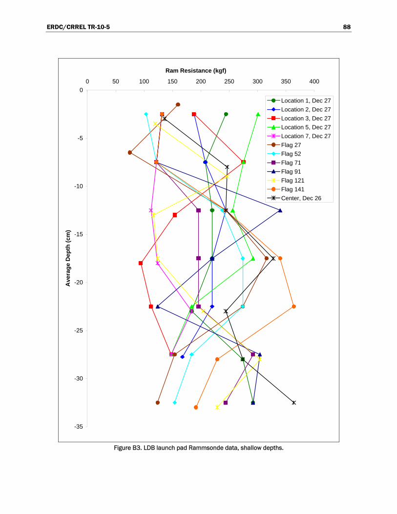
ERDC/CRREL TR-10-5 88
-35
-30
-25
-20
-15
-10
-5
0
0 50 100 150 200 250 300 350 400
Ram Resistance (kgf)A
vera
ge
Dep
th (
cm)
Location 1, Dec 27
Location 2, Dec 27
Location 3, Dec 27
Location 5, Dec 27
Location 7, Dec 27
Flag 27
Flag 52
Flag 71
Flag 91
Flag 121
Flag 141
Center, Dec 26
Figure B3. LDB launch pad Rammsonde data, shallow depths.

ERDC/CRREL TR-10-5 89
-120
-100
-80
-60
-40
-20
0
0 500 1,000 1,500 2,000 2,500
Ram Resistance (kgf)A
vera
ge
Dep
th (
cm)
22-Dec (1)
23-Dec, Left
23-Dec, Right
22-Dec
25-Dec
Series5
26-Dec
Series9
27-Dec
28-Dec
30-Dec
Figure B4. Strength profiles changes over time on Williams Field Road, MP4.

ERDC/CRREL TR-10-5 90
-30
-25
-20
-15
-10
-5
0
0 200 400 600 800 1,000 1,200 1,400 1,600 1,800 2,000
Ram Resistance (kgf)A
vera
ge
Dep
th (
cm)
Black Island Lane, Transition
Black Island Lane, Curve
Black Island Lane, MP2
Black Island Lane, MP3
Black Island Lane, MP4
Center Lane, Transition
Erebus Lane, Transition
Erebus Lane, Curve
Erebus Lane, MP2
Erebus Lane, MP3
Erebus Lane, MP4
Track Lane, Transition
Track Lane, Transition2
Track Lane, Curve
Track Lane, MP2
Track Lane, MP3
Track Lane, MP4
Figure B5. Compilation of Williams Field Road near surface strength profiles on all lanes and
along the length of the road (30 Dec 2002).

ERDC/CRREL TR-10-5 91
-30
-25
-20
-15
-10
-5
0
0 200 400 600 800 1,000 1,200 1,400 1,600 1,800 2,000
Ram Resistance (kgf)A
vera
ge
Dep
th (
cm)
Black Island Lane, Transition
Black Island Lane, MP2
Black Island Lane, MP3
Black Island Lane, MP4
Center, Transition
Erebus Lane, Transition
Track Lane, Transition
Track Lane, Transition2
Figure B6. Comparison of roadway and transition area strength profiles on Williams Field
Road (30 Dec 2002).

ERDC/CRREL TR-10-5 92
-45
-40
-35
-30
-25
-20
-15
-10
-5
0
0 100 200 300 400 500 600 700
Ram Resistance (kgf)A
vera
ge
Dep
th (
cm)
Test B
Test C
Test D
Test E
Test F
Test A
Figure B7. Study in variability in strength profiles taken in the same vicinity on the same day
(Williams Field Road MP2, Black Island Lane CL, 26 Dec 2002).

ERDC/CRREL TR-10-5 93
-70
-60
-50
-40
-30
-20
-10
0
0 100 200 300 400 500 600 700 800 900 1,000
Ram Resistance (kgf)A
vera
ge
Dep
th (
cm)
Erebus Lane, before Delta, 2 Jan 2003
Erebus Lane, after Delta, 2 Jan 2003
Erebus Lane, after Delta, 3 Jan 2003
Figure B8. Strength profiles on Pegasus Road before and after Delta packing.

ERDC/CRREL TR-10-5 94
Appendix C: Clegg Measurements Table C1: CIH Measurements
Date Location
Reading Number Calculated
1 2 3 4 5 CBR Ram (kgf)
E (Mpa)
27-Dec-02 LDB Launch Pad Inner Circle
Loc 1 9 9 7 7 nr 7.2 28 4.3
Loc 1 nr nr 6 7 7 6.8 25 3.9
Loc 2 5 5 5 10 11 9.5 51 6.6
Loc 3 4 7 7 9 9 9.0 46 6.1
Loc 4 4 nr 8 11 12 12.1 84 9.4
Loc 4 4 4 4 8 9 7.2 28 4.3
Loc 5 8 9 9 8 9 9.5 51 6.6
Loc 7 nr nr nr 8 11 10.8 66 7.9
Loc 7 nr nr 6 6 9 7.2 28 4.3
27-Dec-02 Williams Road Track Lane
MP2 10 12 13 14 13 17.6 185 15.6
MP2 15 14 15 13 15 19.7 233 18.1
28-Dec-02 Williams Field Apron
nr 11 11 13 13 15.7 145 13.4
nr 6 9 11 12 12.7 93 10.0
nr 8 9 12 10 12.1 84 9.4
nr 9 11 12 14 15.7 145 13.4
28-Dec-02 Williams Road Black Island Lane
MP2 nr 7 10 10 11 12.1 84 9.4
MP2 5 10 11 13 13 15.7 145 13.4
MP2 nr nr 6 7 8 7.2 28 4.3
MP2 6 8 10 11 11 12.7 93 10.0
30-Dec-02 Williams Road Black Island Lane
Curve nr nr 6 6 7 6.4 22 3.5
Curve nr 5 5 8 8 7.2 28 4.3
Curve 5 5 10 12 13 14.4 122 12.0
MP3 nr nr 6 nr 7 6.6 24 3.7
MP3 4 6 7 9 8 8.5 41 5.6
30-Dec-03 Williams Road Erebus Lane
MP3 nr 5 7 8 nr 7.8 34 5.0
MP3 4 6 8 9 nr 9.2 48 6.4
MP3 nr nr 7 9.0 10.0 9.5 51 6.6
Track Lane MP2 nr nr 11 13 13 15.7 145 13.4
MP4 nr nr nr 9 10 10.8 66 7.9
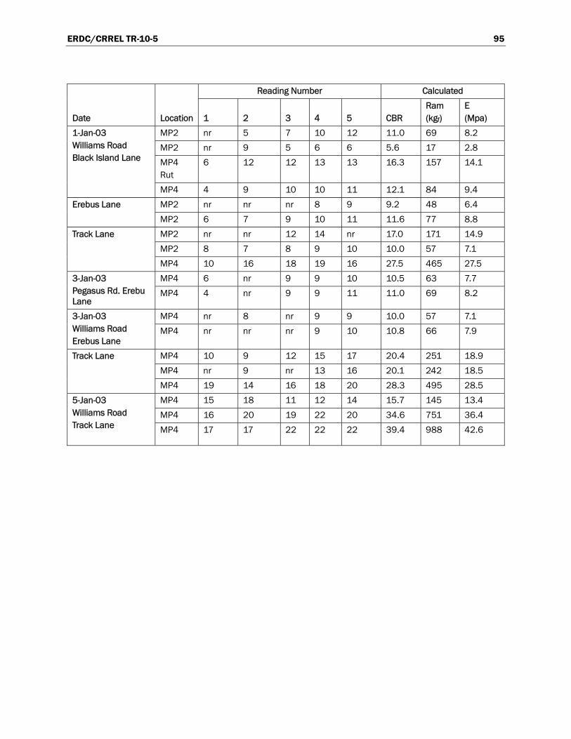
ERDC/CRREL TR-10-5 95
Date Location
Reading Number Calculated
1 2 3 4 5 CBR Ram (kgf)
E (Mpa)
1-Jan-03 Williams Road Black Island Lane
MP2 nr 5 7 10 12 11.0 69 8.2
MP2 nr 9 5 6 6 5.6 17 2.8
MP4 Rut
6 12 12 13 13 16.3 157 14.1
MP4 4 9 10 10 11 12.1 84 9.4
Erebus Lane MP2 nr nr nr 8 9 9.2 48 6.4
MP2 6 7 9 10 11 11.6 77 8.8
Track Lane MP2 nr nr 12 14 nr 17.0 171 14.9
MP2 8 7 8 9 10 10.0 57 7.1
MP4 10 16 18 19 16 27.5 465 27.5
3-Jan-03 Pegasus Rd. Erebu Lane
MP4 6 nr 9 9 10 10.5 63 7.7
MP4 4 nr 9 9 11 11.0 69 8.2
3-Jan-03 Williams Road Erebus Lane
MP4 nr 8 nr 9 9 10.0 57 7.1
MP4 nr nr nr 9 10 10.8 66 7.9
Track Lane MP4 10 9 12 15 17 20.4 251 18.9
MP4 nr 9 nr 13 16 20.1 242 18.5
MP4 19 14 16 18 20 28.3 495 28.5
5-Jan-03 Williams Road Track Lane
MP4 15 18 11 12 14 15.7 145 13.4
MP4 16 20 19 22 20 34.6 751 36.4
MP4 17 17 22 22 22 39.4 988 42.6

ERDC/CRREL TR-10-5 96
Appendix D: Snow Moisture Measurements Table D1: Snow moisture measurement on McMurdo snow roads, 2003.
Date, Location Moisture meter reading
Associated snow density (kg/m3)
Liquid Water %
2 Jan 2003 on Pegasus Road
Air 110
Delta Tracks 1/2 plane 125 556 0.63
Windblown drift 1/2 plane 118 370 0.95
Windblown drift full plane 114 370 3.63
3 Jan 2003 on Pegasus Road
Air 107
Goosetrack 1/2 plane 121 472 0.22
Goosetrack 1/2 plane 124 472 1.29
3 Jan 2003 on Williams Field Road
Air 107
Snow road bed, 1/2 plane 115 500 2.61

ERDC/CRREL TR-10-5 97
Appendix E: Vehicle Information and Tire Pressure Measurements
Table E1: Vehicle information and tire pressure measurements.
Tire Pressure Tandem (front)
Vehicle # Type GVW (lbs) Tire Size Tire Type
LF (psi)
RF (psi) LR (psi)
RR (psi)
L (psi) R
VA00206 E-350 Pass Van 9300 17/40-16.5LT Dick Cepek, Fun Country 6 ply/LRC 21 18 20 29
VA00204 E-350 Pass Van 9300 17/40-16.5LT Dick Cepek, Fun Country 6 ply/LRC 30 31 28 27
VA00213 E-350 Pass Van 9300 17/40-16.5LT Dick Cepek, Fun Country 6 ply/LRC 32 33 28 22
93-26097 E-350 Airporter 11500 17/40-16.5LT Dick Cepek, Fun Country 6 ply/LRC 38 37 32 34
93-26095 E-350 Airporter 11500 17/40-16.5LT Dick Cepek, Fun Country 6 ply/LRC 28 29 27 30
94-13649 Delta (Flipper) 66 X 44.00-25NHS 6 ply Goodyear Tundra Grip Terra Tire 25 20 13 18 10 19
TL00125 F350 LT315/75R16 Wild Spirit M&S 50 psi cold 121Q 21 54 50 54
TL00119 F350 36 X 14.5 16.5LT Micky Thompson Baja Belted M&S 30 psi 31 30 31 30
VA00219 E250 Ford 17/40-16.5LT Dick Cepek Fun Country Max 60 psi 23 29 25 30
VA00207 E350XL Ford 9300 17/40-16.5LT Dick Cepek Fun Country Max 60 psi 30 29 8 28
VA00216 E350XL Ford Super Duty 17/40-16.5LT
Dick Cepek Fun Country Max 60 psi-Cracking & looks new 23 26
27 cracked 20
VA00218 E350XL Ford Super Duty 9300 17/40-16.5LT Dick Cepek Fun Country 20 21 21 18
VA00210 E350XL Ford Super Duty 9300 17/40-16.5LT
Dick Cepek Fun Country Max 60 psi 20 20 19 21
95-05363 Delta (Gale) 42000 66 X 44.00-25NHS Goodyear Terra Tire Tundra Grip 12 22 19 16
96-41045 Tera Bus (Ivan) 67000 66 X 44.00-25NHS
Goodyear Terra Tire Tundra Grip 16 ply radius 40 psi max 25 24 25 25 20 24
TL00128 F350 36 X 14.50 X 16.5 Mickey Thompson 28 25 28 30
VA00209 E350 Van 9300 17/40-16.5 Dick Cepek 22 23 23 23
15092 Foremost Delta III (Brenda) 63000 66 X 44.00-25 M&S Goodyear Tundra Grip Terra Tire 20 18 24 17 21 20
94-13649 Foremost Delta III (Flipper) 58300 66 X 44.00-25 M&S
Goodyear Tundra Grip Terra Tire Grip, 6 ply 15 18 7 12 5 18

REPORT DOCUMENTATION PAGE Form Approved
OMB No. 0704-0188 Public reporting burden for this collection of information is estimated to average 1 hour per response, including the time for reviewing instructions, searching existing data sources, gathering and maintaining the data needed, and completing and reviewing this collection of information. Send comments regarding this burden estimate or any other aspect of this collection of information, including suggestions for reducing this burden to Department of Defense, Washington Headquarters Services, Directorate for Information Operations and Reports (0704-0188), 1215 Jefferson Davis Highway, Suite 1204, Arlington, VA 22202-4302. Respondents should be aware that notwithstanding any other provision of law, no person shall be subject to any penalty for failing to comply with a collection of information if it does not display a currently valid OMB control number. PLEASE DO NOT RETURN YOUR FORM TO THE ABOVE ADDRESS.
1. REPORT DATE (DD-MM-YYYY) May 2010
2. REPORT TYPE Final Report
3. DATES COVERED (From - To)
4. TITLE AND SUBTITLE
Snow Roads at McMurdo Station, Antarctica
5a. CONTRACT NUMBER
5b. GRANT NUMBER
5c. PROGRAM ELEMENT NUMBER
6. AUTHOR(S)
Sally A. Shoop, Gary Phetteplace, and Wendy L. Wieder
5d. PROJECT NUMBER
5e. TASK NUMBER
5f. WORK UNIT NUMBER
7. PERFORMING ORGANIZATION NAME(S) AND ADDRESS(ES) 8. PERFORMING ORGANIZATION REPORT NUMBER
See reverse. ERDC/CRREL TR-10-5
9. SPONSORING / MONITORING AGENCY NAME(S) AND ADDRESS(ES) 10. SPONSOR/MONITOR’S ACRONYM(S)
National Science Foundation Office of Polar Programs 4201 Wilson Boulevard Arlington, VA 22230
11. SPONSOR/MONITOR’S REPORT NUMBER(S)
12. DISTRIBUTION / AVAILABILITY STATEMENT Approved for public release; distribution is unlimited.
13. SUPPLEMENTARY NOTES
14. ABSTRACT
Snow roads are the critical link between McMurdo Station and its snow and ice airfields. During warmer periods of the Antarctic summer, these roads can deteriorate significantly, requiring supplies and personnel to be transported by specialized limited-supply vehicles. Less severe failures restrict traffic to the slow tracked-vehicle fleet. The Antarctic snow roads were observed during the 2002-2003 season to gain a better understanding of their behavior and to identify potential performance improvements that could be made. Our objectives were; to explore ways to reduce the incidence of snow road failures, to understand and document current construction and maintenance procedures, and to suggest processes to optimize labor and equipment use. We monitored the snow conditions, compared strength measurements with processing techniques, monitored strength setup with time (sintering), monitored snow road temperature profiles, observed any road failures, and collected fleet data (use, vehicles, tire pressures, speeds). Our observations during the 2002 and 2003 austral summer are reported along with a substantial summary of historic snow road observations and guidance. The results of this project are timely in light of a current transportation study to consolidate to a single McMurdo airfield where the research and development to achieve a robust and resilient snow road network will be crucial for airfield operability.
15. SUBJECT TERMS
McMurdo station Rammsonde strength values
Sintering Snow road failure Snow roads
Snow road technology
16. SECURITY CLASSIFICATION OF: 17. LIMITATION OF ABSTRACT
18. NUMBER OF PAGES
19a. NAME OF RESPONSIBLE PERSON:
a. REPORT
UNCLASSIFIED
b. ABSTRACT
UNCLASSIFIED
c. THIS PAGE
UNCLASSIFIED 116 19b. TELEPHONE NUMBER (include area code)
Standard Form 298 (Rev. 8-98)Prescribed by ANSI Std. 239.18

7. PERFORMING ORGANIZATION NAME(S) AND ADDRESS(ES) (Concluded)U.S. Army Engineer Research and Development Center Cold Regions Research and Engineering Laboratory 72 Lyme Road Hanover, NH 03755-1290;
GWA Research LLC 7 Masa Morey Lane Lyme, NH 03768;
Science and Technology Corporation 10 Basil Sawyer Drive Hampton, VA 23666-1395