snaplock fiber reinforced composites technology applied to
TRANSCRIPT

Division of Research & Innovation
Snaplock Fiber Reinforced Composites Technology Applied to Overhead Sign Structures Design, Construct, and Test a Fiber Reinforced Composite Overhead Sign Truss
Final Report
Report CA07-0246 December 2008

Snaplock Fiber Reinforced Composites Technology Applied to Overhead Sign Structures
Design, Construct, and Test a Fiber Reinforced Composite Overhead Sign Truss
Final Report
Report No. CA07-0246
December 2008
Prepared By:
Composite Support & Solutions Inc. 767 Channel Street
San Pedro, CA 90731
Prepared For:
California Department of Transportation Engineering Services Center
1801 30th Street Sacramento, CA 95816
California Department of Transportation Division of Research and Innovation, MS-83
1227 O Street Sacramento, CA 95814

DISCLAIMER STATEMENT
This document is disseminated in the interest of information exchange. The contents of this report reflect the views of the authors who are responsible for the facts and accuracy of the data presented herein. The contents do not necessarily reflect the official views or policies of the State of California or the Federal Highway Administration. This publication does not constitute a standard, specification or regulation. This report does not constitute an endorsement by the Department of any product described herein.

STATE OF CALIFORNIA DEPARTMENT OF TRANSPORTATION TECHNICAL REPORT DOCUMENTATION PAGE TR0003 (REV. 10/98)
1. REPORT NUMBER
CA07-0246
2. GOVERNMENT ASSOCIATION NUMBER 3. RECIPIENT’S CATALOG NUMBER
4. TITLE AND SUBTITLE Snaplock Fiber Reinforced Composites Technology A pplied to Overhead Signs: Design, Construct, and Test a Fiber Reinforced Composite Overhead Sign Truss
5. REPORT DATE
December, 2008 6. PERFORMING ORGANIZATION CODE
7. AUTHOR(S)
Clem Hiel
8. PERFORMING ORGANIZATION REPORT NO.
9. PERFORMING ORGANIZATION NAME AND ADDRESS
Composite Support & Solutions Inc 727 Channel Street San Pedro, CA 90731
10. WORK UNIT NUMBER
11. CONTRACT OR GRANT NUMBER
DRI Research Task No. 0246 Contract No. 59A0343
12. SPONSORING AGENCY AND ADDRESS
California Department of Transportation Engineering Services Center 1801 30th Street Sacramento, CA 95816
California Department of Transportation Division of Research and Innovation, MS-83 1227 O Street Sacramento, CA 95814
13. TYPE OF REPORT AND PERIOD COVERED
Final Report
14. SPONSORING AGENCY CODE
913
15. SUPPLEMENTAL NOTES
.
16. ABSTRACT
This report paper summarizes progress on a research program to investigate the use of composite materials for overhead sign bridges, as well as the assembly of these structures without fasteners. A composite overhead sign bridge was designed and analyzed. The traditional profile shapes, which are in use for steel sign bridges, were not
copied in composite materials. Instead two types “lineals” with a special rectangular cross sections for functionality were designed. The cross-sectional shape and fiber architecture of these tubes is dominated by the requirement for a “snap-fit” assembly. The complexities in geometry and fiber architecture can easily be handled by an automated “Pultrusion” process. Since Pultrusion-dies are expensive the “lineals” were first manufactured by hand lay-up, and resin infusion on wood tooling. The snap-fit joint
created by both parts was subsequently assembled and tested in order to provide a proof of concept without expensive Pultrusion-dies or the added cost of die modifications. As a next step the most extensively loaded joint area in the sign bridge structure was assembled from the two Pultruded tubular sections and
subject to the loads which were derived from the analysis. As such the load factors and failure modes have been established. This report outlines a research program undertaken at CSSI to investigate the feasibility of a sign structure which can be erected quickly. The
feasibility of a fastenerless 90-ft sign truss in composite materials has been investigated. A two post sign truss with a clear span of 90 feet was selected as a benchmark. The layout of a fastenerless composite sign truss with two posts
revealed significant weight savings. A newly developed composite “snap joint” which is pultrudable is the heart of this lightweight sign structure. Performance tests revealed that this joint has a static load capacity of more than 22,000 lbs.
17. KEY WORDS
Composite materials, overhead sign truss, snap-fit assembly, feasibility, design, construction, analysis, testing
18. DISTRIBUTION STATEMENT
No restrictions. This document is available to the public through the National Technical Information Service, Springfield, VA 22161
19. SECURITY CLASSIFICATION (of this report)
Unclassified
20. NUMBER OF PAGES
95 Pages
21. PRICE
Reproduction of completed page authorized

FINAL REPORT
DESIGN, CONSTRUCT, AND TEST A FIBER REINFORCED COMPOSITE OVERHEAD SIGN TRUSS
CONTRACT 59A0343
Dr. Clem Hiel Composite Support & Solutions Inc, San Pedro, CA.
767 Channel Street San Pedro, CA 90731
ABSTRACT: This report paper summarizes progress on a research program to investigate the use of composite materials for overhead sign bridges, as well as the assembly of these structures without fasteners.
A composite overhead sign bridge was designed and analyzed. The traditional profile shapes, which are in use for steel sign bridges, were not copied in composite materials. Instead two types “lineals” with a special rectangular cross sections for functionality were designed. The cross-sectional shape and fiber architecture of these tubes is dominated by the requirement for a “snap-fit” assembly. The complexities in geometry and fiber architecture can easily be handled by an automated “Pultrusion” process.
Since Pultrusion-dies are expensive the “lineals” were first manufactured by hand lay-up, and resin infusion on wood tooling. The snap-fit joint created by both parts was subsequently assembled and tested in order to provide a proof of concept without expensive Pultrusion-dies or the added cost of die modifications.
As a next step the most extensively loaded joint area in the sign bridge structure was assembled from the two Pultruded tubular sections and subject to the loads which were derived from the analysis. As such the load factors and failure modes have been established.
This report outlines a research program undertaken at CSSI to investigate the feasibility of a sign structure which can be erected quickly. The feasibility of a fastenerless 90 sign truss in composite materials has been investigated.
A two post sign truss with a clear span of 90 feet was selected as a benchmark. The layout of a fastenerless composite sign truss with two posts revealed significant weight savings. A newly developed composite “snap joint” which is pultrudable is the heart of this lightweight sign structure. Performance tests revealed that this joint has a static load capacity of more than 22,000 lbs.
1

The report consists of eight sections.
The introduction summarizes our findings about the use of composite materials in overhead sign structures throughout the world.
Section 2 provides the basic information on a benchmark overhead sign truss and discusses four concepts which were considered for a composite overhead sign bridge
Section 3 summarizes the material system identification
Section 4 provides details of the pultrusion manufacturing process including the fiber dispensing system, and the fiber impregnation system and sequence.
Section 4 provides information about quality control, including a trial assembly of a 30 ft section of the overhead sign bridge design.
Section 5 gives the analytical and test results. Part of this section is dedicated to a critical review of the snap joint design, its failure modes, and possible ways to improve the design. Also provided is a full structural analysis of a benchmark composite overhead sign truss for the load cases which are identified by AASHTO
Section 7 gives the summary and the conclusions for this project.
2

REPORT OUTLINE:
1. Introduction
2. Design Methods
3. Material System Identification
4. Manufacturing Process
5. Quality Control Procedures
6. Analytical and Test Results
7. Conclusions and Recommendations
8. References
3

1. INTRODUCTION The application of composite materials has been pursued technically and commercially in a variety of structural engineering applications. These applications cover a very wide range from power delivery infrastructure and bridge decks to maritime docking structures. One documented case [1] explores the possibility of temporary composite structures within the British Rail network. It concerns temporary structures which assist in revenue earning after disruptions by supporting overhead electrification conductors and associated equipment and temporary footbridges to provide across track access without disruption of service.
On 28 November 1995, a CMS structure located on Interstate I-15 in San Bernardino County, California, failed. As a result more than 200 CMS structures throughout the state of California were inspected to determine the extent of wind-induced cracking in their welded components. Cracked welds were found in the post-to-base plate connections and in the arm-to-post welded connections.
Many of the Nation’s DOT’s have documented cases [2, 3] of sign-truss structures and signal mast arms made of steel and aluminum which have experienced fatigue-failures in the welds. In a number of cases composite materials have been used for the repairs [4]. Other recommendations for increased reliability range from insuring weld quality to dampers on the mast arms.
4

Figure 1 Use of Composite Materials to Repair Overhead Sign Structures
Figure 2 illustrates some of the weld fatigue problems experienced by NYDOT for aluminum sign bridges.
5

Figure 2 Weld Fatigue Failure in Aluminum Sign Bridge as Experienced by NYDOT.
These sign bridges have been repaired with FRP wraps, which functioned as crack arrestors, when bonded over the failed area.
The U.K. Highways Agency has been a leader in efforts to use composite materials for sign structures as illustrated in Figure 3.
Figure 3 Overhead Sign Structures in the U.K.
As mentioned in the article, sign structures are technologically possible, but the main barrier is cost. The U.K. effort evidently uses sandwich panel construction in conjunction with resin transfer molding (RTM). As such the overhead sign structure manifests itself as a composite boxbeam, which is not the most economic and lightest construction, especially not for the longer overhead sign structures.
Figure 4 illustrates another example of an overhead sign structure, also from the U.K, of a prototype structure on Motorway M25.
6

Figure 4 Composite Variable Message Sign Structure with Steel Post on the M25 Motorway in UK
This cantilever type is used as a variable message sign and is attached to a steel post. It’s actual detail construction is unknown, but it is reasonable to assume that it is also an RTM type sandwich construction.
To the best of our knowledge, the examples shown in Figures 3 and 4 represent the state of the art in overhead sign structures.
In this report we have opted for an entirely different approach, which is to rely on automated pultrusion technology to manufacture truss elements which can easily be assembled into sign structures. This approach not only creates a light structure, but also makes it cost competitive with metal structures technology.
Additionally, composite materials are a natural for sign truss applications because of their inherent favorable fatigue characteristics, high damping, the fact that they don’t corrode and thus for their inherent low maintenance potential. Composite sign structures have a substantially lower weight and can thus be installed with lighter equipment. Additionally the recent increases in the cost of energy, making steel, concrete, and transportation costs favor alternative solutions in the form of lightweight composite structures.
The research currently pursued by CSSI ads a novel element, which is the use of high performance structural snap joints. The state of the art has been discussed in a 1997 conference paper by Goldsworthy and Hiel [5]. These joints do not only provide for rapid
7

on-site assembly, but they also have shown the promise of substantial contributions to the structural damping capacity of the structure. In an era where a twenty minute tie-up wastes over 2000 vehicle hours, causes a 3 mile backup and takes 2.5 hours to clear the world is moving towards IVHS (Intelligent Vehicle Highway System) [6] for which the “stealth” like qualities of fastenerless composites truss structures are an asset.
The section below illustrates the various design concepts which were developed during this project.
8

2. DESIGN METHODS/ CONCEPTS In the United States, sign, signal and light support structures are designed using the AASHTO standard specifications for structural supports for highway signs, luminaires and traffic signals [7]
The benchmark steel sign truss for this research is a 90 feet structure with two posts as reproduced from drawing S5 in the Caltrans Standard Plans [8] below.
Figure 5 Benchmark Steel Sign Truss From Caltrans Standard Plans [8]
The estimate for the weight of a sign truss with a 90 foot clear span is given in Table-I below.
Table I Weight Estimate of Steel Sign Truss
9

Various approaches have been used towards the conceptual design of the overhead sign structure as discussed below:
1.1 Concept #1 Pultruded beam and corner elements
The Overhead Sign-Truss is conceptualized as truss members, shown in Figure 6, which can easily be assembled together with an interlocking type mechanism without the use of
mechanical fasteners or adhesives.
Figure 6 Concept for Sign Structure new Corner Joint
Figure 7 shows a pultruded connection detail that has sufficient flexibility to snap-fit into the pultruded corner elements.
Figure 7 Pultruded Connection Detail
Figure 8 shows a slight deviation of this concept with more complicated corner joints.
10

Figure 8 Other Concept for Sign Bridge Corner Joint
The second concept emphasizes the pultrusion of 6 to 8 ft wide sandwich panels or ribbed hollow panels. These panels are then cut along certain angles to provide the truss members which are needed for the fastenerless assembly of an overhead sign structure.
1.2 Concept # 2
Figure 9 is entirely novel and virtually eliminates the machining which was an integral part of the first generation snaplock joints which were discussed in the background section above.
11

Figure 9 Pultruded Panel
The angled cross-members utilized for assembly and shown in detail in Figure 10 can be obtained by cutting a wider panel at the appropriate angle. This approach as visualized in
Figure 10 Angled cross-members and novel idea for pultrusion without the need for NC-machining
A key element of this task is the design of the fiber architecture which needs to be defined early on. A folded fiber architecture not only allows the joint to be functional but also introduces adequate interlaminar tension and shear resistance which translates into good durability. This is an example of our approach to designing durability into a structure by making vital load paths fiber dominated.
12

Another concept that was pursued was that of an “Isotruss” structure.
1.3 Concept # 3
Figure 11 shows an “Isotruss” structure which was assembled by snap-joining of tubular elements.
Figure 11 Isotruss Structure
This type of structure derives its stiffness from its geometry, much in the same sense as the geodetic structures which were designed by Buckminster Fuller.
Figure 12 shows concepts of the various joint configurations which would allow for snap fit assembly of these tubular structures.
13

Figure 12 Joint Configurations for Assembly of Tubular Structures
Figures 13, and 14 shows the actual assembly sequence of a complicated truss joint.
14

Figure 13 Joint Halves
Figure 14 Joint halves Assembled
15

The concept that is discussed below is a more traditional snap-joint with a pultrusion that can accept cross-members in orthogonal directions.
Concept # 4
Figure 15 illustrates detail of two perpendicular cross members entering the longitudinal beam.
Figure 15 Orthogonal Cross Member Entrance
Because this concept showed a lot of promise, we decided to prove its manufacturability by resin infusion. Figure 16(a, b) shows the snap joint which was made in this way. The reason for using resin infusion was that this is the cheapest way to create a hardware model of the concept. We did however respect at all times the fiber architecture in such a way that the part could later be manufactured by pultrusion.
16

Figure 16 a, b Snap-joint infusion and finished snap joint assembly
Figure 16a illustrates the infusion setup. The operator is using an ultrasonic leak detector to eliminate vacuum leaks at the edges of the vacuum bag and at the fittings.
Figure 16b shows the finished snap-joint. Because of the merit of this joint configuration, it was decided to select this concept for implementation.
The fastenerless (snap joint) composite configuration is reproduced in Figure 17.
Figure 17 Benchmark Composite Sign Truss
17

The detail inset in Figure 17 shows the fastenerless joint (snap joint) configuration. The two cross-members (bleu) snap into what is essentially a boxbeam (yellow) with two entirely separated cavities.
The weight estimate of the composite sign truss is given in Table-II
Table II Weight Estimate of Composite Sign Truss
The total weight comes out to 3515 lbs which is less than 1/3th of the weight of the benchmark steel sign truss.
18

3. MATERIAL SYSTEM IDENTIFICATION The material system consists of E glass fiber and Vinylester resin.
The E-glass has the multipurpose sizing which is compatible with vinylester resin.
The vinylester resin has been formulated as shown in the table below.
Table III Resin Formulation
The fiber layup schedules are provided in the drawing package that is attached as an appendix.
The structural properties of the pultruded sections were determined as:
EL = 3.5 Msi (ASTM C1557 ) GLT = 0.425 Msi (ASTM D4475) Poisson Ratio: 0.33 (ASTM C1577)
These values a higher than for traditional, non-structural pultrusions which typically have an E modulus of 2.6 Msi.
19

Fiber volume fractions have been determined on the basis of weight measurements, and they are well over 50% for all samples tested.
20

4. MANUFACTURING PROCESS Pultrusion is a continuous fabrication method, and as such it has become a preferred manufacturing method for most of the composite structures which have been pursued commercially in structural engineering. Our company (CSSI) owns two industrial capacity pultrusion machines dedicated to pultrude the hardware for extended test configurations and for full size sign trusses.
The components of the sign truss have been designed so that they can be fabricated by the pultrusion process that is schematically shown in Figure 18.
Figure 18 Fabrication of Sign Truss Elements by Pultrusion Process
Figure 19 shows a drawing of the fiber dispensing system.
Figure 19 Fiber Dispensing System
This combination of fiber delivery towards the pultrusion-die and impregnation with resin in the process is the heart of the pultrusion operation.
21

Figure 20-22 show actual images of the pultrusion setup
Figure 20 Global view of the Pultrusion Setup
Figure 21 Detail of fiber Dispensing
22

Figure 22 Pultruded Component Exciting the Die
Figure 23 shows the pultruded elements which are stored for further machining and finishing operations
Figure 23 Finished Pultrusions
23

5. QUALITY CONTROL PROCEDURES The quality control and storage of resins and fibers was conducted according to ASTM requirements.
The proper design of the fiber dispensing system is key to the quality of the pultruded components.
Figure 24 shows the section of a pultruded cross-member.
Figure 24 Section of Pultruded Cross-Member
24

These sections were examined for fiber density, and fiber distribution. Cuts were made every 60 ft and examined. No process variables were changed between cuts in order to assure the consistency of the pultruded component.
An important element in the determination of quality was in the ability to assemble the truss structure.
Figure 25 Assembled Overhead Sign Structure
25

Figure 26 Assembled Overhead Sign Structure
Figure 27 Detail Joint of Assembled Overhead Sign Structure
The connection of the truss to the vertical pole is shown in Figure 28
26

Figure 28 Connection of Truss to Vertical Pole
27

6. ANALYTICAL AND TEST RESULTS Structural “snap-fits” for composite materials are a path-breaking approach for composite structures assembly which is capable of revitalizing some key opportunities for the U.S. industry and to define the tools, techniques, and ideas that can help put our efforts on a broad science and engineering footing.
Figure 29 illustrates our concept of creating a structural connection between two profiles without the need for fasteners.
Figure 29 Snap Fit for Creating a Structural Connection
The yellow and the red profile are preferably fabricated by pultrusion, although we have used resin infusion for samples and small series as well. The methodology could be used with any of the composites manufacturing methods because snap-fit technology is merely a way of thinking about assembly and not tied to any particular method of manufacturing.
As a demonstration of the path-breaking potential of snap-fits we assembled the 9.14 meter (30 ft) truss structure shown in Figure 30 only 15 minutes.
Figure 30 Trial assembly of Snap-fit Truss Structure for this Project
28

The assembly sequence and steps have been documented in a separate internal report [9], which will be the basis for a future paper in a refereed Journal on composite materials technology.
The assembly in Figure 30 illustrates the ultimate goal for which we are developing this very cost competitive new assembly technology. The entire structure took only 15 minutes to assemble versus an estimated 2 hours for an equivalent metal structure. This result shows the practicality and the applicability of this approach and the opportunities which it embodies for further research and commercial application. By developing snap-fit technology for composite materials, we enable U.S. industry to remove the most formidable barrier that they are facing. This barrier is cost! Composite materials are always more expensive than traditional materials. Purchased cost or installed cost almost always favors the status quo. The U.S. industry is shoveling water upstream when it tries to overcome this barrier head-on or when they ask their customers to modify their perceptions and practices, or ask their customers to embrace “life-cycle” costing.
Figure 31 shows the snap fit connection which was shown above in Figure 30 as it is being loaded in a test frame. For reference we call this the benchmark snap-fit.
(a) (b)
29

(c) (d)
Figure 31 Benchmark Snap-Fit loaded in the Testing Machine
The load carrying capacity of the benchmark snap-fit is in the 104,540 N (23,000 lbs) range. We notice only a slight non-linearity prior to reaching the maximum load. This means that there are few non-linear phenomena acting. The snap-fit continues to carry a significant load once it has passed the maximum load point. This is shown further in results shown in Figure 37.
Figure 3d shows the setup of the snap-fit for compression loading. It was observed that the compression strength was on average 15% higher for all observed load cases.
SNAP-FIT FAILURE MODES
We did examine the failure mode of our benchmark snap-fit. Figure 32 shows the cracked component, after the joints was taken apart. It points to visible and stable cracking caused by a stress concentration at the radiussed corner of the opening in the double boxbeam part. This stress concentration could be alleviated in a number of ways
Figure 32 Critical Review of failure mode(s)
30

We notice that cracking has initiated at the corners and has then spread in the lengthwise direction of the part. This is explained by the stress concentration created by the small radius in the rectangular window opening. The corner had only a slight radius of 1/8”. This radius gives us a stress concentration of a magnitude which was determined both theoretically and experimentally.
Residual stresses may be a factor, since the corner of the larger profile is participating in the load transfer as shown in Figure 33
Figure 33 Contact surfaces
This could be determined by using a low shrink resin such as epoxy instead of the currently used vinylester.
Figure 34 shows the actual drawing of the fiber architecture. The table details the stitched fabric, the unidirectional fiber and the continuous strand mat. The resin was an Ashland Momentum vinylester resin. The orthotropic stiffness and the volume fraction were determined on the basis of this information.
31

Figure 34 Fiber architecture
It was determined that this part has a 64% volume fraction of fibers by volume.
An examination of literature sources [10, 11] related to corner stress concentrations of plates with a square hole in bending has produced figures 35 a, b.
Figure 35 a, b Stress Concentration around a Square Hole in Bending
A stress concentration factor of 2.38 has been reported at the sharp corner.
32

A critical examination of the other component (the insert) revealed that there was no damage or cracking. This is due to the folded fiber architecture which we devised for this component. So far we have never been able to fail this component. It will be proposed to do this in our initial Phase-II effort, but this component does not appear to be a limiting factor.
STRESS/ STRAIN OBSERVATION METHOD TO OBSERVE THE SNAP-ENGAGEMENT AREA
Our company has direct working experience and operating knowledge with photoelastic coatings (photostress), moiré-Interferometry, and speckle-Interferometry. Based on the critical review of the failure modes in task 1, and based on communications with industry experts, we selected the photostress method [12, 13] for further examination of the areas of interest.
The Photostress method was invented by Dr. Felix Zandman [14]. It consists of bonding a transparent photoelastically sensitive plastic to the composite as shown in Figure 8. When putting the composite under stress, the stress equally affects the plastic. The plastic stretches in the same way as the composite it is bonded to. Its surface assumes the same deformations as the surface of the composite. The plastic has become a sensor for changes in the composite surface. Instead of speculating on equivalencies as is done in traditional transmission photoelasticity, this technique allows us to look at, and investigate the real thing.
Figure 36 Photostress method Applied to Composite Snap-Fit
The area of interest is the rectangular window with the rounded corners, which is the failure area as we discussed above.
The photoelastically sensitive plastic sheets were first calibrated in bending. The objective was to determine the fringe constant. The obtained value was 23 Mpa/ fringe. The detailed procedure has been outlined in a separate internal report [15].
33

Although the photoelastic method had fallen back with the emergence of FE (finite element) methods, it has made a come-back as is illustrated in ref’s [16-18] which date from 2003 and 2006 and which investigate stress reduction and fatigue sensitivity in traditional bolts.
THREE DIMENSIONAL FINITE ELEMENT MODEL FOR BENCHMARK SNAP FIT SIMULATION AND IMPROVEMENT
Figure 37 shows the three dimensional model that was used for finite element implementation.
Figure 37 Three dimensional Snap-Fit FE-model
The CAD-file was transferred to Patran [19], which was used to mesh the geometry. The FE analysis was performed with NASTRAN. We performed a linear stress analysis, as shown in Figure 38, and assumed a uniformly distributed engagement load distribution applied by the insert.
34

Figure 38 Typical Stress Distribution at the corners of the Window Section
The obtained stress distribution clearly puts most of the load into the engagement area around the window. The second, and lower, engagement protrusion is lighter loaded. An increase in the stiffness of the load path that engages this lower protrusion would help to equalize the load sharing between both engagement areas.
Additional FE analysis was performed on models with an increased radius at the window corner [20]. It was found that a 0.5” radius was most practical in that it would delay the onset of cracking and at the same time be feasible from a manufacturing standpoint. These results are, to the best of our knowledge, the first to be obtained on a structural snap-fit configuration. Our plan is to perform a refined analysis in Phase-II with contact elements, which will serve the more complicated loading cases which occur in the truss-type configurations such as was shown in Figure 2.
TEST PLAN FOR SNAP-FIT
The test plan was written as an internal report [21]. It outlines the tension and compression tests which needed to be performed on the snap-fit. It also outlines the observations which needed to be made with the photostress method. The test plan called for three different window radius configurations in addition to the baseline snap-fit configuration.
35

SNAP-FIT SAMPLES FOR WHOLE FIELD OBSERVATION AND PERFORM TENSILE AND COMPRESSION TESTS ACCORDING TO TEST PLAN
Figure 39 gives a global view as we gradually step back and observe the polariscope and the Instron testing machine which is used to load the snap-fit samples.
Figure 39 Photostress Method Applied to Snap-Fit
On the left we observe the computer control of the testing machine. The area of interest is thus located inside one of the cells of the double boxbeam. As such any strain or stress observation method which we select needs to be capable of observing stresses and or strains by a reflection method, and needs to work within the very confined area described. This task basically duplicates the setup in Figure 3, but with this difference that the observations are dedicated to determining the stress concentration for various radii of the window corners.
EXAMINE EXPERIMENTAL AND THEORETICAL RESULTS
Figure 40a shows a view through the reflection polariscope as the sample is prepared for loading. The development of photoelastic fringes was observed as shown in Figure 39b.
36

(a) (b) Figure 40 Photoelastic Fringe Pattern
This observation was made at a load level of 22,727 N (5000 lbs.) The fringes which we observe are the geometric locations of all points on the composite surface which have the same diameter of the Mohr circle. We labeled the fringes and observed they increase at the corner to an order of nine (9).
Figure 41 illustrates the first cracks which were observed at 83% of the ultimate failure load.
(a) (b) (c) Figure 41 First cracks observed in the Snap-Fit
This observation sets the stage for the improved understanding of snap-fits. We now know that the limiting factor on the strength is the stress concentration at the window corners. In order to improve the snap-fit this stress concentration has to be reduced first. This can be achieved with the rounded window configuration which is shown in Figure 40c.
GUIDELINES FOR FUTURE GENERATIONS OF STRUCTURAL SNAP FITS
37
The guidelines for future generations of snap fits can be summarized as follows:
The window radius is an important parameter for the strength of the snap-fit A window radius of 0.5” shows a potential for strength increase of 30% A “doubler” around the window section would further reduce the concentration
around the window and thus further increase the strength of the snap-fit. The disadvantage of a doubler is that it requires an extra fabrication step and a
secondary bonding step A design philosophy which creates a local stiff load path to minimize bending
around the window would be beneficial For our current snap-fit design we used vinylester resin. Since this has a higher
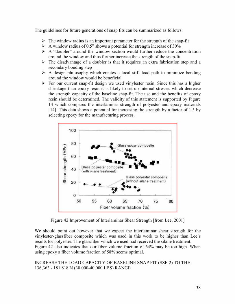
shrinkage than epoxy resin it is likely to set-up internal stresses which decrease the strength capacity of the baseline snap-fit. The use and the benefits of epoxy resin should be determined. The validity of this statement is supported by Figure 14 which compares the interlaminar strength of polyester and epoxy materials [14]. This data shows a potential for increasing the strength by a factor of 1.5 by selecting epoxy for the manufacturing process.
Figure 42 Improvement of Interlaminar Shear Strength [from Lee, 2001]
We should point out however that we expect the interlaminar shear strength for the vinylester-glassfiber composite which was used in this work to be higher than Lee’s results for polyester. The glassfiber which we used had received the silane treatment. Figure 42 also indicates that our fiber volume fraction of 64% may be too high. When using epoxy a fiber volume fraction of 58% seems optimal.
INCREASE THE LOAD CAPACITY OF BASELINE SNAP FIT (SSF-2) TO THE 136,363 - 181,818 N (30,000-40,000 LBS) RANGE
38

It was determined from the analysis that a radius of 12.5 mm (0.5”), as shown in Figure 43, would have a beneficial effect on load capacity and at the same time be manufacturable.
Figure 43 Snap-fit Geometry change for increased load capacity
It is noted from Figure 42c that the cross-member insert also needed to be radiussed in order to fit into the window.
Figure 44 illustrates the improvement in the local stress distribution at the rounded window corner. As was the case for the benchmark snap-fit, this stress distribution was observed at a load level of 22,727 N (5000 lbs).
Figure 44 Photoelastic result with rounded window corner
As before, we labeled the fringes and observed that they are slightly higher than 4 at the corner. This means that the stress concentration is roughly half of what is was before.
Figure 45 shows the cracking that emerged from the rounded window.
39

(a) (b) (c) Figure 45 Cracking at rounded window
The load capacity due to the reduced stress concentration increased to 127,272 N (28,000 lbs). This is within the expectations which we outlined in our Phase-I proposal. We also expressed a goal in the Phase-I proposal to be able to increase the load capacity with only a 5% increase in weight. In actuality we reduced the weight slightly. Near the end of the load cycle, the snap-fit did experience extensive non-linear behavior. Evidence of this behavior is shown in Figure 18c. There is also evidence that instead of one crack at each corner the window now experiences at least two cracks at each corner.
A very reassuring observation for designers is that the snap-fit fails very gradually and keeps holding load. Even the heavily damaged section which is shown in Figure 18c was able to still carry 50% of the failure load.
No damage on the radiused cross-member insert was observed.
PRELIMINARY DESIGN OF INNOVATIVE SNAP-FT CONFIGURATIONS FOR THE 40,000 TO 50,000 LBS LOAD CAPACITY RANGE
In the design guidelines we mentioned that a doubler plate would be beneficial in order to increase the load capacity of the snap-fit. An improved configuration is shown in Figure 46.
40

Figure 46 Configuration with underlying metal/ composite doubler (plate)
The blue plate which has been inserted underneath the surface of the red truss member will be bonded to the inside of the top surface and restrain the cracking from occurring. The plate will also help reduce the bending effect into the corner and increase the shear effect. The material for the plate could be steel, but it would be preferred to use a non-corrosive material such as a toughened ceramic or quasi-isotropic carbon or boron composite. Another candidate may be Glare. For compression loading we propose a cage-like configuration.
During the project we generated an idea for a displacement measurement procedure on the snap-fit by means of an optical microscope. This displacement data would be transformed into strain data with appropriate third party software. It will be used as the basis for a presentation to one of the technical societies such as SAMPE (Society of Advanced Materials and Process Engineers) or SEM (Society for Experimental Mechanics)
The load requirements for the complete structural analysis we obtained from AASHTO [7] The analysis was performed with Pro-Mechanica and the results are summarized in Figure 4 7
41

Figure 47 Sign Truss Deflections in Horizontal and Vertical Direction
Following AASHTO specifications, a wind load of 80 mph was assumed. For a 25 ft tall sign structure this translates into a pressure of 25 psf. This wind pressure was applied to the entire face of the sign truss. For this load case the resulting maximum deflection was 4.94” The vertical load consisted of the own weight of the sign truss plus a 50 lbs/ linear foot distributed load over the entire free span of 90 ft. The added distributed load accounts for the weight of the signs. For this load case the resulting maximum deflection was 1.37.” This is L/790 which is well below the L/150 which is referred in section 10-2 of the AAHTO specification.
42

7. CONCLUSIONS AND RECOMMENDATIONS
In this project we successfully designed, manufactured, and assembled a overhead sign bridge structure.
This structure has been designed for pultrusion, and allows for fastenerless assembly, without the use of tools, with the exception of a few clamps. As such these newly designed structures have the potential to compete on cost with traditional steel construction.
A lightweight composite sign structure with a 90 foot clear span has been designed. This sign truss does not rely on fasteners but on a new “snap joint” which allows for rapid assembly. The “snap joint” which we designed has a load capacity which is well in excess of 22,000 lbs.
The weight of the composite sign truss is less than 1/3rd of the weight of the steel structure. As such it can be installed with light and less expensive lifting equipment.
In summary:
CSSI has designed, constructed and assembled a standard Overhead Highway Sign Bridge – two post truss type out of Fiber Reinforced Polymer (FRP) composite materials utilizing the pultrusion process. The design of the composite sign structure and sign bridge meets all of the requirements of the 1999 Caltrans Standard Specifications and Standard Plans, the 2001 AASHTO Standard Specifications for Structural Supports for Highway Signs, Luminaries and traffic Signals, 4th edition.
The Overhead Sign Bridge – two post truss type, has a span length of ninety (60) feet. The Overhead Sign Truss has a frame depth of ninety-six (96) inches.
All materials and tooling necessary for the fabrication of the Overhead Sign Bridge/Sign have been designed and/ or procured by CSSI. The basic materials are E-Glass for the fiber, and Vinylester for the resin system.
CSSI has developed the conceptual design for the FRP Composite Overhead Sign Bridge, posts, and connection details. Detailed drawings of the Overhead Sign Bridge/Sign Structure have been generated and include selected materials, material properties, fiber architecture, connection details, and assembly details.
CSSI has performed component structural analysis to verify structural performance as required in the 2001 AASHTO Standard Specifications for Highway Signs, Luminaries and traffic Signals, 4th edition, and to verify the structural integrity of the design.
CSSI has produced a 30 ft sign bridge section and a 60 foot sign bridge section. These are ready for field installation.
43

It is recommended that the lessons learned in this effort be applied to future overhead sign bridge designs. This will lead to structures which require virtually no maintenance, and which don’t have the fatigue and cracking issues which plague their aluminum and steel counterparts.
44

8. REFERENCES 1. J. Batchelor and J.F. Kelly, “The Possible Application of Temporary Composite
Structures within the British Rail Network,” Composite Structures 2 (1984) pp 245-259
2. MoDot, “Signal Mast Arm Failure Investigation,” RTD 03-010, July 2003 3. Kaczinski, M. R., Dexter, R.J. and Van Dien, J.P., “Fatigue-Resistant Design of
Cantilevered Signal, Sign, and Light Supports, Report to NCHRP, ATLSS Engineering Research Center, Lehigh University, Bethlehem, Pennsylvania
4. Personal Communication with Air Logistics Corporation on repair of fatigued aluminum sign structures for the State of New York
5. W.B. Goldsworthy and C. Hiel, “Composite Structures are a Snap,” pp 382-396, Second International Conference on Composites in Infrastructure, H. Saadatmanesh and M.R. Ehsani, Editors, Tucson, AZ 1998.
6. Ronald K. Jurgen, “Smart Cars and Highways go Global,” IEEE Spectrum, May 1991, pp 26-36.
7. AASHTO, “Standard Specifications for Structural Support for Highway Signs, th
Luminaires and Traffic Signals, 4 Edition, 2001. 8. John Gizinos, Editor, CALTRANS Standard Plans, July 1999 9. Clem Hiel, “Assembly of 30 ft truss as a demo snap-fit structure.” CSSI internal
report, February, 2008. 10. Griffel, “Handbook of Formulas for Stress and Strain,” Frederick Ungar
Publishing Co, New York, 1976. 11. Savin, Holes 12. Jean Avril, “Encyclopedie Vishay d’analyse des Contraintes,” Vishay-
Micromesures, 1974. 13. Introduction to Stress Analysis by the Photoelastic Coating Technique. Technical
Bulletin TDG-1, Photolastic Inc. 14. Zandman, Felix, “Never the Last Journey,” Schocken Books, New York, 1995 15. Hiel, C. “Calibration of PS-3A photoelastic sensitive sheet material.” CSSI
Internal Report, March 2008. 16. Dolan, T.J., Murray, W.M., and Drucker, D.C., “Photoelasticity,” in Handbook of
Experimental Stress Analysis, ed. By M. Hetenyi, John Wiley & Sons, New York, 1950, pp. 826-976.
17. Hobbs, J.W., Burguele, R.L. and Patterson, E.A., “Investigation into the Effect of the Nut Thread run-out on the stress-distribution in a bolt using the Finite Element Method, Journal of Mechanical Design, September 2003.
18. Venkatesan, S. and Kinzel, G.L., Reduction of Stress Concentration in Bolt-Nut Connectors,” Journal of Mechanical Design, November 2006.
19. Patran, Users Manual, 2007 20. Hiel, C. “Finite Element Analysis of Snap-Fit,” CSSI Report, May, 2008 21. Hiel, C. “Test Plan for Snap-Fit Connections,” CSSI Internal Report, February,
2008. 22. Lee, D.G., and Cheon, S.S., “Impact Characteristics of Glass Fiber Composites
with Respect to Fiber Volume Fraction, “Journal of Composite Materials,” Vol. 35, No1, pp27-55
45

APPENDIX
CONTRACT 59A0343
DRAWINGS
Drawing Description
P5007-0001 CONCEPT “I”
P5007-0002 CONCEPT “II”, 90 FT BRIDGE
P5007-0003 TENSILE TEST FIXTURE
P5007-0004 CROSS ARM ASSEMBLY
P5007-0005 BRACKET
P5007-0006 WIND BRACE
P5007-0007 TENSILE TEST FIXTURE, TOP CLAMP
P5007-0008 PULTRUSION DIE ASSEMBLY (PROFILE #1)
P5007-0009 PULTRUSION DIE (PROFILE #1)
P5007-0011 PULTRUSION DIE ASSEMBLY (PROFILE #2)
P5007-0012 PULTRUSION ASSEMBLY (PROFILE #1)
P5007-0013 FINISH MANDREL
P5007-0014 DIE SUPPRT BAR
P5007-0015 UPSTREAM TRACK
P5007-0016 PROFILE #1 – PLY SCHEDULE
T5007-0017 WET-OUT TANK WELDMENT
P5007-0020 PULTRUSION SET-UP
P5007-0021 PROFILE #2 – PLY SCHEDULE
46

T5007-0022 ANCHOR FOR PROFILE #2
P5007-0024 24’ SPAN BRIDGE ASSEMBLY
P5007-0026 TOP CHORD “A”,”B”
P5007-0028 BOTTOM CHORD “C”,“D”
P5007-0029 VERTICAL
P5007-0030 DIAGONAL
P5007-0031 WIND BRACE
P5007-0035 24’ SPAN BRIDGE –OVERHEAD TRUSS ASSEMBLY
P5007-0032 54’ SPAN BRIDGE ASSEMBLY
P5007-0033 54’ SPAN BRIDGE –OVERHEAD TRUSS ASSEMBLY
P5007-0114 ROUGH MANDREL TYPE “C” FARSIDE
P5007-0115 ROUGH MANDREL TYPE “C” FARSIDE
P5007-1004 LOCK PLY-SCHEDULE
T5007-1013 PULTRUSION ASSEMBLY (PROFILE #2)
P5007-1112 LOCK PROFILE
P5007-1113 LOCK PULTRUSION DIE
47

P5007-0001-1
48

P5007-0001-2
49

P5007-0002
50

P5007-0003
51

P5007-0004-1
52

P5007-0004-1
53

P5007-0004-2
54

P5007-0005
55

P5007-0006
56
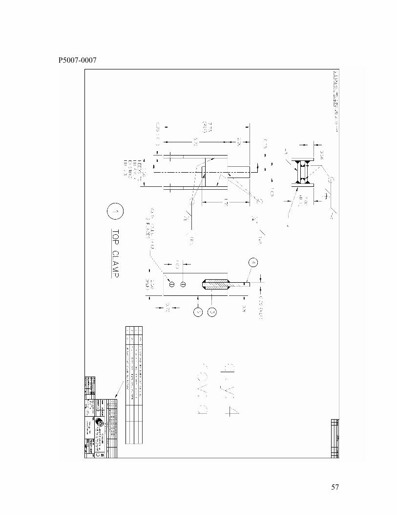
P5007-0007
57

P5007-0008
58

P5007-0009-1
59

P5007-0009-2
60

P5007-0009-3
61

P5007-00010
62

P5007-00011
63

T5007-00012-1
64
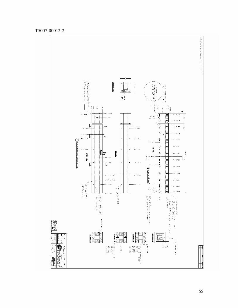
T5007-00012-2
65

T5007-00012-3
66

P5007-0013
67

P5007-0014
68

P5007-0015
69

P5007-0016
70

T5007-0017
71

P5007-0020
72

P5007-0021
73

P5007-0023
74

P5007-0024
75

P5007-0025
76

P5007-0026
77

P5007-0028
78

P5007-0029
79

P5007-0030
80

P5007-0031
81

P5007-0032
82

P5007-0033
83

P5007-0114-1
84

P5007-0114-2
85

P5007-0115-1
86

P5007-0115-2
87

P5007-1004
88

P5007-1013
89

P5007-1112
90

P5007-1113-2
91