smu02b v300r002c02 user manual 02
DESCRIPTION
manual usuarioTRANSCRIPT
SMU02B V300R002C02
User Manual
Issue 02
Date 2013-09-09
HUAWEI TECHNOLOGIES CO., LTD.
Issue 02 (2013-09-09) Huawei Proprietary and Confidential
Copyright © Huawei Technologies Co., Ltd. i
Copyright © Huawei Technologies Co., Ltd. 2013. All rights reserved.
No part of this document may be reproduced or transmitted in any form or by any means without prior
written consent of Huawei Technologies Co., Ltd.
Trademarks and Permissions
and other Huawei trademarks are trademarks of Huawei Technologies Co., Ltd.
All other trademarks and trade names mentioned in this document are the property of their respective
holders.
Notice
The purchased products, services and features are stipulated by the contract made between Huawei and
the customer. All or part of the products, services and features described in this document may not be
within the purchase scope or the usage scope. Unless otherwise specified in the contract, all statements,
information, and recommendations in this document are provided "AS IS" without warranties, guarantees or
representations of any kind, either express or implied.
The information in this document is subject to change without notice. Every effort has been made in the
preparation of this document to ensure accuracy of the contents, but all statements, information, and
recommendations in this document do not constitute a warranty of any kind, express or implied.
Huawei Technologies Co., Ltd.
Address: Huawei Industrial Base
Bantian, Longgang
Shenzhen 518129
People's Republic of China
Website: http://www.huawei.com
Email: [email protected]
SMU02B
User Manual About This Document
Issue 02 (2013-09-09) Huawei Proprietary and Confidential
Copyright © Huawei Technologies Co., Ltd.
ii
About This Document
Purpose
This document describes the site monitoring unit 02B (SMU02B) in terms of its hardware,
liquid crystal display (LCD), web user interface (WebUI), common operations, remote
management, and features.
Intended Audience
This document is intended for:
Sales engineers
Technical support personnel
Maintenance personnel
Symbol Conventions
The symbols that may be found in this document are defined as follows.
Symbol Description
Indicates a hazard with a high level or medium level of
risk which, if not avoided, could result in death or
serious injury.
Indicates a hazard with a low level of risk which, if not
avoided, could result in minor or moderate injury.
Indicates a potentially hazardous situation that, if not
avoided, could result in equipment damage, data loss,
performance deterioration, or unanticipated results.
Provides a tip that may help you solve a problem or save
time.
Provides additional information to emphasize or
supplement important points in the main text.
SMU02B
User Manual About This Document
Issue 02 (2013-09-09) Huawei Proprietary and Confidential
Copyright © Huawei Technologies Co., Ltd.
iii
Change History
Changes between document issues are cumulative. The latest document issue contains all the
changes made in earlier issues.
Issue 02 (2013-09-09)
Added section 8.5.4 "Solution 4: Heat Exchange and Direct Ventilation Unit".
The corresponding software version is V300R002C02.
Issue 01 (2013-07-15)
This issue is used for first office application (FOA).
The corresponding software version is V300R002C02.
SMU02B
User Manual Contents
Issue 02 (2013-09-09) Huawei Proprietary and Confidential
Copyright © Huawei Technologies Co., Ltd.
iv
Contents
About This Document .................................................................................................................... ii
1 Overview ......................................................................................................................................... 1
1.1 Introduction .................................................................................................................................................................. 1
1.2 Features ......................................................................................................................................................................... 5
2 Panels and Ports ............................................................................................................................ 7
2.1 SMU02B ....................................................................................................................................................................... 7
2.2 UIM02C ........................................................................................................................................................................ 9
2.3 UIM02D...................................................................................................................................................................... 12
3 Hardware Replacement .............................................................................................................. 15
3.1 Safety Precautions ...................................................................................................................................................... 15
3.2 Replacing the SMU ..................................................................................................................................................... 15
3.3 Replacing the UIM02C ............................................................................................................................................... 16
3.4 Replacing the UIM02D ............................................................................................................................................... 18
4 LCD ................................................................................................................................................ 20
4.1 LCD Menu Hierarchy ................................................................................................................................................. 20
4.2 Buttons ........................................................................................................................................................................ 22
4.3 Password ..................................................................................................................................................................... 22
5 WebUI............................................................................................................................................ 23
5.1 Preparations for Login ................................................................................................................................................ 23
5.1.1 Preparing the Operating Environment ..................................................................................................................... 23
5.1.2 Connecting a Communications Cable ...................................................................................................................... 23
5.1.3 Setting Parameters ................................................................................................................................................... 23
5.2 Login page .................................................................................................................................................................. 24
5.3 Home Page .................................................................................................................................................................. 25
5.4 Real-time Monitoring ................................................................................................................................................. 26
5.5 Querying Historical Data ............................................................................................................................................ 36
5.6 System Setting ............................................................................................................................................................ 38
5.7 Maintenance ................................................................................................................................................................ 43
6 Common Tasks ............................................................................................................................ 48
6.1 Common Installation Tasks ......................................................................................................................................... 48
SMU02B
User Manual Contents
Issue 02 (2013-09-09) Huawei Proprietary and Confidential
Copyright © Huawei Technologies Co., Ltd.
v
6.1.1 Setting the Display Language .................................................................................................................................. 48
6.1.2 Setting Basic Battery Parameters ............................................................................................................................. 49
6.1.3 Changing the Date and Time ................................................................................................................................... 51
6.1.4 Configuring an Alarm Tone ..................................................................................................................................... 52
6.1.5 Enabling or Disabling Alarms .................................................................................................................................. 54
6.1.6 Setting Alarm Severities .......................................................................................................................................... 56
6.1.7 Setting Alarm Associated Relays ............................................................................................................................. 58
6.1.8 Setting Alarm Action for Dry Contact Output ......................................................................................................... 60
6.1.9 Clearing Associations Between Alarms and Dry Contacts ...................................................................................... 62
6.1.10 Setting Alarm Conditions for Dry Contact Inputs.................................................................................................. 64
6.1.11 Modifying Dry Contact Input Names .................................................................................................................... 65
6.1.12 Testing the Relay ................................................................................................................................................... 65
6.2 Common Maintenance Tasks ...................................................................................................................................... 66
6.2.1 Backing Up the Current Settings ............................................................................................................................. 66
6.2.2 Importing a Configuration File ................................................................................................................................ 67
6.2.3 Restoring Factory Defaults ...................................................................................................................................... 67
6.2.4 Upgrading the Software ........................................................................................................................................... 69
6.2.5 Resetting the SMU ................................................................................................................................................... 69
6.2.6 Adding, Modifying, or Deleting Users..................................................................................................................... 71
6.2.7 Querying Active Alarms .......................................................................................................................................... 72
6.2.8 Querying and Clearing Historical Alarms ................................................................................................................ 72
6.2.9 Clearing the Rectifiers Failing in Communication .................................................................................................. 74
6.2.10 Exporting Historical Data ...................................................................................................................................... 75
6.2.11 Exporting Fault Data .............................................................................................................................................. 76
6.2.12 Exporting Electronic Labels .................................................................................................................................. 77
6.2.13 Manually Controlling a Power System .................................................................................................................. 78
7 Remote Management .................................................................................................................. 90
7.1 NetEco Management .................................................................................................................................................. 90
7.1.1 Networking Mode 1: over FE .................................................................................................................................. 90
7.1.2 Networking Mode 2: over an RS485/RS232 Port .................................................................................................... 92
7.2 EMS Management over SNMP .................................................................................................................................. 94
7.2.1 Site Configuration .................................................................................................................................................... 94
7.2.2 Setting SNMP Parameters ........................................................................................................................................ 95
7.2.3 EMS Commissioning ............................................................................................................................................... 98
8 Feature Description..................................................................................................................... 99
8.1 Rectifier Management................................................................................................................................................. 99
8.1.1 Controlling Rectifier Output Voltages ..................................................................................................................... 99
8.1.2 Controlling Rectifier Output Currents ................................................................................................................... 101
8.1.3 (Optional) Starting Rectifiers Sequentially ............................................................................................................ 104
8.2 Energy Conservation Management ........................................................................................................................... 106
8.2.1 Intelligent Rectifier Hibernation ............................................................................................................................ 106
SMU02B
User Manual Contents
Issue 02 (2013-09-09) Huawei Proprietary and Confidential
Copyright © Huawei Technologies Co., Ltd.
vi
8.3 Power Segment Management ................................................................................................................................... 110
8.4 Lead-Acid Battery Management ............................................................................................................................... 117
8.4.1 Charging Management ........................................................................................................................................... 117
8.4.2 Fast Charging ......................................................................................................................................................... 122
8.4.3 Temperature Compensation ................................................................................................................................... 126
8.4.4 High and Low Temperature Alarm and Protection ................................................................................................ 129
8.4.5 Standard Battery Test ............................................................................................................................................. 131
8.4.6 Short Test ............................................................................................................................................................... 138
8.4.7 Presence and Balance Detection ............................................................................................................................ 142
8.4.8 Remaining Battery Capacity and Backup Time Forecasting ................................................................................. 147
8.4.9 Intelligent Battery Hibernation .............................................................................................................................. 147
8.5 Temperature Control ................................................................................................................................................. 150
8.5.1 Solution 1: AC Air Conditioner and Direct Ventilation Unit ................................................................................. 150
8.5.2 Solution 2: Direct Ventilation Unit and Heater ...................................................................................................... 162
8.5.3 Solution 3: DC Air Conditioner and Direct Ventilation Unit ................................................................................. 171
8.5.4 Solution 4: Heat Exchange and Direct Ventilation Unit ........................................................................................ 180
8.6 D.G. Management ..................................................................................................................................................... 186
8.6.1 Power Limitation ................................................................................................................................................... 186
8.6.2 D.G.-Mains-Battery Alternation ............................................................................................................................. 190
8.6.3 Scheduled D.G. Shutdown ..................................................................................................................................... 198
8.7 Programmable Logic Controller ............................................................................................................................... 202
8.8 Data Recording and Performance Statistics .............................................................................................................. 209
8.8.1 Data Recording ...................................................................................................................................................... 209
8.8.2 Performance Statistics ............................................................................................................................................ 213
A LCD Menu Hierarchy .............................................................................................................. 217
B Alarm Description .................................................................................................................... 235
SMU02B
User Manual 1 Overview
Issue 02 (2013-09-09) Huawei Proprietary and Confidential
Copyright © Huawei Technologies Co., Ltd.
1
1 Overview
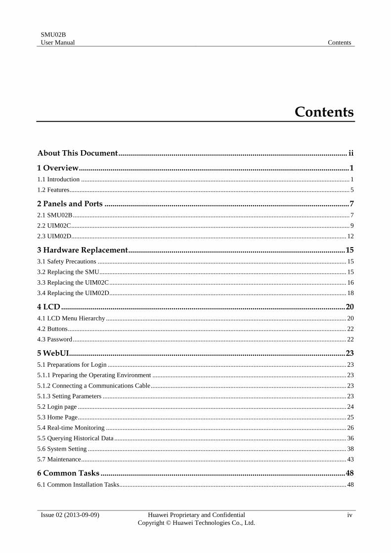
1.1 Introduction
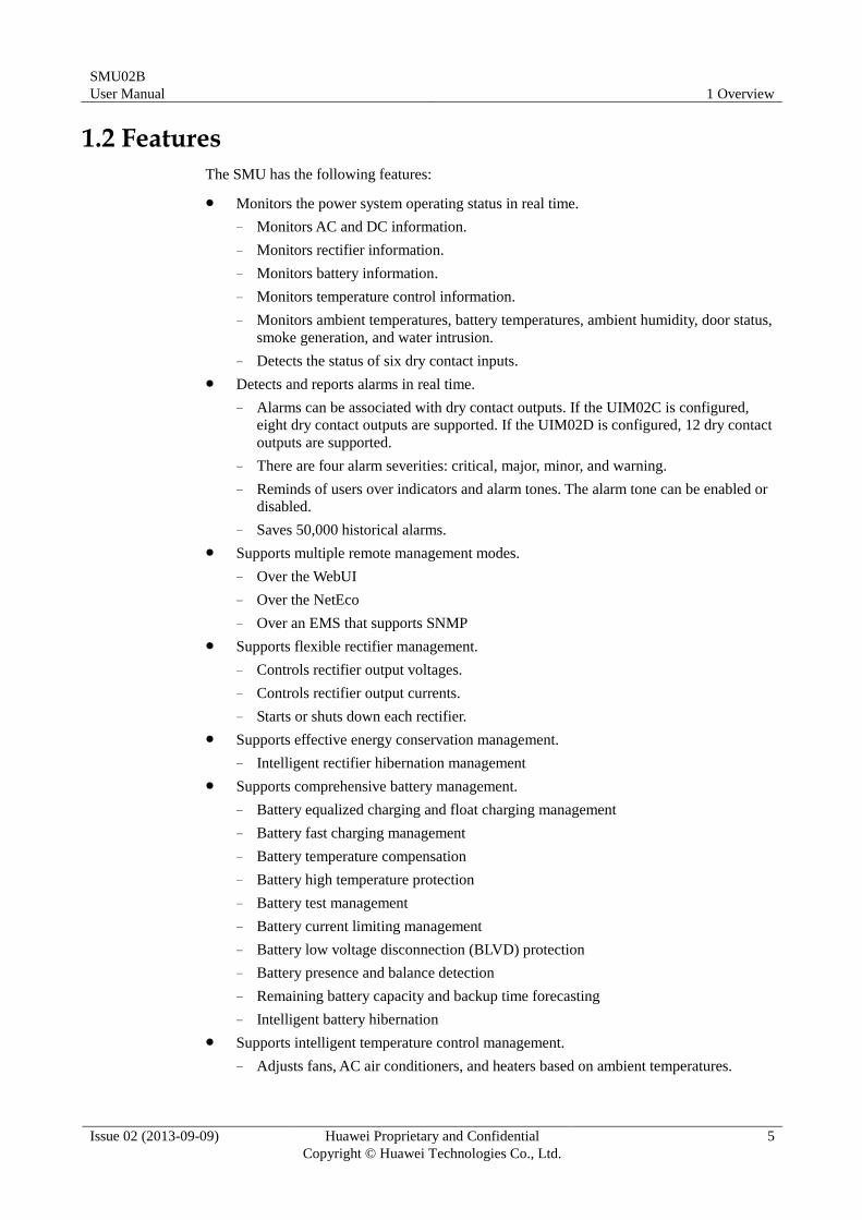
The SMU is a small-sized high-end monitoring module that monitors and manages Huawei
box-type and cabinet-type power systems.
You can access the SMU over Huawei NetEco, third-party element management systems
(EMSs) that support the Simple Network Management Protocol (SNMP), or a WebUI to
remotely manage power systems.
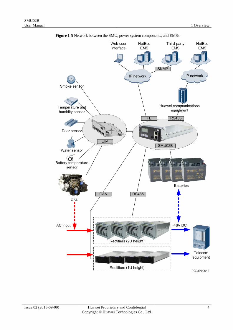
By configured with the user interface module 02C (UIM02C) or UIM02D (MUS01A), the
SMU provides sensor ports, an RS485 port, dry contact inputs, and dry contact outputs for
managing the environment inside the cabinet and reporting alarms.
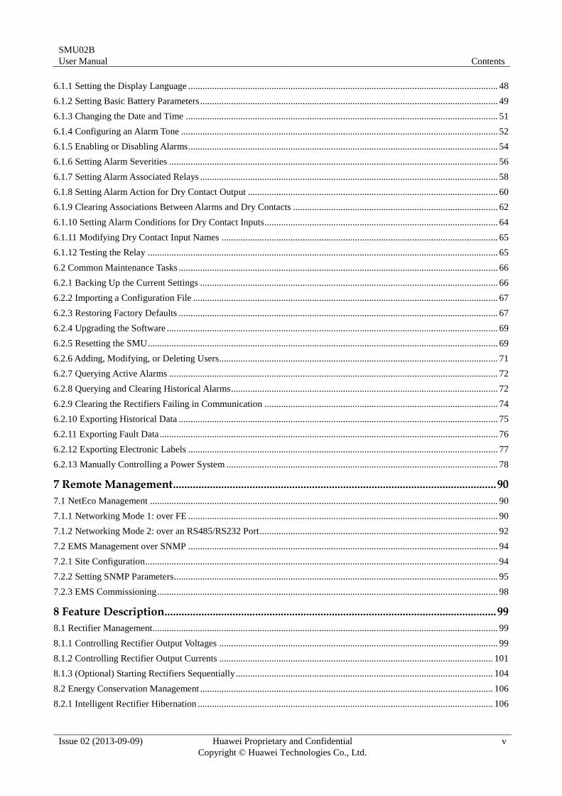
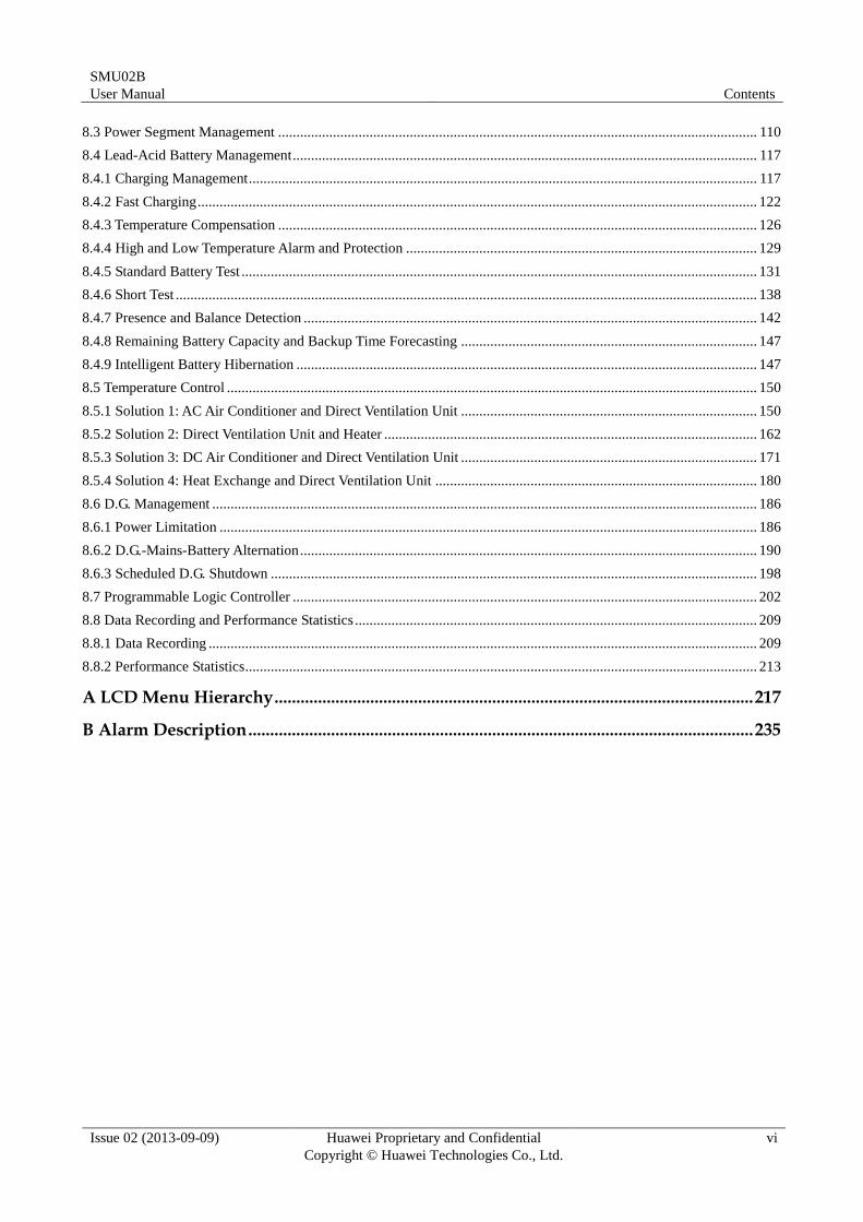
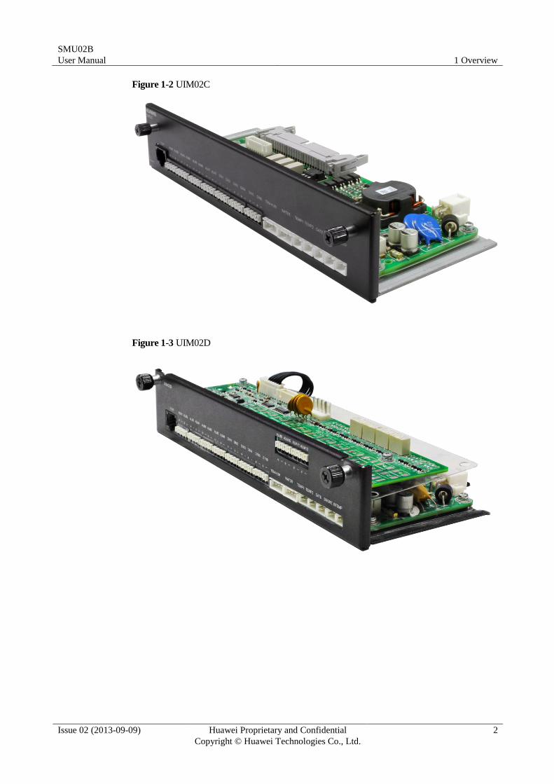
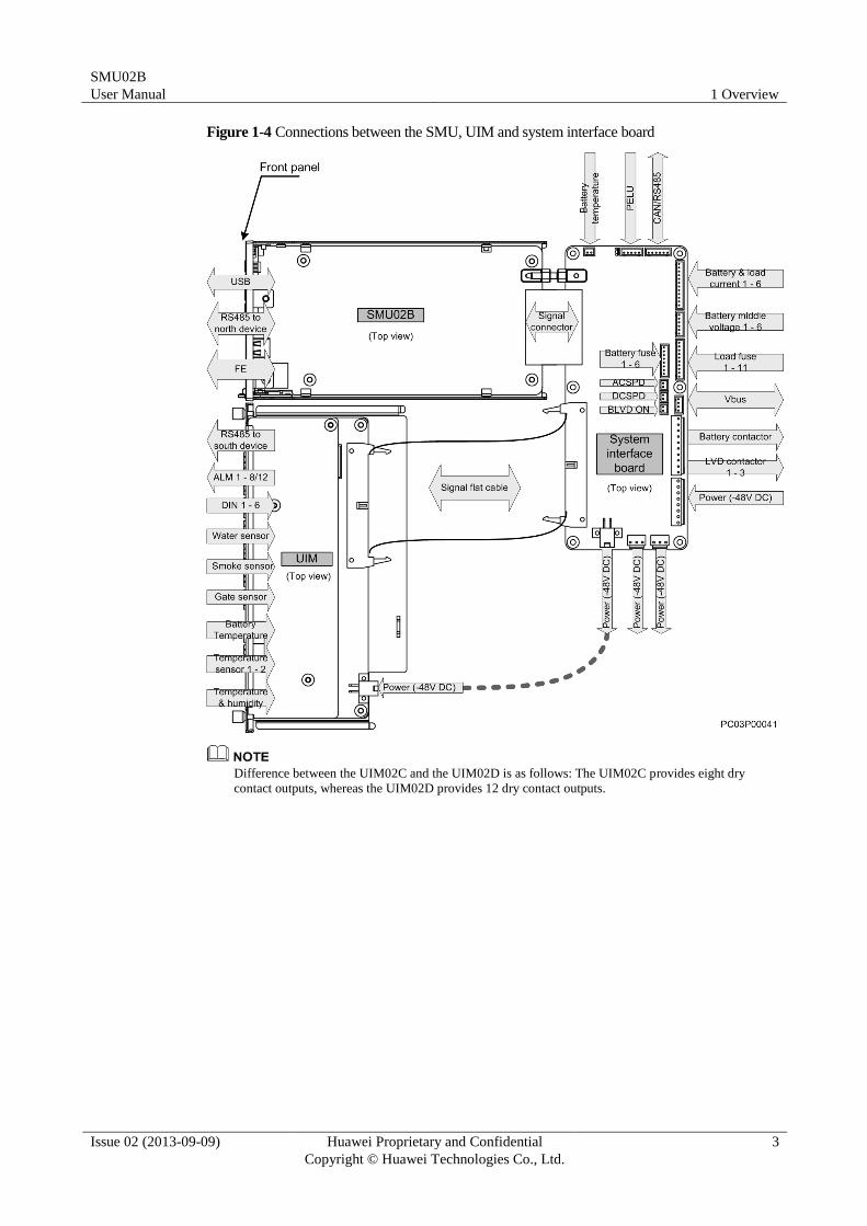
Figure 1-1 shows an SMU, Figure 1-2 shows a UIM02C, and Figure 1-3 shows a UIM02D.
Figure 1-4 shows the connections between the SMU, UIM, and system interface board. Figure
1-5 shows the network between the SMU, power system components, and EMSs.
Figure 1-1 SMU
SMU02B
User Manual 1 Overview
Issue 02 (2013-09-09) Huawei Proprietary and Confidential
Copyright © Huawei Technologies Co., Ltd.
2
Figure 1-2 UIM02C
Figure 1-3 UIM02D
SMU02B
User Manual 1 Overview
Issue 02 (2013-09-09) Huawei Proprietary and Confidential
Copyright © Huawei Technologies Co., Ltd.
3
Figure 1-4 Connections between the SMU, UIM and system interface board
Difference between the UIM02C and the UIM02D is as follows: The UIM02C provides eight dry
contact outputs, whereas the UIM02D provides 12 dry contact outputs.
SMU02B
User Manual 1 Overview
Issue 02 (2013-09-09) Huawei Proprietary and Confidential
Copyright © Huawei Technologies Co., Ltd.
4
Figure 1-5 Network between the SMU, power system components, and EMSs
SMU02B
User Manual 1 Overview
Issue 02 (2013-09-09) Huawei Proprietary and Confidential
Copyright © Huawei Technologies Co., Ltd.
5
1.2 Features
The SMU has the following features:
Monitors the power system operating status in real time.
− Monitors AC and DC information.
− Monitors rectifier information.
− Monitors battery information.
− Monitors temperature control information.
− Monitors ambient temperatures, battery temperatures, ambient humidity, door status,
smoke generation, and water intrusion.
− Detects the status of six dry contact inputs.
Detects and reports alarms in real time.
− Alarms can be associated with dry contact outputs. If the UIM02C is configured,
eight dry contact outputs are supported. If the UIM02D is configured, 12 dry contact
outputs are supported.
− There are four alarm severities: critical, major, minor, and warning.
− Reminds of users over indicators and alarm tones. The alarm tone can be enabled or
disabled.
− Saves 50,000 historical alarms.
Supports multiple remote management modes.
− Over the WebUI
− Over the NetEco
− Over an EMS that supports SNMP
Supports flexible rectifier management.
− Controls rectifier output voltages.
− Controls rectifier output currents.
− Starts or shuts down each rectifier.
Supports effective energy conservation management.
− Intelligent rectifier hibernation management
Supports comprehensive battery management.
− Battery equalized charging and float charging management
− Battery fast charging management
− Battery temperature compensation
− Battery high temperature protection
− Battery test management
− Battery current limiting management
− Battery low voltage disconnection (BLVD) protection
− Battery presence and balance detection
− Remaining battery capacity and backup time forecasting
− Intelligent battery hibernation
Supports intelligent temperature control management.
− Adjusts fans, AC air conditioners, and heaters based on ambient temperatures.
SMU02B
User Manual 1 Overview
Issue 02 (2013-09-09) Huawei Proprietary and Confidential
Copyright © Huawei Technologies Co., Ltd.
6
Supports intelligent diesel generator (D.G.) management.
− Switches between the D.G. and batteries based on the power supply of the power
system to save energy.
− Limits rectifier output power based on the D.G. capacity and loading percentage of
the power system to ensure normal load operating.
Supports flexible and programmable logic control.
− Selects any signals (such as those indicating DC undervoltage, D.G. operating, and
AC power failures) and performs logical operations on them, such as AND, OR,
NOT, >, <, and then sends calculation results to reserved dry contacts.
Supports detailed data records and performance statistics.
SMU02B
User Manual 2 Panels and Ports
Issue 02 (2013-09-09) Huawei Proprietary and Confidential
Copyright © Huawei Technologies Co., Ltd.
7
2 Panels and Ports
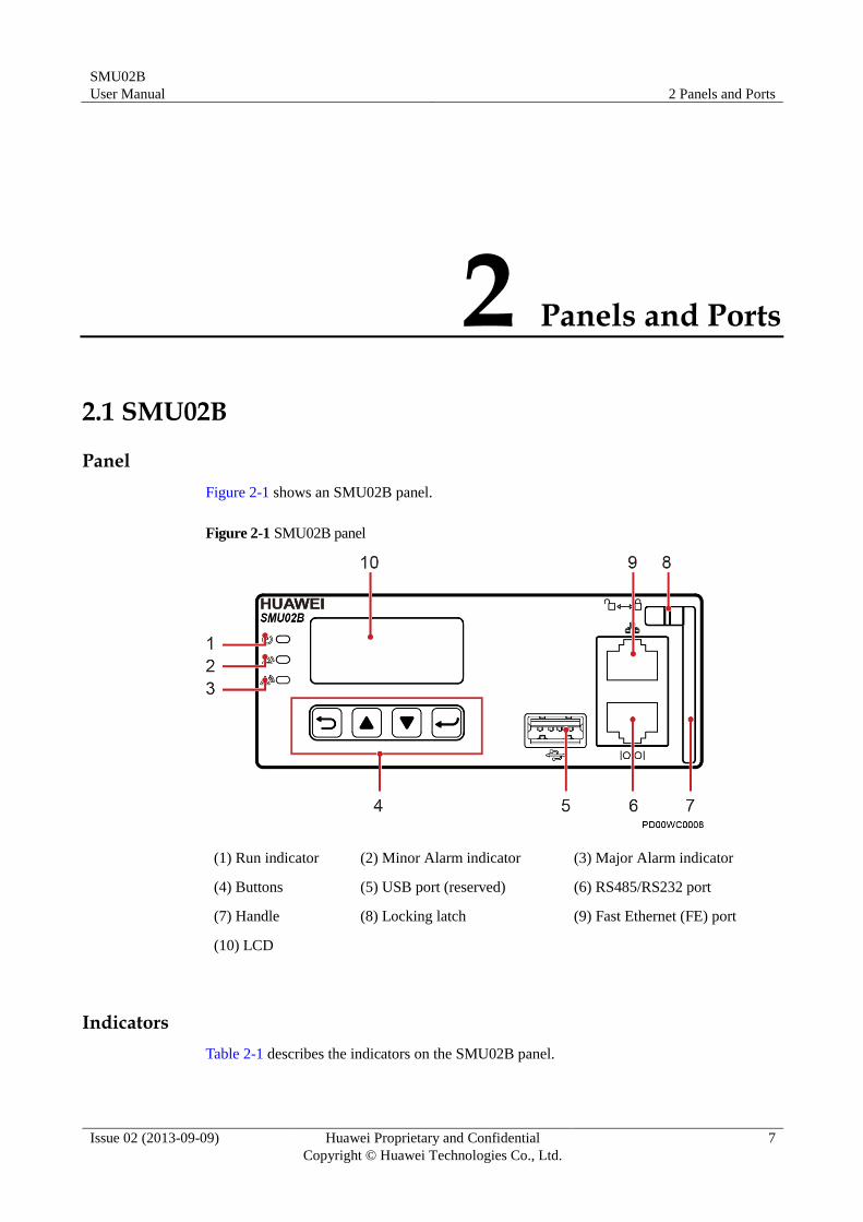
2.1 SMU02B
Panel
Figure 2-1 shows an SMU02B panel.
Figure 2-1 SMU02B panel
(1) Run indicator (2) Minor Alarm indicator (3) Major Alarm indicator
(4) Buttons (5) USB port (reserved) (6) RS485/RS232 port
(7) Handle (8) Locking latch (9) Fast Ethernet (FE) port
(10) LCD
Indicators
Table 2-1 describes the indicators on the SMU02B panel.
SMU02B
User Manual 2 Panels and Ports
Issue 02 (2013-09-09) Huawei Proprietary and Confidential
Copyright © Huawei Technologies Co., Ltd.
8
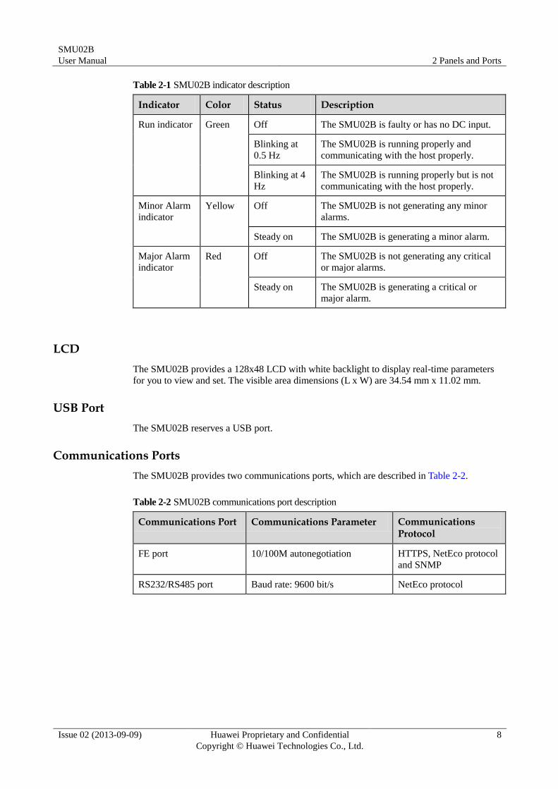
Table 2-1 SMU02B indicator description
Indicator Color Status Description
Run indicator Green Off The SMU02B is faulty or has no DC input.
Blinking at
0.5 Hz
The SMU02B is running properly and
communicating with the host properly.
Blinking at 4
Hz
The SMU02B is running properly but is not
communicating with the host properly.
Minor Alarm
indicator
Yellow Off The SMU02B is not generating any minor
alarms.
Steady on The SMU02B is generating a minor alarm.
Major Alarm
indicator
Red Off The SMU02B is not generating any critical
or major alarms.
Steady on The SMU02B is generating a critical or
major alarm.
LCD
The SMU02B provides a 128x48 LCD with white backlight to display real-time parameters
for you to view and set. The visible area dimensions (L x W) are 34.54 mm x 11.02 mm.
USB Port
The SMU02B reserves a USB port.
Communications Ports
The SMU02B provides two communications ports, which are described in Table 2-2.
Table 2-2 SMU02B communications port description
Communications Port Communications Parameter Communications Protocol
FE port 10/100M autonegotiation HTTPS, NetEco protocol
and SNMP
RS232/RS485 port Baud rate: 9600 bit/s NetEco protocol
SMU02B
User Manual 2 Panels and Ports
Issue 02 (2013-09-09) Huawei Proprietary and Confidential
Copyright © Huawei Technologies Co., Ltd.
9
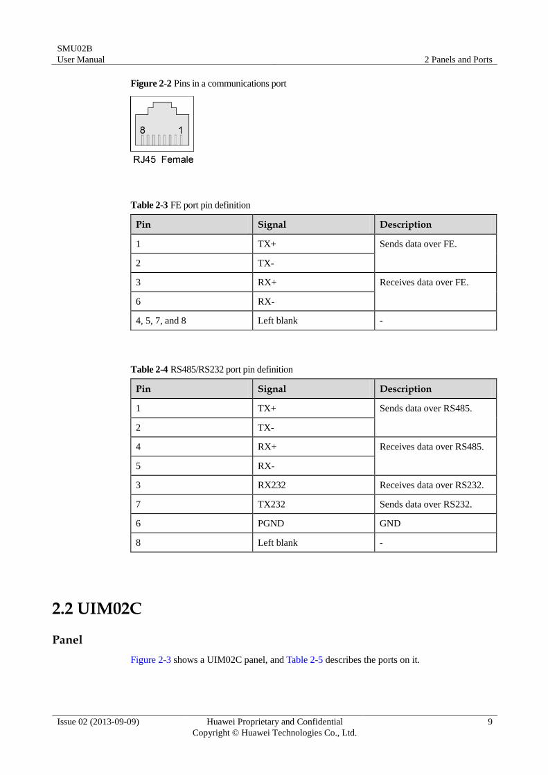
Figure 2-2 Pins in a communications port
Table 2-3 FE port pin definition
Pin Signal Description
1 TX+ Sends data over FE.
2 TX-
3 RX+ Receives data over FE.
6 RX-
4, 5, 7, and 8 Left blank -
Table 2-4 RS485/RS232 port pin definition
Pin Signal Description
1 TX+ Sends data over RS485.
2 TX-
4 RX+ Receives data over RS485.
5 RX-
3 RX232 Receives data over RS232.
7 TX232 Sends data over RS232.
6 PGND GND
8 Left blank -
2.2 UIM02C
Panel
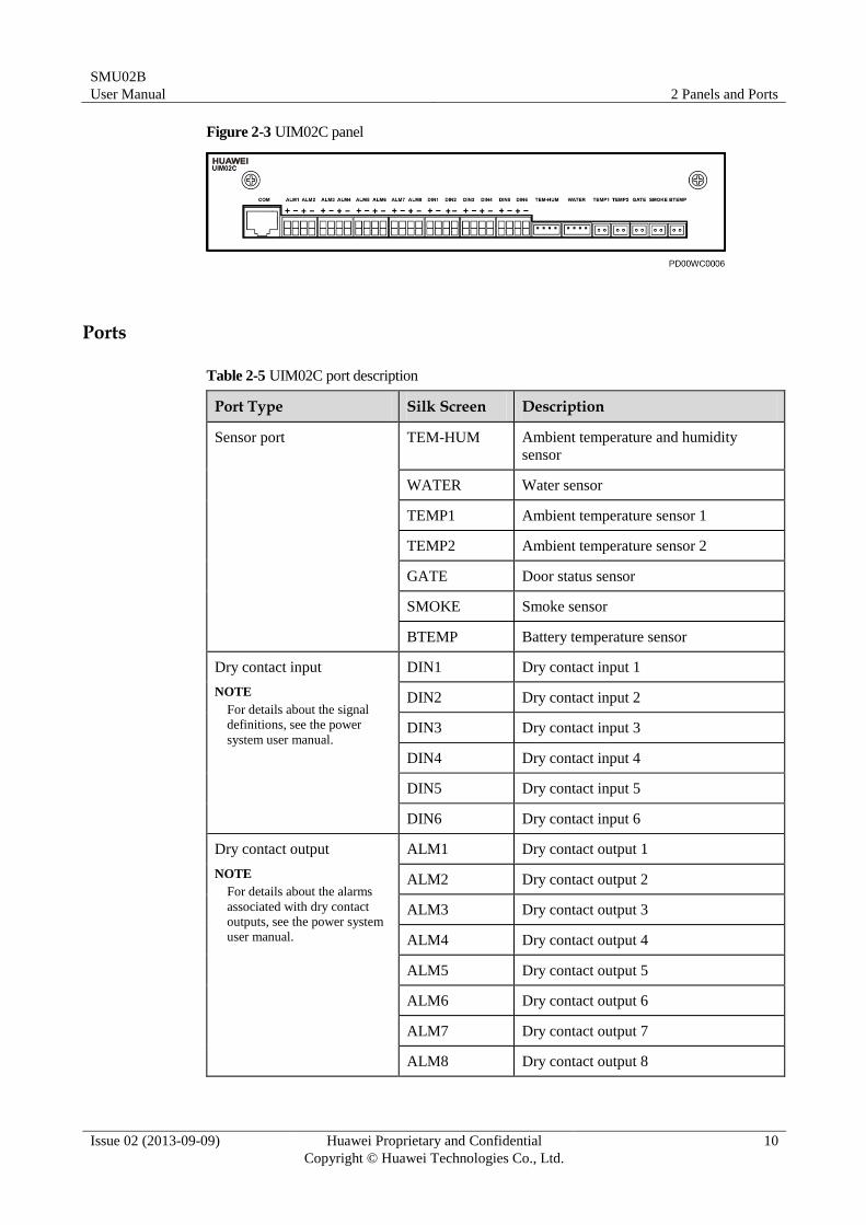
Figure 2-3 shows a UIM02C panel, and Table 2-5 describes the ports on it.
SMU02B
User Manual 2 Panels and Ports
Issue 02 (2013-09-09) Huawei Proprietary and Confidential
Copyright © Huawei Technologies Co., Ltd.
10
Figure 2-3 UIM02C panel
Ports
Table 2-5 UIM02C port description
Port Type Silk Screen Description
Sensor port TEM-HUM Ambient temperature and humidity
sensor
WATER Water sensor
TEMP1 Ambient temperature sensor 1
TEMP2 Ambient temperature sensor 2
GATE Door status sensor
SMOKE Smoke sensor
BTEMP Battery temperature sensor
Dry contact input
NOTE
For details about the signal
definitions, see the power
system user manual.
DIN1 Dry contact input 1
DIN2 Dry contact input 2
DIN3 Dry contact input 3
DIN4 Dry contact input 4
DIN5 Dry contact input 5
DIN6 Dry contact input 6
Dry contact output
NOTE
For details about the alarms
associated with dry contact
outputs, see the power system
user manual.
ALM1 Dry contact output 1
ALM2 Dry contact output 2
ALM3 Dry contact output 3
ALM4 Dry contact output 4
ALM5 Dry contact output 5
ALM6 Dry contact output 6
ALM7 Dry contact output 7
ALM8 Dry contact output 8
SMU02B
User Manual 2 Panels and Ports
Issue 02 (2013-09-09) Huawei Proprietary and Confidential
Copyright © Huawei Technologies Co., Ltd.
11
Port Type Silk Screen Description
Communications port COM RS485 port
Pins
Figure 2-4 shows the numbers of pins in sensor ports. Table 2-6 describes the pin definitions.
Figure 2-4 UIM02C pin numbers
Table 2-6 UIM02C pin definitions
Silk Screen No. Pins
TEM-HUM 1 12 V
2 ENV_TEMP
3 12 V
4 ENV_HUM
WATER 1 12 V
2 WATER
3 GND
4 -
TEMP1 1 TEMP1
2 GND
TEMP2 1 TEMP2
2 GND
GATE 1 DIN7+
2 JTD7
SMOKE 1 12 V
2 SMOKE
SMU02B
User Manual 2 Panels and Ports
Issue 02 (2013-09-09) Huawei Proprietary and Confidential
Copyright © Huawei Technologies Co., Ltd.
12
Silk Screen No. Pins
BTEMP 1 BTEM1
2 GND
2.3 UIM02D
Panel
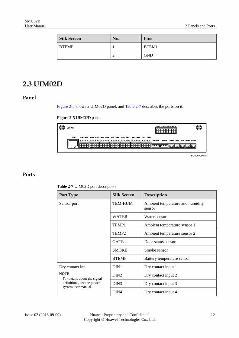
Figure 2-5 shows a UIM02D panel, and Table 2-7 describes the ports on it.
Figure 2-5 UIM02D panel
Ports
Table 2-7 UIM02D port description
Port Type Silk Screen Description
Sensor port TEM-HUM Ambient temperature and humidity
sensor
WATER Water sensor
TEMP1 Ambient temperature sensor 1
TEMP2 Ambient temperature sensor 2
GATE Door status sensor
SMOKE Smoke sensor
BTEMP Battery temperature sensor
Dry contact input
NOTE
For details about the signal
definitions, see the power
system user manual.
DIN1 Dry contact input 1
DIN2 Dry contact input 2
DIN3 Dry contact input 3
DIN4 Dry contact input 4
SMU02B
User Manual 2 Panels and Ports
Issue 02 (2013-09-09) Huawei Proprietary and Confidential
Copyright © Huawei Technologies Co., Ltd.
13
Port Type Silk Screen Description
DIN5 Dry contact input 5
DIN6 Dry contact input 6
Dry contact output
NOTE
For details about the alarms
associated with dry contact
outputs, see the power system
user manual.
ALM1 Dry contact output 1
ALM2 Dry contact output 2
ALM3 Dry contact output 3
ALM4 Dry contact output 4
ALM5 Dry contact output 5
ALM6 Dry contact output 6
ALM7 Dry contact output 7
ALM8 Dry contact output 8
ALM9 Dry contact output 9
ALM10 Dry contact output 10
ALM11 Dry contact output 11
ALM12 Dry contact output 12
Communications port COM RS485 port
Pins
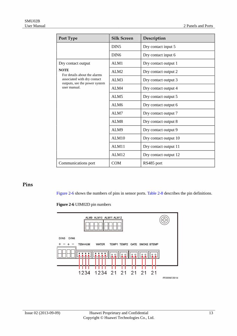
Figure 2-6 shows the numbers of pins in sensor ports. Table 2-8 describes the pin definitions.
Figure 2-6 UIM02D pin numbers
SMU02B
User Manual 2 Panels and Ports
Issue 02 (2013-09-09) Huawei Proprietary and Confidential
Copyright © Huawei Technologies Co., Ltd.
14
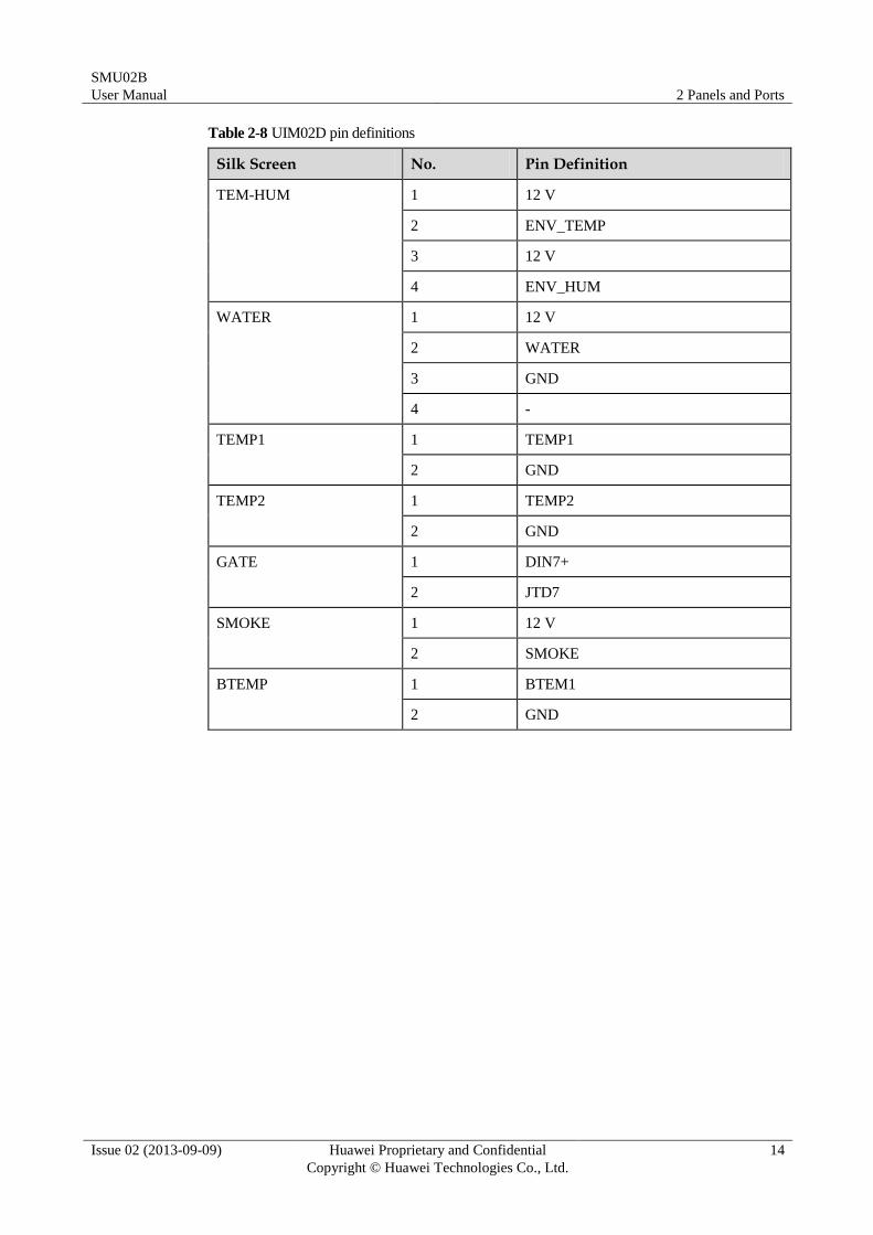
Table 2-8 UIM02D pin definitions
Silk Screen No. Pin Definition
TEM-HUM 1 12 V
2 ENV_TEMP
3 12 V
4 ENV_HUM
WATER 1 12 V
2 WATER
3 GND
4 -
TEMP1 1 TEMP1
2 GND
TEMP2 1 TEMP2
2 GND
GATE 1 DIN7+
2 JTD7
SMOKE 1 12 V
2 SMOKE
BTEMP 1 BTEM1
2 GND
SMU02B
User Manual 3 Hardware Replacement
Issue 02 (2013-09-09) Huawei Proprietary and Confidential
Copyright © Huawei Technologies Co., Ltd.
15
3 Hardware Replacement
3.1 Safety Precautions
When replacing the SMU and user interface module (UIM), wear electrostatic discharge (ESD)
gloves or an ESD wrist strap to avoid component damage.
3.2 Replacing the SMU
Context
The SMU is hot-swappable.
Procedure
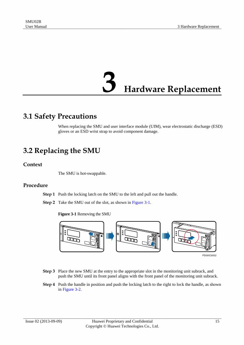
Step 1 Push the locking latch on the SMU to the left and pull out the handle.
Step 2 Take the SMU out of the slot, as shown in Figure 3-1.
Figure 3-1 Removing the SMU
Step 3 Place the new SMU at the entry to the appropriate slot in the monitoring unit subrack, and
push the SMU until its front panel aligns with the front panel of the monitoring unit subrack.
Step 4 Push the handle in position and push the locking latch to the right to lock the handle, as shown
in Figure 3-2.
SMU02B
User Manual 3 Hardware Replacement
Issue 02 (2013-09-09) Huawei Proprietary and Confidential
Copyright © Huawei Technologies Co., Ltd.
16
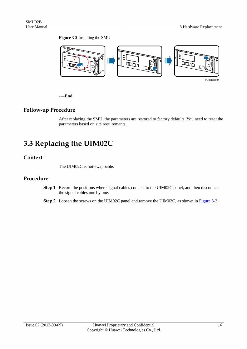
Figure 3-2 Installing the SMU
----End
Follow-up Procedure
After replacing the SMU, the parameters are restored to factory defaults. You need to reset the
parameters based on site requirements.
3.3 Replacing the UIM02C
Context
The UIM02C is hot-swappable.
Procedure
Step 1 Record the positions where signal cables connect to the UIM02C panel, and then disconnect
the signal cables one by one.
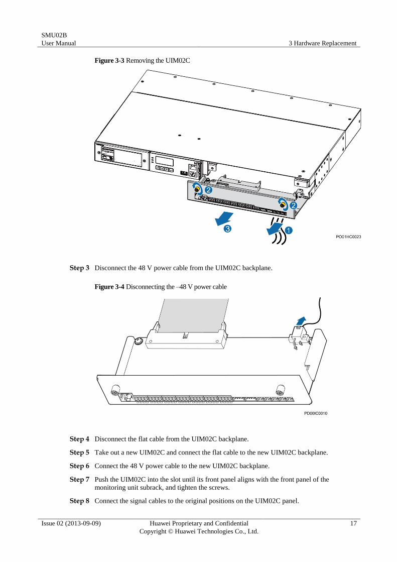
Step 2 Loosen the screws on the UIM02C panel and remove the UIM02C, as shown in Figure 3-3.
SMU02B
User Manual 3 Hardware Replacement
Issue 02 (2013-09-09) Huawei Proprietary and Confidential
Copyright © Huawei Technologies Co., Ltd.
17
Figure 3-3 Removing the UIM02C
Step 3 Disconnect the 48 V power cable from the UIM02C backplane.
Figure 3-4 Disconnecting the –48 V power cable
Step 4 Disconnect the flat cable from the UIM02C backplane.
Step 5 Take out a new UIM02C and connect the flat cable to the new UIM02C backplane.
Step 6 Connect the 48 V power cable to the new UIM02C backplane.
Step 7 Push the UIM02C into the slot until its front panel aligns with the front panel of the
monitoring unit subrack, and tighten the screws.
Step 8 Connect the signal cables to the original positions on the UIM02C panel.
SMU02B
User Manual 3 Hardware Replacement
Issue 02 (2013-09-09) Huawei Proprietary and Confidential
Copyright © Huawei Technologies Co., Ltd.
18
----End
3.4 Replacing the UIM02D
Context
The UIM02D is hot-swappable.
Procedure
Step 1 Record the positions where signal cables connect to the UIM02D panel, and then disconnect
the signal cables one by one.
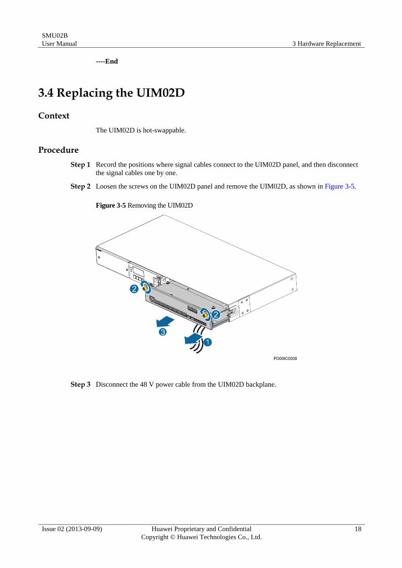
Step 2 Loosen the screws on the UIM02D panel and remove the UIM02D, as shown in Figure 3-5.
Figure 3-5 Removing the UIM02D
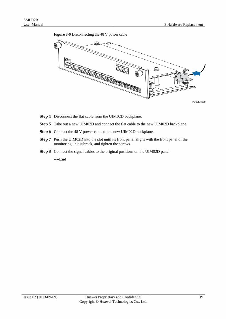
Step 3 Disconnect the 48 V power cable from the UIM02D backplane.
SMU02B
User Manual 3 Hardware Replacement
Issue 02 (2013-09-09) Huawei Proprietary and Confidential
Copyright © Huawei Technologies Co., Ltd.
19
Figure 3-6 Disconnecting the 48 V power cable
Step 4 Disconnect the flat cable from the UIM02D backplane.
Step 5 Take out a new UIM02D and connect the flat cable to the new UIM02D backplane.
Step 6 Connect the 48 V power cable to the new UIM02D backplane.
Step 7 Push the UIM02D into the slot until its front panel aligns with the front panel of the
monitoring unit subrack, and tighten the screws.
Step 8 Connect the signal cables to the original positions on the UIM02D panel.
----End
SMU02B
User Manual 4 LCD
Issue 02 (2013-09-09) Huawei Proprietary and Confidential
Copyright © Huawei Technologies Co., Ltd.
20
4 LCD
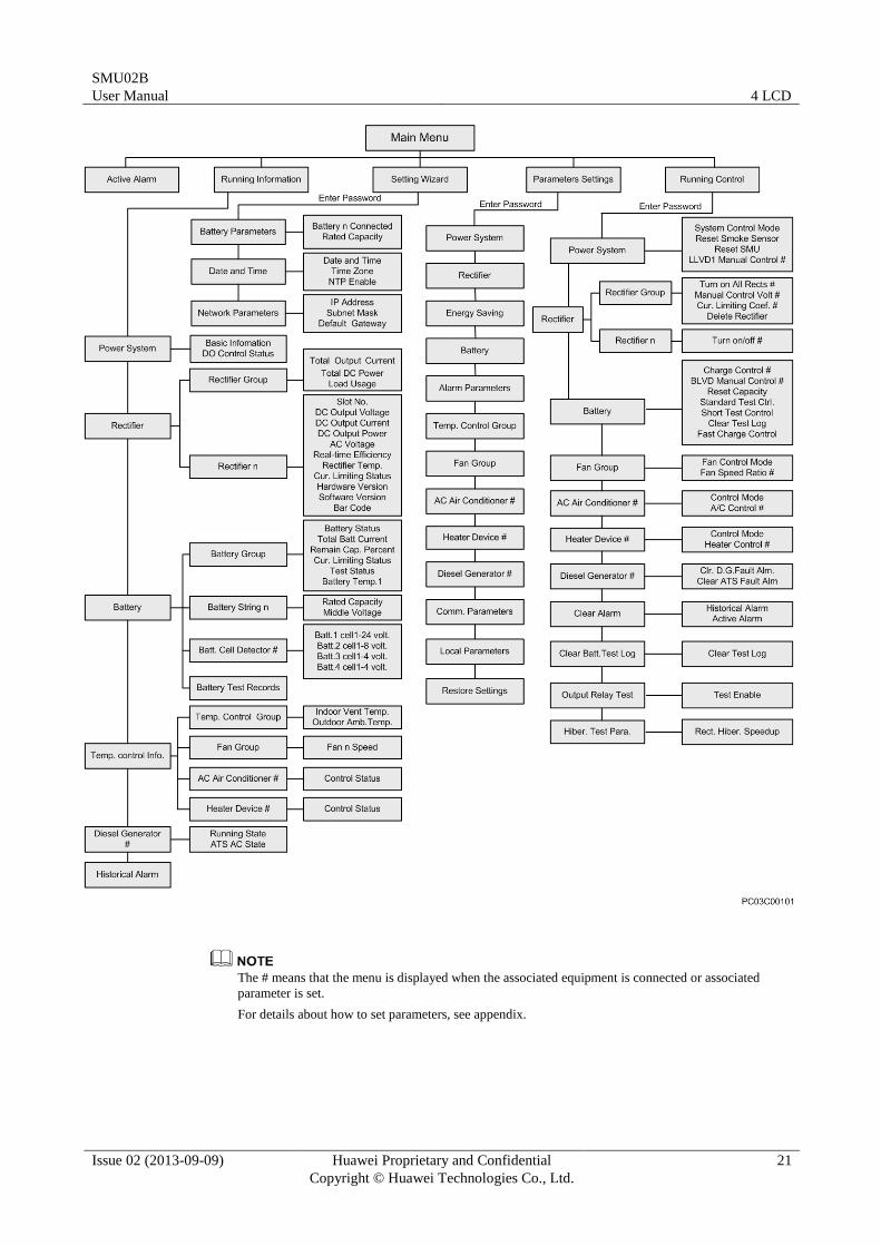
4.1 LCD Menu Hierarchy
Figure 4-1 LCD menu hierarchy
SMU02B
User Manual 4 LCD
Issue 02 (2013-09-09) Huawei Proprietary and Confidential
Copyright © Huawei Technologies Co., Ltd.
21
The # means that the menu is displayed when the associated equipment is connected or associated
parameter is set.
For details about how to set parameters, see appendix.
SMU02B
User Manual 4 LCD
Issue 02 (2013-09-09) Huawei Proprietary and Confidential
Copyright © Huawei Technologies Co., Ltd.
22
4.2 Buttons
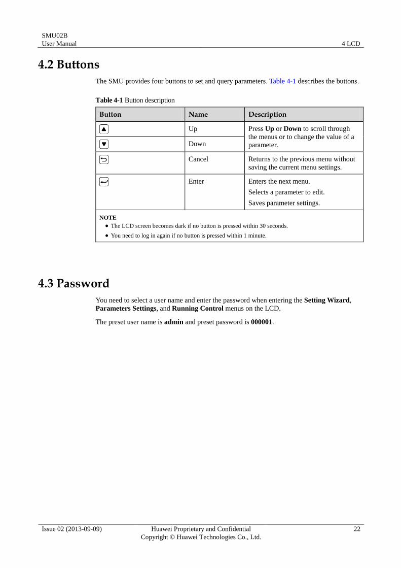
The SMU provides four buttons to set and query parameters. Table 4-1 describes the buttons.
Table 4-1 Button description
Button Name Description
Up Press Up or Down to scroll through
the menus or to change the value of a
parameter. Down
Cancel Returns to the previous menu without
saving the current menu settings.
Enter Enters the next menu.
Selects a parameter to edit.
Saves parameter settings.
NOTE
The LCD screen becomes dark if no button is pressed within 30 seconds.
You need to log in again if no button is pressed within 1 minute.
4.3 Password
You need to select a user name and enter the password when entering the Setting Wizard,
Parameters Settings, and Running Control menus on the LCD.
The preset user name is admin and preset password is 000001.
SMU02B
User Manual 5 WebUI
Issue 02 (2013-09-09) Huawei Proprietary and Confidential
Copyright © Huawei Technologies Co., Ltd.
23
5 WebUI
5.1 Preparations for Login
5.1.1 Preparing the Operating Environment
Operating system: Windows XP or later
Browser: Internet Explorer 7.0 or later, FireFox 5.0 or later, and Chrome1 6.0 or later
5.1.2 Connecting a Communications Cable
Procedure
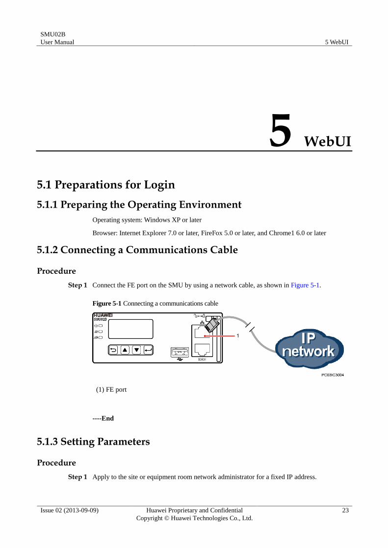
Step 1 Connect the FE port on the SMU by using a network cable, as shown in Figure 5-1.
Figure 5-1 Connecting a communications cable
(1) FE port
----End
5.1.3 Setting Parameters
Procedure
Step 1 Apply to the site or equipment room network administrator for a fixed IP address.
SMU02B
User Manual 5 WebUI
Issue 02 (2013-09-09) Huawei Proprietary and Confidential
Copyright © Huawei Technologies Co., Ltd.
24
Step 2 Set the IP address, subnet mask, and gateway on the LCD, as shown in Table 5-1.
Table 5-1 IP parameters
Main Menu Second-Level Menu
Third-Level Menu
Default Value Setting Value
Setting Wizard Network
Parameters
IP Address 192.168.0.10 Set this
parameter
according to the
address
assigned by the
network
administrator.
Subnet Mask 255.255.255.0 Set this
parameter
according to the
address
assigned by the
network
administrator.
Default
Gateway
192.168.0.1 Set this
parameter
according to the
address
assigned by the
network
administrator.
----End
5.2 Login page
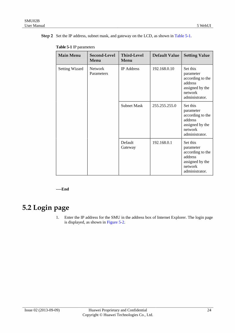
1. Enter the IP address for the SMU in the address box of Internet Explorer. The login page
is displayed, as shown in Figure 5-2.
SMU02B
User Manual 5 WebUI
Issue 02 (2013-09-09) Huawei Proprietary and Confidential
Copyright © Huawei Technologies Co., Ltd.
25
Figure 5-2 Login page
5.3 Home Page
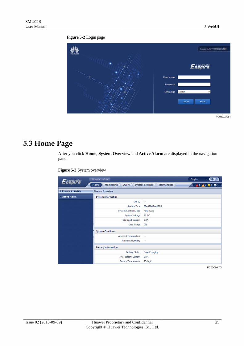
After you click Home, System Overview and Active Alarm are displayed in the navigation
pane.
Figure 5-3 System overview
SMU02B
User Manual 5 WebUI
Issue 02 (2013-09-09) Huawei Proprietary and Confidential
Copyright © Huawei Technologies Co., Ltd.
26
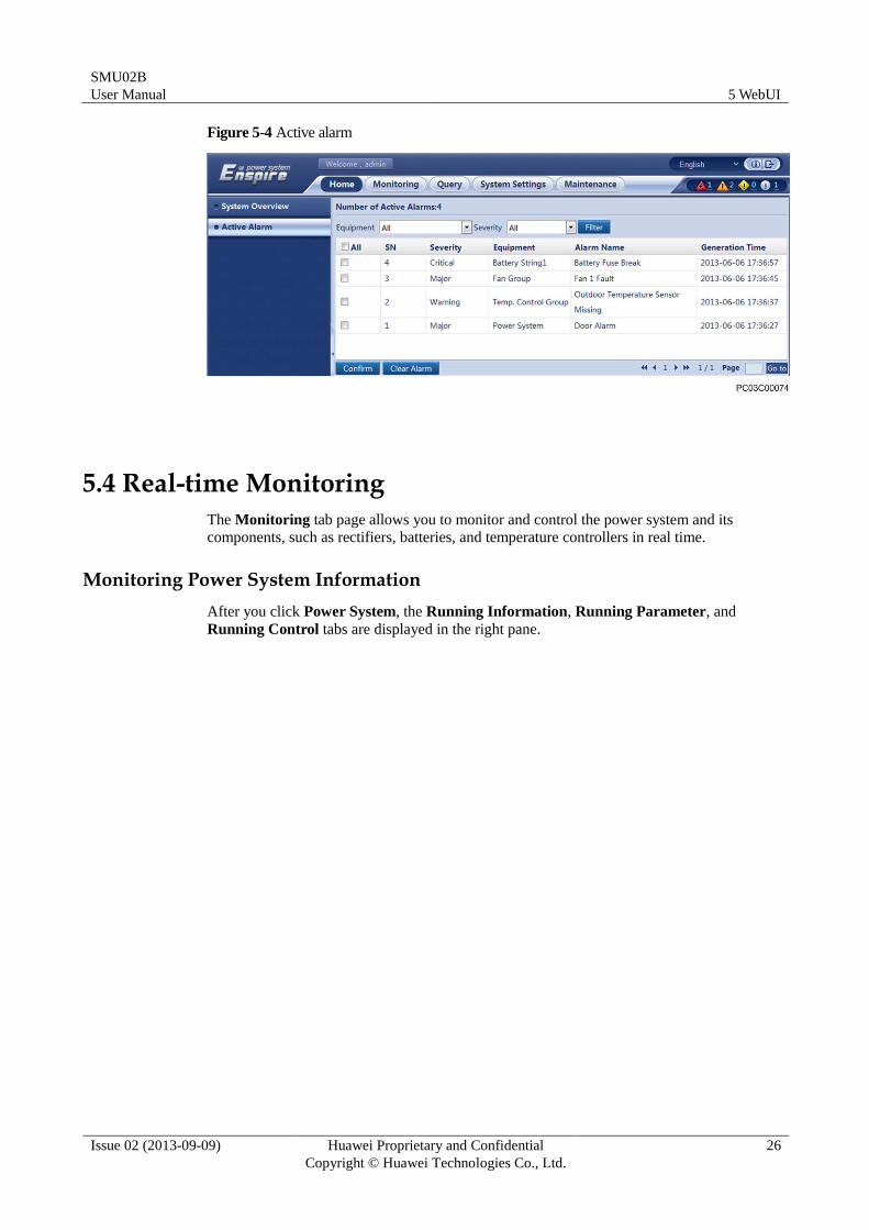
Figure 5-4 Active alarm
5.4 Real-time Monitoring
The Monitoring tab page allows you to monitor and control the power system and its
components, such as rectifiers, batteries, and temperature controllers in real time.
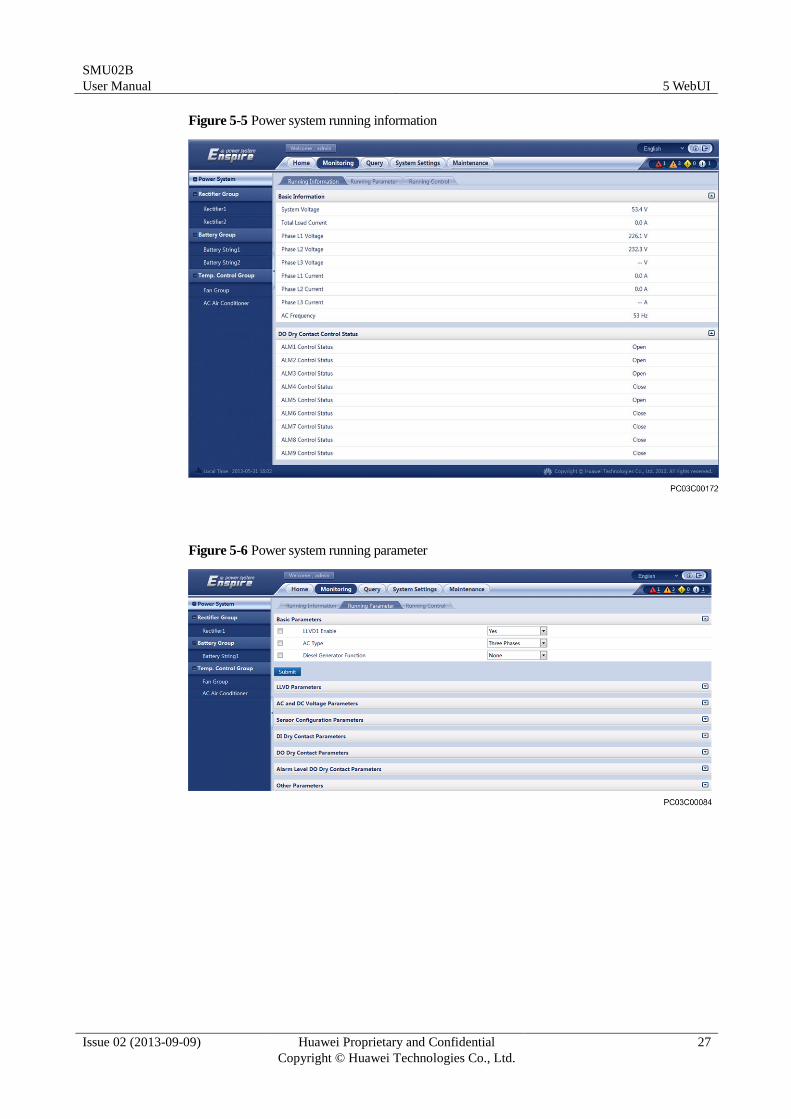
Monitoring Power System Information
After you click Power System, the Running Information, Running Parameter, and
Running Control tabs are displayed in the right pane.
SMU02B
User Manual 5 WebUI
Issue 02 (2013-09-09) Huawei Proprietary and Confidential
Copyright © Huawei Technologies Co., Ltd.
27
Figure 5-5 Power system running information
Figure 5-6 Power system running parameter
SMU02B
User Manual 5 WebUI
Issue 02 (2013-09-09) Huawei Proprietary and Confidential
Copyright © Huawei Technologies Co., Ltd.
28
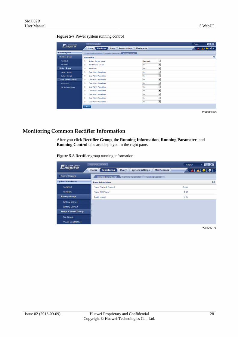
Figure 5-7 Power system running control
Monitoring Common Rectifier Information
After you click Rectifier Group, the Running Information, Running Parameter, and
Running Control tabs are displayed in the right pane.
Figure 5-8 Rectifier group running information
SMU02B
User Manual 5 WebUI
Issue 02 (2013-09-09) Huawei Proprietary and Confidential
Copyright © Huawei Technologies Co., Ltd.
29
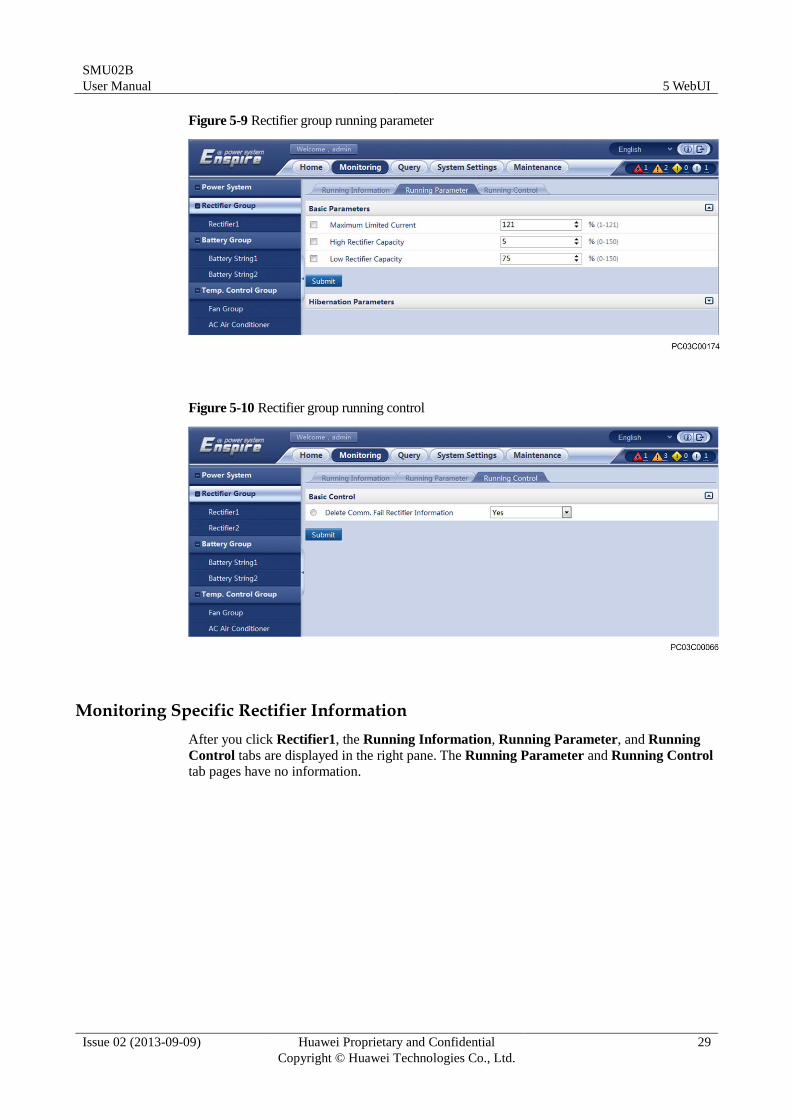
Figure 5-9 Rectifier group running parameter
Figure 5-10 Rectifier group running control
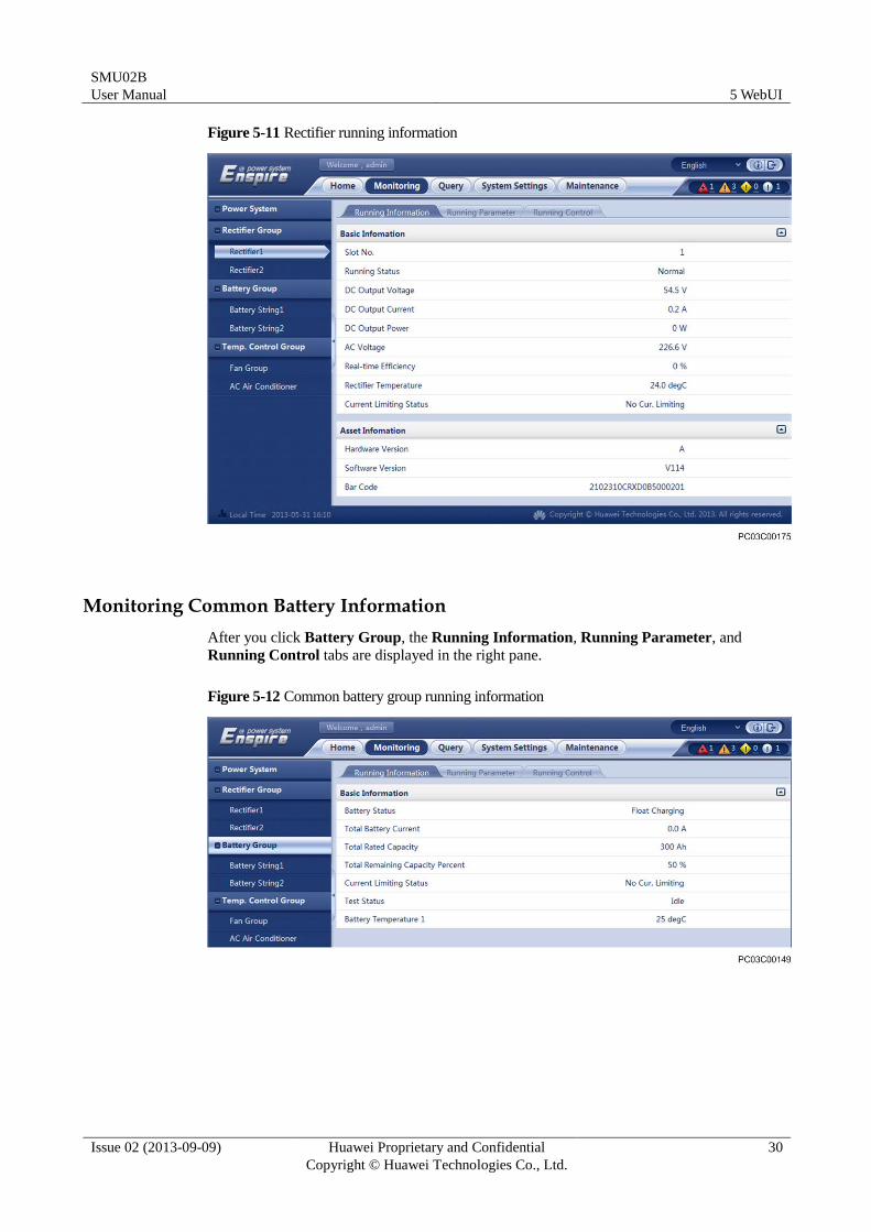
Monitoring Specific Rectifier Information
After you click Rectifier1, the Running Information, Running Parameter, and Running
Control tabs are displayed in the right pane. The Running Parameter and Running Control
tab pages have no information.
SMU02B
User Manual 5 WebUI
Issue 02 (2013-09-09) Huawei Proprietary and Confidential
Copyright © Huawei Technologies Co., Ltd.
30
Figure 5-11 Rectifier running information
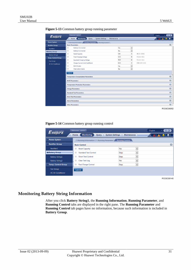
Monitoring Common Battery Information
After you click Battery Group, the Running Information, Running Parameter, and
Running Control tabs are displayed in the right pane.
Figure 5-12 Common battery group running information
SMU02B
User Manual 5 WebUI
Issue 02 (2013-09-09) Huawei Proprietary and Confidential
Copyright © Huawei Technologies Co., Ltd.
31
Figure 5-13 Common battery group running parameter
Figure 5-14 Common battery group running control
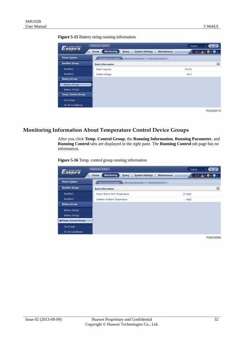
Monitoring Battery String Information
After you click Battery String1, the Running Information, Running Parameter, and
Running Control tabs are displayed in the right pane. The Running Parameter and
Running Control tab pages have no information, because such information is included in
Battery Group.
SMU02B
User Manual 5 WebUI
Issue 02 (2013-09-09) Huawei Proprietary and Confidential
Copyright © Huawei Technologies Co., Ltd.
32
Figure 5-15 Battery string running information
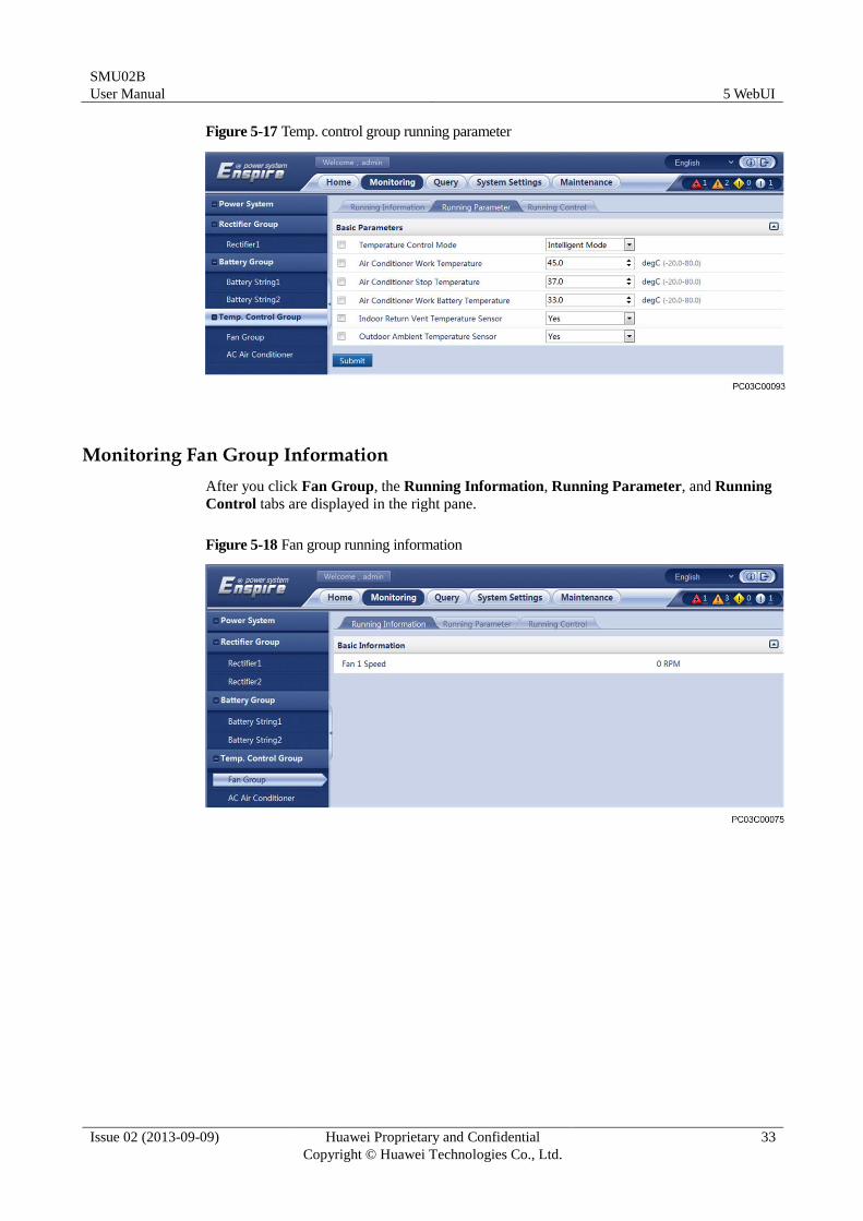
Monitoring Information About Temperature Control Device Groups
After you click Temp. Control Group, the Running Information, Running Parameter, and
Running Control tabs are displayed in the right pane. The Running Control tab page has no
information.
Figure 5-16 Temp. control group running information
SMU02B
User Manual 5 WebUI
Issue 02 (2013-09-09) Huawei Proprietary and Confidential
Copyright © Huawei Technologies Co., Ltd.
33
Figure 5-17 Temp. control group running parameter
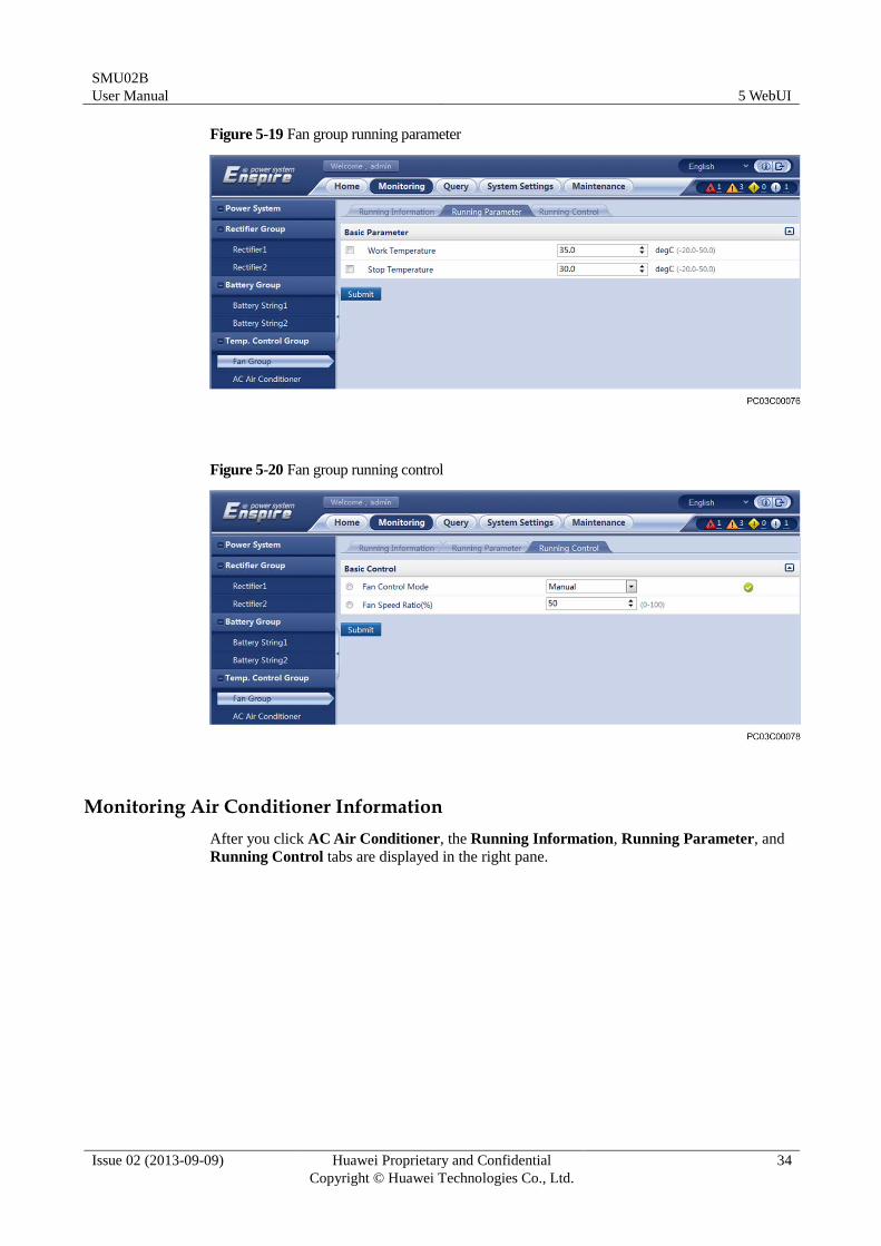
Monitoring Fan Group Information
After you click Fan Group, the Running Information, Running Parameter, and Running
Control tabs are displayed in the right pane.
Figure 5-18 Fan group running information
SMU02B
User Manual 5 WebUI
Issue 02 (2013-09-09) Huawei Proprietary and Confidential
Copyright © Huawei Technologies Co., Ltd.
34
Figure 5-19 Fan group running parameter
Figure 5-20 Fan group running control
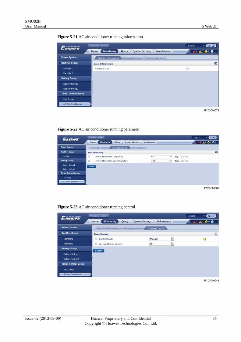
Monitoring Air Conditioner Information
After you click AC Air Conditioner, the Running Information, Running Parameter, and
Running Control tabs are displayed in the right pane.
SMU02B
User Manual 5 WebUI
Issue 02 (2013-09-09) Huawei Proprietary and Confidential
Copyright © Huawei Technologies Co., Ltd.
35
Figure 5-21 AC air conditioner running information
Figure 5-22 AC air conditioner running parameter
Figure 5-23 AC air conditioner running control
SMU02B
User Manual 5 WebUI
Issue 02 (2013-09-09) Huawei Proprietary and Confidential
Copyright © Huawei Technologies Co., Ltd.
36
5.5 Querying Historical Data
The Query tab page allows you to query and export historical alarms, performance data,
operation records, and battery test records.
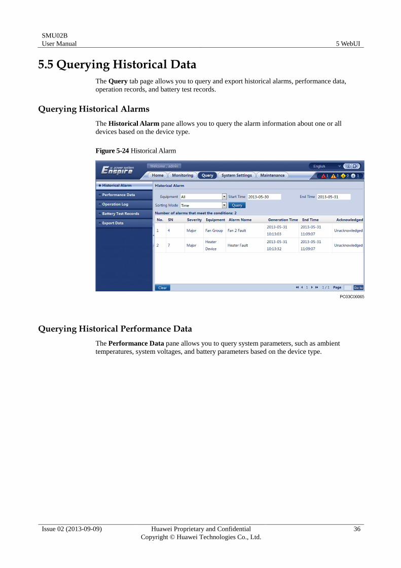
Querying Historical Alarms
The Historical Alarm pane allows you to query the alarm information about one or all
devices based on the device type.
Figure 5-24 Historical Alarm
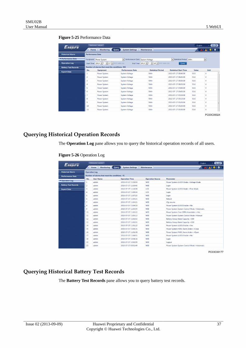
Querying Historical Performance Data
The Performance Data pane allows you to query system parameters, such as ambient
temperatures, system voltages, and battery parameters based on the device type.
SMU02B
User Manual 5 WebUI
Issue 02 (2013-09-09) Huawei Proprietary and Confidential
Copyright © Huawei Technologies Co., Ltd.
37
Figure 5-25 Performance Data
Querying Historical Operation Records
The Operation Log pane allows you to query the historical operation records of all users.
Figure 5-26 Operation Log
Querying Historical Battery Test Records
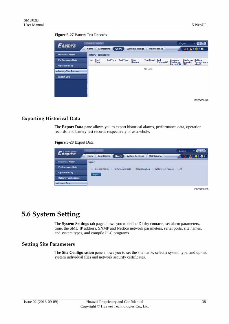
The Battery Test Records pane allows you to query battery test records.
SMU02B
User Manual 5 WebUI
Issue 02 (2013-09-09) Huawei Proprietary and Confidential
Copyright © Huawei Technologies Co., Ltd.
38
Figure 5-27 Battery Test Records
Exporting Historical Data
The Export Data pane allows you to export historical alarms, performance data, operation
records, and battery test records respectively or as a whole.
Figure 5-28 Export Data
5.6 System Setting
The System Settings tab page allows you to define DI dry contacts, set alarm parameters,
time, the SMU IP address, SNMP and NetEco network parameters, serial ports, site names,
and system types, and compile PLC programs.
Setting Site Parameters
The Site Configuration pane allows you to set the site name, select a system type, and upload
system individual files and network security certificates.
SMU02B
User Manual 5 WebUI
Issue 02 (2013-09-09) Huawei Proprietary and Confidential
Copyright © Huawei Technologies Co., Ltd.
39
System individual file: To enable the SMU to be used for a power system that cannot be recognized
by the SMU, you need only to upload a system individual file over the WebUI.
Network security certificate: You can browse SMU WebUIs reliably after uploading network
security certificates.
Figure 5-29 Site Configuration
Setting Time
The Time pane allows you to set a time zone and local time. You can directly set the local
date and time or synchronize the time with that on the Network Time Protocol (NTP) server.
Figure 5-30 Time
Setting an SMU IP Address
The IP Address allows you to set an IP address, a subnet mask, and a default gateway for the
SMU.
SMU02B
User Manual 5 WebUI
Issue 02 (2013-09-09) Huawei Proprietary and Confidential
Copyright © Huawei Technologies Co., Ltd.
40
Figure 5-31 IP Address
Setting SNMP Network Parameters
The SNMP pane allows you to set SNMP network parameters and export Mib files.
Figure 5-32 SNMP
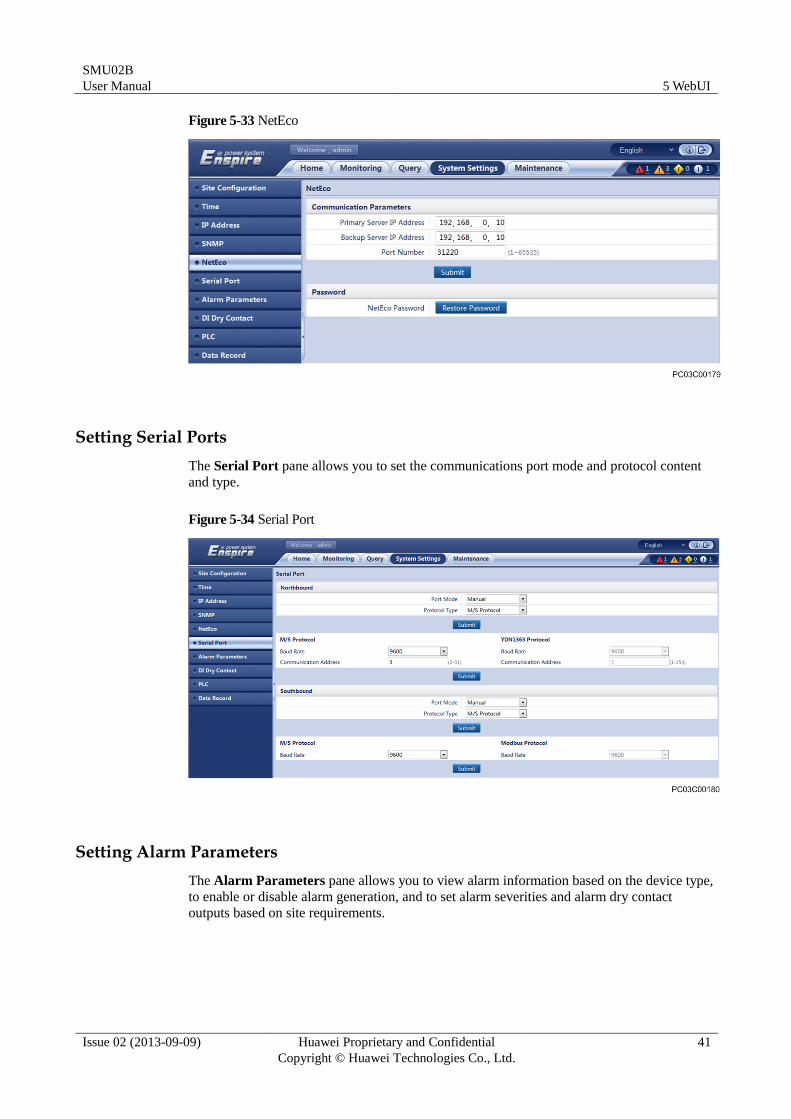
Setting NetEco Network Parameters
The NetEco pane allows you to set NetEco network parameters and restore the NetEco
password.
SMU02B
User Manual 5 WebUI
Issue 02 (2013-09-09) Huawei Proprietary and Confidential
Copyright © Huawei Technologies Co., Ltd.
41
Figure 5-33 NetEco
Setting Serial Ports
The Serial Port pane allows you to set the communications port mode and protocol content
and type.
Figure 5-34 Serial Port
Setting Alarm Parameters
The Alarm Parameters pane allows you to view alarm information based on the device type,
to enable or disable alarm generation, and to set alarm severities and alarm dry contact
outputs based on site requirements.
SMU02B
User Manual 5 WebUI
Issue 02 (2013-09-09) Huawei Proprietary and Confidential
Copyright © Huawei Technologies Co., Ltd.
42
Figure 5-35 Alarm Parameters
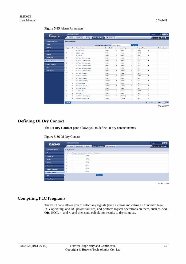
Defining DI Dry Contact
The DI Dry Contact pane allows you to define DI dry contact names.
Figure 5-36 DI Dry Contact
Compiling PLC Programs
The PLC pane allows you to select any signals (such as those indicating DC undervoltage,
D.G. operating, and AC power failures) and perform logical operations on them, such as AND,
OR, NOT, >, and <, and then send calculation results to dry contacts.
SMU02B
User Manual 5 WebUI
Issue 02 (2013-09-09) Huawei Proprietary and Confidential
Copyright © Huawei Technologies Co., Ltd.
43
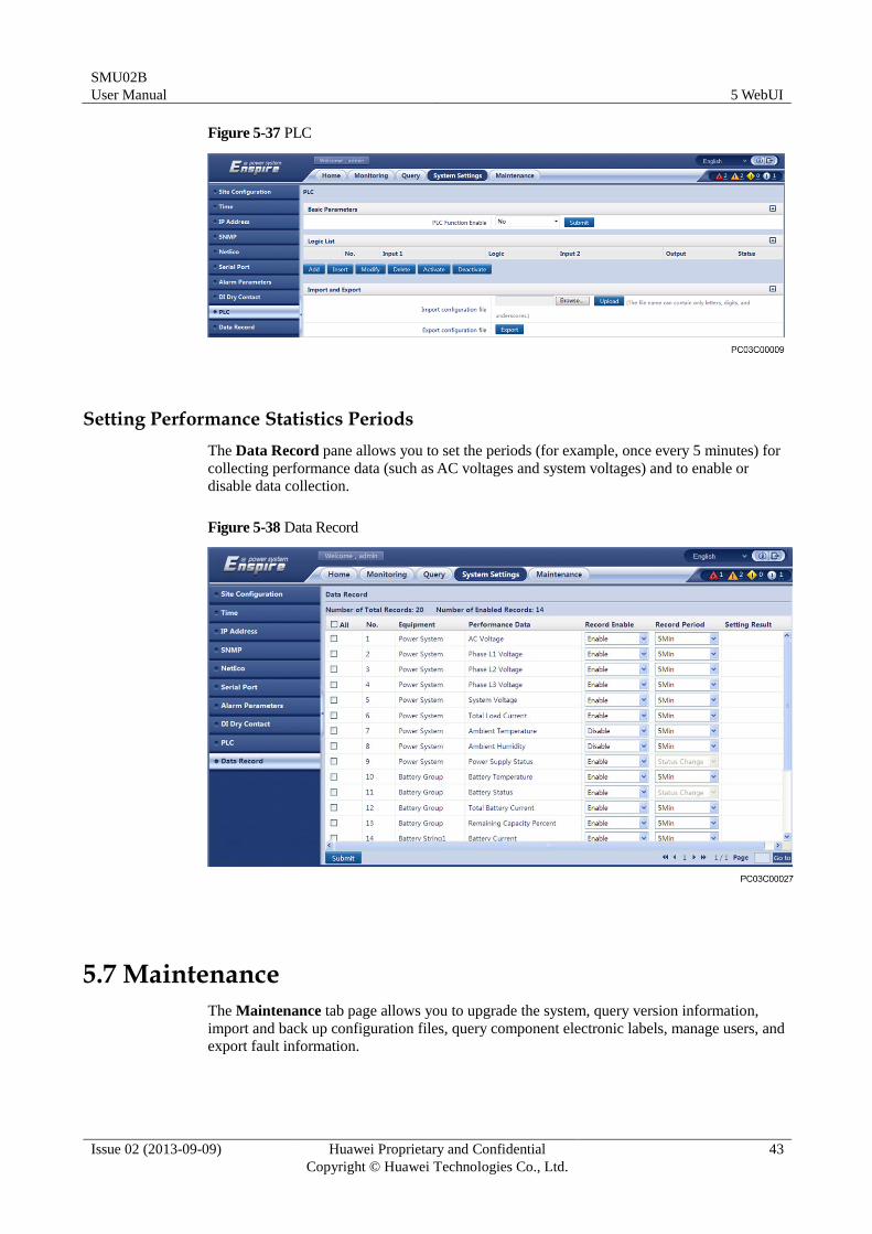
Figure 5-37 PLC
Setting Performance Statistics Periods
The Data Record pane allows you to set the periods (for example, once every 5 minutes) for
collecting performance data (such as AC voltages and system voltages) and to enable or
disable data collection.
Figure 5-38 Data Record
5.7 Maintenance
The Maintenance tab page allows you to upgrade the system, query version information,
import and back up configuration files, query component electronic labels, manage users, and
export fault information.
SMU02B
User Manual 5 WebUI
Issue 02 (2013-09-09) Huawei Proprietary and Confidential
Copyright © Huawei Technologies Co., Ltd.
44
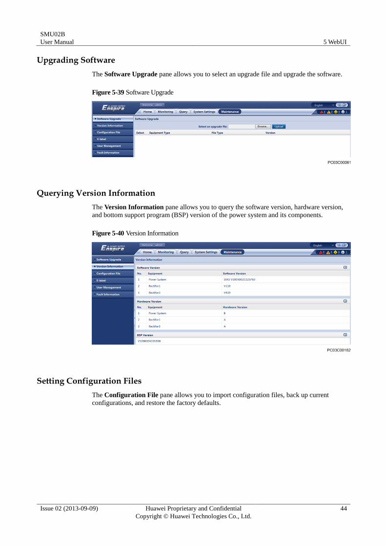
Upgrading Software
The Software Upgrade pane allows you to select an upgrade file and upgrade the software.
Figure 5-39 Software Upgrade
Querying Version Information
The Version Information pane allows you to query the software version, hardware version,
and bottom support program (BSP) version of the power system and its components.
Figure 5-40 Version Information
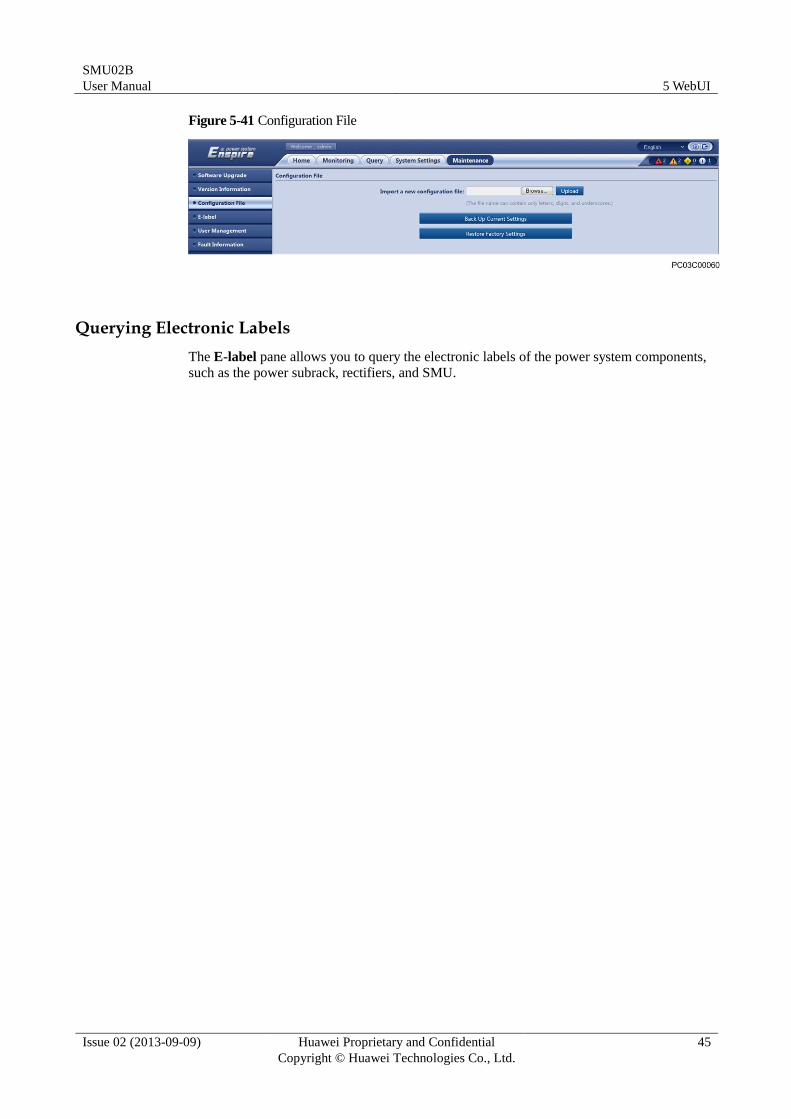
Setting Configuration Files
The Configuration File pane allows you to import configuration files, back up current
configurations, and restore the factory defaults.
SMU02B
User Manual 5 WebUI
Issue 02 (2013-09-09) Huawei Proprietary and Confidential
Copyright © Huawei Technologies Co., Ltd.
45
Figure 5-41 Configuration File
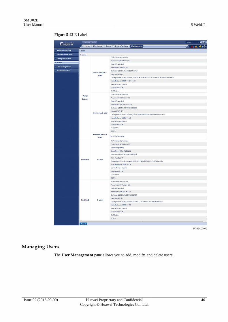
Querying Electronic Labels
The E-label pane allows you to query the electronic labels of the power system components,
such as the power subrack, rectifiers, and SMU.
SMU02B
User Manual 5 WebUI
Issue 02 (2013-09-09) Huawei Proprietary and Confidential
Copyright © Huawei Technologies Co., Ltd.
46
Figure 5-42 E-Label
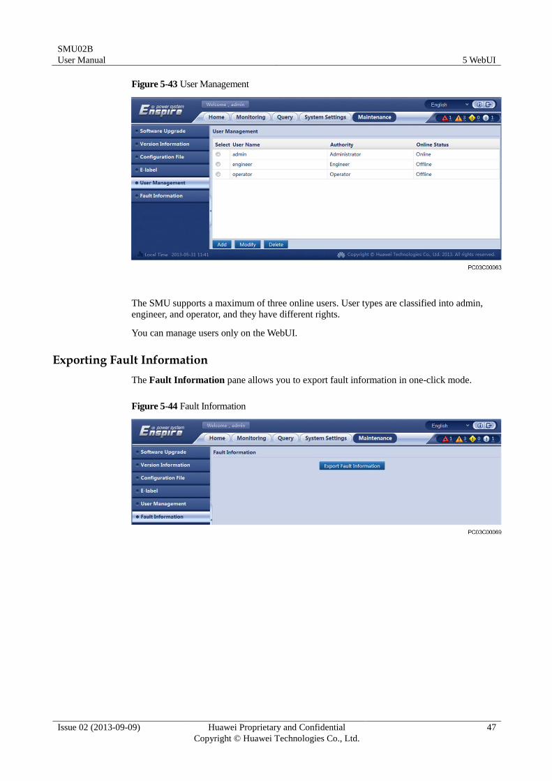
Managing Users
The User Management pane allows you to add, modify, and delete users.
SMU02B
User Manual 5 WebUI
Issue 02 (2013-09-09) Huawei Proprietary and Confidential
Copyright © Huawei Technologies Co., Ltd.
47
Figure 5-43 User Management
The SMU supports a maximum of three online users. User types are classified into admin,
engineer, and operator, and they have different rights.
You can manage users only on the WebUI.
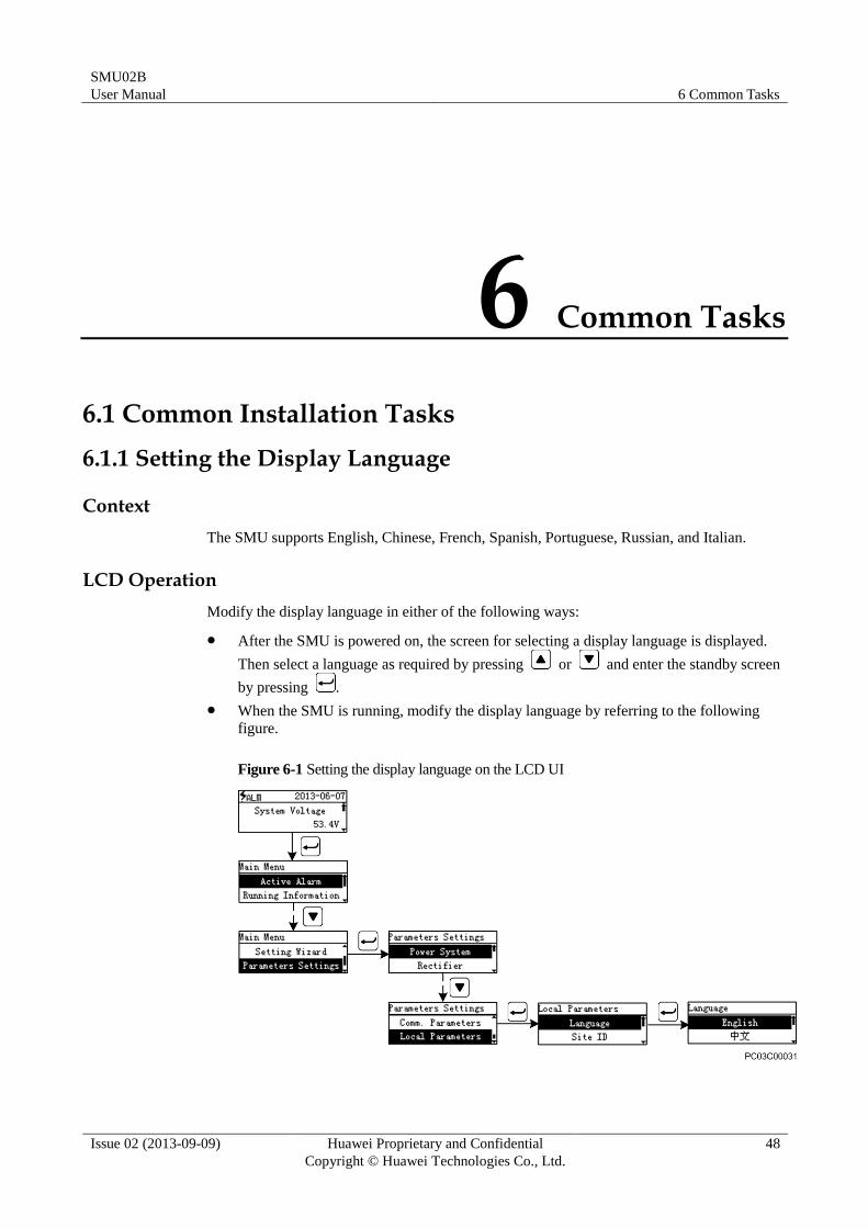
Exporting Fault Information
The Fault Information pane allows you to export fault information in one-click mode.
Figure 5-44 Fault Information
SMU02B
User Manual 6 Common Tasks
Issue 02 (2013-09-09) Huawei Proprietary and Confidential
Copyright © Huawei Technologies Co., Ltd.
48
6 Common Tasks
6.1 Common Installation Tasks
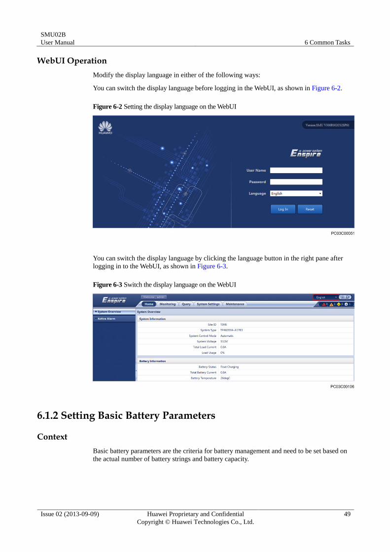
6.1.1 Setting the Display Language
Context
The SMU supports English, Chinese, French, Spanish, Portuguese, Russian, and Italian.
LCD Operation
Modify the display language in either of the following ways:
After the SMU is powered on, the screen for selecting a display language is displayed.
Then select a language as required by pressing or and enter the standby screen
by pressing .
When the SMU is running, modify the display language by referring to the following
figure.
Figure 6-1 Setting the display language on the LCD UI
SMU02B
User Manual 6 Common Tasks
Issue 02 (2013-09-09) Huawei Proprietary and Confidential
Copyright © Huawei Technologies Co., Ltd.
49
WebUI Operation
Modify the display language in either of the following ways:
You can switch the display language before logging in the WebUI, as shown in Figure 6-2.
Figure 6-2 Setting the display language on the WebUI
You can switch the display language by clicking the language button in the right pane after
logging in to the WebUI, as shown in Figure 6-3.
Figure 6-3 Switch the display language on the WebUI
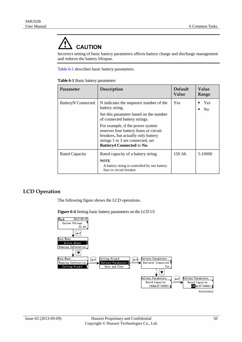
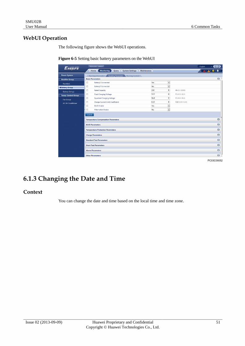
6.1.2 Setting Basic Battery Parameters
Context
Basic battery parameters are the criteria for battery management and need to be set based on
the actual number of battery strings and battery capacity.
SMU02B
User Manual 6 Common Tasks
Issue 02 (2013-09-09) Huawei Proprietary and Confidential
Copyright © Huawei Technologies Co., Ltd.
50
Incorrect setting of basic battery parameters affects battery charge and discharge management
and reduces the battery lifespan.
Table 6-1 describes basic battery parameters.
Table 6-1 Basic battery parameters
Parameter Description Default Value
Value Range
BatteryN Connected N indicates the sequence number of the
battery string.
Set this parameter based on the number
of connected battery strings.
For example, if the power system
reserves four battery fuses or circuit
breakers, but actually only battery
strings 1 to 3 are connected, set
Battery4 Connected to No.
Yes Yes
No
Rated Capacity Rated capacity of a battery string.
NOTE
A battery string is controlled by one battery
fuse or circuit breaker.
150 Ah 5-10000
LCD Operation
The following figure shows the LCD operations.
Figure 6-4 Setting basic battery parameters on the LCD UI
SMU02B
User Manual 6 Common Tasks
Issue 02 (2013-09-09) Huawei Proprietary and Confidential
Copyright © Huawei Technologies Co., Ltd.
51
WebUI Operation
The following figure shows the WebUI operations.
Figure 6-5 Setting basic battery parameters on the WebUI
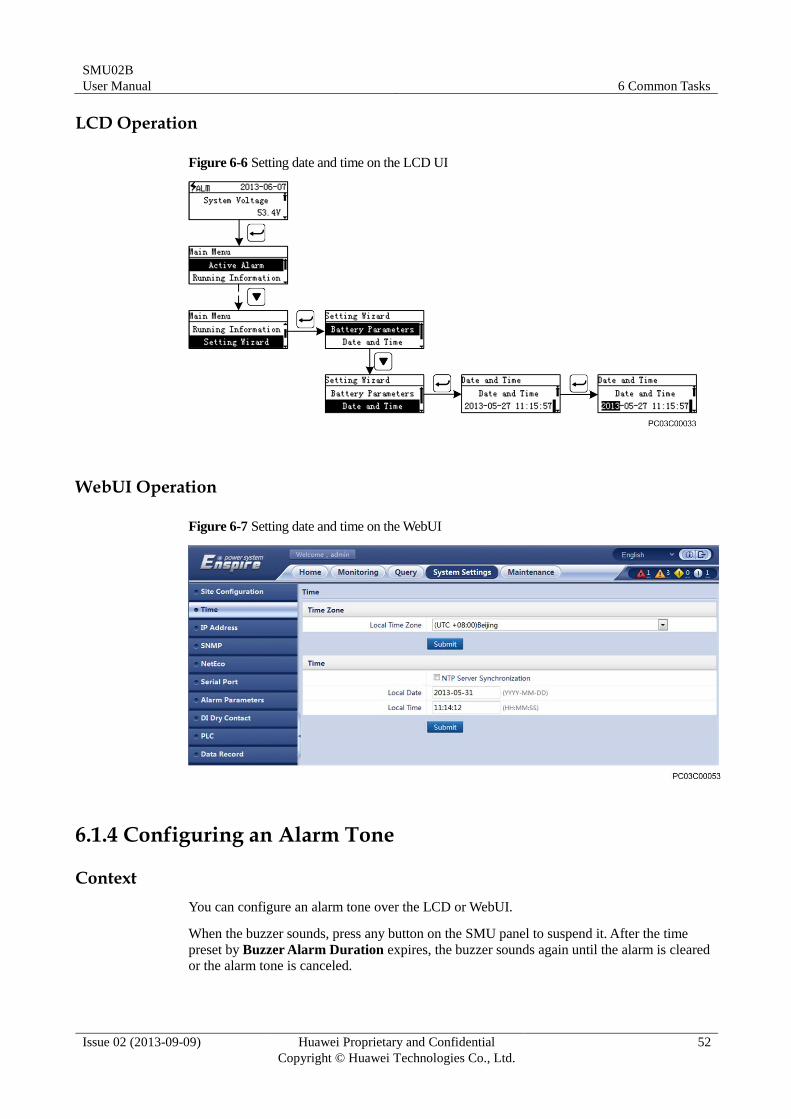
6.1.3 Changing the Date and Time
Context
You can change the date and time based on the local time and time zone.
SMU02B
User Manual 6 Common Tasks
Issue 02 (2013-09-09) Huawei Proprietary and Confidential
Copyright © Huawei Technologies Co., Ltd.
52
LCD Operation
Figure 6-6 Setting date and time on the LCD UI
WebUI Operation
Figure 6-7 Setting date and time on the WebUI
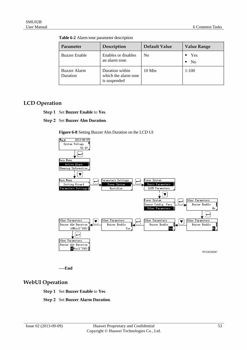
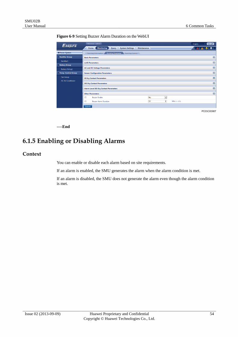
6.1.4 Configuring an Alarm Tone
Context
You can configure an alarm tone over the LCD or WebUI.
When the buzzer sounds, press any button on the SMU panel to suspend it. After the time
preset by Buzzer Alarm Duration expires, the buzzer sounds again until the alarm is cleared
or the alarm tone is canceled.
SMU02B
User Manual 6 Common Tasks
Issue 02 (2013-09-09) Huawei Proprietary and Confidential
Copyright © Huawei Technologies Co., Ltd.
53
Table 6-2 Alarm tone parameter description
Parameter Description Default Value Value Range
Buzzer Enable Enables or disables
an alarm tone.
No Yes
No
Buzzer Alarm
Duration
Duration within
which the alarm tone
is suspended
10 Min 1-100
LCD Operation
Step 1 Set Buzzer Enable to Yes.
Step 2 Set Buzzer Alm Duration.
Figure 6-8 Setting Buzzer Alm Duration on the LCD UI
----End
WebUI Operation
Step 1 Set Buzzer Enable to Yes.
Step 2 Set Buzzer Alarm Duration.
SMU02B
User Manual 6 Common Tasks
Issue 02 (2013-09-09) Huawei Proprietary and Confidential
Copyright © Huawei Technologies Co., Ltd.
54
Figure 6-9 Setting Buzzer Alarm Duration on the WebUI
----End
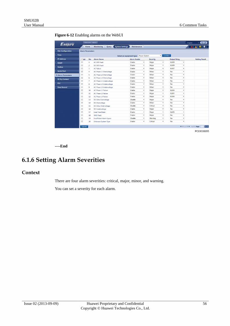
6.1.5 Enabling or Disabling Alarms
Context
You can enable or disable each alarm based on site requirements.
If an alarm is enabled, the SMU generates the alarm when the alarm condition is met.
If an alarm is disabled, the SMU does not generate the alarm even though the alarm condition
is met.
SMU02B
User Manual 6 Common Tasks
Issue 02 (2013-09-09) Huawei Proprietary and Confidential
Copyright © Huawei Technologies Co., Ltd.
55
LCD Operation
Figure 6-10 Enabling alarms on the LCD UI
WebUI Operation
Step 1 Select an equipment type.
Figure 6-11 Selecting an equipment type on the WebUI
Step 2 Enable alarms on the alarm list corresponding to Power System.
SMU02B
User Manual 6 Common Tasks
Issue 02 (2013-09-09) Huawei Proprietary and Confidential
Copyright © Huawei Technologies Co., Ltd.
56
Figure 6-12 Enabling alarms on the WebUI
----End
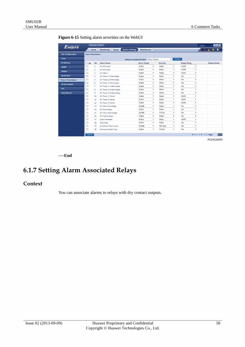
6.1.6 Setting Alarm Severities
Context
There are four alarm severities: critical, major, minor, and warning.
You can set a severity for each alarm.

SMU02B
User Manual 6 Common Tasks
Issue 02 (2013-09-09) Huawei Proprietary and Confidential
Copyright © Huawei Technologies Co., Ltd.
57
LCD Operation
Figure 6-13 Setting alarm severities on the LCD UI
WebUI Operation
Step 1 Select an equipment type.
Figure 6-14 Selecting an equipment type on the WebUI
Step 2 Set severities for the alarms on the alarm list corresponding to Power System.
SMU02B
User Manual 6 Common Tasks
Issue 02 (2013-09-09) Huawei Proprietary and Confidential
Copyright © Huawei Technologies Co., Ltd.
58
Figure 6-15 Setting alarm severities on the WebUI
----End
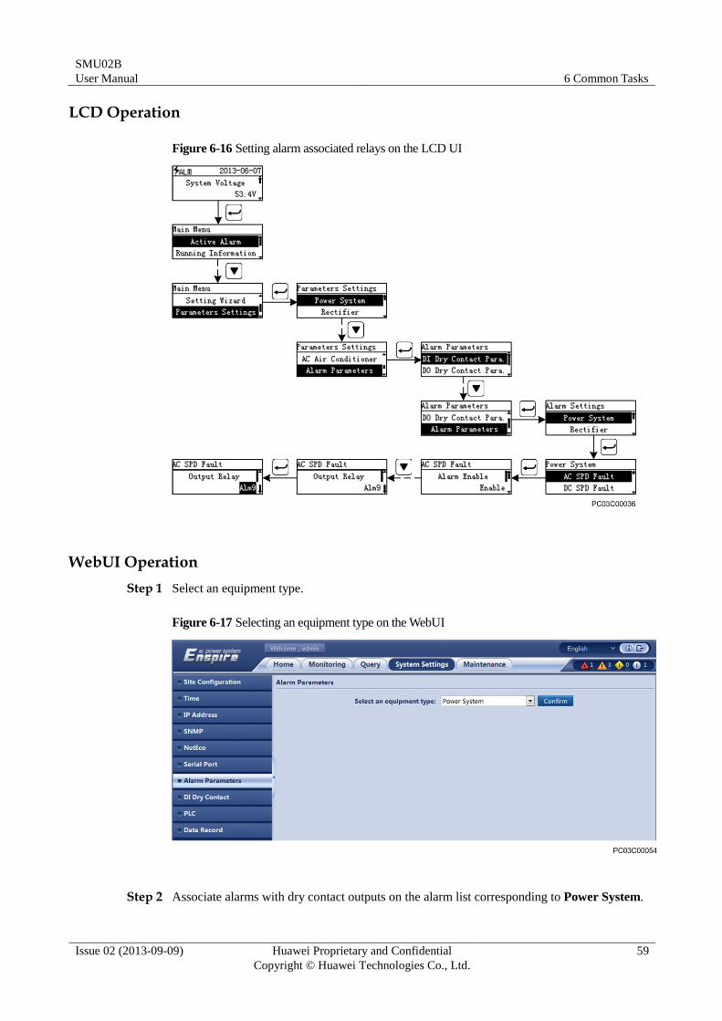
6.1.7 Setting Alarm Associated Relays
Context
You can associate alarms to relays with dry contact outputs.
SMU02B
User Manual 6 Common Tasks
Issue 02 (2013-09-09) Huawei Proprietary and Confidential
Copyright © Huawei Technologies Co., Ltd.
59
LCD Operation
Figure 6-16 Setting alarm associated relays on the LCD UI
WebUI Operation
Step 1 Select an equipment type.
Figure 6-17 Selecting an equipment type on the WebUI
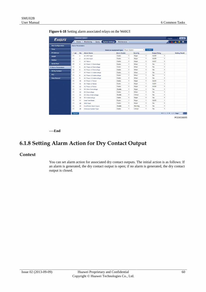
Step 2 Associate alarms with dry contact outputs on the alarm list corresponding to Power System.
SMU02B
User Manual 6 Common Tasks
Issue 02 (2013-09-09) Huawei Proprietary and Confidential
Copyright © Huawei Technologies Co., Ltd.
60
Figure 6-18 Setting alarm associated relays on the WebUI
----End
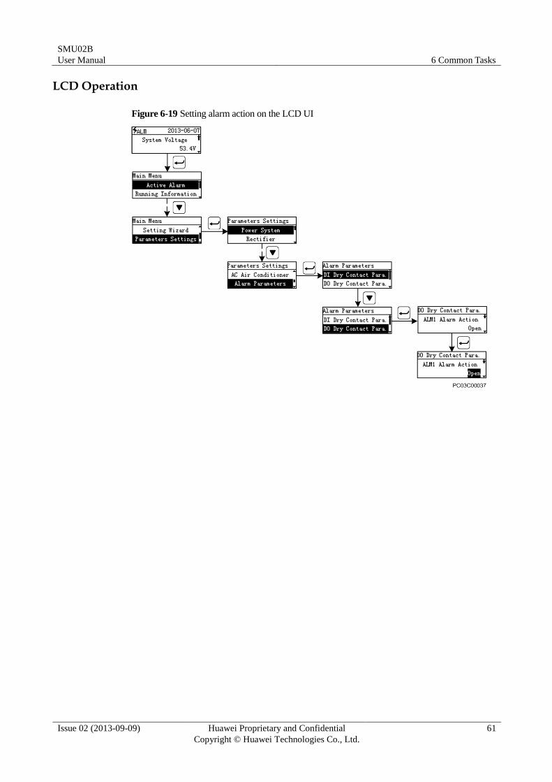
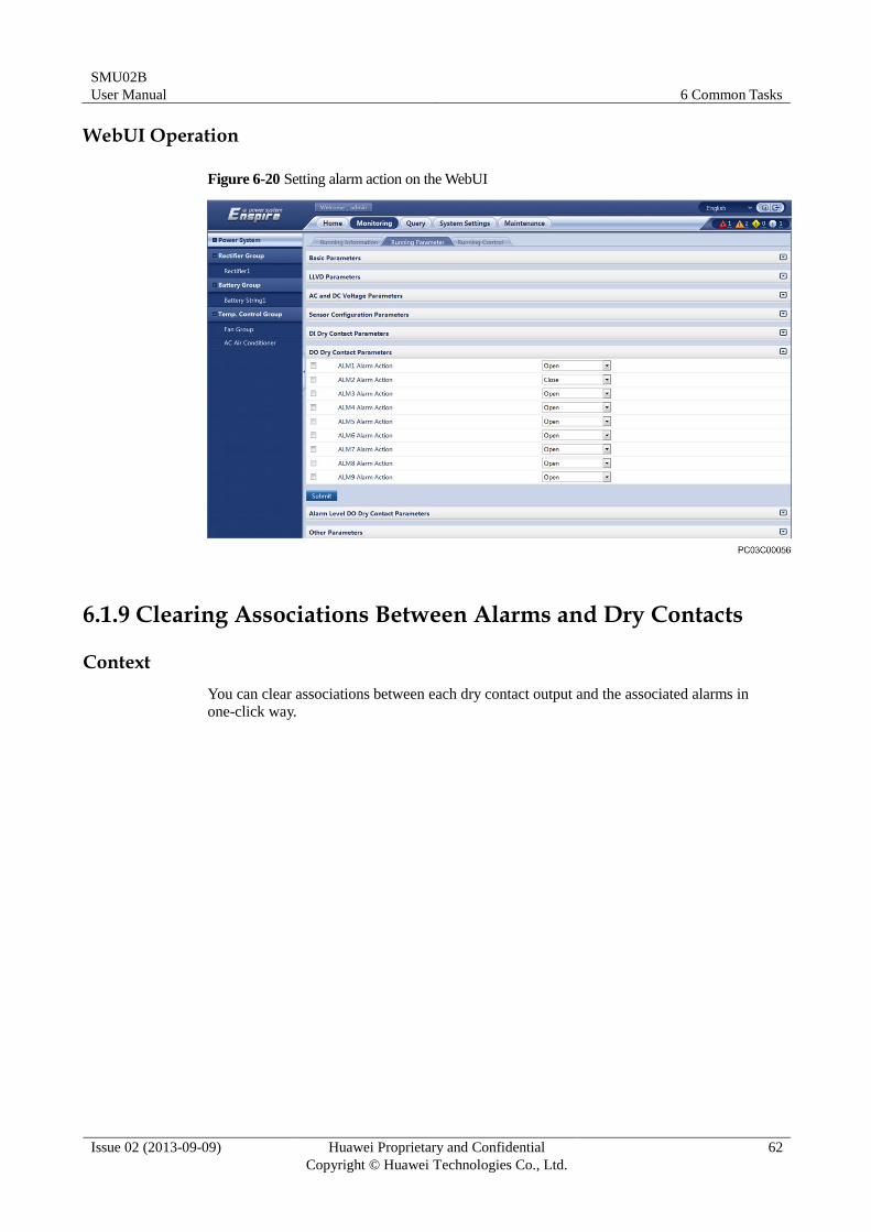
6.1.8 Setting Alarm Action for Dry Contact Output
Context
You can set alarm action for associated dry contact outputs. The initial action is as follows: If
an alarm is generated, the dry contact output is open; if no alarm is generated, the dry contact
output is closed.
SMU02B
User Manual 6 Common Tasks
Issue 02 (2013-09-09) Huawei Proprietary and Confidential
Copyright © Huawei Technologies Co., Ltd.
61
LCD Operation
Figure 6-19 Setting alarm action on the LCD UI
SMU02B
User Manual 6 Common Tasks
Issue 02 (2013-09-09) Huawei Proprietary and Confidential
Copyright © Huawei Technologies Co., Ltd.
62
WebUI Operation
Figure 6-20 Setting alarm action on the WebUI
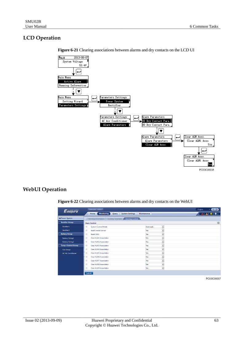
6.1.9 Clearing Associations Between Alarms and Dry Contacts
Context
You can clear associations between each dry contact output and the associated alarms in
one-click way.
SMU02B
User Manual 6 Common Tasks
Issue 02 (2013-09-09) Huawei Proprietary and Confidential
Copyright © Huawei Technologies Co., Ltd.
63
LCD Operation
Figure 6-21 Clearing associations between alarms and dry contacts on the LCD UI
WebUI Operation
Figure 6-22 Clearing associations between alarms and dry contacts on the WebUI
SMU02B
User Manual 6 Common Tasks
Issue 02 (2013-09-09) Huawei Proprietary and Confidential
Copyright © Huawei Technologies Co., Ltd.
64
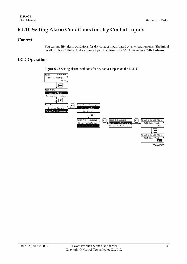
6.1.10 Setting Alarm Conditions for Dry Contact Inputs
Context
You can modify alarm conditions for dry contact inputs based on site requirements. The initial
condition is as follows: If dry contact input 1 is closed, the SMU generates a DIN1 Alarm.
LCD Operation
Figure 6-23 Setting alarm conditions for dry contact inputs on the LCD UI
SMU02B
User Manual 6 Common Tasks
Issue 02 (2013-09-09) Huawei Proprietary and Confidential
Copyright © Huawei Technologies Co., Ltd.
65
WebUI Operation
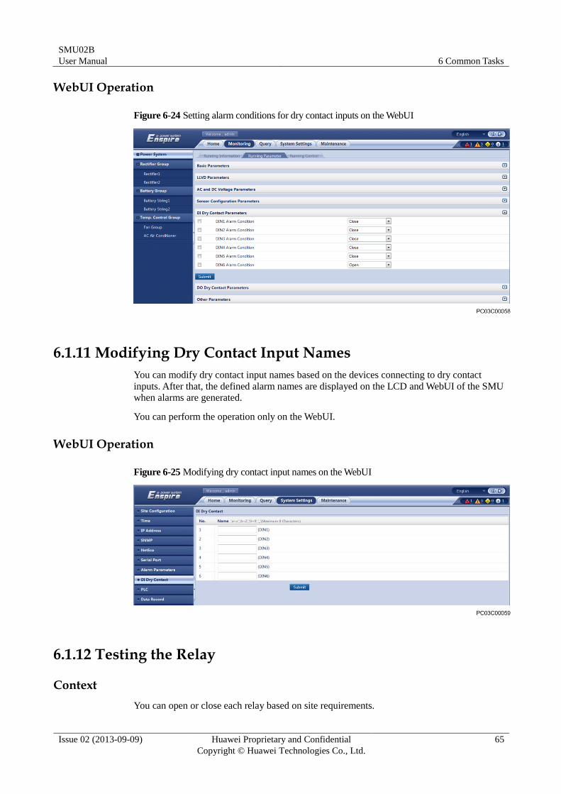
Figure 6-24 Setting alarm conditions for dry contact inputs on the WebUI
6.1.11 Modifying Dry Contact Input Names
You can modify dry contact input names based on the devices connecting to dry contact
inputs. After that, the defined alarm names are displayed on the LCD and WebUI of the SMU
when alarms are generated.
You can perform the operation only on the WebUI.
WebUI Operation
Figure 6-25 Modifying dry contact input names on the WebUI
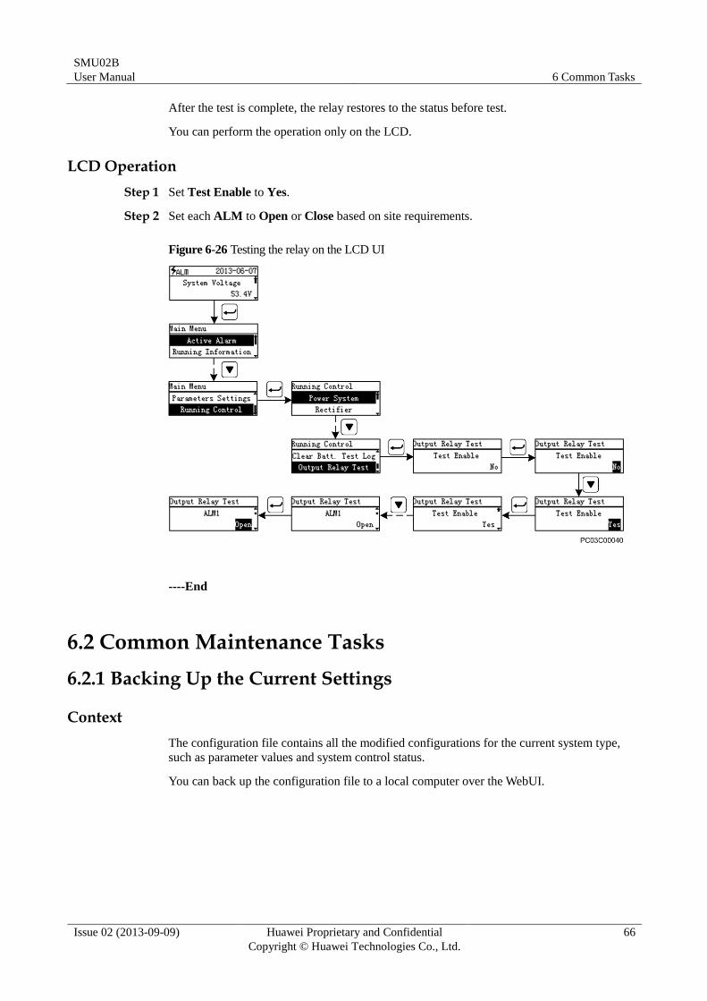
6.1.12 Testing the Relay
Context
You can open or close each relay based on site requirements.
SMU02B
User Manual 6 Common Tasks
Issue 02 (2013-09-09) Huawei Proprietary and Confidential
Copyright © Huawei Technologies Co., Ltd.
66
After the test is complete, the relay restores to the status before test.
You can perform the operation only on the LCD.
LCD Operation
Step 1 Set Test Enable to Yes.
Step 2 Set each ALM to Open or Close based on site requirements.
Figure 6-26 Testing the relay on the LCD UI
----End
6.2 Common Maintenance Tasks
6.2.1 Backing Up the Current Settings
Context
The configuration file contains all the modified configurations for the current system type,
such as parameter values and system control status.
You can back up the configuration file to a local computer over the WebUI.
SMU02B
User Manual 6 Common Tasks
Issue 02 (2013-09-09) Huawei Proprietary and Confidential
Copyright © Huawei Technologies Co., Ltd.
67
WebUI Operation
Figure 6-27 Backing up the current configuration file on the WebUI
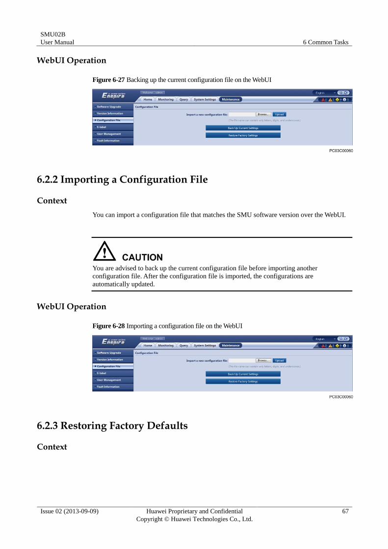
6.2.2 Importing a Configuration File
Context
You can import a configuration file that matches the SMU software version over the WebUI.
You are advised to back up the current configuration file before importing another
configuration file. After the configuration file is imported, the configurations are
automatically updated.
WebUI Operation
Figure 6-28 Importing a configuration file on the WebUI
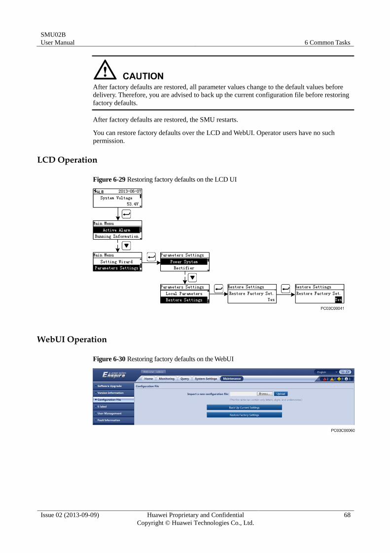
6.2.3 Restoring Factory Defaults
Context
SMU02B
User Manual 6 Common Tasks
Issue 02 (2013-09-09) Huawei Proprietary and Confidential
Copyright © Huawei Technologies Co., Ltd.
68
After factory defaults are restored, all parameter values change to the default values before
delivery. Therefore, you are advised to back up the current configuration file before restoring
factory defaults.
After factory defaults are restored, the SMU restarts.
You can restore factory defaults over the LCD and WebUI. Operator users have no such
permission.
LCD Operation
Figure 6-29 Restoring factory defaults on the LCD UI
WebUI Operation
Figure 6-30 Restoring factory defaults on the WebUI
SMU02B
User Manual 6 Common Tasks
Issue 02 (2013-09-09) Huawei Proprietary and Confidential
Copyright © Huawei Technologies Co., Ltd.
69
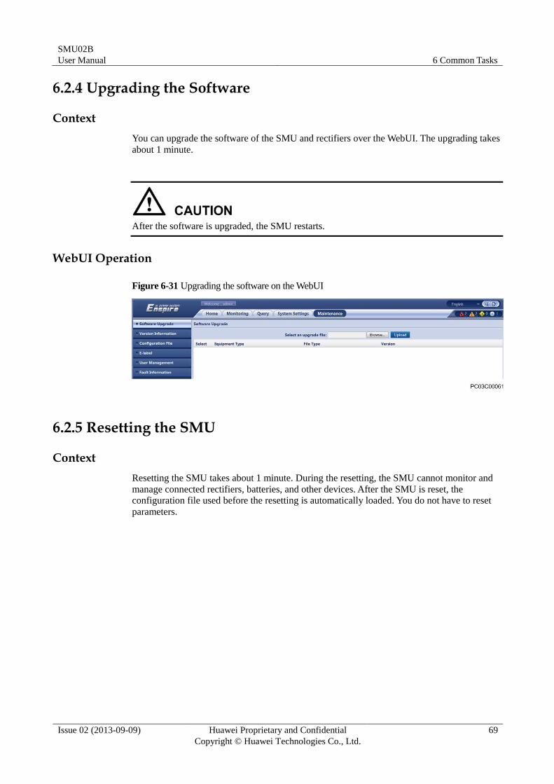
6.2.4 Upgrading the Software
Context
You can upgrade the software of the SMU and rectifiers over the WebUI. The upgrading takes
about 1 minute.
After the software is upgraded, the SMU restarts.
WebUI Operation
Figure 6-31 Upgrading the software on the WebUI
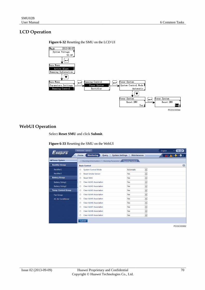
6.2.5 Resetting the SMU
Context
Resetting the SMU takes about 1 minute. During the resetting, the SMU cannot monitor and
manage connected rectifiers, batteries, and other devices. After the SMU is reset, the
configuration file used before the resetting is automatically loaded. You do not have to reset
parameters.
SMU02B
User Manual 6 Common Tasks
Issue 02 (2013-09-09) Huawei Proprietary and Confidential
Copyright © Huawei Technologies Co., Ltd.
70
LCD Operation
Figure 6-32 Resetting the SMU on the LCD UI
WebUI Operation
Select Reset SMU and click Submit.
Figure 6-33 Resetting the SMU on the WebUI
SMU02B
User Manual 6 Common Tasks
Issue 02 (2013-09-09) Huawei Proprietary and Confidential
Copyright © Huawei Technologies Co., Ltd.
71
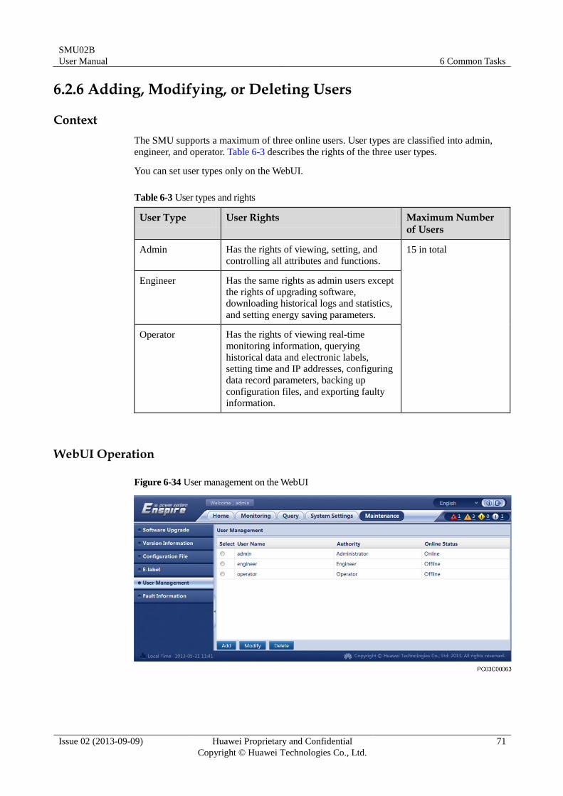
6.2.6 Adding, Modifying, or Deleting Users
Context
The SMU supports a maximum of three online users. User types are classified into admin,
engineer, and operator. Table 6-3 describes the rights of the three user types.
You can set user types only on the WebUI.
Table 6-3 User types and rights
User Type User Rights Maximum Number of Users
Admin Has the rights of viewing, setting, and
controlling all attributes and functions.
15 in total
Engineer Has the same rights as admin users except
the rights of upgrading software,
downloading historical logs and statistics,
and setting energy saving parameters.
Operator Has the rights of viewing real-time
monitoring information, querying
historical data and electronic labels,
setting time and IP addresses, configuring
data record parameters, backing up
configuration files, and exporting faulty
information.
WebUI Operation
Figure 6-34 User management on the WebUI
SMU02B
User Manual 6 Common Tasks
Issue 02 (2013-09-09) Huawei Proprietary and Confidential
Copyright © Huawei Technologies Co., Ltd.
72
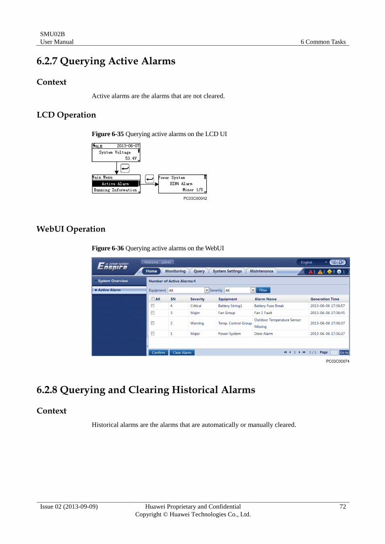
6.2.7 Querying Active Alarms
Context
Active alarms are the alarms that are not cleared.
LCD Operation
Figure 6-35 Querying active alarms on the LCD UI
WebUI Operation
Figure 6-36 Querying active alarms on the WebUI
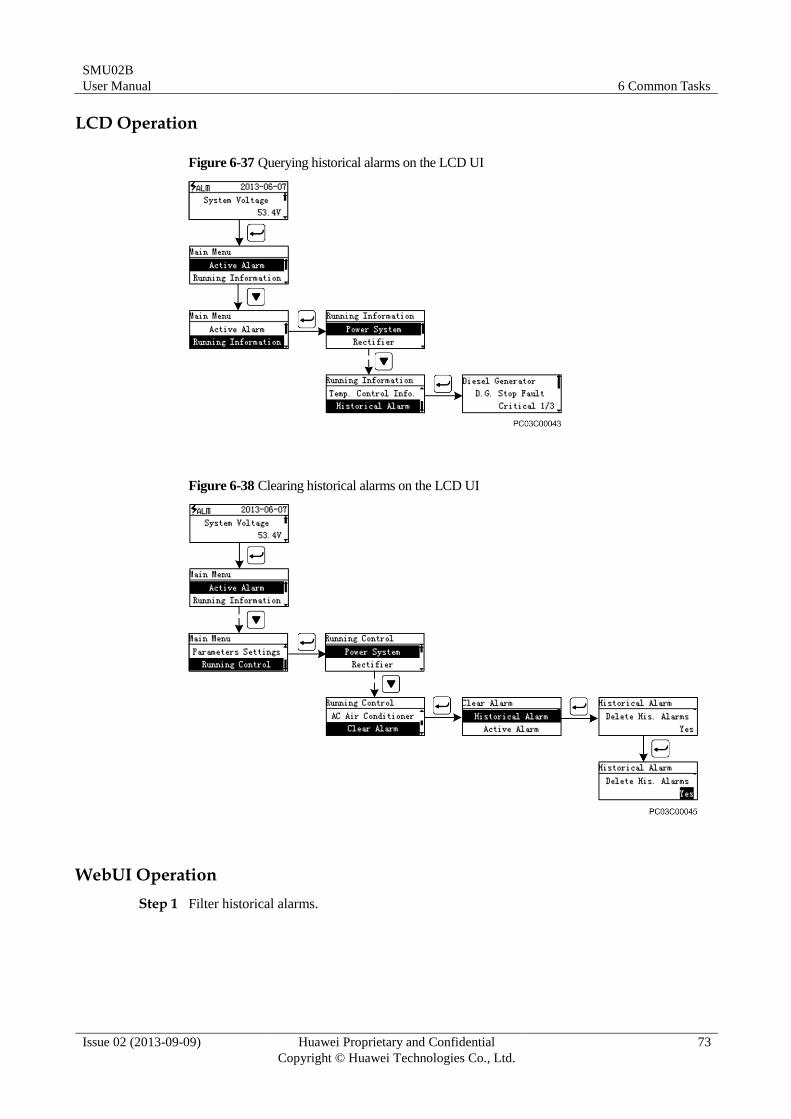
6.2.8 Querying and Clearing Historical Alarms
Context
Historical alarms are the alarms that are automatically or manually cleared.
SMU02B
User Manual 6 Common Tasks
Issue 02 (2013-09-09) Huawei Proprietary and Confidential
Copyright © Huawei Technologies Co., Ltd.
73
LCD Operation
Figure 6-37 Querying historical alarms on the LCD UI
Figure 6-38 Clearing historical alarms on the LCD UI
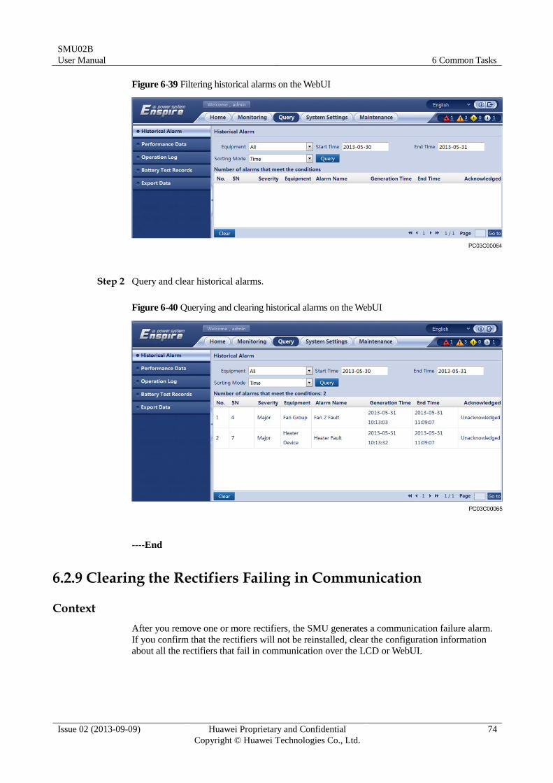
WebUI Operation
Step 1 Filter historical alarms.
SMU02B
User Manual 6 Common Tasks
Issue 02 (2013-09-09) Huawei Proprietary and Confidential
Copyright © Huawei Technologies Co., Ltd.
74
Figure 6-39 Filtering historical alarms on the WebUI
Step 2 Query and clear historical alarms.
Figure 6-40 Querying and clearing historical alarms on the WebUI
----End
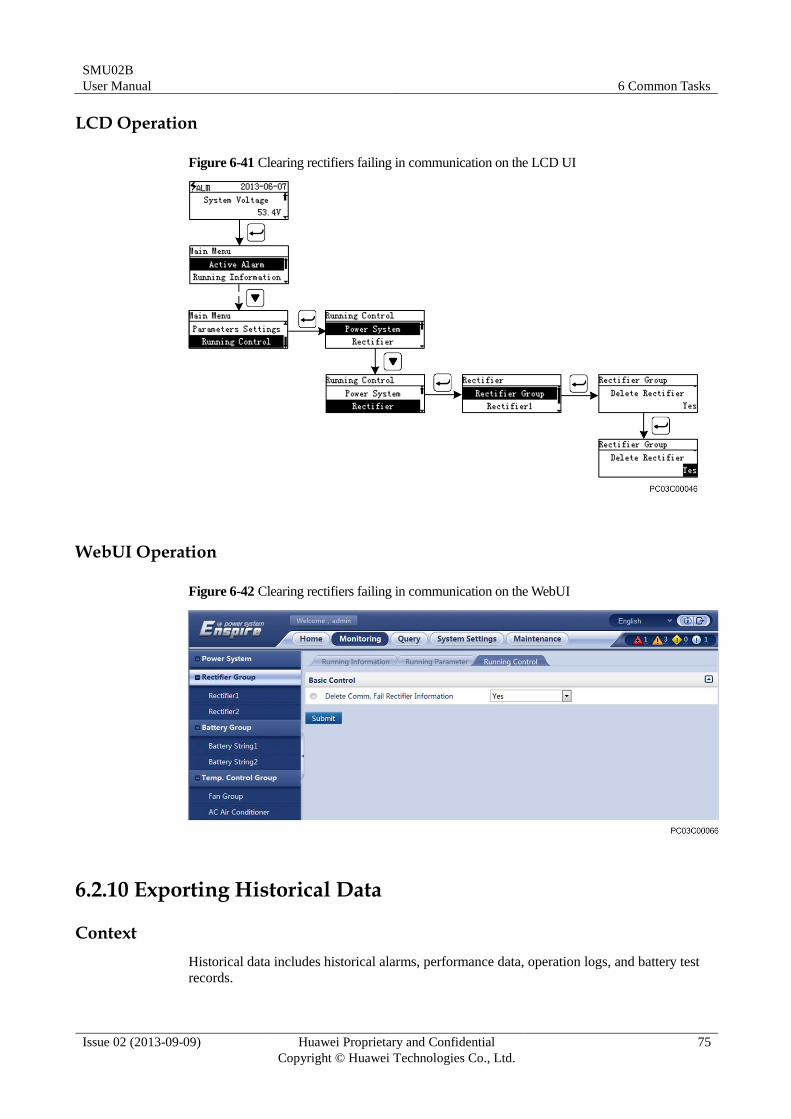
6.2.9 Clearing the Rectifiers Failing in Communication
Context
After you remove one or more rectifiers, the SMU generates a communication failure alarm.
If you confirm that the rectifiers will not be reinstalled, clear the configuration information
about all the rectifiers that fail in communication over the LCD or WebUI.
SMU02B
User Manual 6 Common Tasks
Issue 02 (2013-09-09) Huawei Proprietary and Confidential
Copyright © Huawei Technologies Co., Ltd.
75
LCD Operation
Figure 6-41 Clearing rectifiers failing in communication on the LCD UI
WebUI Operation
Figure 6-42 Clearing rectifiers failing in communication on the WebUI
6.2.10 Exporting Historical Data
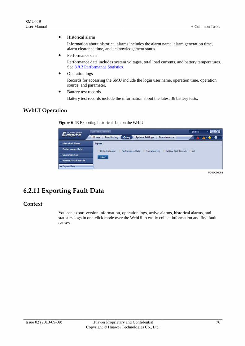
Context
Historical data includes historical alarms, performance data, operation logs, and battery test
records.
SMU02B
User Manual 6 Common Tasks
Issue 02 (2013-09-09) Huawei Proprietary and Confidential
Copyright © Huawei Technologies Co., Ltd.
76
Historical alarm
Information about historical alarms includes the alarm name, alarm generation time,
alarm clearance time, and acknowledgement status.
Performance data
Performance data includes system voltages, total load currents, and battery temperatures.
See 8.8.2 Performance Statistics.
Operation logs
Records for accessing the SMU include the login user name, operation time, operation
source, and parameter.
Battery test records
Battery test records include the information about the latest 36 battery tests.
WebUI Operation
Figure 6-43 Exporting historical data on the WebUI
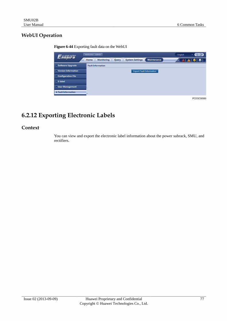
6.2.11 Exporting Fault Data
Context
You can export version information, operation logs, active alarms, historical alarms, and
statistics logs in one-click mode over the WebUI to easily collect information and find fault
causes.
SMU02B
User Manual 6 Common Tasks
Issue 02 (2013-09-09) Huawei Proprietary and Confidential
Copyright © Huawei Technologies Co., Ltd.
77
WebUI Operation
Figure 6-44 Exporting fault data on the WebUI
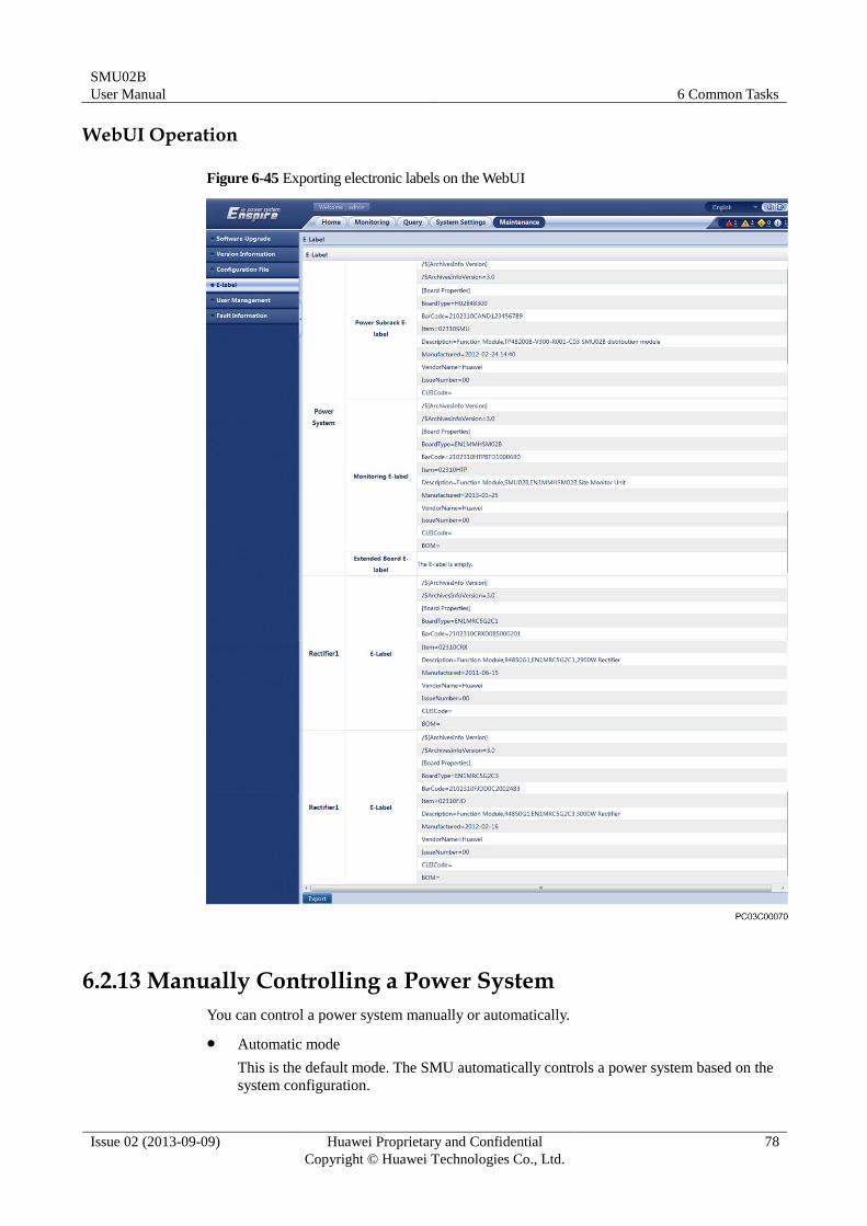
6.2.12 Exporting Electronic Labels
Context
You can view and export the electronic label information about the power subrack, SMU, and
rectifiers.
SMU02B
User Manual 6 Common Tasks
Issue 02 (2013-09-09) Huawei Proprietary and Confidential
Copyright © Huawei Technologies Co., Ltd.
78
WebUI Operation
Figure 6-45 Exporting electronic labels on the WebUI
6.2.13 Manually Controlling a Power System
You can control a power system manually or automatically.
Automatic mode
This is the default mode. The SMU automatically controls a power system based on the
system configuration.
SMU02B
User Manual 6 Common Tasks
Issue 02 (2013-09-09) Huawei Proprietary and Confidential
Copyright © Huawei Technologies Co., Ltd.
79
Manual mode
You manually control a power system over the SMU, such as converting between
equalized charging and float charging, connecting or disconnecting batteries, powering
on/off loads, and starting or shutting down rectifiers. The manual mode is restored to the
automatic mode after the preset time expires.
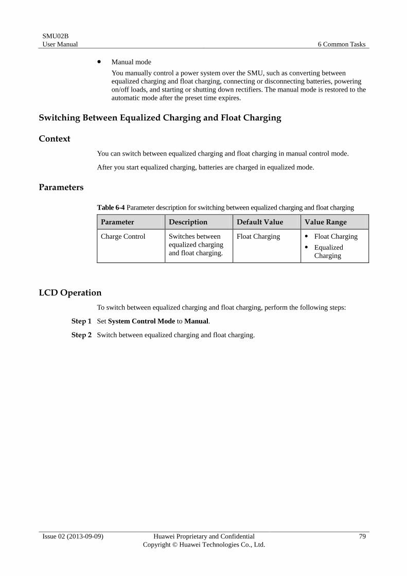
Switching Between Equalized Charging and Float Charging
Context
You can switch between equalized charging and float charging in manual control mode.
After you start equalized charging, batteries are charged in equalized mode.
Parameters
Table 6-4 Parameter description for switching between equalized charging and float charging
Parameter Description Default Value Value Range
Charge Control Switches between
equalized charging
and float charging.
Float Charging Float Charging
Equalized
Charging
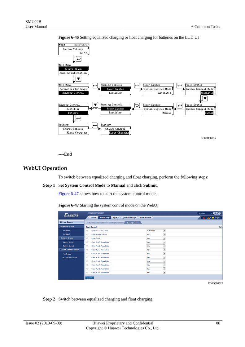
LCD Operation
To switch between equalized charging and float charging, perform the following steps:
Step 1 Set System Control Mode to Manual.
Step 2 Switch between equalized charging and float charging.
SMU02B
User Manual 6 Common Tasks
Issue 02 (2013-09-09) Huawei Proprietary and Confidential
Copyright © Huawei Technologies Co., Ltd.
80
Figure 6-46 Setting equalized charging or float charging for batteries on the LCD UI
----End
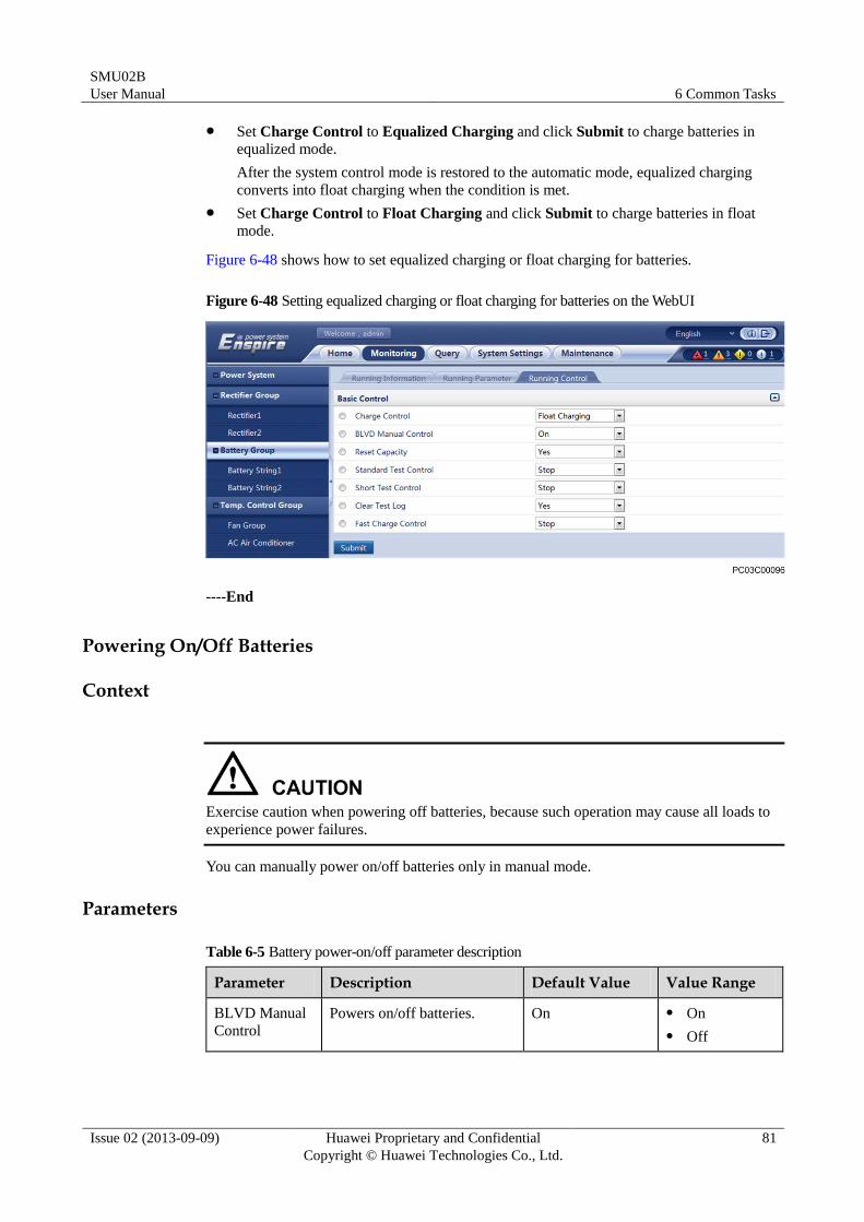
WebUI Operation
To switch between equalized charging and float charging, perform the following steps:
Step 1 Set System Control Mode to Manual and click Submit.
Figure 6-47 shows how to start the system control mode.
Figure 6-47 Starting the system control mode on the WebUI
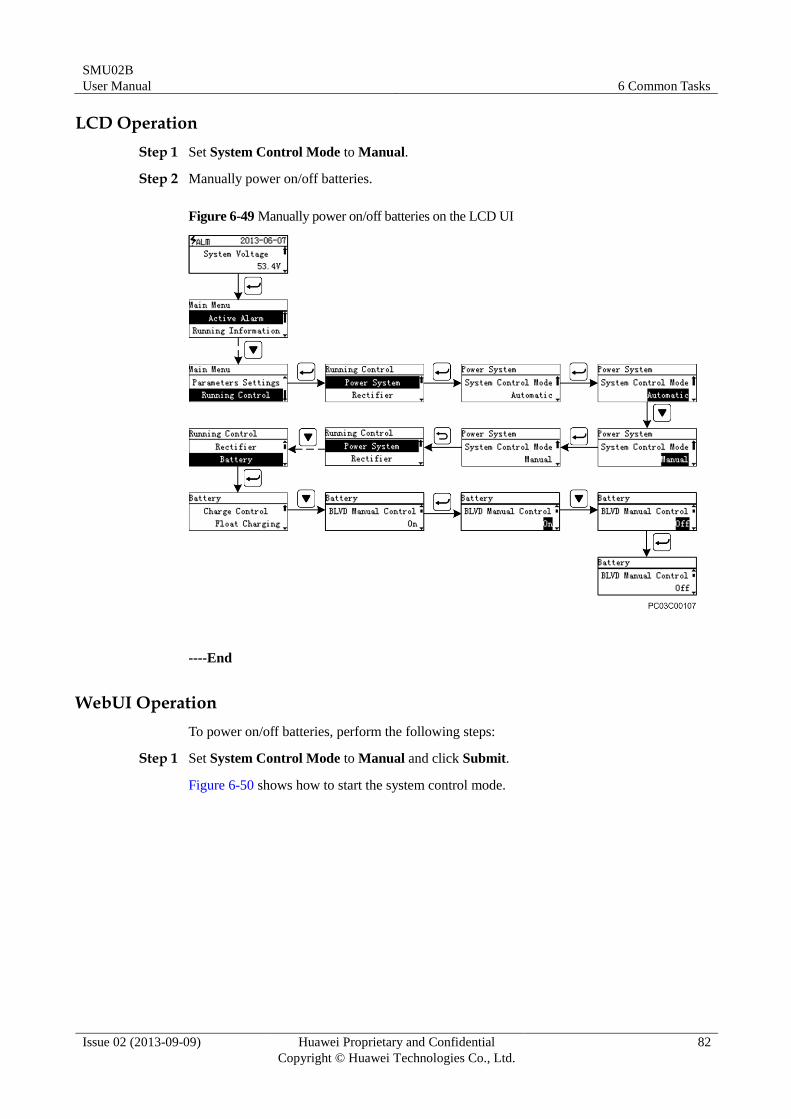
Step 2 Switch between equalized charging and float charging.
SMU02B
User Manual 6 Common Tasks
Issue 02 (2013-09-09) Huawei Proprietary and Confidential
Copyright © Huawei Technologies Co., Ltd.
81
Set Charge Control to Equalized Charging and click Submit to charge batteries in
equalized mode.
After the system control mode is restored to the automatic mode, equalized charging
converts into float charging when the condition is met.
Set Charge Control to Float Charging and click Submit to charge batteries in float
mode.
Figure 6-48 shows how to set equalized charging or float charging for batteries.
Figure 6-48 Setting equalized charging or float charging for batteries on the WebUI
----End
Powering On/Off Batteries
Context
Exercise caution when powering off batteries, because such operation may cause all loads to
experience power failures.
You can manually power on/off batteries only in manual mode.
Parameters
Table 6-5 Battery power-on/off parameter description
Parameter Description Default Value Value Range
BLVD Manual
Control
Powers on/off batteries. On On
Off
SMU02B
User Manual 6 Common Tasks
Issue 02 (2013-09-09) Huawei Proprietary and Confidential
Copyright © Huawei Technologies Co., Ltd.
82
LCD Operation
Step 1 Set System Control Mode to Manual.
Step 2 Manually power on/off batteries.
Figure 6-49 Manually power on/off batteries on the LCD UI
----End
WebUI Operation
To power on/off batteries, perform the following steps:
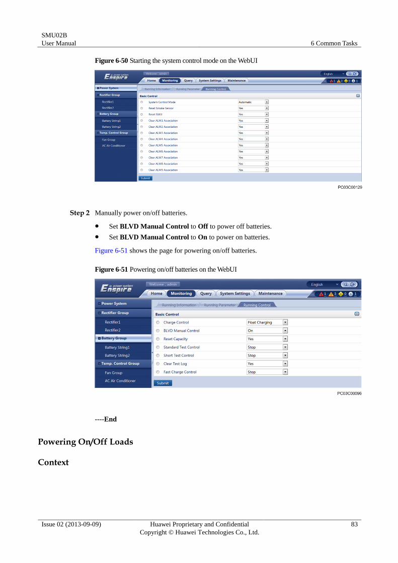
Step 1 Set System Control Mode to Manual and click Submit.
Figure 6-50 shows how to start the system control mode.
SMU02B
User Manual 6 Common Tasks
Issue 02 (2013-09-09) Huawei Proprietary and Confidential
Copyright © Huawei Technologies Co., Ltd.
83
Figure 6-50 Starting the system control mode on the WebUI
Step 2 Manually power on/off batteries.
Set BLVD Manual Control to Off to power off batteries.
Set BLVD Manual Control to On to power on batteries.
Figure 6-51 shows the page for powering on/off batteries.
Figure 6-51 Powering on/off batteries on the WebUI
----End
Powering On/Off Loads
Context
SMU02B
User Manual 6 Common Tasks
Issue 02 (2013-09-09) Huawei Proprietary and Confidential
Copyright © Huawei Technologies Co., Ltd.
84
Exercise caution when powering on/off loads, because such operation will cause loads to
experience power failures.
You can manually power on/off loads only in manual mode.
Parameters
Table 6-6 Load power-on/off parameter description
Parameter Description Default Value Value Range
LLVD1 Manual
Control
Powers on/off LLVD1. On On
Off
LCD Operation
Step 1 Set System Control Mode to Manual.
Step 2 Manually power on/off LLVD1.
Figure 6-52 Manually power on/off LLVD1 on the LCD UI
----End
WebUI Operation
To power on/off LLVD1, perform the following steps:
SMU02B
User Manual 6 Common Tasks
Issue 02 (2013-09-09) Huawei Proprietary and Confidential
Copyright © Huawei Technologies Co., Ltd.
85
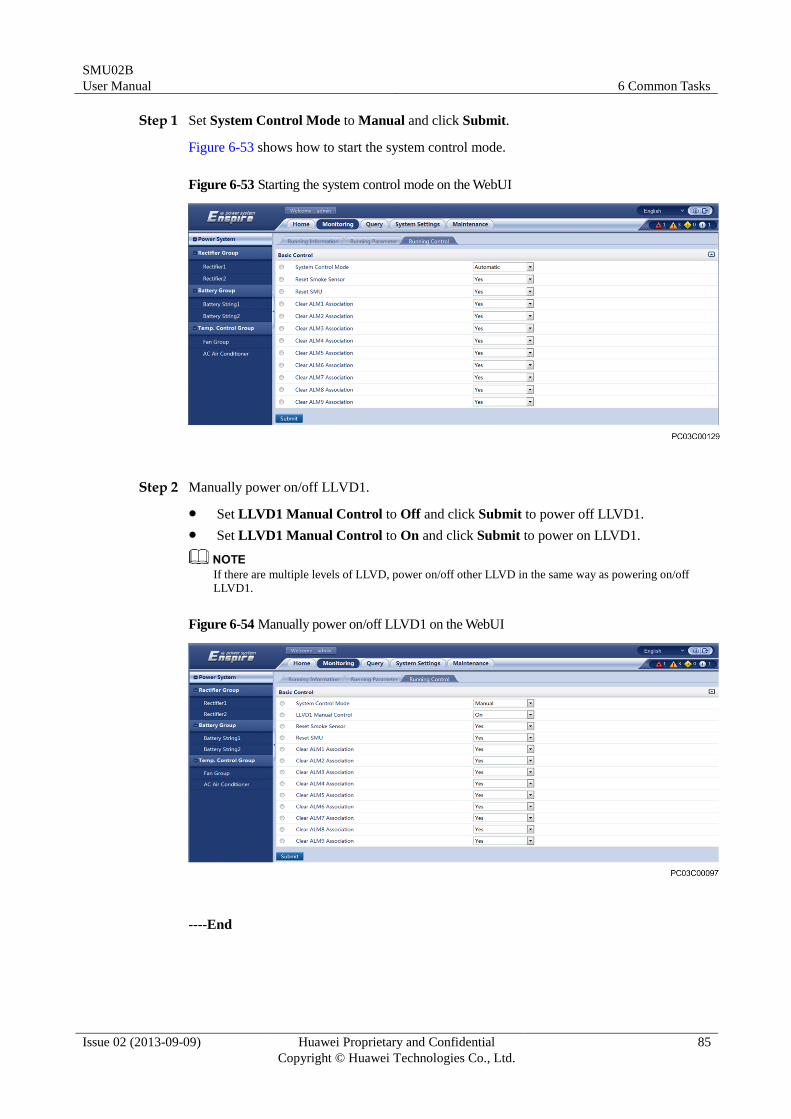
Step 1 Set System Control Mode to Manual and click Submit.
Figure 6-53 shows how to start the system control mode.
Figure 6-53 Starting the system control mode on the WebUI
Step 2 Manually power on/off LLVD1.
Set LLVD1 Manual Control to Off and click Submit to power off LLVD1.
Set LLVD1 Manual Control to On and click Submit to power on LLVD1.
If there are multiple levels of LLVD, power on/off other LLVD in the same way as powering on/off
LLVD1.
Figure 6-54 Manually power on/off LLVD1 on the WebUI
----End
SMU02B
User Manual 6 Common Tasks
Issue 02 (2013-09-09) Huawei Proprietary and Confidential
Copyright © Huawei Technologies Co., Ltd.
86
Starting and Shutting Down Rectifiers
Context
Exercise caution when shutting down rectifiers, because such operation will decrease the
maximum output power and may disconnect the power supply to loads.
You can manually start or shut down rectifiers only in manual mode.
Parameters
Table 6-7 Rectifier startup/shutdown parameter description
Parameter Description Default Value Value Range
Turn on All
Rectifiers
Starts all rectifiers. Yes Yes
Turn on/off
Rectifier
Controls the startup and
shutdown for a single
rectifier.
On On
Off
LCD Operation
Step 1 Set System Control Mode to Manual.
Step 2 Set Turn on All Rects. to Yes or set Turn on/off to Off.
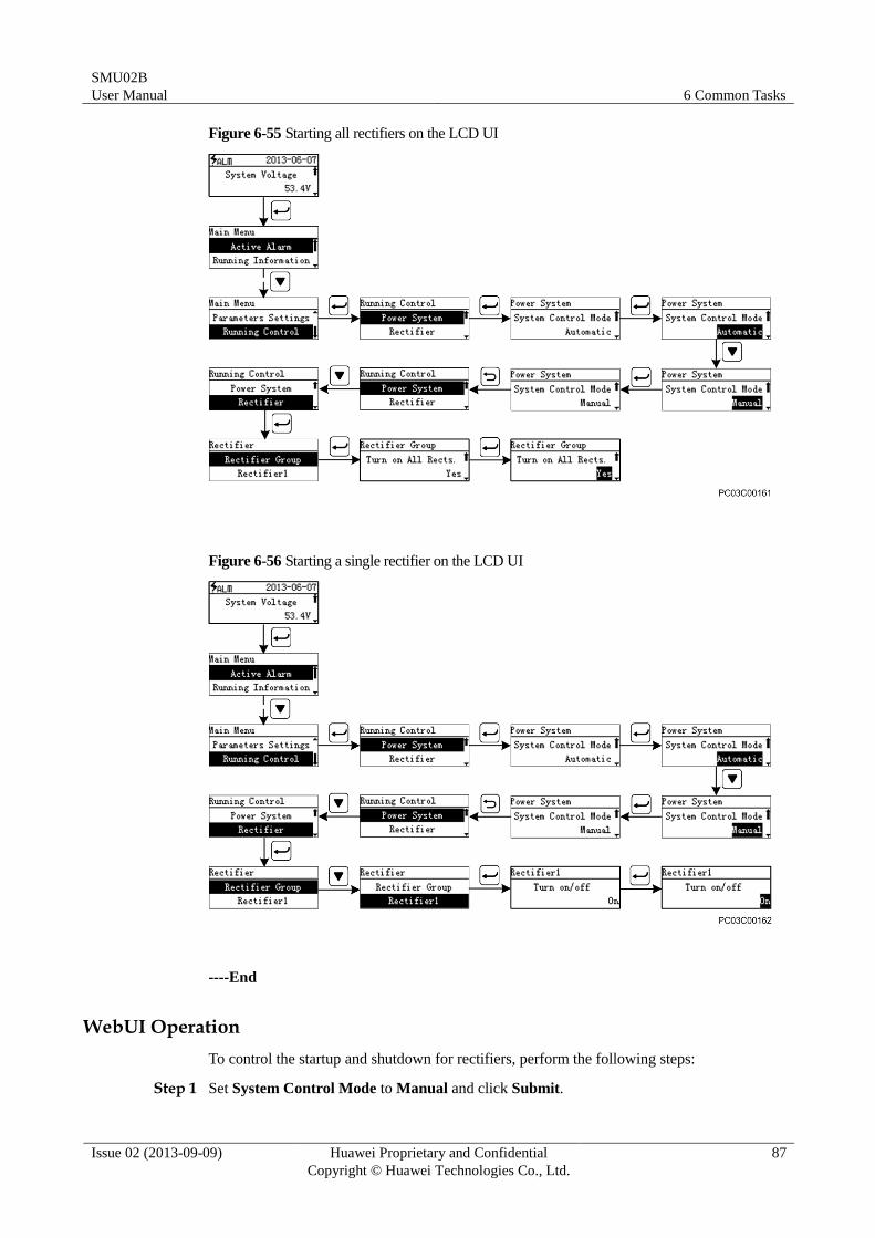
SMU02B
User Manual 6 Common Tasks
Issue 02 (2013-09-09) Huawei Proprietary and Confidential
Copyright © Huawei Technologies Co., Ltd.
87
Figure 6-55 Starting all rectifiers on the LCD UI
Figure 6-56 Starting a single rectifier on the LCD UI
----End
WebUI Operation
To control the startup and shutdown for rectifiers, perform the following steps:
Step 1 Set System Control Mode to Manual and click Submit.
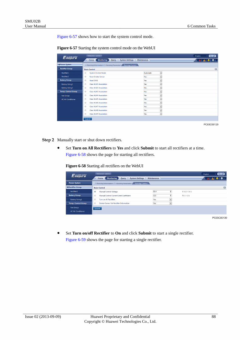
SMU02B
User Manual 6 Common Tasks
Issue 02 (2013-09-09) Huawei Proprietary and Confidential
Copyright © Huawei Technologies Co., Ltd.
88
Figure 6-57 shows how to start the system control mode.
Figure 6-57 Starting the system control mode on the WebUI
Step 2 Manually start or shut down rectifiers.
Set Turn on All Rectifiers to Yes and click Submit to start all rectifiers at a time.
Figure 6-58 shows the page for starting all rectifiers.
Figure 6-58 Starting all rectifiers on the WebUI
Set Turn on/off Rectifier to On and click Submit to start a single rectifier.
Figure 6-59 shows the page for starting a single rectifier.
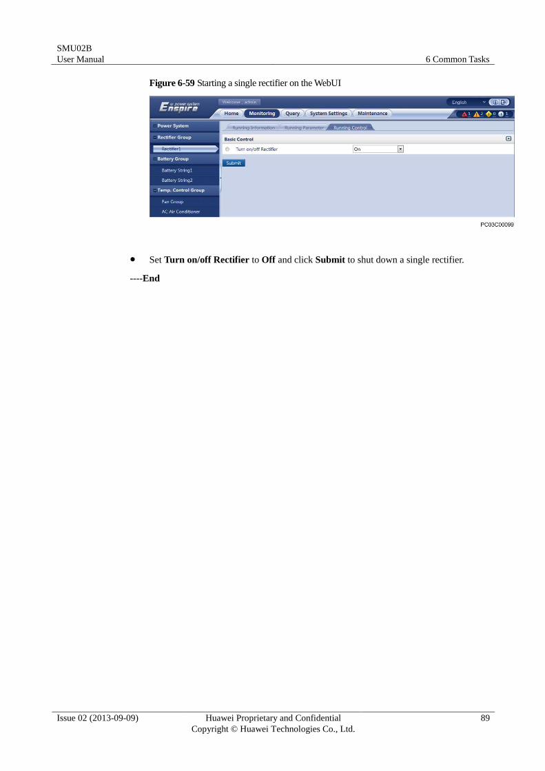
SMU02B
User Manual 6 Common Tasks
Issue 02 (2013-09-09) Huawei Proprietary and Confidential
Copyright © Huawei Technologies Co., Ltd.
89
Figure 6-59 Starting a single rectifier on the WebUI
Set Turn on/off Rectifier to Off and click Submit to shut down a single rectifier.
----End
SMU02B
User Manual 7 Remote Management
Issue 02 (2013-09-09) Huawei Proprietary and Confidential
Copyright © Huawei Technologies Co., Ltd.
90
7 Remote Management
7.1 NetEco Management
7.1.1 Networking Mode 1: over FE
Connecting a Communications Cable
Procedure
Step 1 Connect the FE port on the SMU by using a network cable, as shown in Figure 7-1.
Figure 7-1 Connecting a communications cable
(1) FE port
----End
Setting Parameters
Procedure
Step 1 Apply to the site or equipment room network administrator for a fixed IP address.
Step 2 Set the IP address, subnet mask, and gateway on the LCD, as shown in Table 7-1.
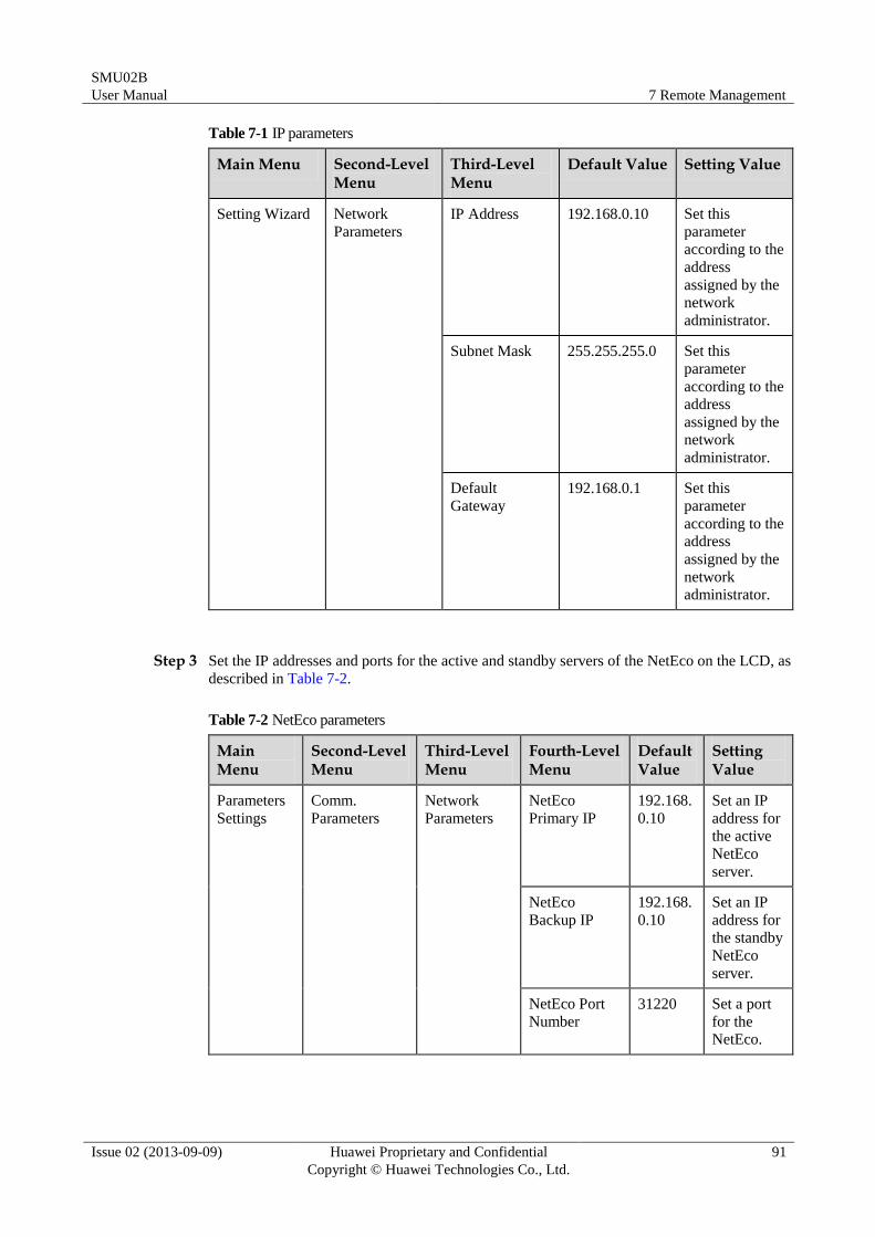
SMU02B
User Manual 7 Remote Management
Issue 02 (2013-09-09) Huawei Proprietary and Confidential
Copyright © Huawei Technologies Co., Ltd.
91
Table 7-1 IP parameters
Main Menu Second-Level Menu
Third-Level Menu
Default Value Setting Value
Setting Wizard Network
Parameters
IP Address 192.168.0.10 Set this
parameter
according to the
address
assigned by the
network
administrator.
Subnet Mask 255.255.255.0 Set this
parameter
according to the
address
assigned by the
network
administrator.
Default
Gateway
192.168.0.1 Set this
parameter
according to the
address
assigned by the
network
administrator.
Step 3 Set the IP addresses and ports for the active and standby servers of the NetEco on the LCD, as
described in Table 7-2.
Table 7-2 NetEco parameters
Main Menu
Second-Level Menu
Third-Level Menu
Fourth-Level Menu
Default Value
Setting Value
Parameters
Settings
Comm.
Parameters
Network
Parameters
NetEco
Primary IP
192.168.
0.10
Set an IP
address for
the active
NetEco
server.
NetEco
Backup IP
192.168.
0.10
Set an IP
address for
the standby
NetEco
server.
NetEco Port
Number
31220 Set a port
for the
NetEco.
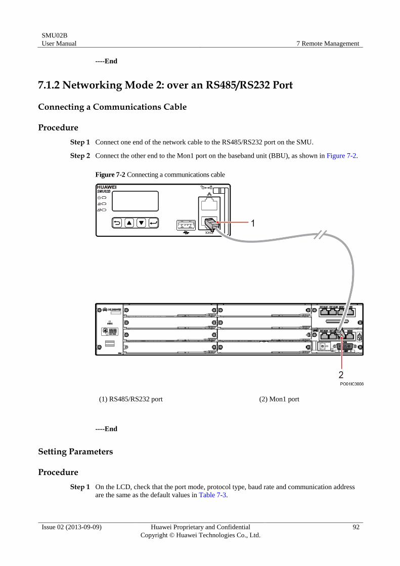
SMU02B
User Manual 7 Remote Management
Issue 02 (2013-09-09) Huawei Proprietary and Confidential
Copyright © Huawei Technologies Co., Ltd.
92
----End
7.1.2 Networking Mode 2: over an RS485/RS232 Port
Connecting a Communications Cable
Procedure
Step 1 Connect one end of the network cable to the RS485/RS232 port on the SMU.
Step 2 Connect the other end to the Mon1 port on the baseband unit (BBU), as shown in Figure 7-2.
Figure 7-2 Connecting a communications cable
(1) RS485/RS232 port (2) Mon1 port
----End
Setting Parameters
Procedure
Step 1 On the LCD, check that the port mode, protocol type, baud rate and communication address
are the same as the default values in Table 7-3.
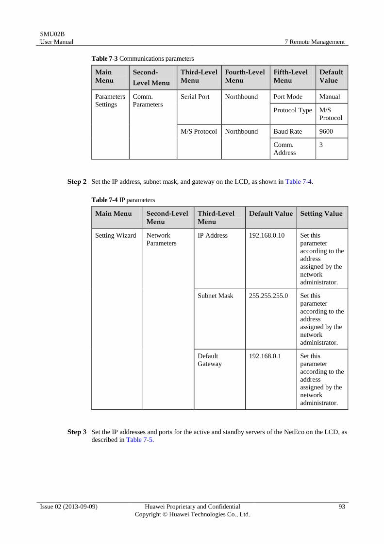
SMU02B
User Manual 7 Remote Management
Issue 02 (2013-09-09) Huawei Proprietary and Confidential
Copyright © Huawei Technologies Co., Ltd.
93
Table 7-3 Communications parameters
Main Menu
Second-
Level Menu
Third-Level Menu
Fourth-Level Menu
Fifth-Level Menu
Default Value
Parameters
Settings
Comm.
Parameters
Serial Port Northbound Port Mode Manual
Protocol Type M/S
Protocol
M/S Protocol Northbound Baud Rate 9600
Comm.
Address
3
Step 2 Set the IP address, subnet mask, and gateway on the LCD, as shown in Table 7-4.
Table 7-4 IP parameters
Main Menu Second-Level Menu
Third-Level Menu
Default Value Setting Value
Setting Wizard Network
Parameters
IP Address 192.168.0.10 Set this
parameter
according to the
address
assigned by the
network
administrator.
Subnet Mask 255.255.255.0 Set this
parameter
according to the
address
assigned by the
network
administrator.
Default
Gateway
192.168.0.1 Set this
parameter
according to the
address
assigned by the
network
administrator.
Step 3 Set the IP addresses and ports for the active and standby servers of the NetEco on the LCD, as
described in Table 7-5.
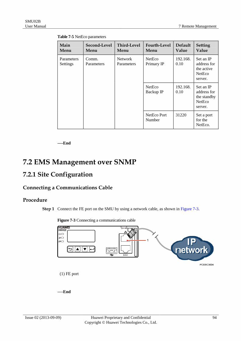
SMU02B
User Manual 7 Remote Management
Issue 02 (2013-09-09) Huawei Proprietary and Confidential
Copyright © Huawei Technologies Co., Ltd.
94
Table 7-5 NetEco parameters
Main Menu
Second-Level Menu
Third-Level Menu
Fourth-Level Menu
Default Value
Setting Value
Parameters
Settings
Comm.
Parameters
Network
Parameters
NetEco
Primary IP
192.168.
0.10
Set an IP
address for
the active
NetEco
server.
NetEco
Backup IP
192.168.
0.10
Set an IP
address for
the standby
NetEco
server.
NetEco Port
Number
31220 Set a port
for the
NetEco.
----End
7.2 EMS Management over SNMP
7.2.1 Site Configuration
Connecting a Communications Cable
Procedure
Step 1 Connect the FE port on the SMU by using a network cable, as shown in Figure 7-3.
Figure 7-3 Connecting a communications cable
(1) FE port
----End
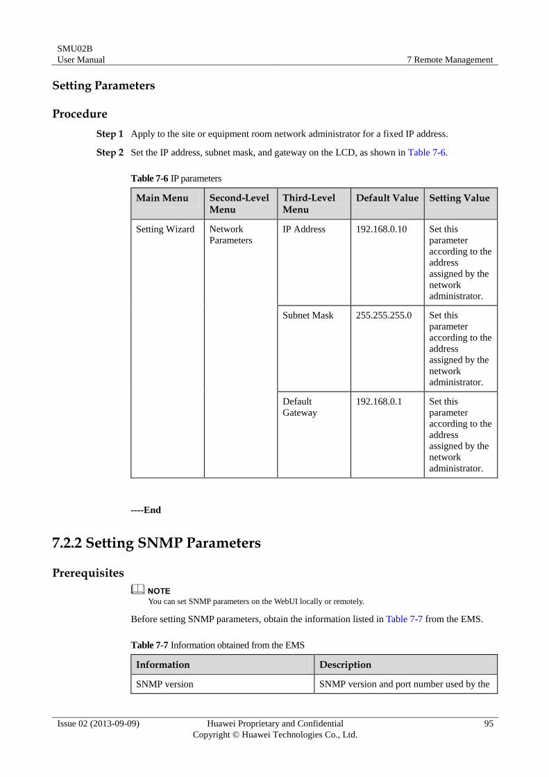
SMU02B
User Manual 7 Remote Management
Issue 02 (2013-09-09) Huawei Proprietary and Confidential
Copyright © Huawei Technologies Co., Ltd.
95
Setting Parameters
Procedure
Step 1 Apply to the site or equipment room network administrator for a fixed IP address.
Step 2 Set the IP address, subnet mask, and gateway on the LCD, as shown in Table 7-6.
Table 7-6 IP parameters
Main Menu Second-Level Menu
Third-Level Menu
Default Value Setting Value
Setting Wizard Network
Parameters
IP Address 192.168.0.10 Set this
parameter
according to the
address
assigned by the
network
administrator.
Subnet Mask 255.255.255.0 Set this
parameter
according to the
address
assigned by the
network
administrator.
Default
Gateway
192.168.0.1 Set this
parameter
according to the
address
assigned by the
network
administrator.
----End
7.2.2 Setting SNMP Parameters
Prerequisites
You can set SNMP parameters on the WebUI locally or remotely.
Before setting SNMP parameters, obtain the information listed in Table 7-7 from the EMS.
Table 7-7 Information obtained from the EMS
Information Description
SNMP version SNMP version and port number used by the
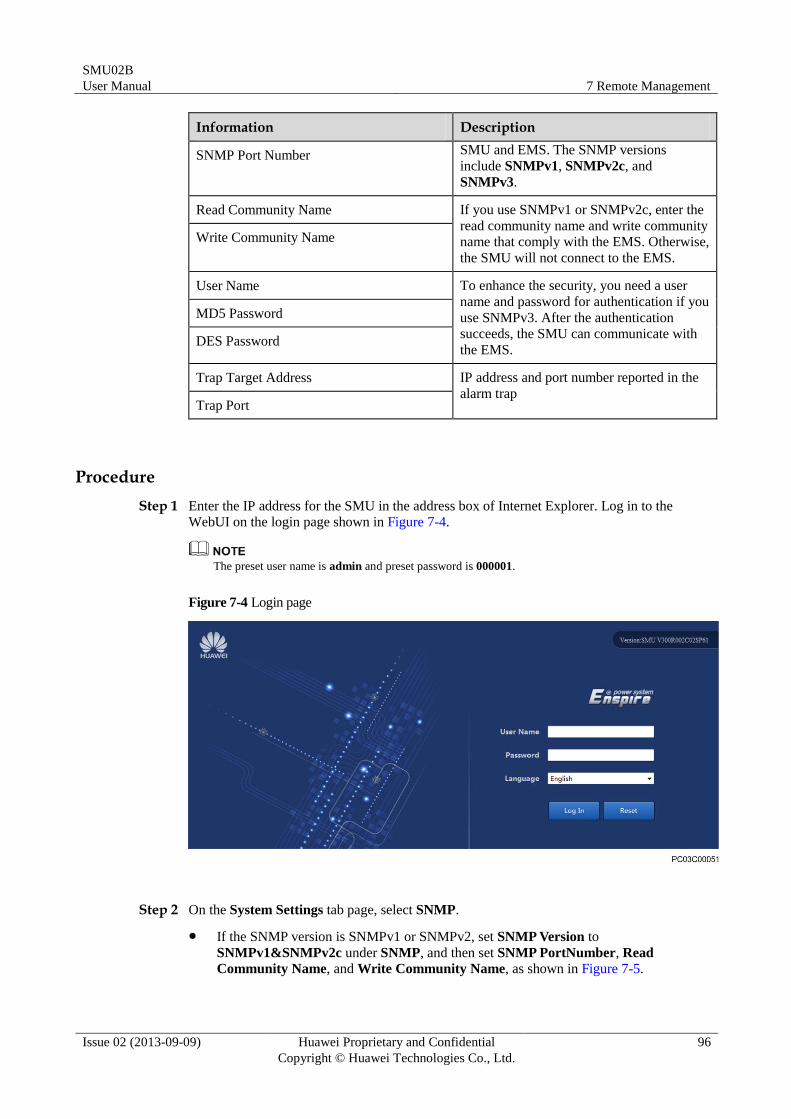
SMU02B
User Manual 7 Remote Management
Issue 02 (2013-09-09) Huawei Proprietary and Confidential
Copyright © Huawei Technologies Co., Ltd.
96
Information Description
SNMP Port Number SMU and EMS. The SNMP versions
include SNMPv1, SNMPv2c, and
SNMPv3.
Read Community Name If you use SNMPv1 or SNMPv2c, enter the
read community name and write community
name that comply with the EMS. Otherwise,
the SMU will not connect to the EMS.
Write Community Name
User Name To enhance the security, you need a user
name and password for authentication if you
use SNMPv3. After the authentication
succeeds, the SMU can communicate with
the EMS.
MD5 Password
DES Password
Trap Target Address IP address and port number reported in the
alarm trap Trap Port
Procedure
Step 1 Enter the IP address for the SMU in the address box of Internet Explorer. Log in to the
WebUI on the login page shown in Figure 7-4.
The preset user name is admin and preset password is 000001.
Figure 7-4 Login page
Step 2 On the System Settings tab page, select SNMP.
If the SNMP version is SNMPv1 or SNMPv2, set SNMP Version to
SNMPv1&SNMPv2c under SNMP, and then set SNMP PortNumber, Read
Community Name, and Write Community Name, as shown in Figure 7-5.
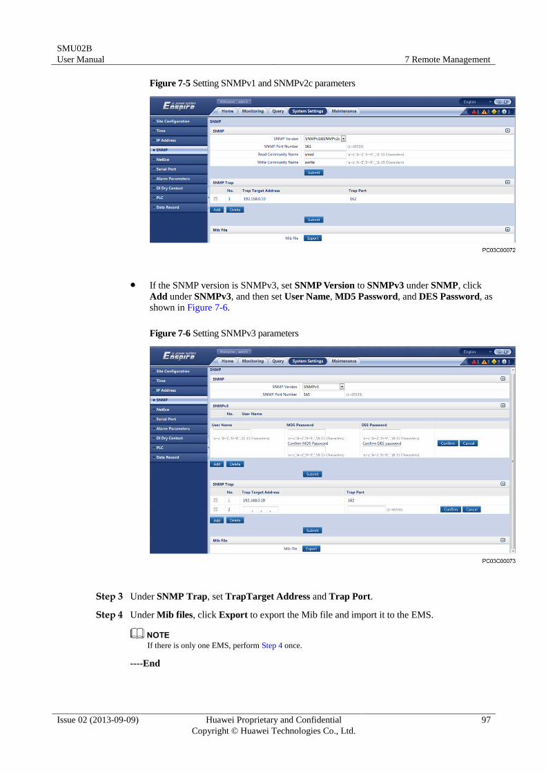
SMU02B
User Manual 7 Remote Management
Issue 02 (2013-09-09) Huawei Proprietary and Confidential
Copyright © Huawei Technologies Co., Ltd.
97
Figure 7-5 Setting SNMPv1 and SNMPv2c parameters
If the SNMP version is SNMPv3, set SNMP Version to SNMPv3 under SNMP, click
Add under SNMPv3, and then set User Name, MD5 Password, and DES Password, as
shown in Figure 7-6.
Figure 7-6 Setting SNMPv3 parameters
Step 3 Under SNMP Trap, set TrapTarget Address and Trap Port.
Step 4 Under Mib files, click Export to export the Mib file and import it to the EMS.
If there is only one EMS, perform Step 4 once.
----End
SMU02B
User Manual 7 Remote Management
Issue 02 (2013-09-09) Huawei Proprietary and Confidential
Copyright © Huawei Technologies Co., Ltd.
98
7.2.3 EMS Commissioning
You can query the power system operating status, active alarms, and the names of
user-defined dry contact inputs, and configure dry contact outputs on the element
management system (EMS) that is connected over the Simple Network Management Protocol
(SNMP).
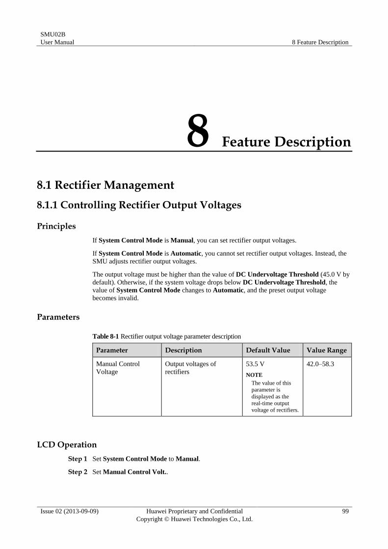
SMU02B
User Manual 8 Feature Description
Issue 02 (2013-09-09) Huawei Proprietary and Confidential
Copyright © Huawei Technologies Co., Ltd.
99
8 Feature Description
8.1 Rectifier Management
8.1.1 Controlling Rectifier Output Voltages
Principles
If System Control Mode is Manual, you can set rectifier output voltages.
If System Control Mode is Automatic, you cannot set rectifier output voltages. Instead, the
SMU adjusts rectifier output voltages.
The output voltage must be higher than the value of DC Undervoltage Threshold (45.0 V by
default). Otherwise, if the system voltage drops below DC Undervoltage Threshold, the
value of System Control Mode changes to Automatic, and the preset output voltage
becomes invalid.
Parameters
Table 8-1 Rectifier output voltage parameter description
Parameter Description Default Value Value Range
Manual Control
Voltage
Output voltages of
rectifiers
53.5 V
NOTE
The value of this
parameter is
displayed as the
real-time output
voltage of rectifiers.
42.0–58.3
LCD Operation
Step 1 Set System Control Mode to Manual.
Step 2 Set Manual Control Volt..
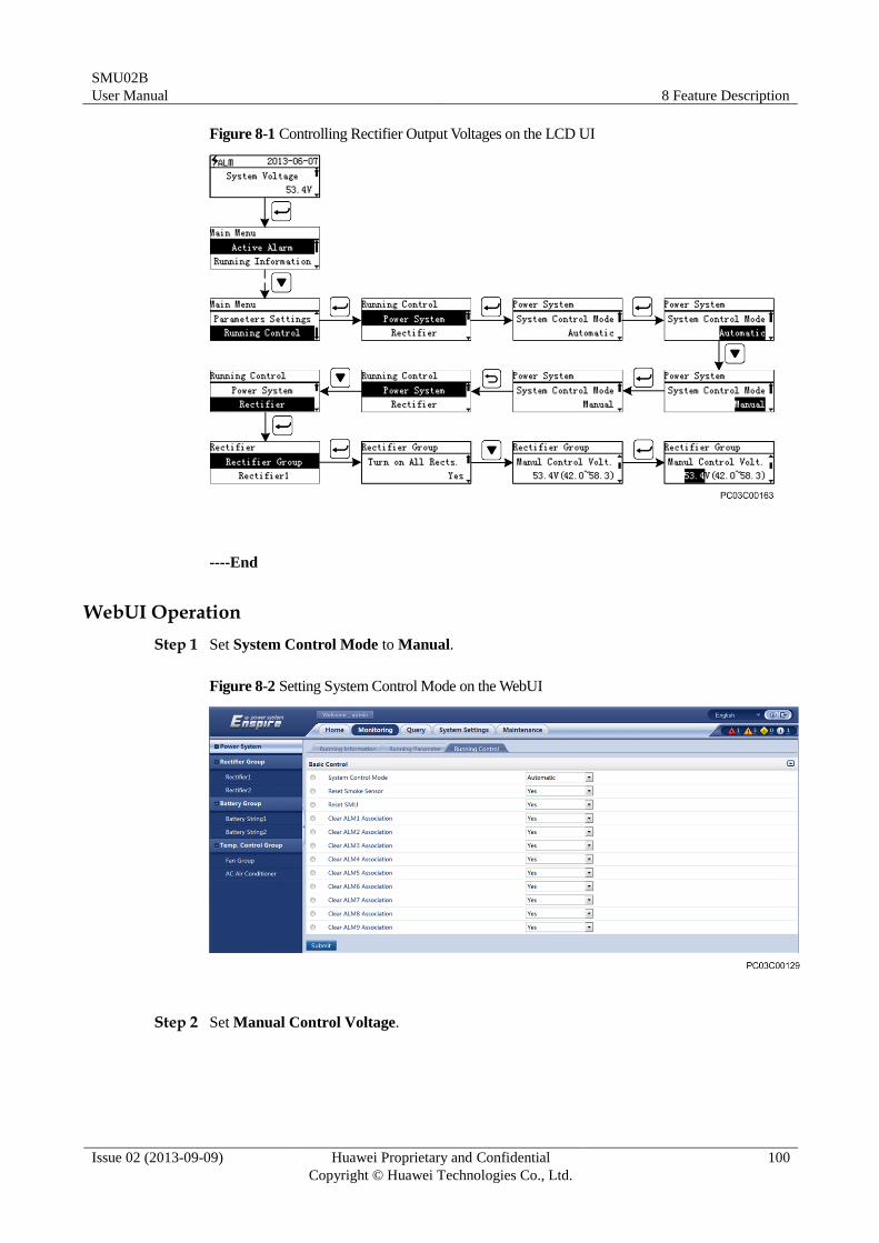
SMU02B
User Manual 8 Feature Description
Issue 02 (2013-09-09) Huawei Proprietary and Confidential
Copyright © Huawei Technologies Co., Ltd.
100
Figure 8-1 Controlling Rectifier Output Voltages on the LCD UI
----End
WebUI Operation
Step 1 Set System Control Mode to Manual.
Figure 8-2 Setting System Control Mode on the WebUI
Step 2 Set Manual Control Voltage.
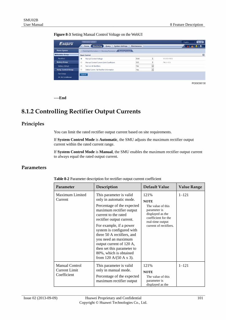
SMU02B
User Manual 8 Feature Description
Issue 02 (2013-09-09) Huawei Proprietary and Confidential
Copyright © Huawei Technologies Co., Ltd.
101
Figure 8-3 Setting Manual Control Voltage on the WebUI
----End
8.1.2 Controlling Rectifier Output Currents
Principles
You can limit the rated rectifier output current based on site requirements.
If System Control Mode is Automatic, the SMU adjusts the maximum rectifier output
current within the rated current range.
If System Control Mode is Manual, the SMU enables the maximum rectifier output current
to always equal the rated output current.
Parameters
Table 8-2 Parameter description for rectifier output current coefficient
Parameter Description Default Value Value Range
Maximum Limited
Current
This parameter is valid
only in automatic mode.
Percentage of the expected
maximum rectifier output
current to the rated
rectifier output current.
For example, if a power
system is configured with
three 50 A rectifiers, and
you need an maximum
output current of 120 A,
then set this parameter to
80%, which is obtained
from 120 A/(50 A x 3).
121%
NOTE
The value of this
parameter is
displayed as the
coefficient for the
real-time output
current of rectifiers.
1–121
Manual Control
Current Limit
Coefficient
This parameter is valid
only in manual mode.
Percentage of the expected
maximum rectifier output
121%
NOTE
The value of this
parameter is
displayed as the
1–121
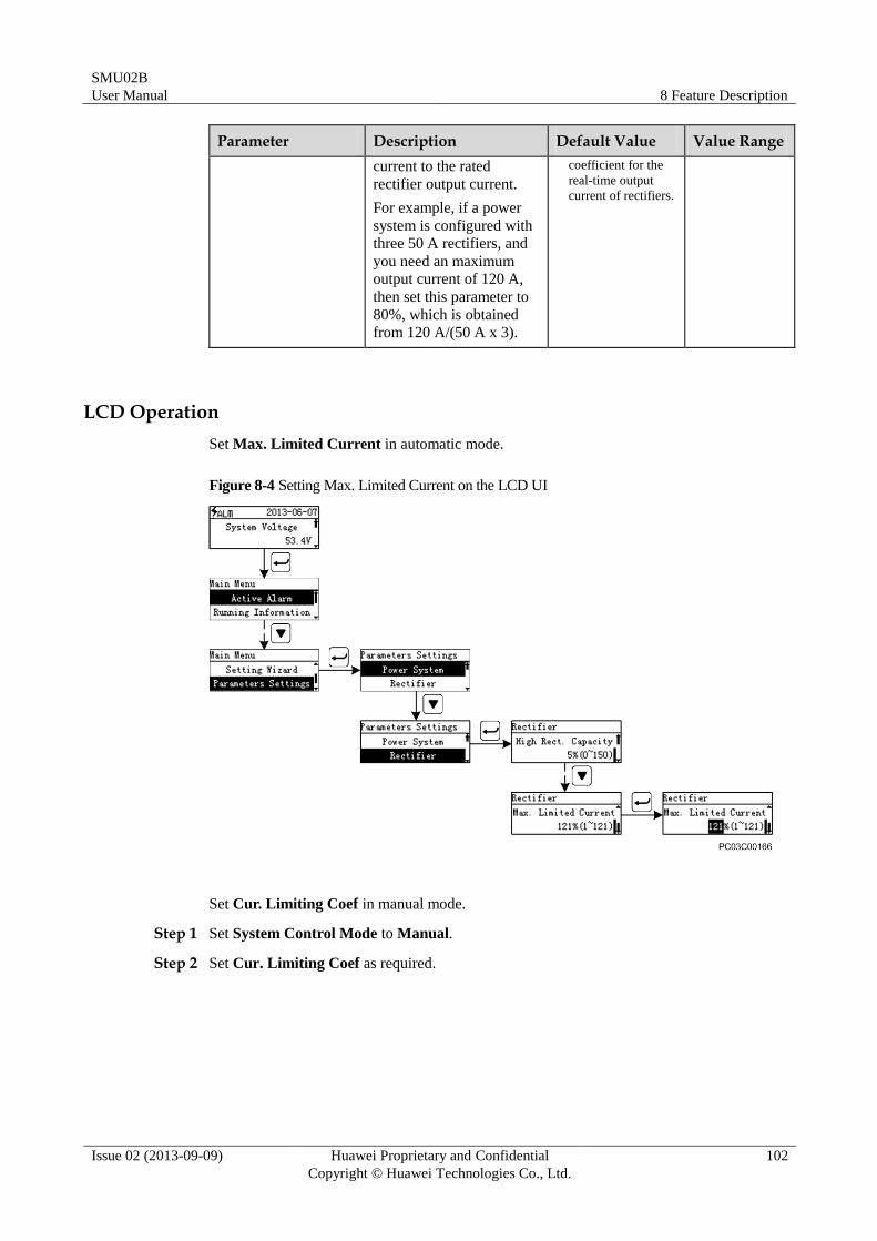
SMU02B
User Manual 8 Feature Description
Issue 02 (2013-09-09) Huawei Proprietary and Confidential
Copyright © Huawei Technologies Co., Ltd.
102
Parameter Description Default Value Value Range
current to the rated
rectifier output current.
For example, if a power
system is configured with
three 50 A rectifiers, and
you need an maximum
output current of 120 A,
then set this parameter to
80%, which is obtained
from 120 A/(50 A x 3).
coefficient for the
real-time output
current of rectifiers.
LCD Operation
Set Max. Limited Current in automatic mode.
Figure 8-4 Setting Max. Limited Current on the LCD UI
Set Cur. Limiting Coef in manual mode.
Step 1 Set System Control Mode to Manual.
Step 2 Set Cur. Limiting Coef as required.
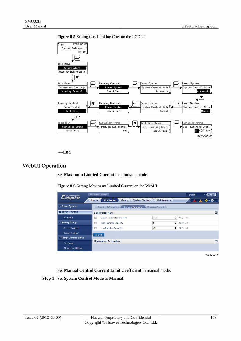
SMU02B
User Manual 8 Feature Description
Issue 02 (2013-09-09) Huawei Proprietary and Confidential
Copyright © Huawei Technologies Co., Ltd.
103
Figure 8-5 Setting Cur. Limiting Coef on the LCD UI
----End
WebUI Operation
Set Maximum Limited Current in automatic mode.
Figure 8-6 Setting Maximum Limited Current on the WebUI
Set Manual Control Current Limit Coefficient in manual mode.
Step 1 Set System Control Mode to Manual.
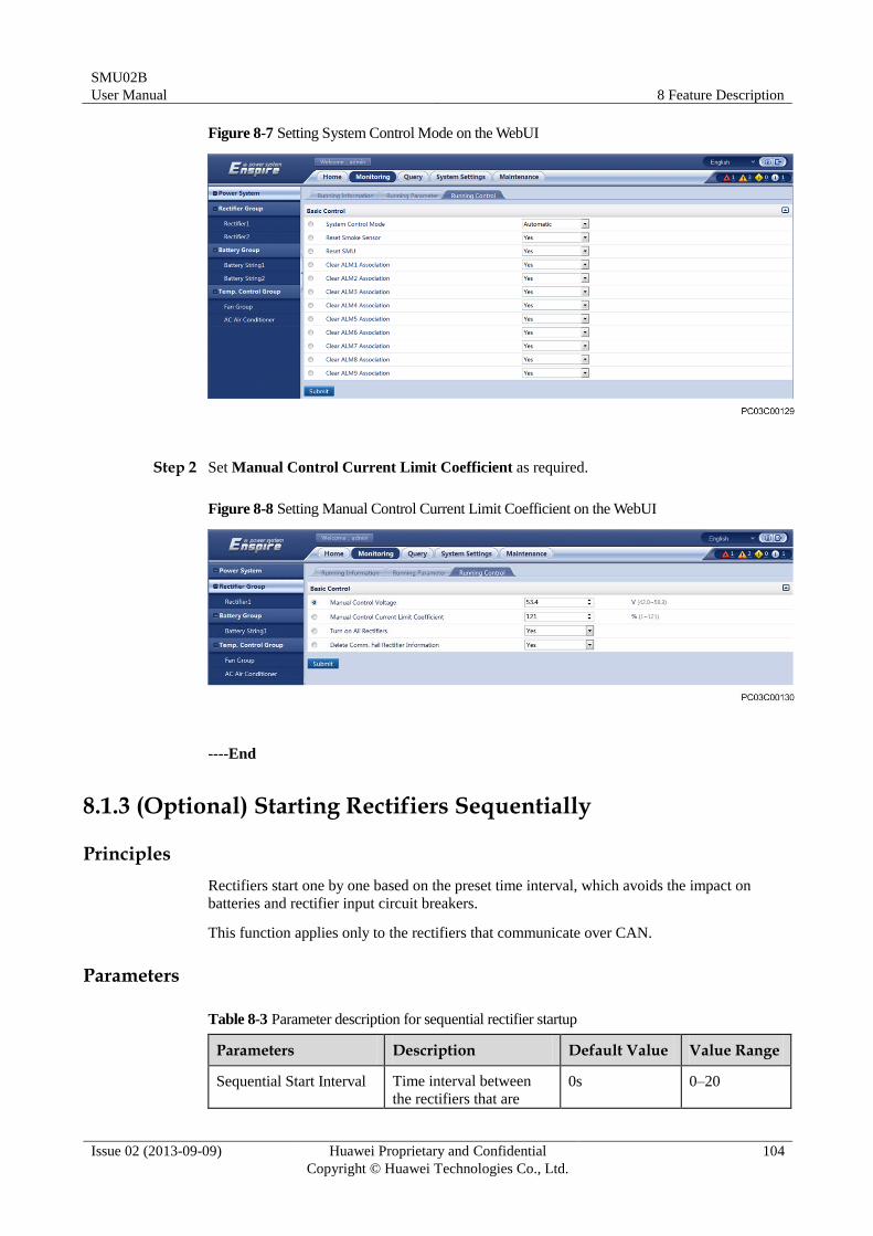
SMU02B
User Manual 8 Feature Description
Issue 02 (2013-09-09) Huawei Proprietary and Confidential
Copyright © Huawei Technologies Co., Ltd.
104
Figure 8-7 Setting System Control Mode on the WebUI
Step 2 Set Manual Control Current Limit Coefficient as required.
Figure 8-8 Setting Manual Control Current Limit Coefficient on the WebUI
----End
8.1.3 (Optional) Starting Rectifiers Sequentially
Principles
Rectifiers start one by one based on the preset time interval, which avoids the impact on
batteries and rectifier input circuit breakers.
This function applies only to the rectifiers that communicate over CAN.
Parameters
Table 8-3 Parameter description for sequential rectifier startup
Parameters Description Default Value Value Range
Sequential Start Interval Time interval between
the rectifiers that are 0s 0–20
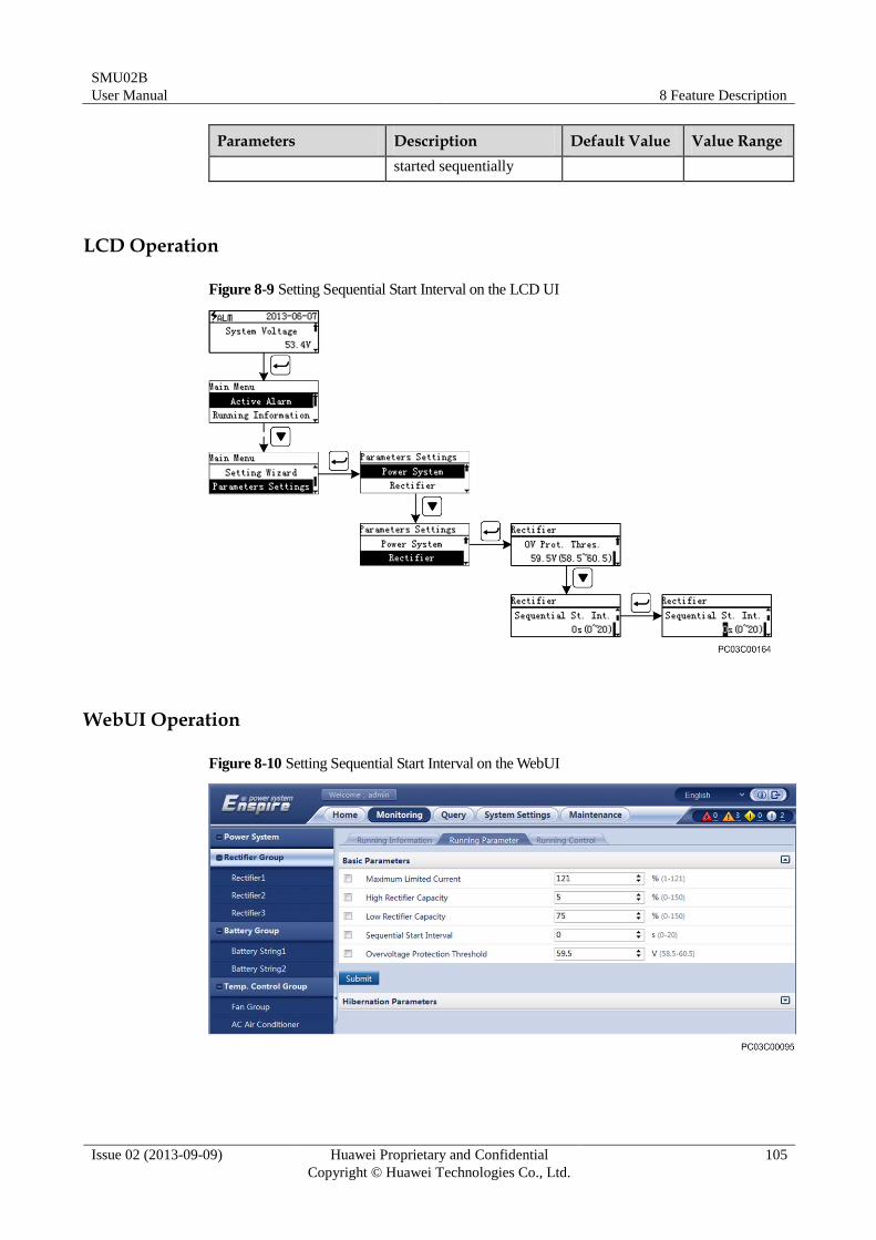
SMU02B
User Manual 8 Feature Description
Issue 02 (2013-09-09) Huawei Proprietary and Confidential
Copyright © Huawei Technologies Co., Ltd.
105
Parameters Description Default Value Value Range
started sequentially
LCD Operation
Figure 8-9 Setting Sequential Start Interval on the LCD UI
WebUI Operation
Figure 8-10 Setting Sequential Start Interval on the WebUI
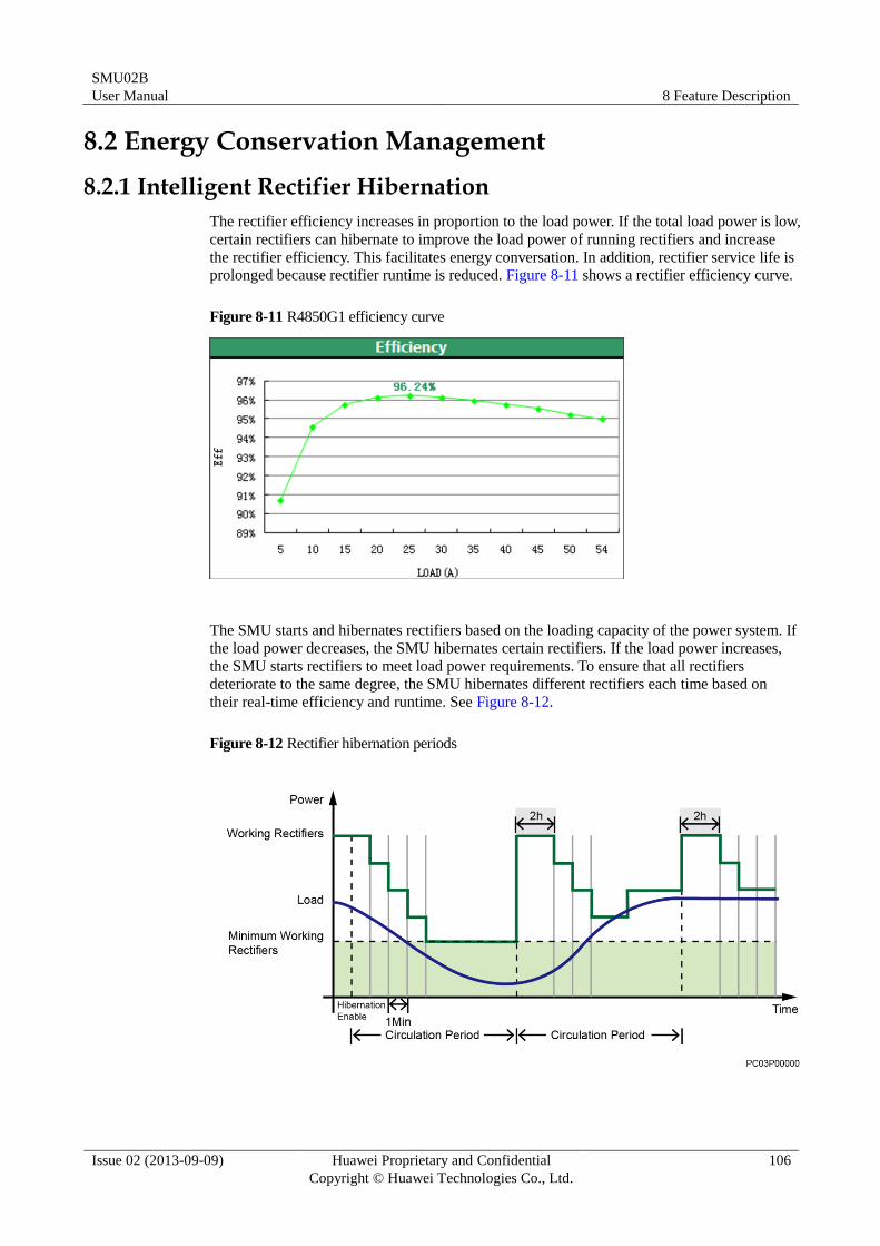
SMU02B
User Manual 8 Feature Description
Issue 02 (2013-09-09) Huawei Proprietary and Confidential
Copyright © Huawei Technologies Co., Ltd.
106
8.2 Energy Conservation Management
8.2.1 Intelligent Rectifier Hibernation
The rectifier efficiency increases in proportion to the load power. If the total load power is low,
certain rectifiers can hibernate to improve the load power of running rectifiers and increase
the rectifier efficiency. This facilitates energy conversation. In addition, rectifier service life is
prolonged because rectifier runtime is reduced. Figure 8-11 shows a rectifier efficiency curve.
Figure 8-11 R4850G1 efficiency curve
The SMU starts and hibernates rectifiers based on the loading capacity of the power system. If
the load power decreases, the SMU hibernates certain rectifiers. If the load power increases,
the SMU starts rectifiers to meet load power requirements. To ensure that all rectifiers
deteriorate to the same degree, the SMU hibernates different rectifiers each time based on
their real-time efficiency and runtime. See Figure 8-12.
Figure 8-12 Rectifier hibernation periods
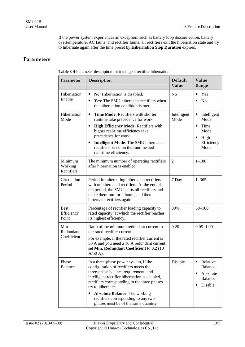
SMU02B
User Manual 8 Feature Description
Issue 02 (2013-09-09) Huawei Proprietary and Confidential
Copyright © Huawei Technologies Co., Ltd.
107
If the power system experiences an exception, such as battery loop disconnection, battery
overtemperature, AC faults, and rectifier faults, all rectifiers exit the hibernation state and try
to hibernate again after the time preset by Hibernation Stop Duration expires.
Parameters
Table 8-4 Parameter description for intelligent rectifier hibernation
Parameter Description Default Value
Value Range
Hibernation
Enable
No: Hibernation is disabled.
Yes: The SMU hibernates rectifiers when
the hibernation condition is met.
No Yes
No
Hibernation
Mode
Time Mode: Rectifiers with shorter
runtime take precedence for work.
High Efficiency Mode: Rectifiers with
higher real-time efficiency take
precedence for work.
Intelligent Mode: The SMU hibernates
rectifiers based on the runtime and
real-time efficiency.
Intelligent
Mode
Intelligent
Mode
Time
Mode
High
Efficiency
Mode
Minimum
Working
Rectifiers
The minimum number of operating rectifiers
after hibernation is enabled
2 1–100
Circulation
Period
Period for alternating hibernated rectifiers
with unhibernated rectifiers. At the end of
the period, the SMU starts all rectifiers and
make them run for 2 hours, and then
hibernate rectifiers again.
7 Day 1–365
Best
Efficiency
Point
Percentage of rectifier loading capacity to
rated capacity, at which the rectifier reaches
its highest efficiency.
80% 50–100
Min.
Redundant
Coefficient
Ratio of the minimum redundant current to
the rated rectifier current.
For example, if the rated rectifier current is
50 A and you need a 10 A redundant current,
set Min. Redundant Coefficient to 0.2 (10
A/50 A).
0.20 0.05–1.00
Phase
Balance
In a three-phase power system, if the
configuration of rectifiers meets the
three-phase balance requirement, and
intelligent rectifier hibernation is enabled,
rectifiers corresponding to the three phases
try to hibernate.
Absolute Balance: The working
rectifiers corresponding to any two
phases must be of the same quantity.
Disable Relative
Balance
Absolute
Balance
Disable
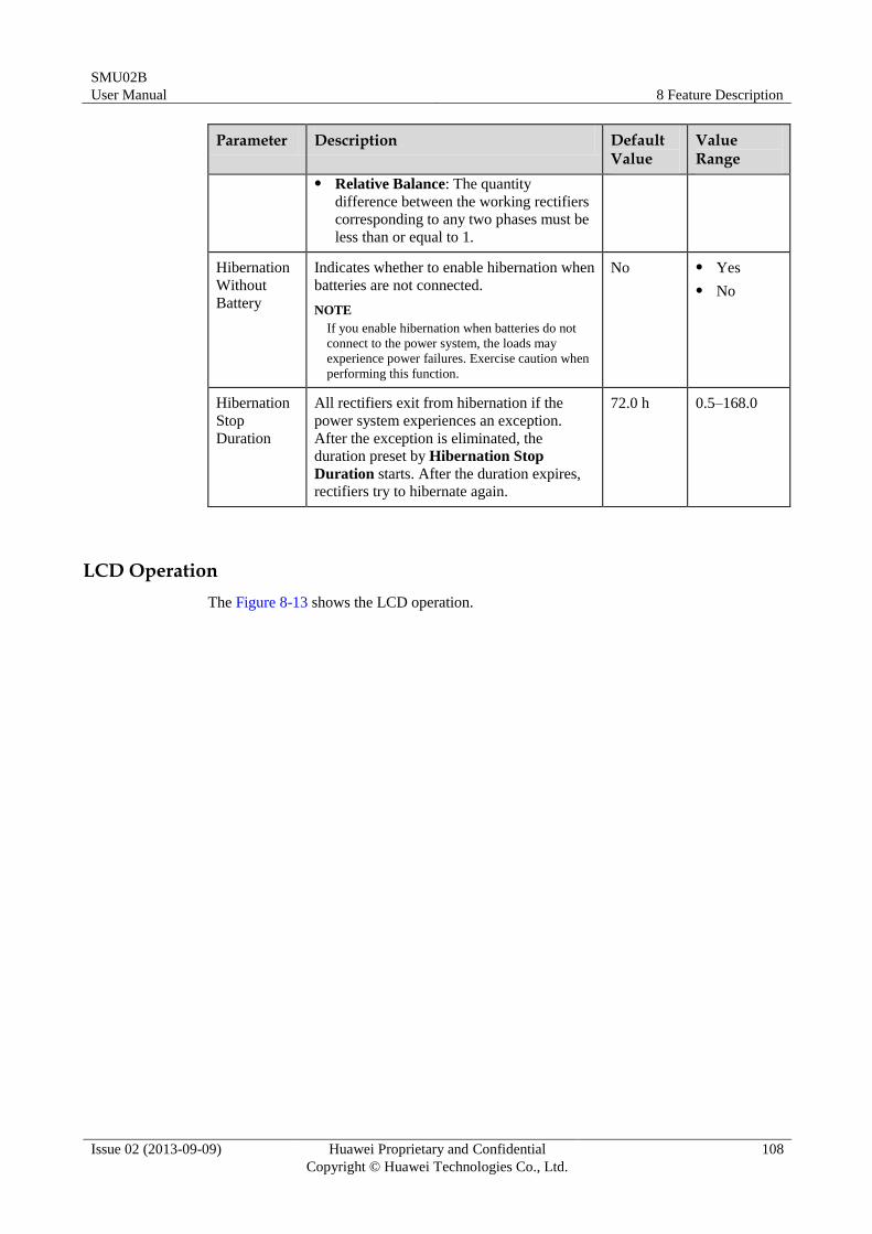
SMU02B
User Manual 8 Feature Description
Issue 02 (2013-09-09) Huawei Proprietary and Confidential
Copyright © Huawei Technologies Co., Ltd.
108
Parameter Description Default Value
Value Range
Relative Balance: The quantity
difference between the working rectifiers
corresponding to any two phases must be
less than or equal to 1.
Hibernation
Without
Battery
Indicates whether to enable hibernation when
batteries are not connected.
NOTE
If you enable hibernation when batteries do not
connect to the power system, the loads may
experience power failures. Exercise caution when
performing this function.
No Yes
No
Hibernation
Stop
Duration
All rectifiers exit from hibernation if the
power system experiences an exception.
After the exception is eliminated, the
duration preset by Hibernation Stop
Duration starts. After the duration expires,
rectifiers try to hibernate again.
72.0 h 0.5–168.0
LCD Operation
The Figure 8-13 shows the LCD operation.
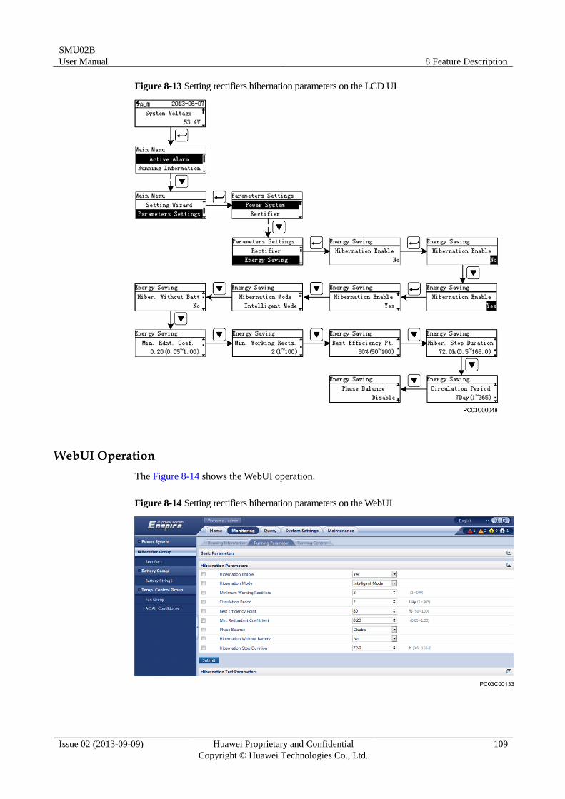
SMU02B
User Manual 8 Feature Description
Issue 02 (2013-09-09) Huawei Proprietary and Confidential
Copyright © Huawei Technologies Co., Ltd.
109
Figure 8-13 Setting rectifiers hibernation parameters on the LCD UI
WebUI Operation
The Figure 8-14 shows the WebUI operation.
Figure 8-14 Setting rectifiers hibernation parameters on the WebUI
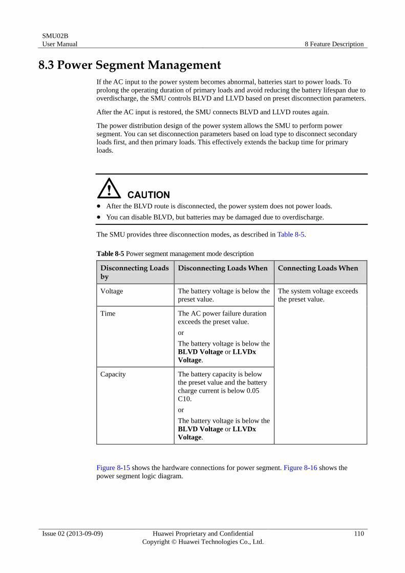
SMU02B
User Manual 8 Feature Description
Issue 02 (2013-09-09) Huawei Proprietary and Confidential
Copyright © Huawei Technologies Co., Ltd.
110
8.3 Power Segment Management
If the AC input to the power system becomes abnormal, batteries start to power loads. To
prolong the operating duration of primary loads and avoid reducing the battery lifespan due to
overdischarge, the SMU controls BLVD and LLVD based on preset disconnection parameters.
After the AC input is restored, the SMU connects BLVD and LLVD routes again.
The power distribution design of the power system allows the SMU to perform power
segment. You can set disconnection parameters based on load type to disconnect secondary
loads first, and then primary loads. This effectively extends the backup time for primary
loads.
After the BLVD route is disconnected, the power system does not power loads.
You can disable BLVD, but batteries may be damaged due to overdischarge.
The SMU provides three disconnection modes, as described in Table 8-5.
Table 8-5 Power segment management mode description
Disconnecting Loads by
Disconnecting Loads When Connecting Loads When
Voltage The battery voltage is below the
preset value.
The system voltage exceeds
the preset value.
Time The AC power failure duration
exceeds the preset value.
or
The battery voltage is below the
BLVD Voltage or LLVDx
Voltage.
Capacity The battery capacity is below
the preset value and the battery
charge current is below 0.05
C10.
or
The battery voltage is below the
BLVD Voltage or LLVDx
Voltage.
Figure 8-15 shows the hardware connections for power segment. Figure 8-16 shows the
power segment logic diagram.
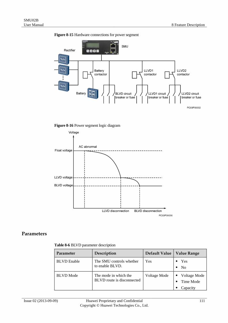
SMU02B
User Manual 8 Feature Description
Issue 02 (2013-09-09) Huawei Proprietary and Confidential
Copyright © Huawei Technologies Co., Ltd.
111
Figure 8-15 Hardware connections for power segment
Figure 8-16 Power segment logic diagram
Parameters
Table 8-6 BLVD parameter description
Parameter Description Default Value Value Range
BLVD Enable The SMU controls whether
to enable BLVD.
Yes Yes
No
BLVD Mode The mode in which the
BLVD route is disconnected
Voltage Mode Voltage Mode
Time Mode
Capacity
SMU02B
User Manual 8 Feature Description
Issue 02 (2013-09-09) Huawei Proprietary and Confidential
Copyright © Huawei Technologies Co., Ltd.
112
Parameter Description Default Value Value Range
Mode
BLVD Voltage If the battery voltage is
below the value of this
parameter, the BLVD route
is disconnected.
NOTE
The value of BLVD Voltage
must be lower than the value
of BLVD Connection Voltage.
43.2 V 35.0–56.0
BLVD Connection
Voltage
If the system voltage
exceeds the value of this
parameter, the BLVD route
is connected.
51.5 V 37.0–58.0
BLVD Time If the battery discharge
duration exceeds the value
of this parameter, the BLVD
route is disconnected.
This parameter is valid
when BLVD Mode is Time
Mode.
480 Min 5–1000
BLVD Capacity If the remaining battery
capacity is below the value
of this parameter and the
battery charge current is
below 0.05 C10, the BLVD
route is disconnected.
This parameter is valid
when BLVD Mode is
Capacity Mode.
5% 0–99
BLVD Delay Time After the BLVD Warning
alarm is generated, the
LLVD route is disconnected
after the BLVD Delay
Time.
60s 5-90
Table 8-7 LLVDx parameter description
Parameter Description Default Value Value Range
LLVDx Enable The SMU controls whether
to enable LLVD.
Yes Yes
No
LLVDx Mode The mode in which the
LLVD route is disconnected
Voltage Mode Voltage
Mode
Time Mode
Capacity
SMU02B
User Manual 8 Feature Description
Issue 02 (2013-09-09) Huawei Proprietary and Confidential
Copyright © Huawei Technologies Co., Ltd.
113
Parameter Description Default Value Value Range
Mode
LLVDx Voltage If the battery voltage is
below the value of this
parameter, the LLVD route
is disconnected.
44.0 V 35.0–56.0
LLVDx Connection
Voltage
If the system voltage
exceeds the value of this
parameter, the LLVD route
is connected.
51.5 V 37.0–58.0
LLVDx Time If the battery discharge
duration exceeds the value
of this parameter, the LLVD
route is disconnected.
This parameter is valid when
LLVDx Mode is Time
Mode.
360 Min 5–1000
LLVDx Capacity If the remaining battery
capacity is below the value
of this parameter and the
battery charge current is
below 0.05 C10, the LLVD
route is disconnected.
This parameter is valid when
LLVDx Mode is Capacity
Mode.
15% 0–99
LLVD Delay Time After the LLVDx Warning
alarm is generated, the
LLVD route is disconnected
after the LLVD Delay
Time.
60s 5-90
NOTE
The power distribution design of the power system allows the SMU to perform power segment. The x in
LLVDx indicates the No. of the LLVD route.
LCD Operation
Step 1 Set BLVD Enable to Yes.
Step 2 Set BLVD Mode as required.
Step 3 Set BLVD parameters.
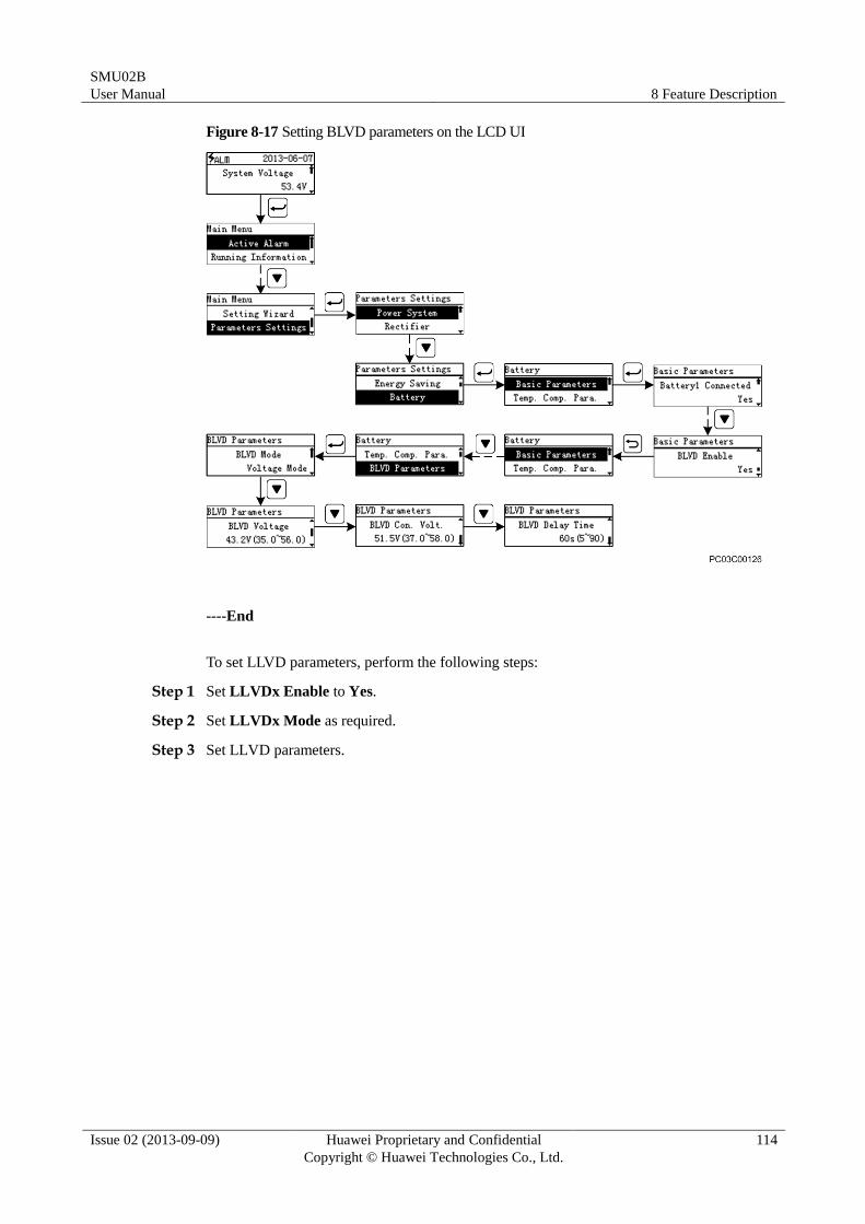
SMU02B
User Manual 8 Feature Description
Issue 02 (2013-09-09) Huawei Proprietary and Confidential
Copyright © Huawei Technologies Co., Ltd.
114
Figure 8-17 Setting BLVD parameters on the LCD UI
----End
To set LLVD parameters, perform the following steps:
Step 1 Set LLVDx Enable to Yes.
Step 2 Set LLVDx Mode as required.
Step 3 Set LLVD parameters.
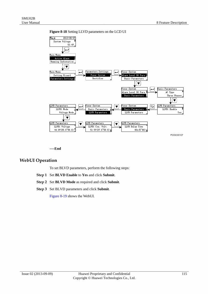
SMU02B
User Manual 8 Feature Description
Issue 02 (2013-09-09) Huawei Proprietary and Confidential
Copyright © Huawei Technologies Co., Ltd.
115
Figure 8-18 Setting LLVD parameters on the LCD UI
----End
WebUI Operation
To set BLVD parameters, perform the following steps:
Step 1 Set BLVD Enable to Yes and click Submit.
Step 2 Set BLVD Mode as required and click Submit.
Step 3 Set BLVD parameters and click Submit.
Figure 8-19 shows the WebUI.
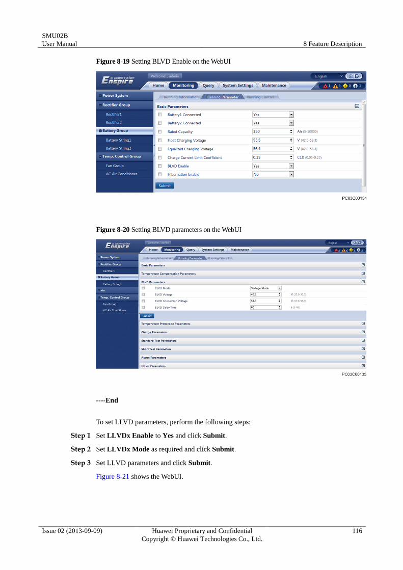
SMU02B
User Manual 8 Feature Description
Issue 02 (2013-09-09) Huawei Proprietary and Confidential
Copyright © Huawei Technologies Co., Ltd.
116
Figure 8-19 Setting BLVD Enable on the WebUI
Figure 8-20 Setting BLVD parameters on the WebUI
----End
To set LLVD parameters, perform the following steps:
Step 1 Set LLVDx Enable to Yes and click Submit.
Step 2 Set LLVDx Mode as required and click Submit.
Step 3 Set LLVD parameters and click Submit.
Figure 8-21 shows the WebUI.
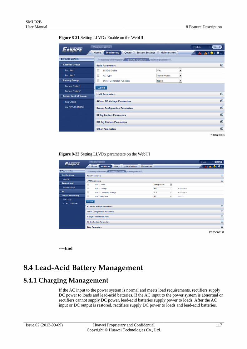
SMU02B
User Manual 8 Feature Description
Issue 02 (2013-09-09) Huawei Proprietary and Confidential
Copyright © Huawei Technologies Co., Ltd.
117
Figure 8-21 Setting LLVDx Enable on the WebUI
Figure 8-22 Setting LLVDx parameters on the WebUI
----End
8.4 Lead-Acid Battery Management
8.4.1 Charging Management
If the AC input to the power system is normal and meets load requirements, rectifiers supply
DC power to loads and lead-acid batteries. If the AC input to the power system is abnormal or
rectifiers cannot supply DC power, lead-acid batteries supply power to loads. After the AC
input or DC output is restored, rectifiers supply DC power to loads and lead-acid batteries.
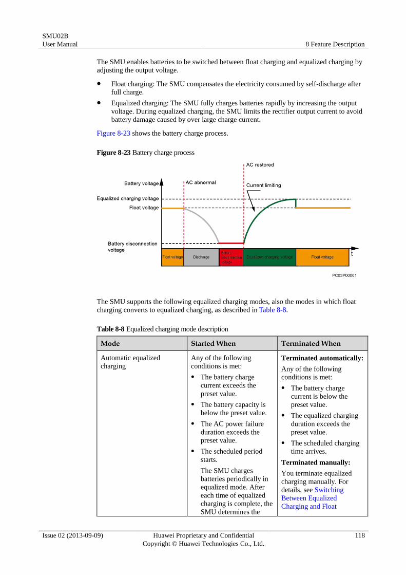
SMU02B
User Manual 8 Feature Description
Issue 02 (2013-09-09) Huawei Proprietary and Confidential
Copyright © Huawei Technologies Co., Ltd.
118
The SMU enables batteries to be switched between float charging and equalized charging by
adjusting the output voltage.
Float charging: The SMU compensates the electricity consumed by self-discharge after
full charge.
Equalized charging: The SMU fully charges batteries rapidly by increasing the output
voltage. During equalized charging, the SMU limits the rectifier output current to avoid
battery damage caused by over large charge current.
Figure 8-23 shows the battery charge process.
Figure 8-23 Battery charge process
The SMU supports the following equalized charging modes, also the modes in which float
charging converts to equalized charging, as described in Table 8-8.
Table 8-8 Equalized charging mode description
Mode Started When Terminated When
Automatic equalized
charging
Any of the following
conditions is met:
The battery charge
current exceeds the
preset value.
The battery capacity is
below the preset value.
The AC power failure
duration exceeds the
preset value.
The scheduled period
starts.
The SMU charges
batteries periodically in
equalized mode. After
each time of equalized
charging is complete, the
SMU determines the
Terminated automatically:
Any of the following
conditions is met:
The battery charge
current is below the
preset value.
The equalized charging
duration exceeds the
preset value.
The scheduled charging
time arrives.
Terminated manually:
You terminate equalized
charging manually. For
details, see Switching
Between Equalized
Charging and Float
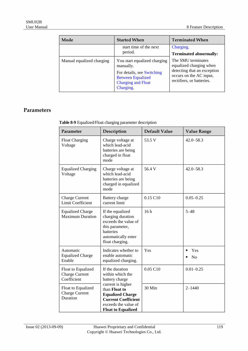
SMU02B
User Manual 8 Feature Description
Issue 02 (2013-09-09) Huawei Proprietary and Confidential
Copyright © Huawei Technologies Co., Ltd.
119
Mode Started When Terminated When
start time of the next
period.
Charging.
Terminated abnormally:
The SMU terminates
equalized charging when
detecting that an exception
occurs on the AC input,
rectifiers, or batteries.
Manual equalized charging You start equalized charging
manually.
For details, see Switching
Between Equalized
Charging and Float
Charging.
Parameters
Table 8-9 Equalized/Float charging parameter description
Parameter Description Default Value Value Range
Float Charging
Voltage
Charge voltage at
which lead-acid
batteries are being
charged in float
mode
53.5 V 42.0–58.3
Equalized Charging
Voltage
Charge voltage at
which lead-acid
batteries are being
charged in equalized
mode
56.4 V 42.0–58.3
Charge Current
Limit Coefficient
Battery charge
current limit
0.15 C10 0.05–0.25
Equalized Charge
Maximum Duration
If the equalized
charging duration
exceeds the value of
this parameter,
batteries
automatically enter
float charging.
16 h 5–48
Automatic
Equalized Charge
Enable
Indicates whether to
enable automatic
equalized charging.
Yes Yes
No
Float to Equalized
Charge Current
Coefficient
If the duration
within which the
battery charge
current is higher
than Float to
Equalized Charge
Current Coefficient exceeds the value of
Float to Equalized
0.05 C10 0.01–0.25
Float to Equalized
Charge Current
Duration
30 Min 2–1440
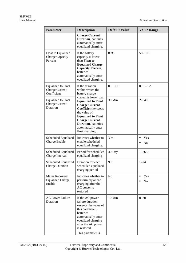
SMU02B
User Manual 8 Feature Description
Issue 02 (2013-09-09) Huawei Proprietary and Confidential
Copyright © Huawei Technologies Co., Ltd.
120
Parameter Description Default Value Value Range
Charge Current
Duration, batteries
automatically enter
equalized charging.
Float to Equalized
Charge Capacity
Percent
If the battery
capacity is lower
than Float to
Equalized Charge Capacity Percent,
batteries
automatically enter
equalized charging.
80% 50–100
Equalized to Float
Charge Current
Coefficient
If the duration
within which the
battery charge
current is lower than
Equalized to Float
Charge Current Coefficient exceeds
the value of
Equalized to Float
Charge Current
Duration, batteries
automatically enter
float charging.
0.01 C10 0.01–0.25
Equalized to Float
Charge Current
Duration
30 Min 2–540
Scheduled Equalized
Charge Enable
Indicates whether to
enable scheduled
equalized charging.
Yes Yes
No
Scheduled Equalized
Charge Interval
Period for scheduled
equalized charging
30 Day 1–365
Scheduled Equalized
Charge Duration
Duration for each
scheduled equalized
charging period
9 h 1–24
Mains Recovery
Equalized Charge
Enable
Indicates whether to
perform equalized
charging after the
AC power is
restored.
No Yes
No
AC Power Failure
Duration
If the AC power
failure duration
exceeds the value of
this parameter,
batteries
automatically enter
equalized charging
after the AC power
is restored.
This parameter is
10 Min 0–30
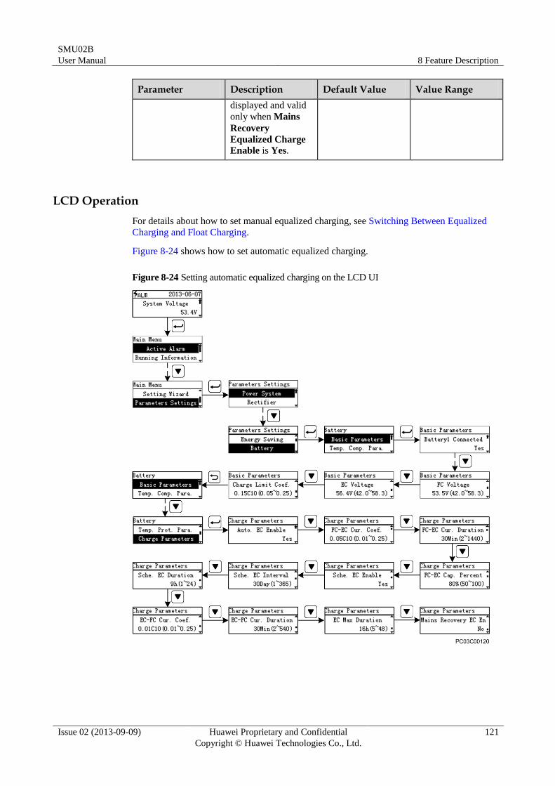
SMU02B
User Manual 8 Feature Description
Issue 02 (2013-09-09) Huawei Proprietary and Confidential
Copyright © Huawei Technologies Co., Ltd.
121
Parameter Description Default Value Value Range
displayed and valid
only when Mains
Recovery
Equalized Charge
Enable is Yes.
LCD Operation
For details about how to set manual equalized charging, see Switching Between Equalized
Charging and Float Charging.
Figure 8-24 shows how to set automatic equalized charging.
Figure 8-24 Setting automatic equalized charging on the LCD UI
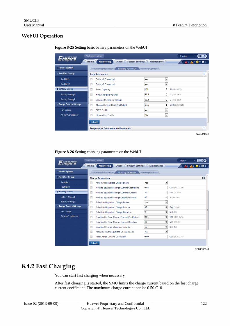
SMU02B
User Manual 8 Feature Description
Issue 02 (2013-09-09) Huawei Proprietary and Confidential
Copyright © Huawei Technologies Co., Ltd.
122
WebUI Operation
Figure 8-25 Setting basic battery parameters on the WebUI
Figure 8-26 Setting charging parameters on the WebUI
8.4.2 Fast Charging
You can start fast charging when necessary.
After fast charging is started, the SMU limits the charge current based on the fast charge current coefficient. The maximum charge current can be 0.50 C10.
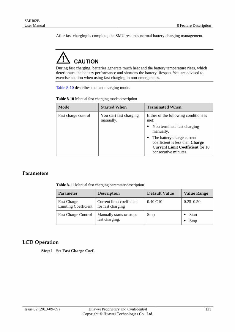
SMU02B
User Manual 8 Feature Description
Issue 02 (2013-09-09) Huawei Proprietary and Confidential
Copyright © Huawei Technologies Co., Ltd.
123
After fast charging is complete, the SMU resumes normal battery charging management.
During fast charging, batteries generate much heat and the battery temperature rises, which
deteriorates the battery performance and shortens the battery lifespan. You are advised to
exercise caution when using fast charging in non-emergencies.
Table 8-10 describes the fast charging mode.
Table 8-10 Manual fast charging mode description
Mode Started When Terminated When
Fast charge control You start fast charging
manually.
Either of the following conditions is
met:
You terminate fast charging
manually.
The battery charge current
coefficient is less than Charge
Current Limit Coefficient for 10
consecutive minutes.
Parameters
Table 8-11 Manual fast charging parameter description
Parameter Description Default Value Value Range
Fast Charge
Limiting Coefficient
Current limit coefficient
for fast charging 0.40 C10 0.25–0.50
Fast Charge Control Manually starts or stops
fast charging.
Stop Start
Stop
LCD Operation
Step 1 Set Fast Charge Coef..

SMU02B
User Manual 8 Feature Description
Issue 02 (2013-09-09) Huawei Proprietary and Confidential
Copyright © Huawei Technologies Co., Ltd.
124
Figure 8-27 Setting Fast Charge Coef. on the LCD UI
Step 2 Start fast charging.
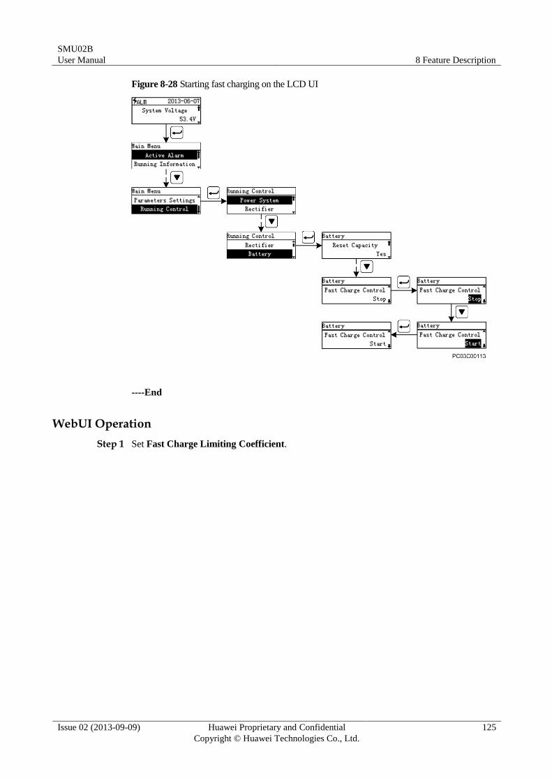
SMU02B
User Manual 8 Feature Description
Issue 02 (2013-09-09) Huawei Proprietary and Confidential
Copyright © Huawei Technologies Co., Ltd.
125
Figure 8-28 Starting fast charging on the LCD UI
----End
WebUI Operation
Step 1 Set Fast Charge Limiting Coefficient.
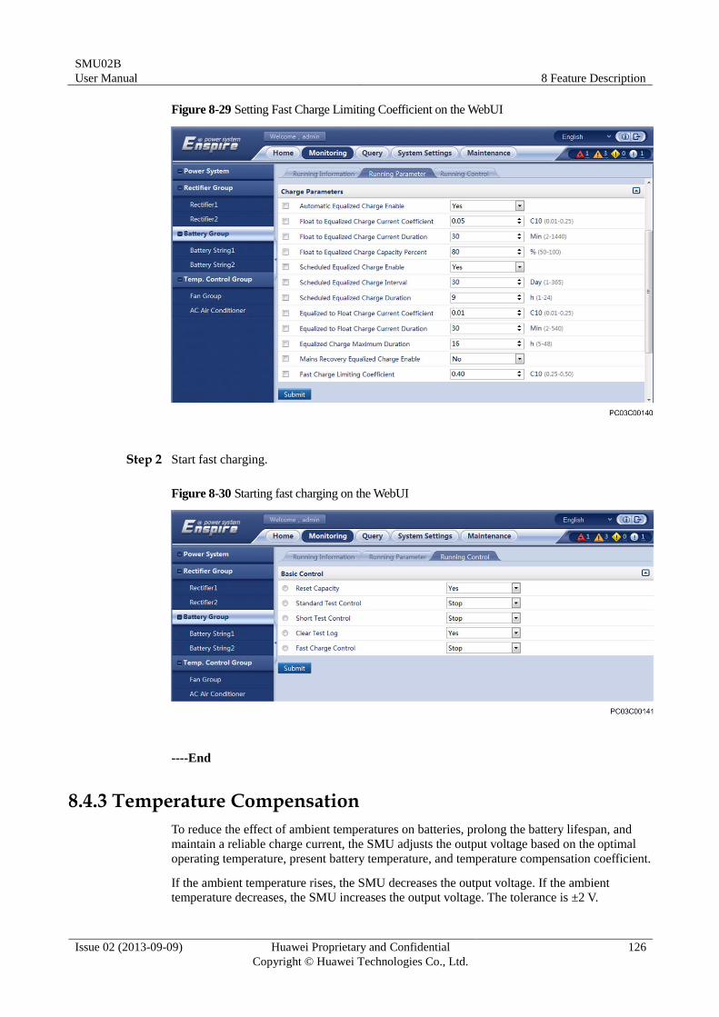
SMU02B
User Manual 8 Feature Description
Issue 02 (2013-09-09) Huawei Proprietary and Confidential
Copyright © Huawei Technologies Co., Ltd.
126
Figure 8-29 Setting Fast Charge Limiting Coefficient on the WebUI
Step 2 Start fast charging.
Figure 8-30 Starting fast charging on the WebUI
----End
8.4.3 Temperature Compensation
To reduce the effect of ambient temperatures on batteries, prolong the battery lifespan, and
maintain a reliable charge current, the SMU adjusts the output voltage based on the optimal
operating temperature, present battery temperature, and temperature compensation coefficient.
If the ambient temperature rises, the SMU decreases the output voltage. If the ambient temperature decreases, the SMU increases the output voltage. The tolerance is ±2 V.
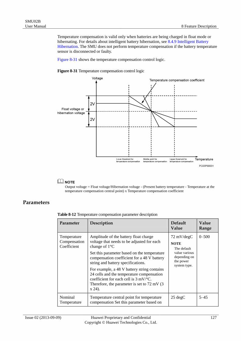
SMU02B
User Manual 8 Feature Description
Issue 02 (2013-09-09) Huawei Proprietary and Confidential
Copyright © Huawei Technologies Co., Ltd.
127
Temperature compensation is valid only when batteries are being charged in float mode or
hibernating. For details about intelligent battery hibernation, see 8.4.9 Intelligent Battery
Hibernation. The SMU does not perform temperature compensation if the battery temperature
sensor is disconnected or faulty.
Figure 8-31 shows the temperature compensation control logic.
Figure 8-31 Temperature compensation control logic
Output voltage = Float voltage/Hibernation voltage - (Present battery temperature - Temperature at the
temperature compensation central point) x Temperature compensation coefficient
Parameters
Table 8-12 Temperature compensation parameter description
Parameter Description Default Value
Value Range
Temperature
Compensation
Coefficient
Amplitude of the battery float charge
voltage that needs to be adjusted for each
change of 1°C
Set this parameter based on the temperature
compensation coefficient for a 48 V battery
string and battery specifications.
For example, a 48 V battery string contains
24 cells and the temperature compensation
coefficient for each cell is 3 mV/°C.
Therefore, the parameter is set to 72 mV (3
x 24).
72 mV/degC
NOTE
The default
value various
depending on
the power
system type.
0–500
Nominal
Temperature
Temperature central point for temperature
compensation Set this parameter based on 25 degC 5–45
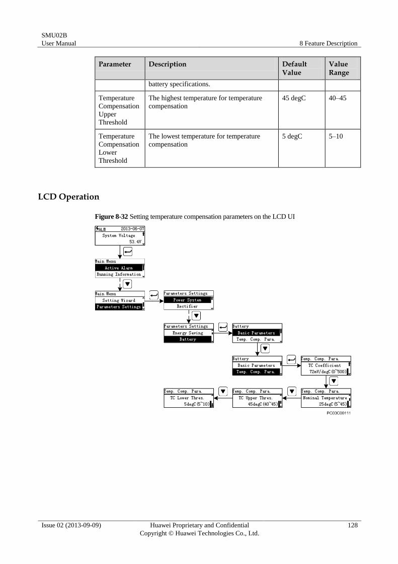
SMU02B
User Manual 8 Feature Description
Issue 02 (2013-09-09) Huawei Proprietary and Confidential
Copyright © Huawei Technologies Co., Ltd.
128
Parameter Description Default Value
Value Range
battery specifications.
Temperature
Compensation
Upper
Threshold
The highest temperature for temperature
compensation
45 degC 40–45
Temperature
Compensation
Lower
Threshold
The lowest temperature for temperature
compensation
5 degC 5–10
LCD Operation
Figure 8-32 Setting temperature compensation parameters on the LCD UI
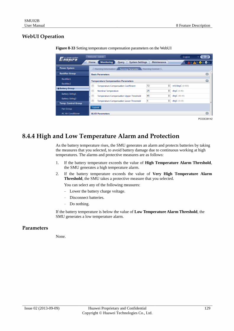
SMU02B
User Manual 8 Feature Description
Issue 02 (2013-09-09) Huawei Proprietary and Confidential
Copyright © Huawei Technologies Co., Ltd.
129
WebUI Operation
Figure 8-33 Setting temperature compensation parameters on the WebUI
8.4.4 High and Low Temperature Alarm and Protection
As the battery temperature rises, the SMU generates an alarm and protects batteries by taking
the measures that you selected, to avoid battery damage due to continuous working at high
temperatures. The alarms and protective measures are as follows:
1. If the battery temperature exceeds the value of High Temperature Alarm Threshold,
the SMU generates a high temperature alarm.
2. If the battery temperature exceeds the value of Very High Temperature Alarm
Threshold, the SMU takes a protective measure that you selected.
You can select any of the following measures:
− Lower the battery charge voltage.
− Disconnect batteries.
− Do nothing.
If the battery temperature is below the value of Low Temperature Alarm Threshold, the
SMU generates a low temperature alarm.
Parameters
None.
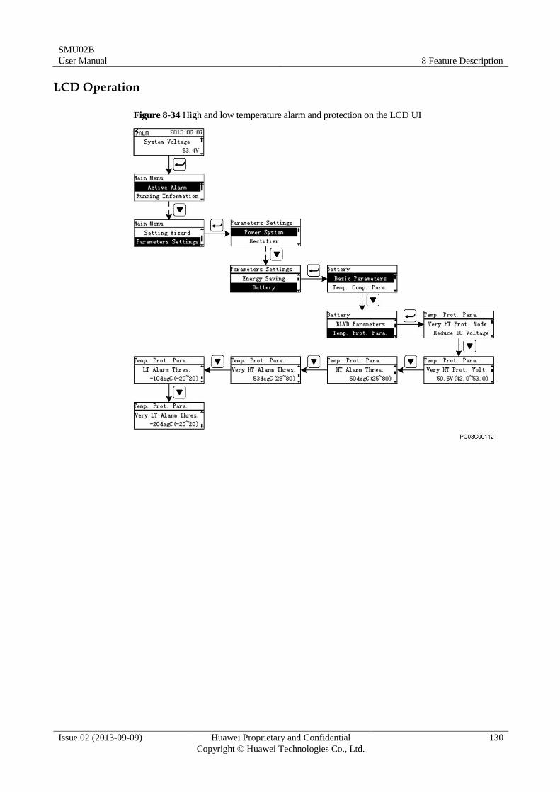
SMU02B
User Manual 8 Feature Description
Issue 02 (2013-09-09) Huawei Proprietary and Confidential
Copyright © Huawei Technologies Co., Ltd.
130
LCD Operation
Figure 8-34 High and low temperature alarm and protection on the LCD UI
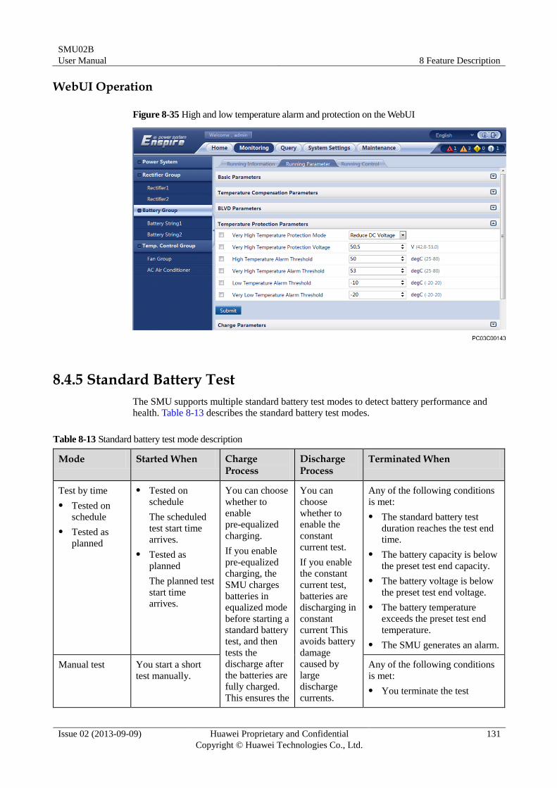
SMU02B
User Manual 8 Feature Description
Issue 02 (2013-09-09) Huawei Proprietary and Confidential
Copyright © Huawei Technologies Co., Ltd.
131
WebUI Operation
Figure 8-35 High and low temperature alarm and protection on the WebUI
8.4.5 Standard Battery Test
The SMU supports multiple standard battery test modes to detect battery performance and
health. Table 8-13 describes the standard battery test modes.
Table 8-13 Standard battery test mode description
Mode Started When Charge Process
Discharge Process
Terminated When
Test by time
Tested on
schedule
Tested as
planned
Tested on
schedule
The scheduled
test start time
arrives.
Tested as
planned
The planned test
start time
arrives.
You can choose
whether to
enable
pre-equalized
charging.
If you enable
pre-equalized
charging, the
SMU charges
batteries in
equalized mode
before starting a
standard battery
test, and then
tests the
discharge after
the batteries are
fully charged.
This ensures the
You can
choose
whether to
enable the
constant
current test.
If you enable
the constant
current test,
batteries are
discharging in
constant
current This
avoids battery
damage
caused by
large
discharge
currents.
Any of the following conditions
is met:
The standard battery test
duration reaches the test end
time.
The battery capacity is below
the preset test end capacity.
The battery voltage is below
the preset test end voltage.
The battery temperature
exceeds the preset test end
temperature.
The SMU generates an alarm.
Manual test You start a short
test manually.
Any of the following conditions
is met:
You terminate the test
SMU02B
User Manual 8 Feature Description
Issue 02 (2013-09-09) Huawei Proprietary and Confidential
Copyright © Huawei Technologies Co., Ltd.
132
Mode Started When Charge Process
Discharge Process
Terminated When
accuracy of
battery test
data.
manually.
The standard battery test
duration reaches the test end
time.
The battery capacity is below
the preset test end capacity.
The battery voltage is below
the preset test end voltage.
The battery temperature
exceeds the preset test end
temperature.
The SMU generates an alarm.
AC power
failure test
An AC power
failure occurs. None Batteries
supply power.
Any of the following conditions
is met:
The AC power is restored.
The standard battery test
duration reaches the test end
time.
The battery capacity is below
the preset test end capacity.
The battery voltage is below
the preset test end voltage.
The battery temperature
exceeds the preset test end
temperature.
The SMU generates an alarm.
The SMU records the standard battery test process in details and generates a test report after
the test ends. You can query the test result over the LCD or WebUI or export it over the
WebUI.
Parameters
Table 8-14 describes the standard battery test parameters. Table 8-15 lists the content in the
battery test report.
Table 8-14 Standard battery test parameter description
Parameter Description Default Value
Value Range
AC Fail Test
Enable
Indicates whether to allow a standard
battery test to be performed when an
AC power failure occurs.
No Yes
No
Time Test Mode The mode in which the SMU starts Disable Disable
SMU02B
User Manual 8 Feature Description
Issue 02 (2013-09-09) Huawei Proprietary and Confidential
Copyright © Huawei Technologies Co., Ltd.
133
Parameter Description Default Value
Value Range
an automatic test periodically or by
time
Planned
Test
Scheduled
Test
Annual Battery
Tests
Number of planned tests within a
year
This parameter is displayed and
valid only when Time Test Mode is
Planned Test.
0 0-6
Planned Test
Time N
Time when a planned test starts
This parameter is displayed and
valid only when Time Test Mode is
Planned Test and the value of
Annual Battery Tests is greater
than or equal to 1.
01-01 00:00 MM-DD
HH:MM
Scheduled Test
Start Time
Time when a scheduled test starts
This parameter is displayed and
valid only when Time Test Mode is
Scheduled Test.
21:00:00 HH:MM:SS
Scheduled Test
Period
Period of a scheduled test
This parameter is displayed and
valid only when Time Test Mode is
Scheduled Test.
90 Day 2–999
Pre-Equalized
Charging Enable
Indicates whether to allow the SMU
to charge batteries in equalized mode
before a standard battery test starts.
Yes Yes
No
Constant Current
Test Enable
Indicates whether to allow batteries
to discharge in constant current in a
standard battery test.
No Yes
No
Constant Test
Current
The current in which batteries
discharge in a standard battery test
This parameter is displayed and
valid only when Constant Current
Test Enable is Yes.
9999 A 1–9999
Test End Voltage If the battery voltage is below the
value of this parameter, the battery
test ends.
46.0 V 44.2–53.0
Test End
Capacity
If the battery capacity is below the
value of this parameter, the battery
test ends.
20% 0–99
Test End
Temperature
If the battery temperature exceeds
the value of this parameter, the
battery test ends.
5 degC -5–15
SMU02B
User Manual 8 Feature Description
Issue 02 (2013-09-09) Huawei Proprietary and Confidential
Copyright © Huawei Technologies Co., Ltd.
134
Parameter Description Default Value
Value Range
Test End Time If the standard battery test duration
reaches the value of this parameter,
the battery test ends.
480 Min 1–6000
Table 8-15 Battery test report parameter description
Parameter Description
Start Time Time when a battery test starts
End Time Time when a battery test ends
Test Type Type of a battery test
Stop Reason Reason why a battery test ends
Test Result Result of a battery test
End Voltage(V) Charge voltage when a battery test ends
Average Discharge Current(A) Average discharge current during a battery test
Discharge Capacity (Ah) Amount of electricity discharged during a battery test
Battery Temperature(degC) Battery temperature when a battery test ends
LCD Operation
The following figure shows how to set standard battery test parameters:
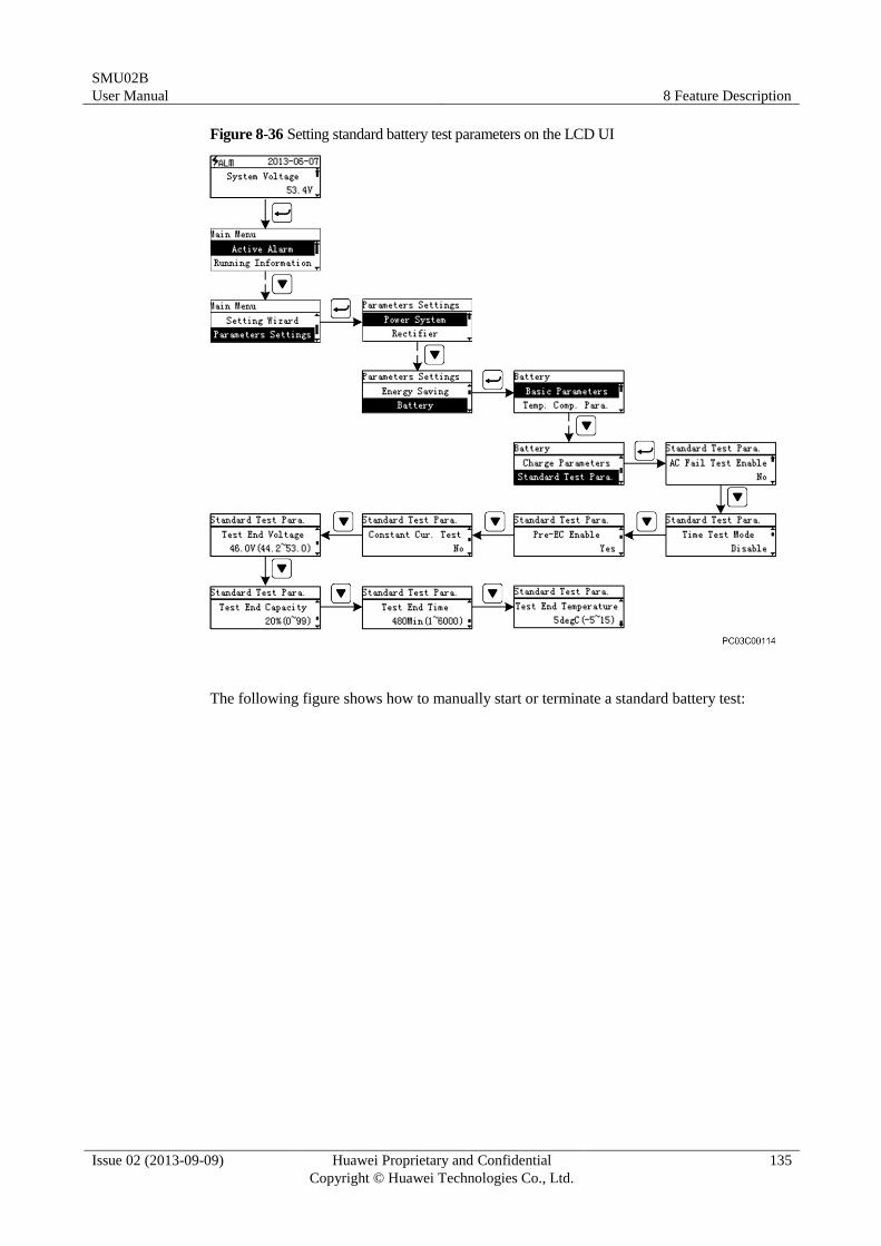
SMU02B
User Manual 8 Feature Description
Issue 02 (2013-09-09) Huawei Proprietary and Confidential
Copyright © Huawei Technologies Co., Ltd.
135
Figure 8-36 Setting standard battery test parameters on the LCD UI
The following figure shows how to manually start or terminate a standard battery test:
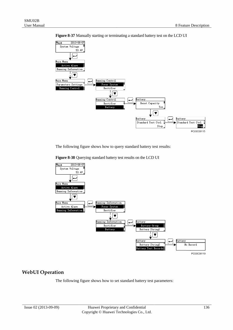
SMU02B
User Manual 8 Feature Description
Issue 02 (2013-09-09) Huawei Proprietary and Confidential
Copyright © Huawei Technologies Co., Ltd.
136
Figure 8-37 Manually starting or terminating a standard battery test on the LCD UI
The following figure shows how to query standard battery test results:
Figure 8-38 Querying standard battery test results on the LCD UI
WebUI Operation
The following figure shows how to set standard battery test parameters:
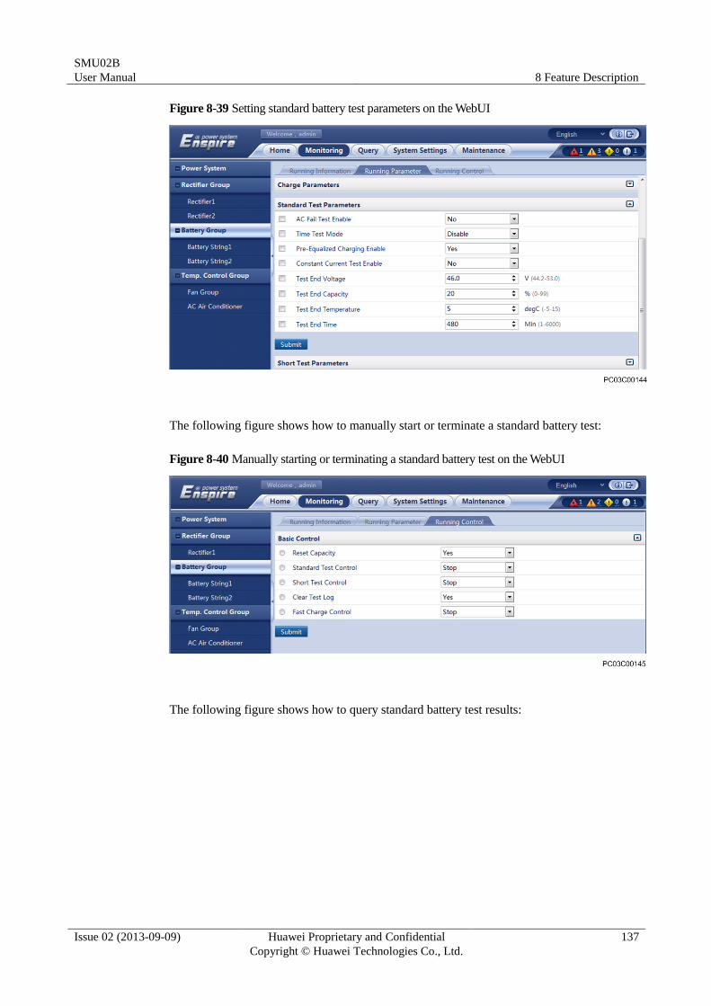
SMU02B
User Manual 8 Feature Description
Issue 02 (2013-09-09) Huawei Proprietary and Confidential
Copyright © Huawei Technologies Co., Ltd.
137
Figure 8-39 Setting standard battery test parameters on the WebUI
The following figure shows how to manually start or terminate a standard battery test:
Figure 8-40 Manually starting or terminating a standard battery test on the WebUI
The following figure shows how to query standard battery test results:
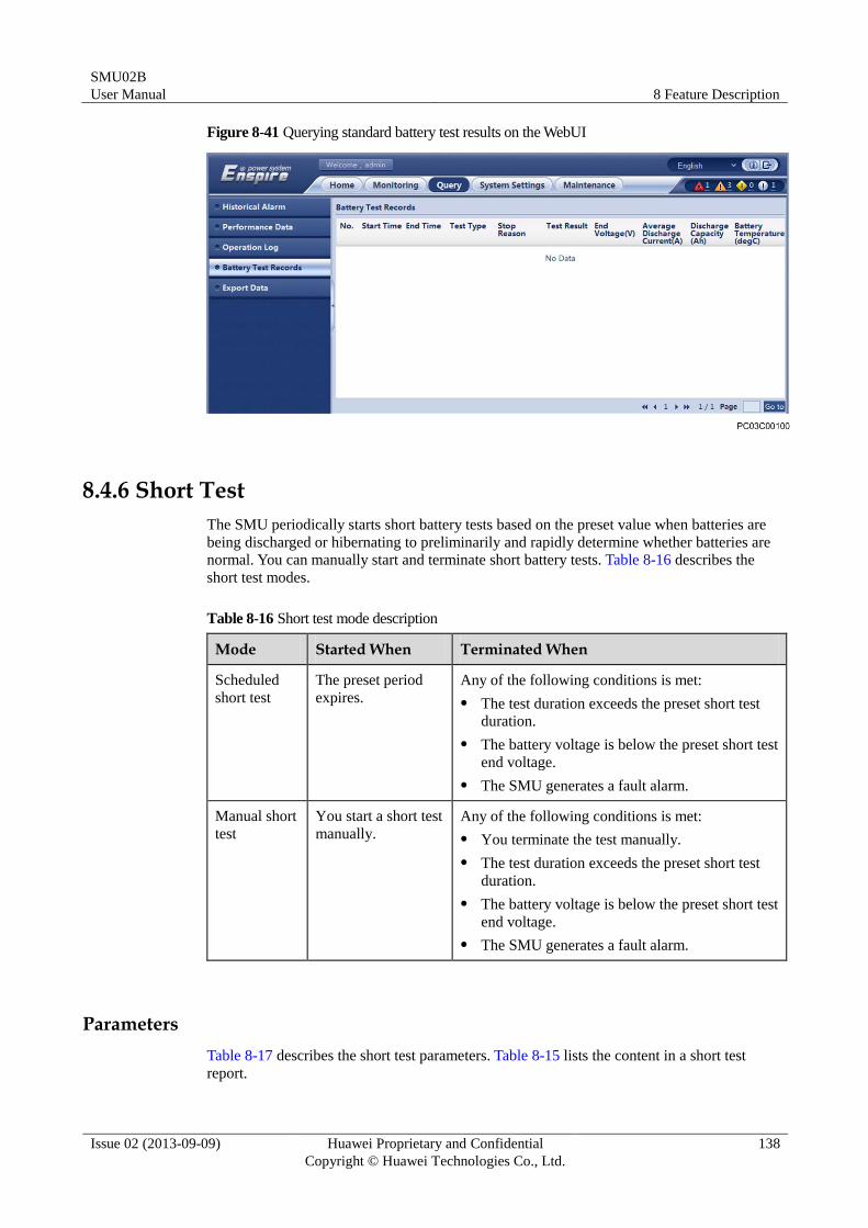
SMU02B
User Manual 8 Feature Description
Issue 02 (2013-09-09) Huawei Proprietary and Confidential
Copyright © Huawei Technologies Co., Ltd.
138
Figure 8-41 Querying standard battery test results on the WebUI
8.4.6 Short Test
The SMU periodically starts short battery tests based on the preset value when batteries are
being discharged or hibernating to preliminarily and rapidly determine whether batteries are
normal. You can manually start and terminate short battery tests. Table 8-16 describes the
short test modes.
Table 8-16 Short test mode description
Mode Started When Terminated When
Scheduled
short test
The preset period
expires.
Any of the following conditions is met:
The test duration exceeds the preset short test
duration.
The battery voltage is below the preset short test
end voltage.
The SMU generates a fault alarm.
Manual short
test
You start a short test
manually.
Any of the following conditions is met:
You terminate the test manually.
The test duration exceeds the preset short test
duration.
The battery voltage is below the preset short test
end voltage.
The SMU generates a fault alarm.
Parameters
Table 8-17 describes the short test parameters. Table 8-15 lists the content in a short test
report.
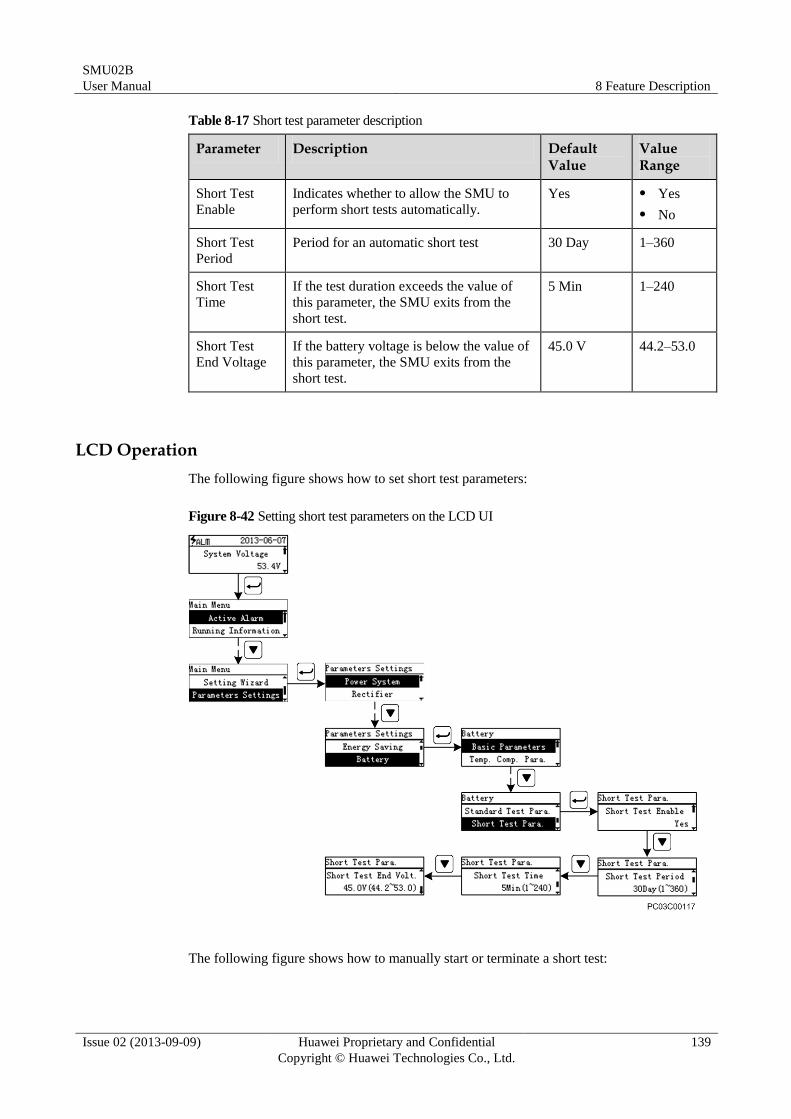
SMU02B
User Manual 8 Feature Description
Issue 02 (2013-09-09) Huawei Proprietary and Confidential
Copyright © Huawei Technologies Co., Ltd.
139
Table 8-17 Short test parameter description
Parameter Description Default Value
Value Range
Short Test
Enable
Indicates whether to allow the SMU to
perform short tests automatically.
Yes Yes
No
Short Test
Period
Period for an automatic short test 30 Day 1–360
Short Test
Time
If the test duration exceeds the value of
this parameter, the SMU exits from the
short test.
5 Min 1–240
Short Test
End Voltage
If the battery voltage is below the value of
this parameter, the SMU exits from the
short test.
45.0 V 44.2–53.0
LCD Operation
The following figure shows how to set short test parameters:
Figure 8-42 Setting short test parameters on the LCD UI
The following figure shows how to manually start or terminate a short test:
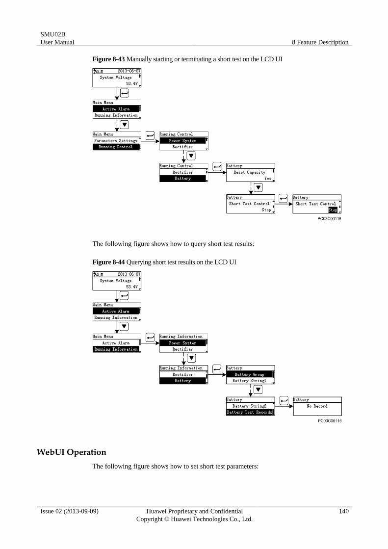
SMU02B
User Manual 8 Feature Description
Issue 02 (2013-09-09) Huawei Proprietary and Confidential
Copyright © Huawei Technologies Co., Ltd.
140
Figure 8-43 Manually starting or terminating a short test on the LCD UI
The following figure shows how to query short test results:
Figure 8-44 Querying short test results on the LCD UI
WebUI Operation
The following figure shows how to set short test parameters:
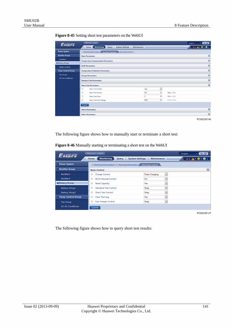
SMU02B
User Manual 8 Feature Description
Issue 02 (2013-09-09) Huawei Proprietary and Confidential
Copyright © Huawei Technologies Co., Ltd.
141
Figure 8-45 Setting short test parameters on the WebUI
The following figure shows how to manually start or terminate a short test:
Figure 8-46 Manually starting or terminating a short test on the WebUI
The following figure shows how to query short test results:

SMU02B
User Manual 8 Feature Description
Issue 02 (2013-09-09) Huawei Proprietary and Confidential
Copyright © Huawei Technologies Co., Ltd.
142
Figure 8-47 Querying short test results on the WebUI
8.4.7 Presence and Balance Detection
The SMU detects battery presence and balance from the following aspects:
Presence
Middle point voltage balance
Balance of each battery
Current balance
Presence Detection
The SMU checks whether batteries are present by using a signal cable for monitoring battery
middle point voltages. If a battery is stolen, the SMU generates a Battery Not Detected alarm,
reminding users of taking measures immediately.
The number of battery strings to be detected depends on the power system type. The SMU
detects the presence of a maximum of six battery strings.
Figure 8-48 shows the hardware connections. Table 8-18 describes the parameters.
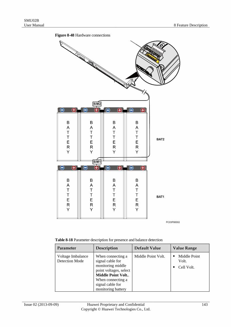
SMU02B
User Manual 8 Feature Description
Issue 02 (2013-09-09) Huawei Proprietary and Confidential
Copyright © Huawei Technologies Co., Ltd.
143
Figure 8-48 Hardware connections
Table 8-18 Parameter description for presence and balance detection
Parameter Description Default Value Value Range
Voltage Imbalance
Detection Mode
When connecting a
signal cable for
monitoring middle
point voltages, select
Middle Point Volt..
When connecting a
signal cable for
monitoring battery
Middle Point Volt. Middle Point
Volt.
Cell Volt.
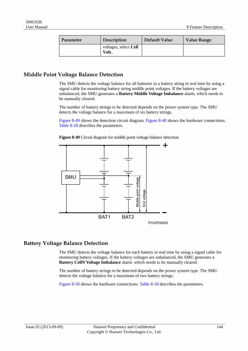
SMU02B
User Manual 8 Feature Description
Issue 02 (2013-09-09) Huawei Proprietary and Confidential
Copyright © Huawei Technologies Co., Ltd.
144
Parameter Description Default Value Value Range
voltages, select Cell
Volt..
Middle Point Voltage Balance Detection
The SMU detects the voltage balance for all batteries in a battery string in real time by using a
signal cable for monitoring battery string middle point voltages. If the battery voltages are
unbalanced, the SMU generates a Battery Middle Voltage Imbalance alarm, which needs to
be manually cleared.
The number of battery strings to be detected depends on the power system type. The SMU
detects the voltage balance for a maximum of six battery strings.
Figure 8-49 shows the detection circuit diagram. Figure 8-48 shows the hardware connections.
Table 8-18 describes the parameters.
Figure 8-49 Circuit diagram for middle point voltage balance detection
Battery Voltage Balance Detection
The SMU detects the voltage balance for each battery in real time by using a signal cable for
monitoring battery voltages. If the battery voltages are unbalanced, the SMU generates a
Battery CellN Voltage Imbalance alarm. which needs to be manually cleared.
The number of battery strings to be detected depends on the power system type. The SMU
detects the voltage balance for a maximum of two battery strings.
Figure 8-50 shows the hardware connections. Table 8-18 describes the parameters.
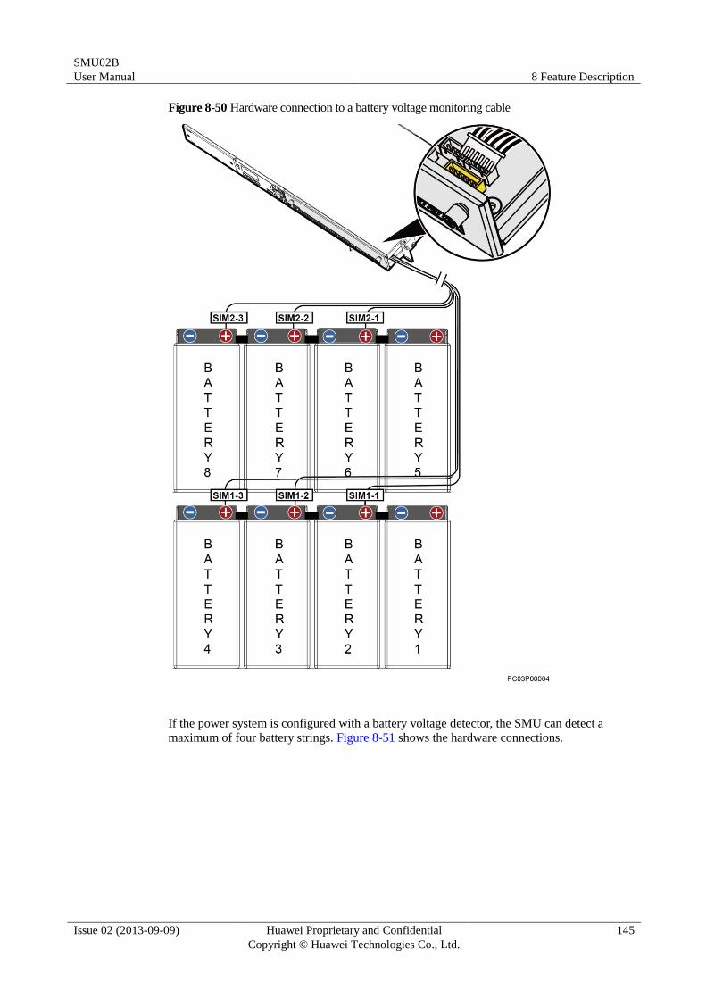
SMU02B
User Manual 8 Feature Description
Issue 02 (2013-09-09) Huawei Proprietary and Confidential
Copyright © Huawei Technologies Co., Ltd.
145
Figure 8-50 Hardware connection to a battery voltage monitoring cable
If the power system is configured with a battery voltage detector, the SMU can detect a
maximum of four battery strings. Figure 8-51 shows the hardware connections.
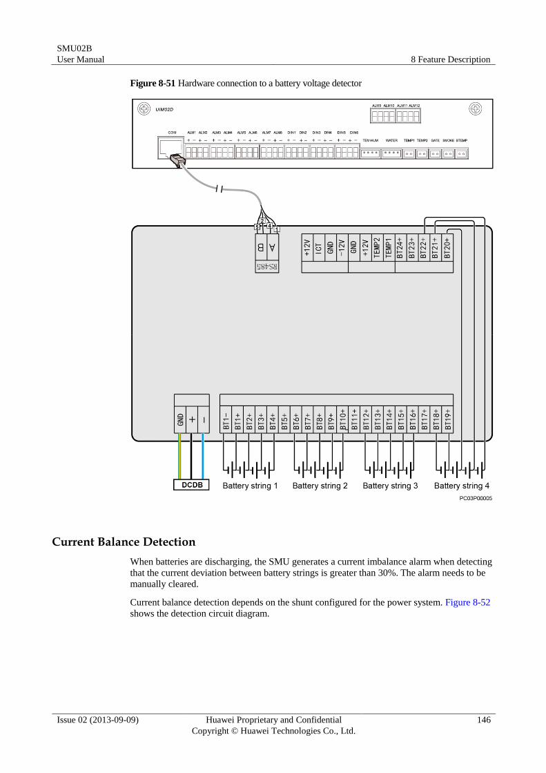
SMU02B
User Manual 8 Feature Description
Issue 02 (2013-09-09) Huawei Proprietary and Confidential
Copyright © Huawei Technologies Co., Ltd.
146
Figure 8-51 Hardware connection to a battery voltage detector
Current Balance Detection
When batteries are discharging, the SMU generates a current imbalance alarm when detecting
that the current deviation between battery strings is greater than 30%. The alarm needs to be
manually cleared.
Current balance detection depends on the shunt configured for the power system. Figure 8-52
shows the detection circuit diagram.
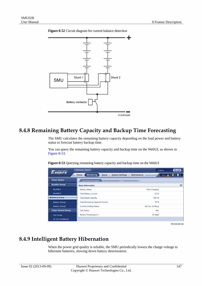
SMU02B
User Manual 8 Feature Description
Issue 02 (2013-09-09) Huawei Proprietary and Confidential
Copyright © Huawei Technologies Co., Ltd.
147
Figure 8-52 Circuit diagram for current balance detection
8.4.8 Remaining Battery Capacity and Backup Time Forecasting
The SMU calculates the remaining battery capacity depending on the load power and battery
status to forecast battery backup time.
You can query the remaining battery capacity and backup time on the WebUI, as shown in
Figure 8-53.
Figure 8-53 Querying remaining battery capacity and backup time on the WebUI
8.4.9 Intelligent Battery Hibernation
When the power grid quality is reliable, the SMU periodically lowers the charge voltage to hibernate batteries, slowing down battery deterioration.
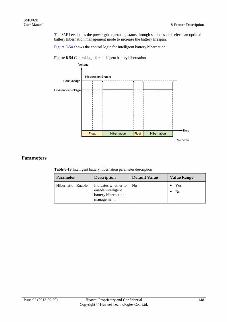
SMU02B
User Manual 8 Feature Description
Issue 02 (2013-09-09) Huawei Proprietary and Confidential
Copyright © Huawei Technologies Co., Ltd.
148
The SMU evaluates the power grid operating status through statistics and selects an optimal
battery hibernation management mode to increase the battery lifespan.
Figure 8-54 shows the control logic for intelligent battery hibernation.
Figure 8-54 Control logic for intelligent battery hibernation
Parameters
Table 8-19 Intelligent battery hibernation parameter description
Parameter Description Default Value Value Range
Hibernation Enable Indicates whether to
enable intelligent
battery hibernation
management.
No Yes
No
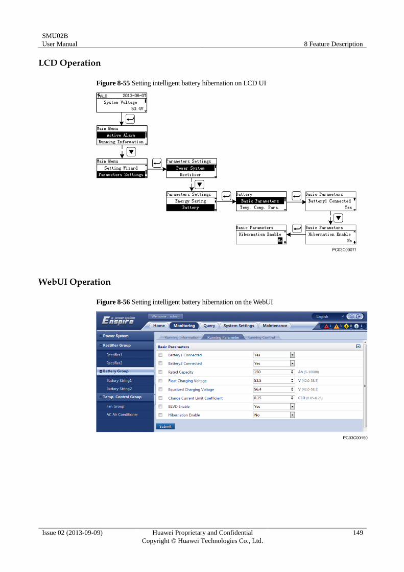
SMU02B
User Manual 8 Feature Description
Issue 02 (2013-09-09) Huawei Proprietary and Confidential
Copyright © Huawei Technologies Co., Ltd.
149
LCD Operation
Figure 8-55 Setting intelligent battery hibernation on LCD UI
WebUI Operation
Figure 8-56 Setting intelligent battery hibernation on the WebUI
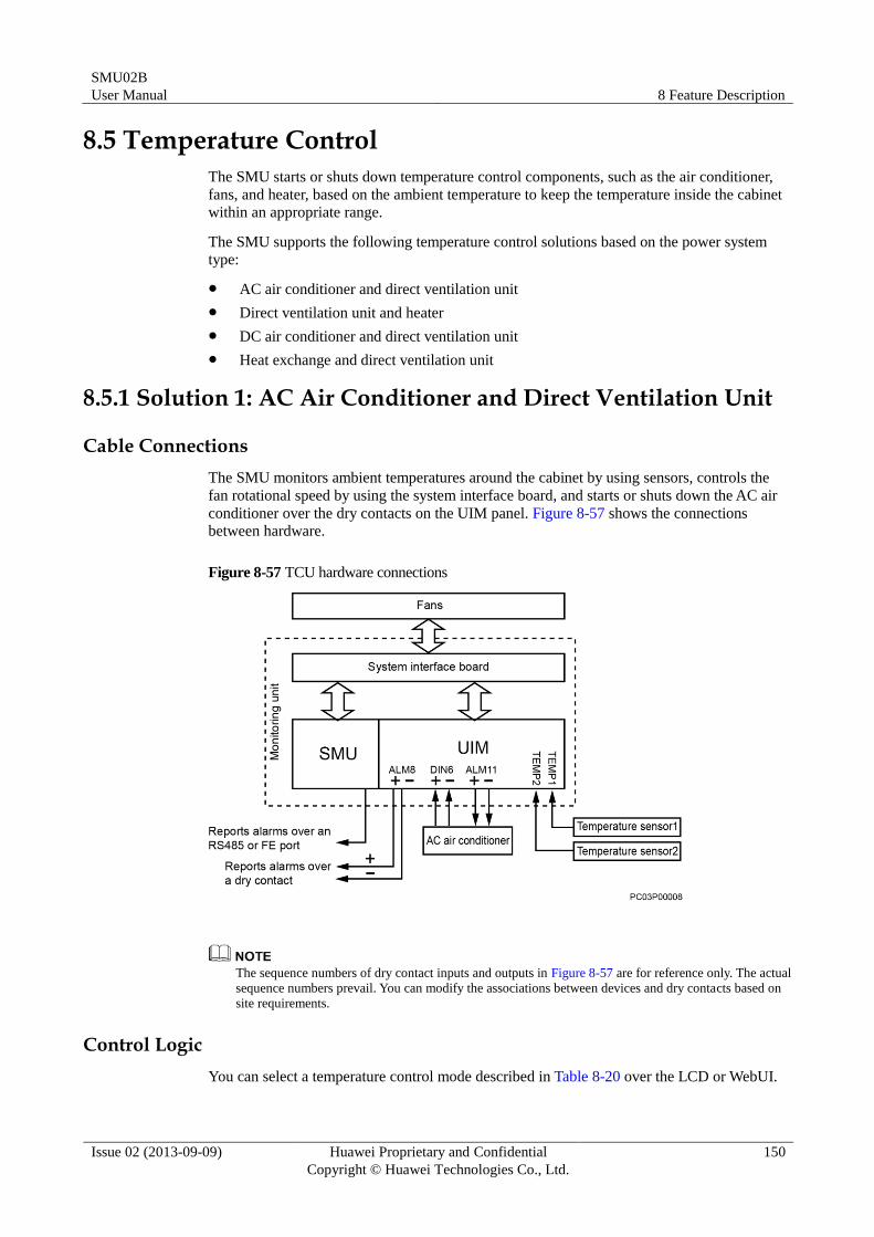
SMU02B
User Manual 8 Feature Description
Issue 02 (2013-09-09) Huawei Proprietary and Confidential
Copyright © Huawei Technologies Co., Ltd.
150
8.5 Temperature Control
The SMU starts or shuts down temperature control components, such as the air conditioner,
fans, and heater, based on the ambient temperature to keep the temperature inside the cabinet
within an appropriate range.
The SMU supports the following temperature control solutions based on the power system
type:
AC air conditioner and direct ventilation unit
Direct ventilation unit and heater
DC air conditioner and direct ventilation unit
Heat exchange and direct ventilation unit
8.5.1 Solution 1: AC Air Conditioner and Direct Ventilation Unit
Cable Connections
The SMU monitors ambient temperatures around the cabinet by using sensors, controls the
fan rotational speed by using the system interface board, and starts or shuts down the AC air
conditioner over the dry contacts on the UIM panel. Figure 8-57 shows the connections
between hardware.
Figure 8-57 TCU hardware connections
The sequence numbers of dry contact inputs and outputs in Figure 8-57 are for reference only. The actual
sequence numbers prevail. You can modify the associations between devices and dry contacts based on
site requirements.
Control Logic
You can select a temperature control mode described in Table 8-20 over the LCD or WebUI.
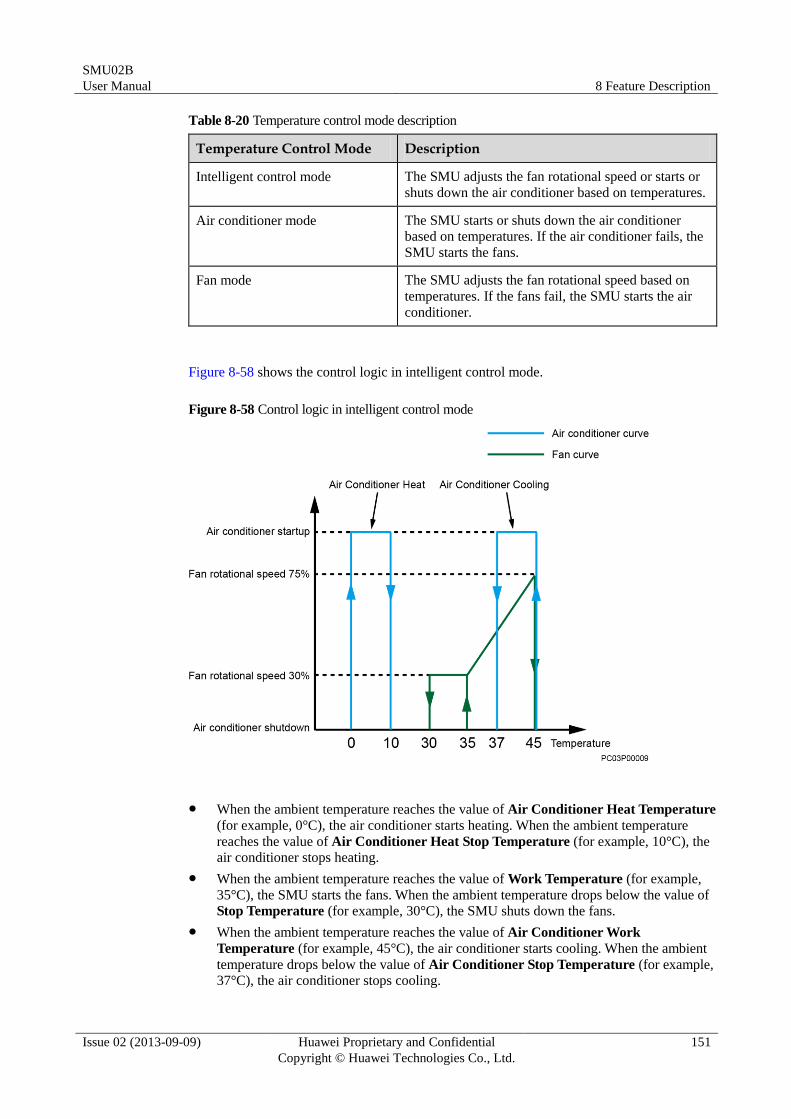
SMU02B
User Manual 8 Feature Description
Issue 02 (2013-09-09) Huawei Proprietary and Confidential
Copyright © Huawei Technologies Co., Ltd.
151
Table 8-20 Temperature control mode description
Temperature Control Mode Description
Intelligent control mode The SMU adjusts the fan rotational speed or starts or
shuts down the air conditioner based on temperatures.
Air conditioner mode The SMU starts or shuts down the air conditioner
based on temperatures. If the air conditioner fails, the
SMU starts the fans.
Fan mode The SMU adjusts the fan rotational speed based on
temperatures. If the fans fail, the SMU starts the air
conditioner.
Figure 8-58 shows the control logic in intelligent control mode.
Figure 8-58 Control logic in intelligent control mode
When the ambient temperature reaches the value of Air Conditioner Heat Temperature
(for example, 0°C), the air conditioner starts heating. When the ambient temperature
reaches the value of Air Conditioner Heat Stop Temperature (for example, 10°C), the
air conditioner stops heating.
When the ambient temperature reaches the value of Work Temperature (for example,
35°C), the SMU starts the fans. When the ambient temperature drops below the value of
Stop Temperature (for example, 30°C), the SMU shuts down the fans.
When the ambient temperature reaches the value of Air Conditioner Work
Temperature (for example, 45°C), the air conditioner starts cooling. When the ambient
temperature drops below the value of Air Conditioner Stop Temperature (for example,
37°C), the air conditioner stops cooling.
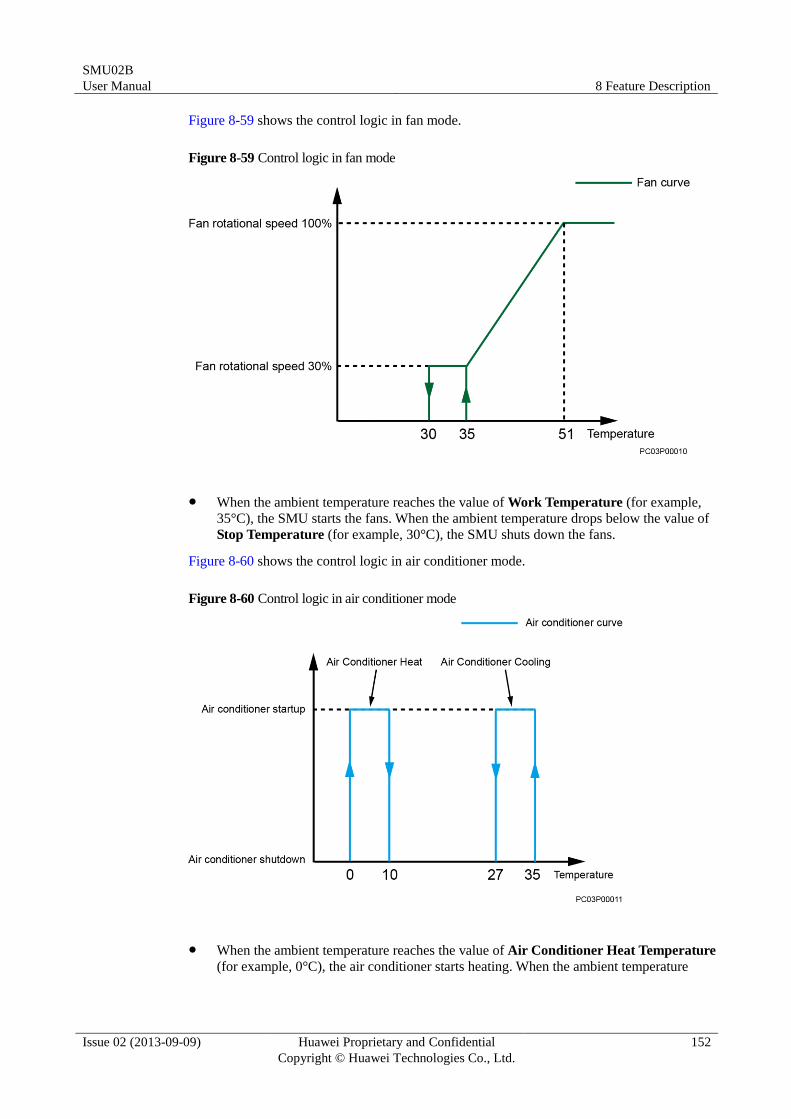
SMU02B
User Manual 8 Feature Description
Issue 02 (2013-09-09) Huawei Proprietary and Confidential
Copyright © Huawei Technologies Co., Ltd.
152
Figure 8-59 shows the control logic in fan mode.
Figure 8-59 Control logic in fan mode
When the ambient temperature reaches the value of Work Temperature (for example,
35°C), the SMU starts the fans. When the ambient temperature drops below the value of
Stop Temperature (for example, 30°C), the SMU shuts down the fans.
Figure 8-60 shows the control logic in air conditioner mode.
Figure 8-60 Control logic in air conditioner mode
When the ambient temperature reaches the value of Air Conditioner Heat Temperature
(for example, 0°C), the air conditioner starts heating. When the ambient temperature
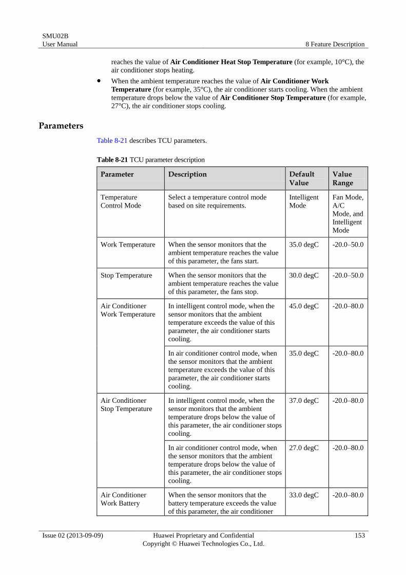
SMU02B
User Manual 8 Feature Description
Issue 02 (2013-09-09) Huawei Proprietary and Confidential
Copyright © Huawei Technologies Co., Ltd.
153
reaches the value of Air Conditioner Heat Stop Temperature (for example, 10°C), the
air conditioner stops heating.
When the ambient temperature reaches the value of Air Conditioner Work
Temperature (for example, 35°C), the air conditioner starts cooling. When the ambient
temperature drops below the value of Air Conditioner Stop Temperature (for example,
27°C), the air conditioner stops cooling.
Parameters
Table 8-21 describes TCU parameters.
Table 8-21 TCU parameter description
Parameter Description Default Value
Value Range
Temperature
Control Mode
Select a temperature control mode
based on site requirements.
Intelligent
Mode
Fan Mode,
A/C
Mode, and
Intelligent
Mode
Work Temperature When the sensor monitors that the
ambient temperature reaches the value
of this parameter, the fans start.
35.0 degC -20.0–50.0
Stop Temperature When the sensor monitors that the
ambient temperature reaches the value
of this parameter, the fans stop.
30.0 degC -20.0–50.0
Air Conditioner
Work Temperature
In intelligent control mode, when the
sensor monitors that the ambient
temperature exceeds the value of this
parameter, the air conditioner starts
cooling.
45.0 degC -20.0–80.0
In air conditioner control mode, when
the sensor monitors that the ambient
temperature exceeds the value of this
parameter, the air conditioner starts
cooling.
35.0 degC -20.0–80.0
Air Conditioner
Stop Temperature
In intelligent control mode, when the
sensor monitors that the ambient
temperature drops below the value of
this parameter, the air conditioner stops
cooling.
37.0 degC -20.0–80.0
In air conditioner control mode, when
the sensor monitors that the ambient
temperature drops below the value of
this parameter, the air conditioner stops
cooling.
27.0 degC -20.0–80.0
Air Conditioner
Work Battery
When the sensor monitors that the
battery temperature exceeds the value of this parameter, the air conditioner
33.0 degC -20.0–80.0
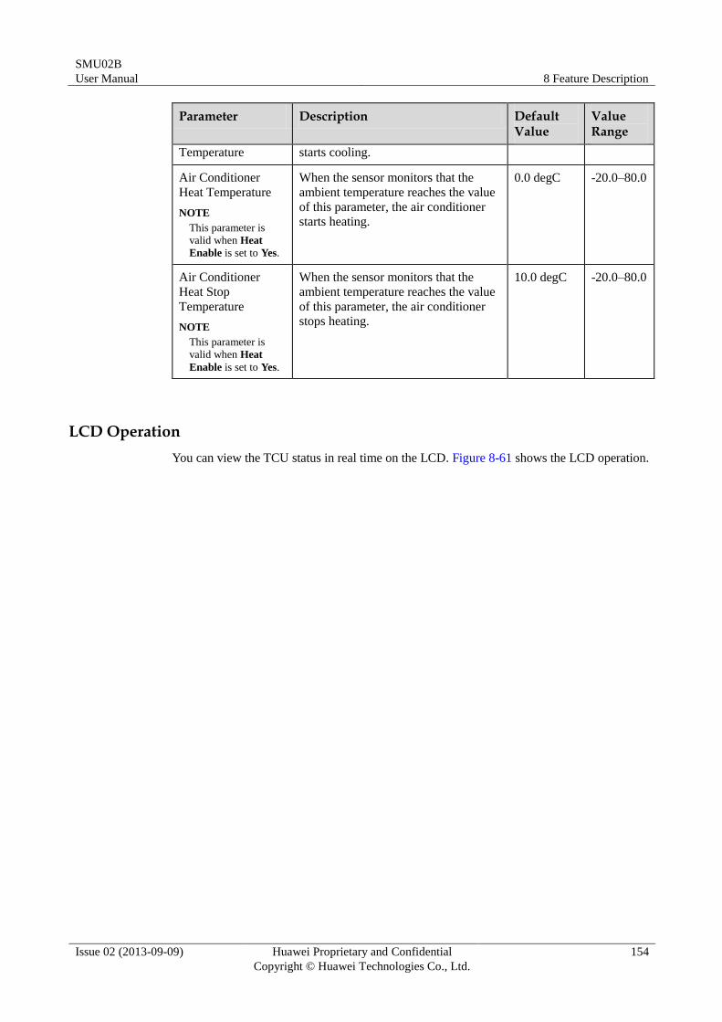
SMU02B
User Manual 8 Feature Description
Issue 02 (2013-09-09) Huawei Proprietary and Confidential
Copyright © Huawei Technologies Co., Ltd.
154
Parameter Description Default Value
Value Range
Temperature starts cooling.
Air Conditioner
Heat Temperature
NOTE
This parameter is
valid when Heat
Enable is set to Yes.
When the sensor monitors that the
ambient temperature reaches the value
of this parameter, the air conditioner
starts heating.
0.0 degC -20.0–80.0
Air Conditioner
Heat Stop
Temperature
NOTE
This parameter is
valid when Heat
Enable is set to Yes.
When the sensor monitors that the
ambient temperature reaches the value
of this parameter, the air conditioner
stops heating.
10.0 degC -20.0–80.0
LCD Operation
You can view the TCU status in real time on the LCD. Figure 8-61 shows the LCD operation.
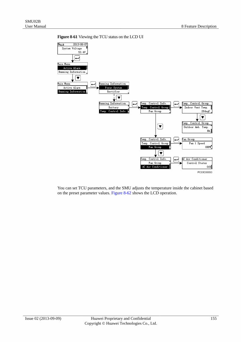
SMU02B
User Manual 8 Feature Description
Issue 02 (2013-09-09) Huawei Proprietary and Confidential
Copyright © Huawei Technologies Co., Ltd.
155
Figure 8-61 Viewing the TCU status on the LCD UI
You can set TCU parameters, and the SMU adjusts the temperature inside the cabinet based
on the preset parameter values. Figure 8-62 shows the LCD operation.
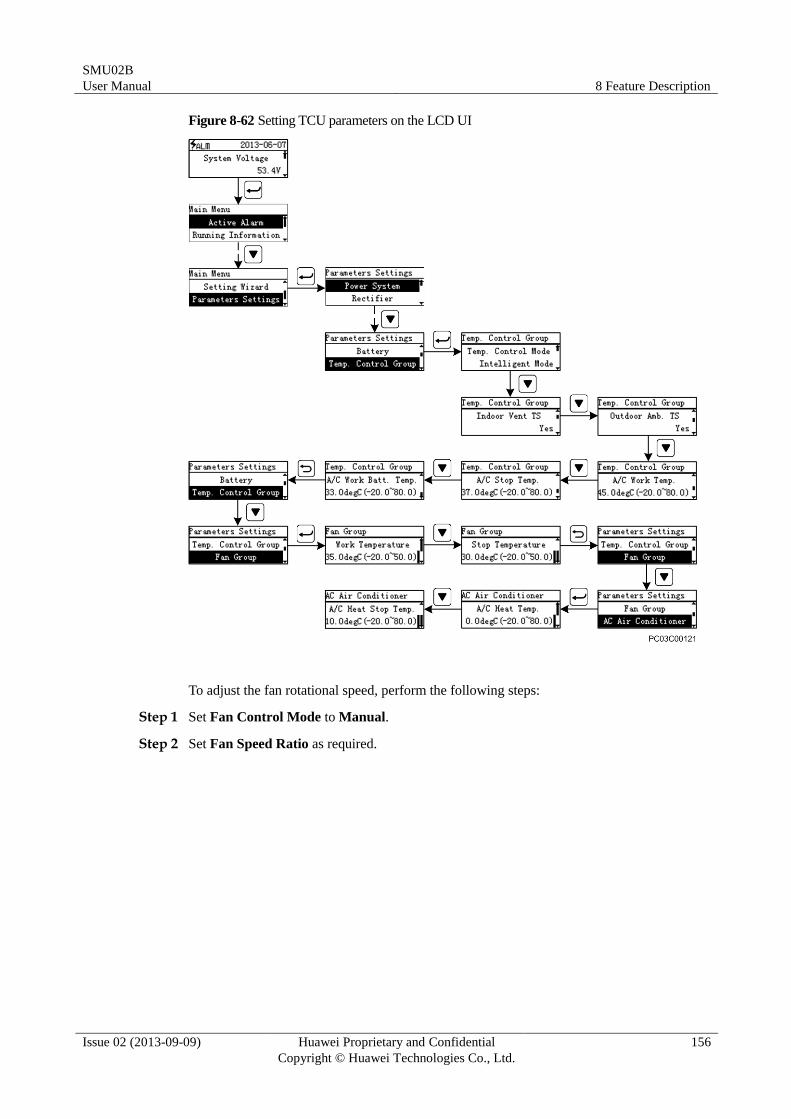
SMU02B
User Manual 8 Feature Description
Issue 02 (2013-09-09) Huawei Proprietary and Confidential
Copyright © Huawei Technologies Co., Ltd.
156
Figure 8-62 Setting TCU parameters on the LCD UI
To adjust the fan rotational speed, perform the following steps:
Step 1 Set Fan Control Mode to Manual.
Step 2 Set Fan Speed Ratio as required.
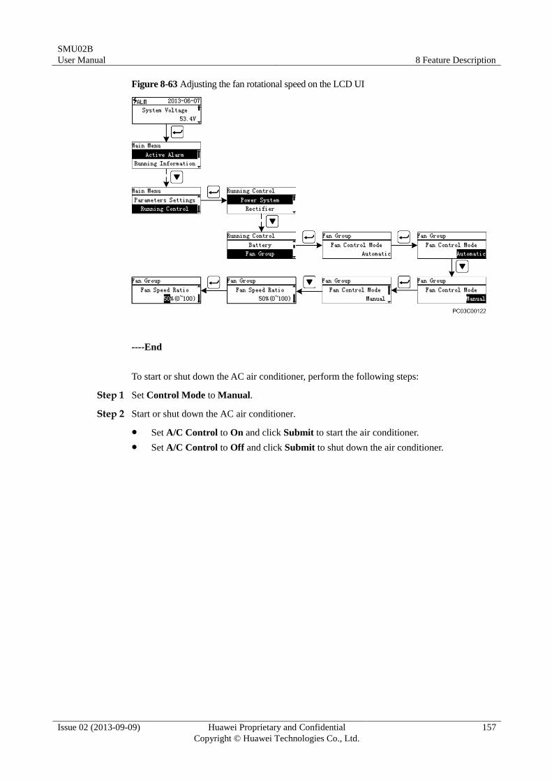
SMU02B
User Manual 8 Feature Description
Issue 02 (2013-09-09) Huawei Proprietary and Confidential
Copyright © Huawei Technologies Co., Ltd.
157
Figure 8-63 Adjusting the fan rotational speed on the LCD UI
----End
To start or shut down the AC air conditioner, perform the following steps:
Step 1 Set Control Mode to Manual.
Step 2 Start or shut down the AC air conditioner.
Set A/C Control to On and click Submit to start the air conditioner.
Set A/C Control to Off and click Submit to shut down the air conditioner.
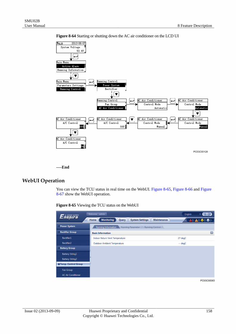
SMU02B
User Manual 8 Feature Description
Issue 02 (2013-09-09) Huawei Proprietary and Confidential
Copyright © Huawei Technologies Co., Ltd.
158
Figure 8-64 Starting or shutting down the AC air conditioner on the LCD UI
----End
WebUI Operation
You can view the TCU status in real time on the WebUI. Figure 8-65, Figure 8-66 and Figure
8-67 show the WebUI operation.
Figure 8-65 Viewing the TCU status on the WebUI
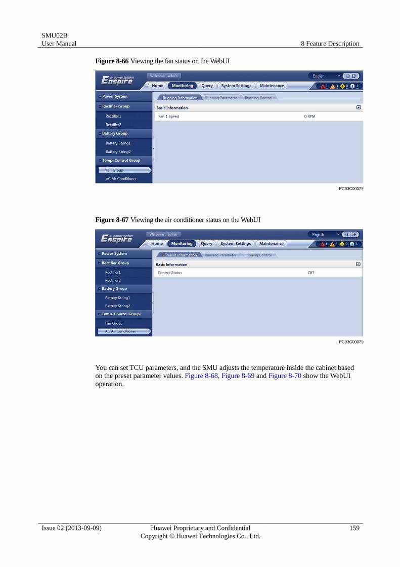
SMU02B
User Manual 8 Feature Description
Issue 02 (2013-09-09) Huawei Proprietary and Confidential
Copyright © Huawei Technologies Co., Ltd.
159
Figure 8-66 Viewing the fan status on the WebUI
Figure 8-67 Viewing the air conditioner status on the WebUI
You can set TCU parameters, and the SMU adjusts the temperature inside the cabinet based
on the preset parameter values. Figure 8-68, Figure 8-69 and Figure 8-70 show the WebUI
operation.
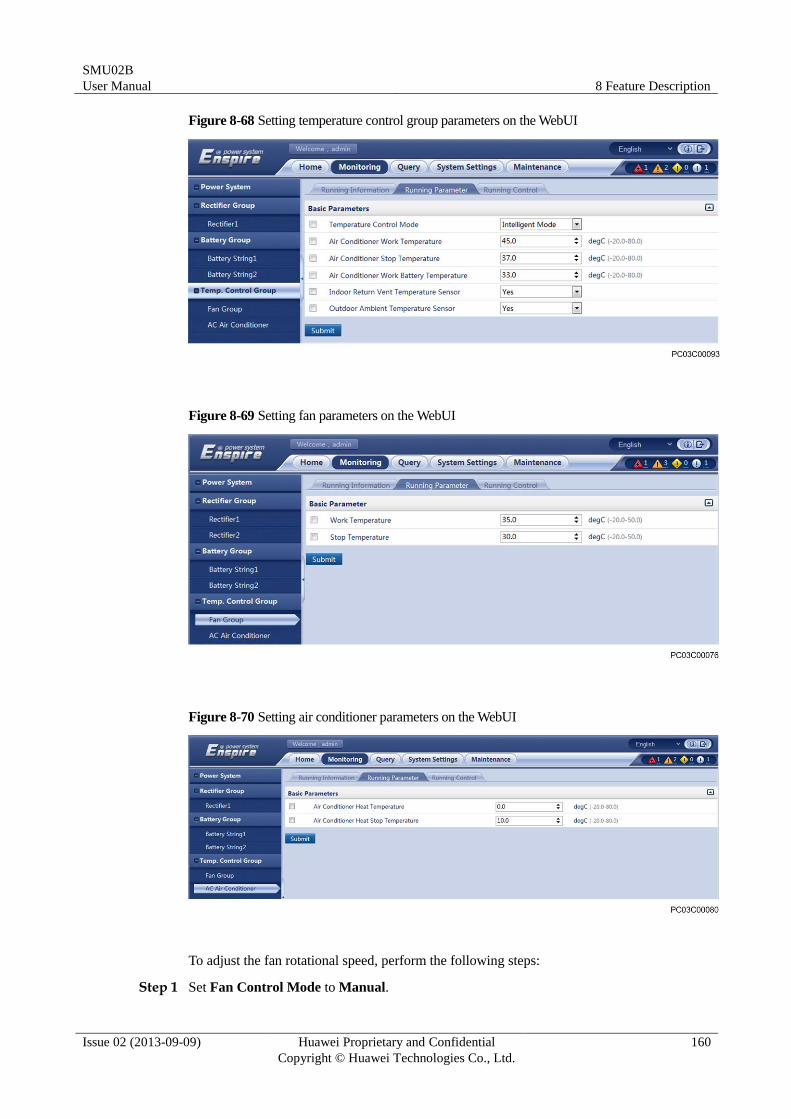
SMU02B
User Manual 8 Feature Description
Issue 02 (2013-09-09) Huawei Proprietary and Confidential
Copyright © Huawei Technologies Co., Ltd.
160
Figure 8-68 Setting temperature control group parameters on the WebUI
Figure 8-69 Setting fan parameters on the WebUI
Figure 8-70 Setting air conditioner parameters on the WebUI
To adjust the fan rotational speed, perform the following steps:
Step 1 Set Fan Control Mode to Manual.
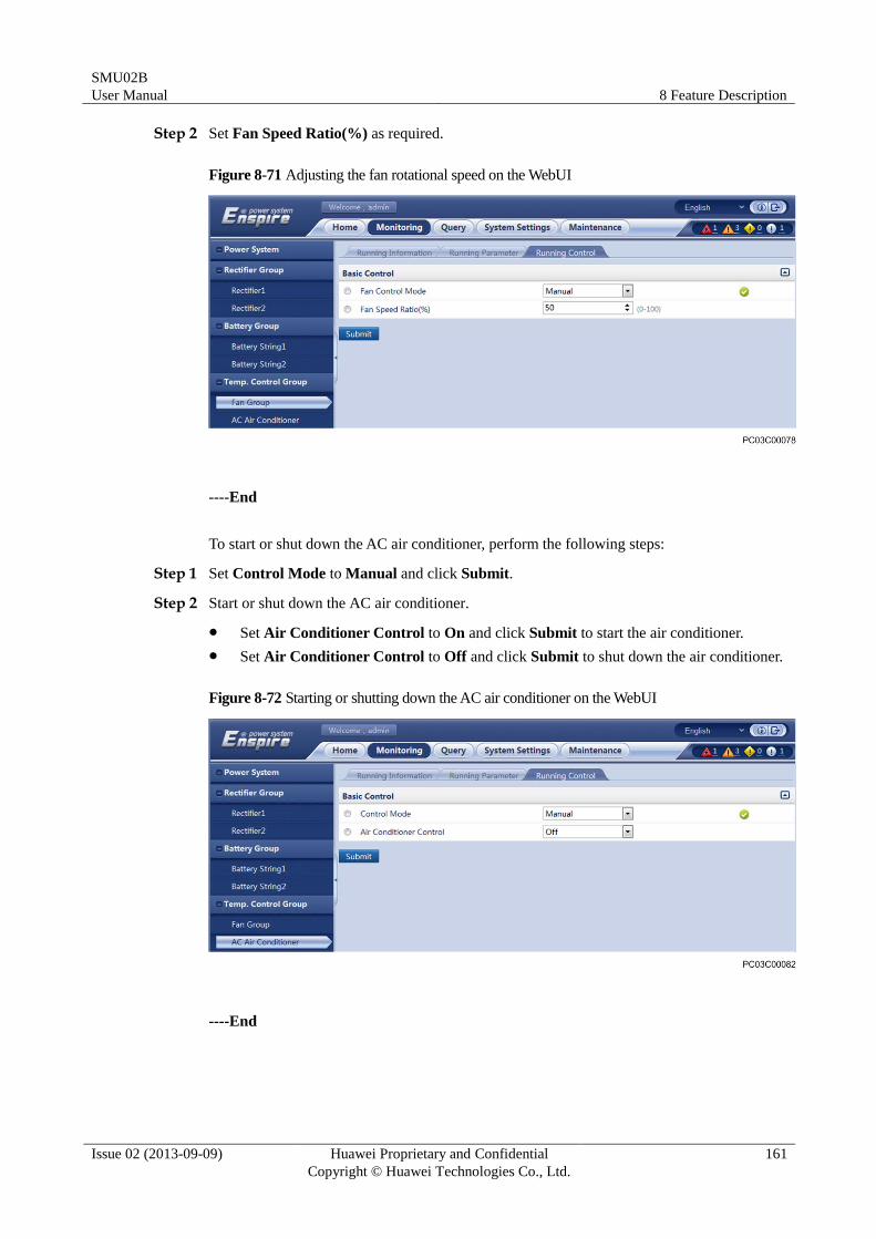
SMU02B
User Manual 8 Feature Description
Issue 02 (2013-09-09) Huawei Proprietary and Confidential
Copyright © Huawei Technologies Co., Ltd.
161
Step 2 Set Fan Speed Ratio(%) as required.
Figure 8-71 Adjusting the fan rotational speed on the WebUI
----End
To start or shut down the AC air conditioner, perform the following steps:
Step 1 Set Control Mode to Manual and click Submit.
Step 2 Start or shut down the AC air conditioner.
Set Air Conditioner Control to On and click Submit to start the air conditioner.
Set Air Conditioner Control to Off and click Submit to shut down the air conditioner.
Figure 8-72 Starting or shutting down the AC air conditioner on the WebUI
----End
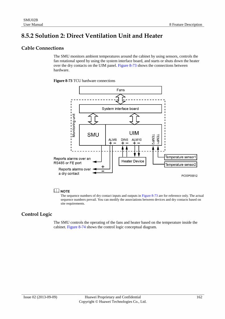
SMU02B
User Manual 8 Feature Description
Issue 02 (2013-09-09) Huawei Proprietary and Confidential
Copyright © Huawei Technologies Co., Ltd.
162
8.5.2 Solution 2: Direct Ventilation Unit and Heater
Cable Connections
The SMU monitors ambient temperatures around the cabinet by using sensors, controls the
fan rotational speed by using the system interface board, and starts or shuts down the heater
over the dry contacts on the UIM panel. Figure 8-73 shows the connections between
hardware.
Figure 8-73 TCU hardware connections
The sequence numbers of dry contact inputs and outputs in Figure 8-73 are for reference only. The actual
sequence numbers prevail. You can modify the associations between devices and dry contacts based on
site requirements.
Control Logic
The SMU controls the operating of the fans and heater based on the temperature inside the
cabinet. Figure 8-74 shows the control logic conceptual diagram.
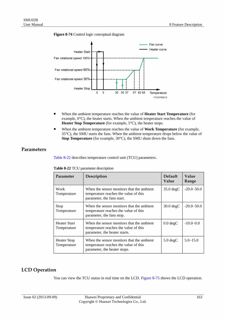
SMU02B
User Manual 8 Feature Description
Issue 02 (2013-09-09) Huawei Proprietary and Confidential
Copyright © Huawei Technologies Co., Ltd.
163
Figure 8-74 Control logic conceptual diagram
When the ambient temperature reaches the value of Heater Start Temperature (for
example, 0°C), the heater starts. When the ambient temperature reaches the value of
Heater Stop Temperature (for example, 5°C), the heater stops.
When the ambient temperature reaches the value of Work Temperature (for example,
35°C), the SMU starts the fans. When the ambient temperature drops below the value of
Stop Temperature (for example, 30°C), the SMU shuts down the fans.
Parameters
Table 8-22 describes temperature control unit (TCU) parameters.
Table 8-22 TCU parameter description
Parameter Description Default Value
Value Range
Work
Temperature
When the sensor monitors that the ambient
temperature reaches the value of this
parameter, the fans start.
35.0 degC -20.0–50.0
Stop
Temperature
When the sensor monitors that the ambient
temperature reaches the value of this
parameter, the fans stop.
30.0 degC -20.0–50.0
Heater Start
Temperature
When the sensor monitors that the ambient
temperature reaches the value of this
parameter, the heater starts.
0.0 degC -10.0–0.0
Heater Stop
Temperature
When the sensor monitors that the ambient
temperature reaches the value of this
parameter, the heater stops.
5.0 degC 5.0–15.0
LCD Operation
You can view the TCU status in real time on the LCD. Figure 8-75 shows the LCD operation.
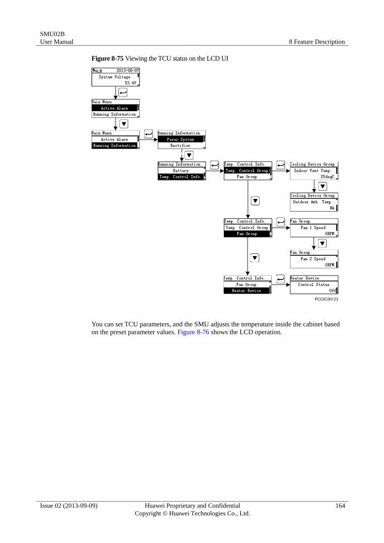
SMU02B
User Manual 8 Feature Description
Issue 02 (2013-09-09) Huawei Proprietary and Confidential
Copyright © Huawei Technologies Co., Ltd.
164
Figure 8-75 Viewing the TCU status on the LCD UI
You can set TCU parameters, and the SMU adjusts the temperature inside the cabinet based
on the preset parameter values. Figure 8-76 shows the LCD operation.
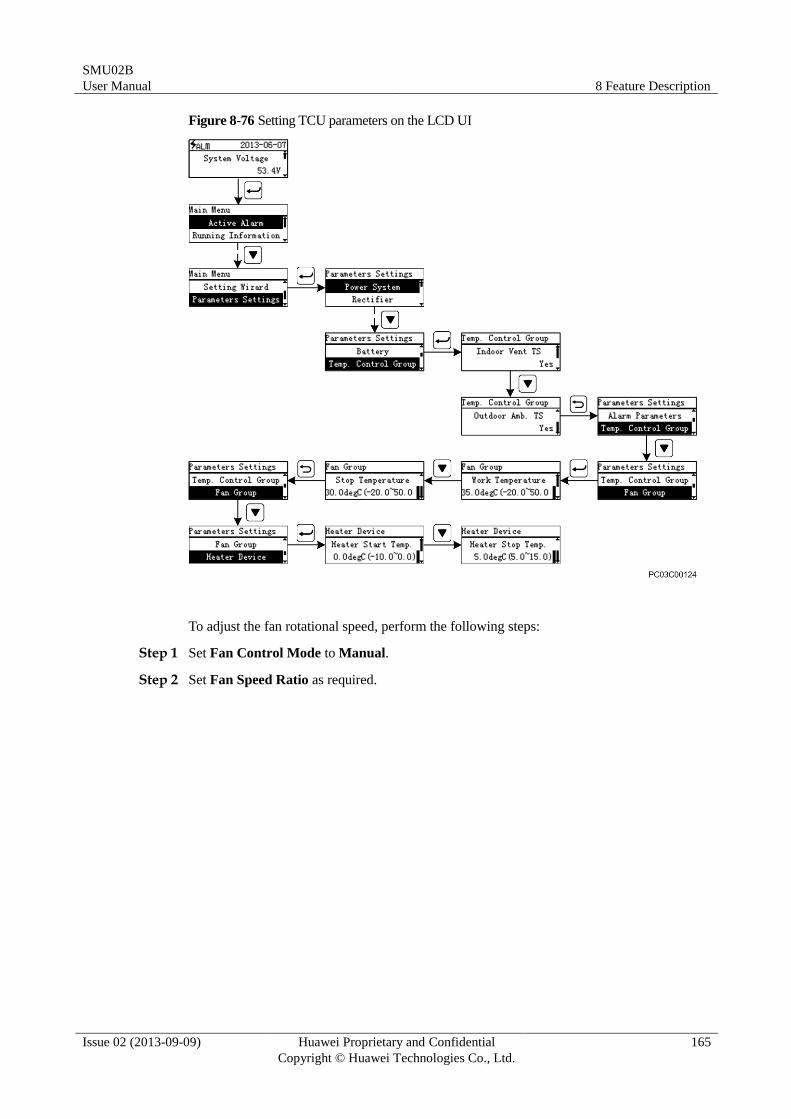
SMU02B
User Manual 8 Feature Description
Issue 02 (2013-09-09) Huawei Proprietary and Confidential
Copyright © Huawei Technologies Co., Ltd.
165
Figure 8-76 Setting TCU parameters on the LCD UI
To adjust the fan rotational speed, perform the following steps:
Step 1 Set Fan Control Mode to Manual.
Step 2 Set Fan Speed Ratio as required.
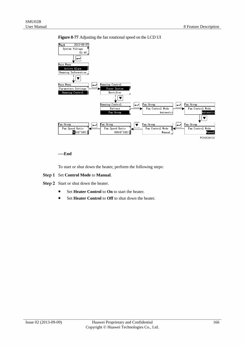
SMU02B
User Manual 8 Feature Description
Issue 02 (2013-09-09) Huawei Proprietary and Confidential
Copyright © Huawei Technologies Co., Ltd.
166
Figure 8-77 Adjusting the fan rotational speed on the LCD UI
----End
To start or shut down the heater, perform the following steps:
Step 1 Set Control Mode to Manual.
Step 2 Start or shut down the heater.
Set Heater Control to On to start the heater.
Set Heater Control to Off to shut down the heater.
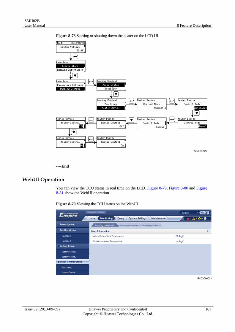
SMU02B
User Manual 8 Feature Description
Issue 02 (2013-09-09) Huawei Proprietary and Confidential
Copyright © Huawei Technologies Co., Ltd.
167
Figure 8-78 Starting or shutting down the heater on the LCD UI
----End
WebUI Operation
You can view the TCU status in real time on the LCD. Figure 8-79, Figure 8-80 and Figure
8-81 show the WebUI operation.
Figure 8-79 Viewing the TCU status on the WebUI
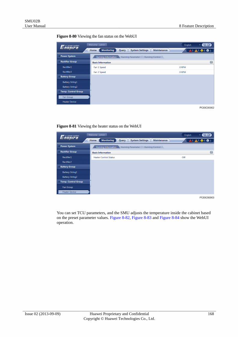
SMU02B
User Manual 8 Feature Description
Issue 02 (2013-09-09) Huawei Proprietary and Confidential
Copyright © Huawei Technologies Co., Ltd.
168
Figure 8-80 Viewing the fan status on the WebUI
Figure 8-81 Viewing the heater status on the WebUI
You can set TCU parameters, and the SMU adjusts the temperature inside the cabinet based
on the preset parameter values. Figure 8-82, Figure 8-83 and Figure 8-84 show the WebUI
operation.
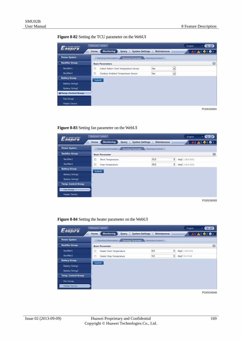
SMU02B
User Manual 8 Feature Description
Issue 02 (2013-09-09) Huawei Proprietary and Confidential
Copyright © Huawei Technologies Co., Ltd.
169
Figure 8-82 Setting the TCU parameter on the WebUI
Figure 8-83 Setting fan parameter on the WebUI
Figure 8-84 Setting the heater parameter on the WebUI
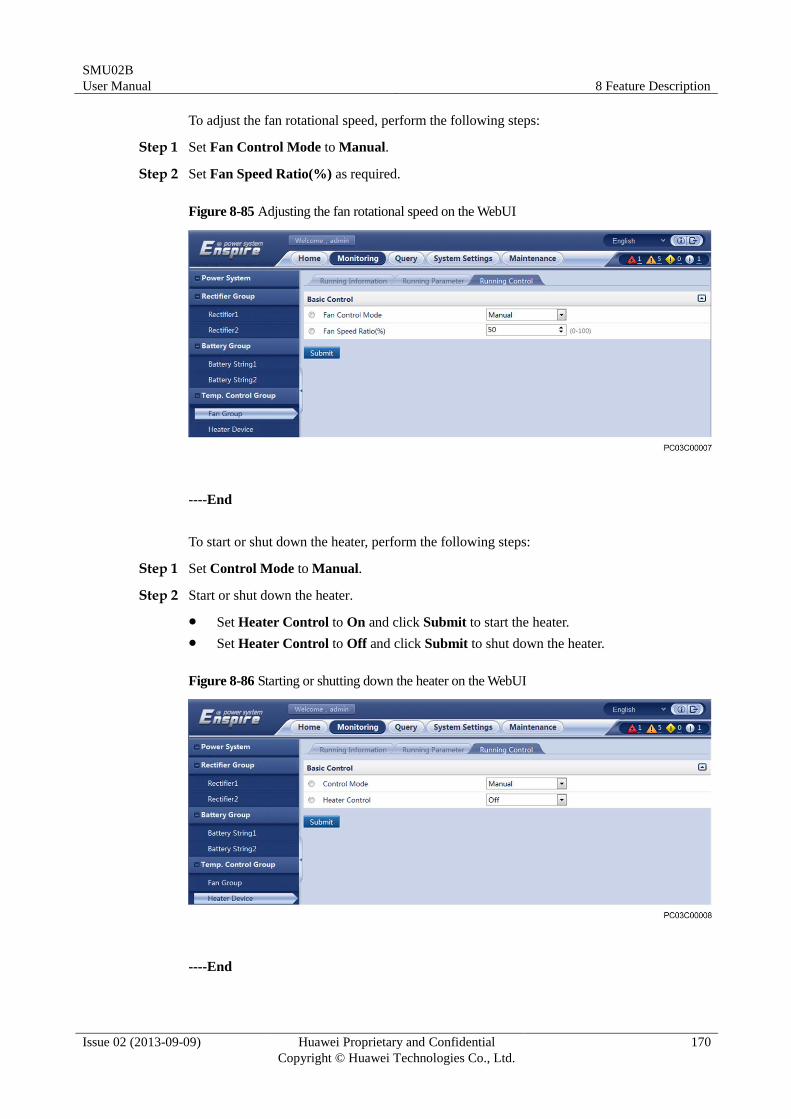
SMU02B
User Manual 8 Feature Description
Issue 02 (2013-09-09) Huawei Proprietary and Confidential
Copyright © Huawei Technologies Co., Ltd.
170
To adjust the fan rotational speed, perform the following steps:
Step 1 Set Fan Control Mode to Manual.
Step 2 Set Fan Speed Ratio(%) as required.
Figure 8-85 Adjusting the fan rotational speed on the WebUI
----End
To start or shut down the heater, perform the following steps:
Step 1 Set Control Mode to Manual.
Step 2 Start or shut down the heater.
Set Heater Control to On and click Submit to start the heater.
Set Heater Control to Off and click Submit to shut down the heater.
Figure 8-86 Starting or shutting down the heater on the WebUI
----End
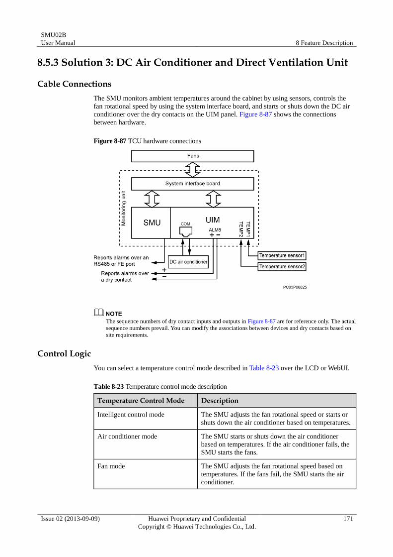
SMU02B
User Manual 8 Feature Description
Issue 02 (2013-09-09) Huawei Proprietary and Confidential
Copyright © Huawei Technologies Co., Ltd.
171
8.5.3 Solution 3: DC Air Conditioner and Direct Ventilation Unit
Cable Connections
The SMU monitors ambient temperatures around the cabinet by using sensors, controls the
fan rotational speed by using the system interface board, and starts or shuts down the DC air
conditioner over the dry contacts on the UIM panel. Figure 8-87 shows the connections
between hardware.
Figure 8-87 TCU hardware connections
The sequence numbers of dry contact inputs and outputs in Figure 8-87 are for reference only. The actual
sequence numbers prevail. You can modify the associations between devices and dry contacts based on
site requirements.
Control Logic
You can select a temperature control mode described in Table 8-23 over the LCD or WebUI.
Table 8-23 Temperature control mode description
Temperature Control Mode Description
Intelligent control mode The SMU adjusts the fan rotational speed or starts or
shuts down the air conditioner based on temperatures.
Air conditioner mode The SMU starts or shuts down the air conditioner
based on temperatures. If the air conditioner fails, the
SMU starts the fans.
Fan mode The SMU adjusts the fan rotational speed based on
temperatures. If the fans fail, the SMU starts the air
conditioner.
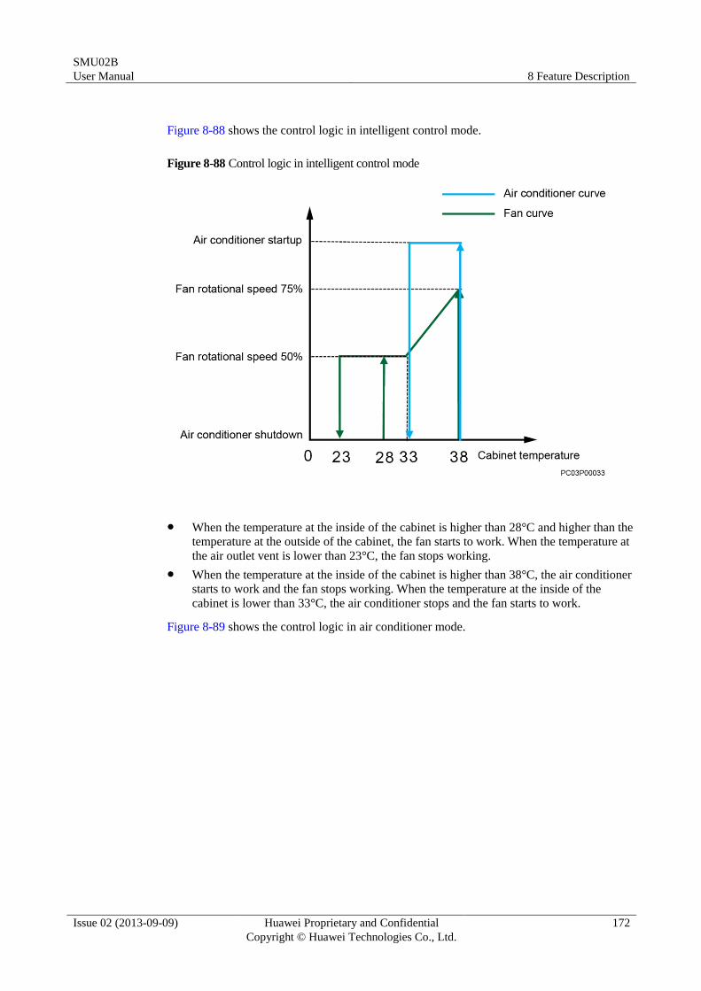
SMU02B
User Manual 8 Feature Description
Issue 02 (2013-09-09) Huawei Proprietary and Confidential
Copyright © Huawei Technologies Co., Ltd.
172
Figure 8-88 shows the control logic in intelligent control mode.
Figure 8-88 Control logic in intelligent control mode
When the temperature at the inside of the cabinet is higher than 28°C and higher than the
temperature at the outside of the cabinet, the fan starts to work. When the temperature at
the air outlet vent is lower than 23°C, the fan stops working.
When the temperature at the inside of the cabinet is higher than 38°C, the air conditioner
starts to work and the fan stops working. When the temperature at the inside of the
cabinet is lower than 33°C, the air conditioner stops and the fan starts to work.
Figure 8-89 shows the control logic in air conditioner mode.
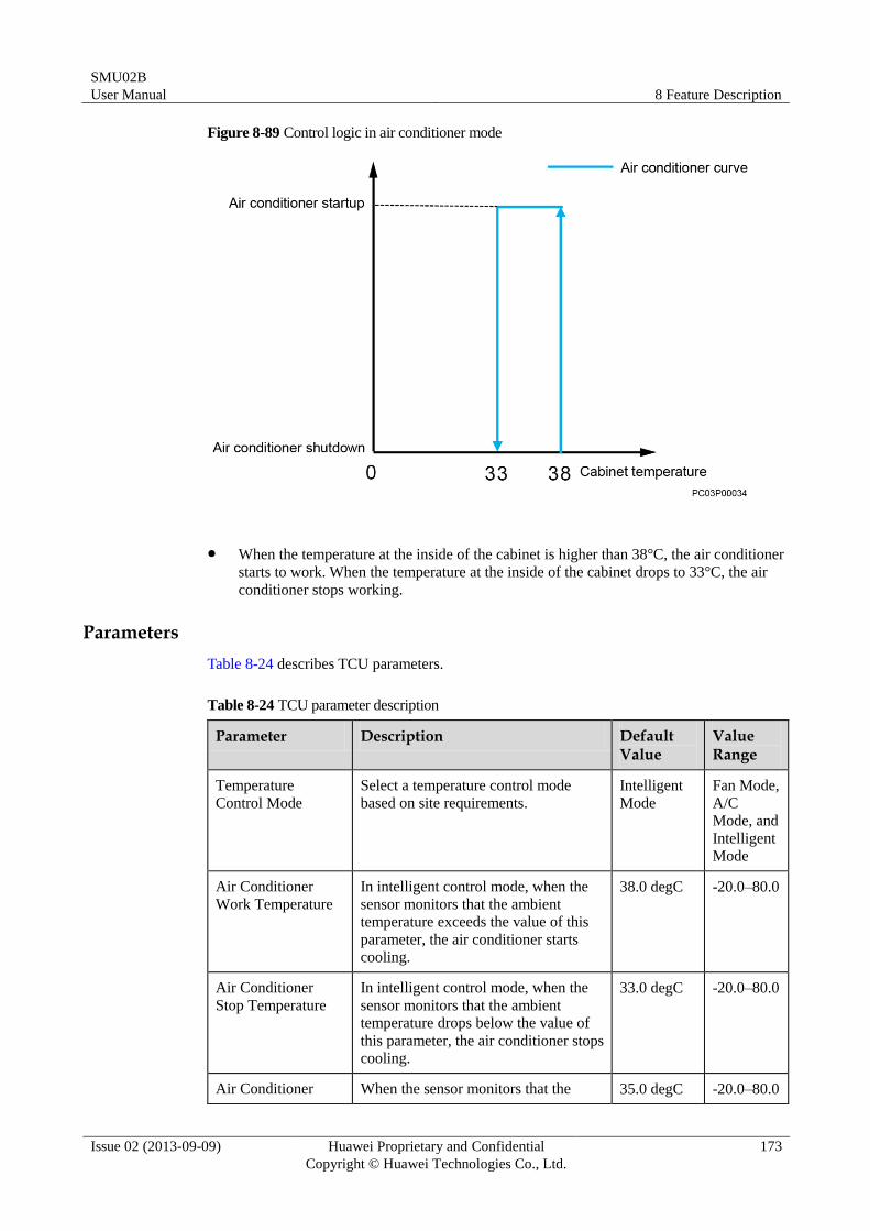
SMU02B
User Manual 8 Feature Description
Issue 02 (2013-09-09) Huawei Proprietary and Confidential
Copyright © Huawei Technologies Co., Ltd.
173
Figure 8-89 Control logic in air conditioner mode
When the temperature at the inside of the cabinet is higher than 38°C, the air conditioner
starts to work. When the temperature at the inside of the cabinet drops to 33°C, the air
conditioner stops working.
Parameters
Table 8-24 describes TCU parameters.
Table 8-24 TCU parameter description
Parameter Description Default Value
Value Range
Temperature
Control Mode
Select a temperature control mode
based on site requirements.
Intelligent
Mode
Fan Mode,
A/C
Mode, and
Intelligent
Mode
Air Conditioner
Work Temperature
In intelligent control mode, when the
sensor monitors that the ambient
temperature exceeds the value of this
parameter, the air conditioner starts
cooling.
38.0 degC -20.0–80.0
Air Conditioner
Stop Temperature
In intelligent control mode, when the
sensor monitors that the ambient
temperature drops below the value of
this parameter, the air conditioner stops
cooling.
33.0 degC -20.0–80.0
Air Conditioner When the sensor monitors that the 35.0 degC -20.0–80.0
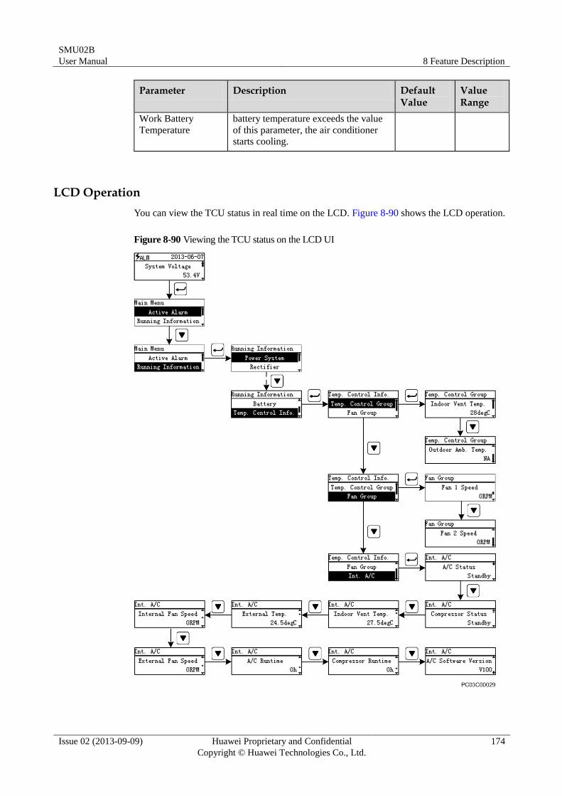
SMU02B
User Manual 8 Feature Description
Issue 02 (2013-09-09) Huawei Proprietary and Confidential
Copyright © Huawei Technologies Co., Ltd.
174
Parameter Description Default Value
Value Range
Work Battery
Temperature
battery temperature exceeds the value
of this parameter, the air conditioner
starts cooling.
LCD Operation
You can view the TCU status in real time on the LCD. Figure 8-90 shows the LCD operation.
Figure 8-90 Viewing the TCU status on the LCD UI
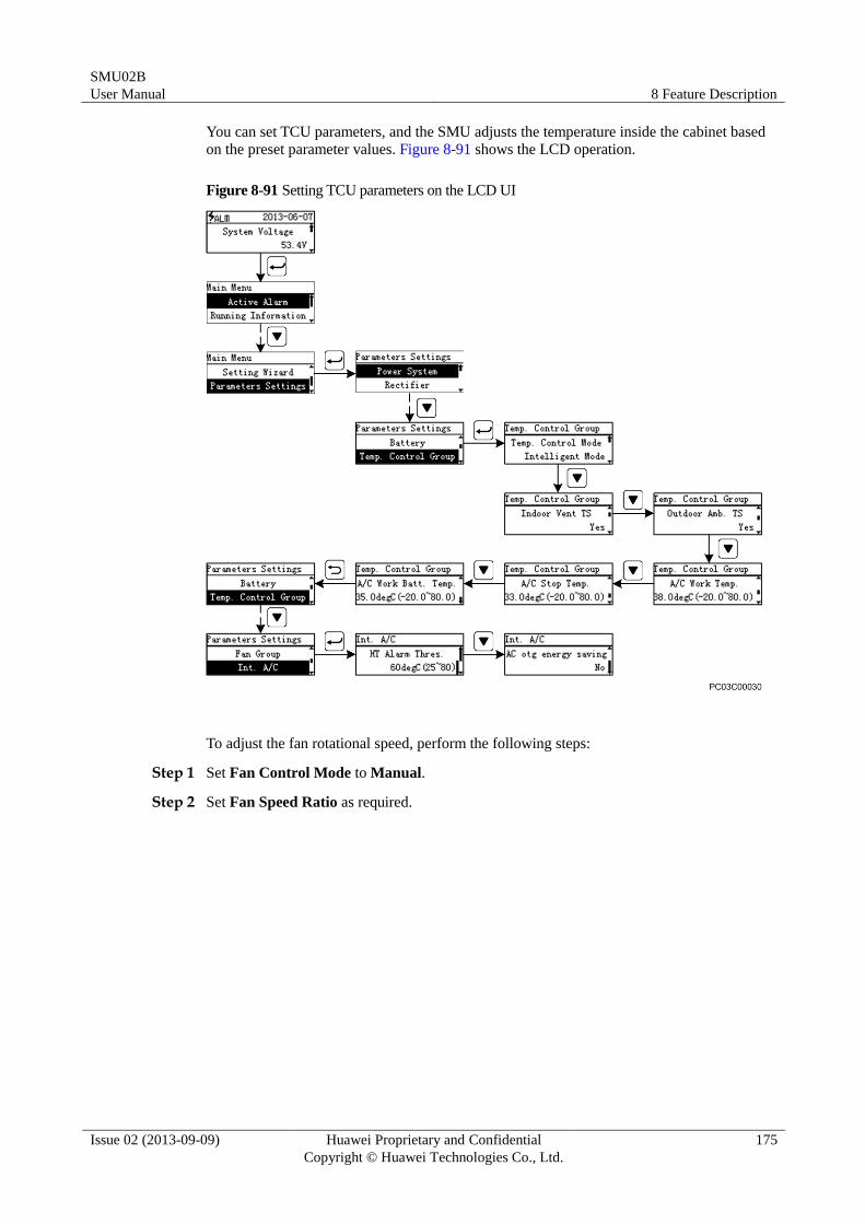
SMU02B
User Manual 8 Feature Description
Issue 02 (2013-09-09) Huawei Proprietary and Confidential
Copyright © Huawei Technologies Co., Ltd.
175
You can set TCU parameters, and the SMU adjusts the temperature inside the cabinet based
on the preset parameter values. Figure 8-91 shows the LCD operation.
Figure 8-91 Setting TCU parameters on the LCD UI
To adjust the fan rotational speed, perform the following steps:
Step 1 Set Fan Control Mode to Manual.
Step 2 Set Fan Speed Ratio as required.
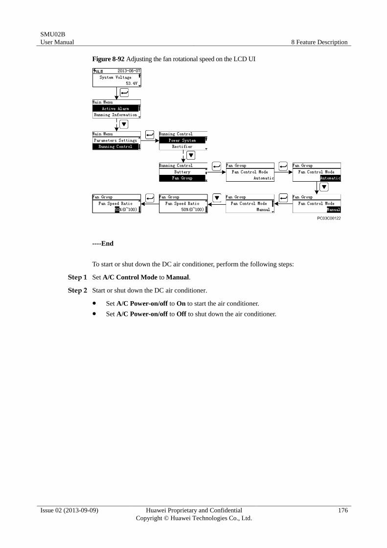
SMU02B
User Manual 8 Feature Description
Issue 02 (2013-09-09) Huawei Proprietary and Confidential
Copyright © Huawei Technologies Co., Ltd.
176
Figure 8-92 Adjusting the fan rotational speed on the LCD UI
----End
To start or shut down the DC air conditioner, perform the following steps:
Step 1 Set A/C Control Mode to Manual.
Step 2 Start or shut down the DC air conditioner.
Set A/C Power-on/off to On to start the air conditioner.
Set A/C Power-on/off to Off to shut down the air conditioner.
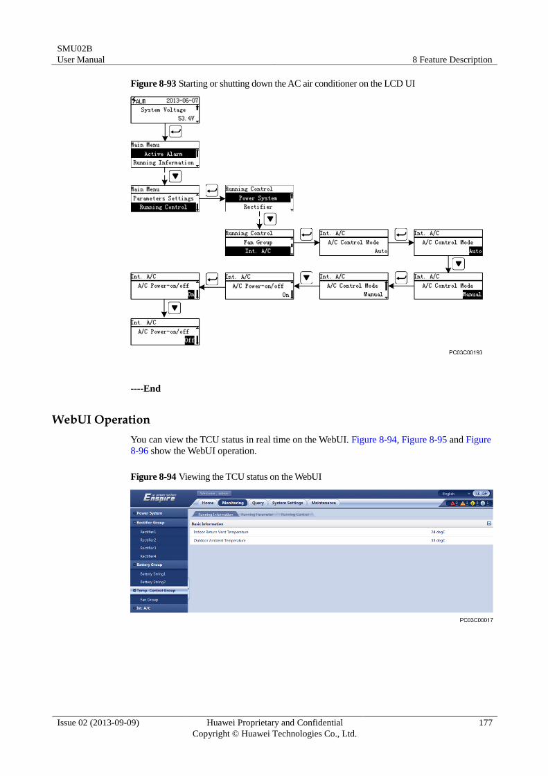
SMU02B
User Manual 8 Feature Description
Issue 02 (2013-09-09) Huawei Proprietary and Confidential
Copyright © Huawei Technologies Co., Ltd.
177
Figure 8-93 Starting or shutting down the AC air conditioner on the LCD UI
----End
WebUI Operation
You can view the TCU status in real time on the WebUI. Figure 8-94, Figure 8-95 and Figure
8-96 show the WebUI operation.
Figure 8-94 Viewing the TCU status on the WebUI
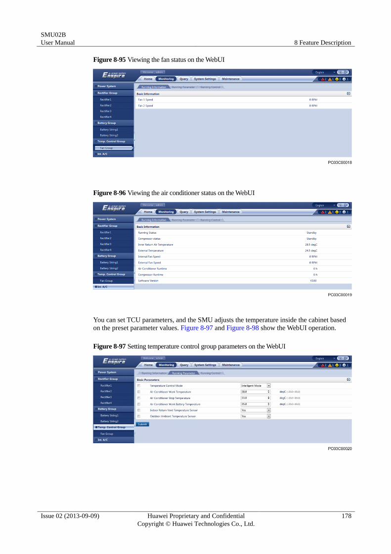
SMU02B
User Manual 8 Feature Description
Issue 02 (2013-09-09) Huawei Proprietary and Confidential
Copyright © Huawei Technologies Co., Ltd.
178
Figure 8-95 Viewing the fan status on the WebUI
Figure 8-96 Viewing the air conditioner status on the WebUI
You can set TCU parameters, and the SMU adjusts the temperature inside the cabinet based
on the preset parameter values. Figure 8-97 and Figure 8-98 show the WebUI operation.
Figure 8-97 Setting temperature control group parameters on the WebUI
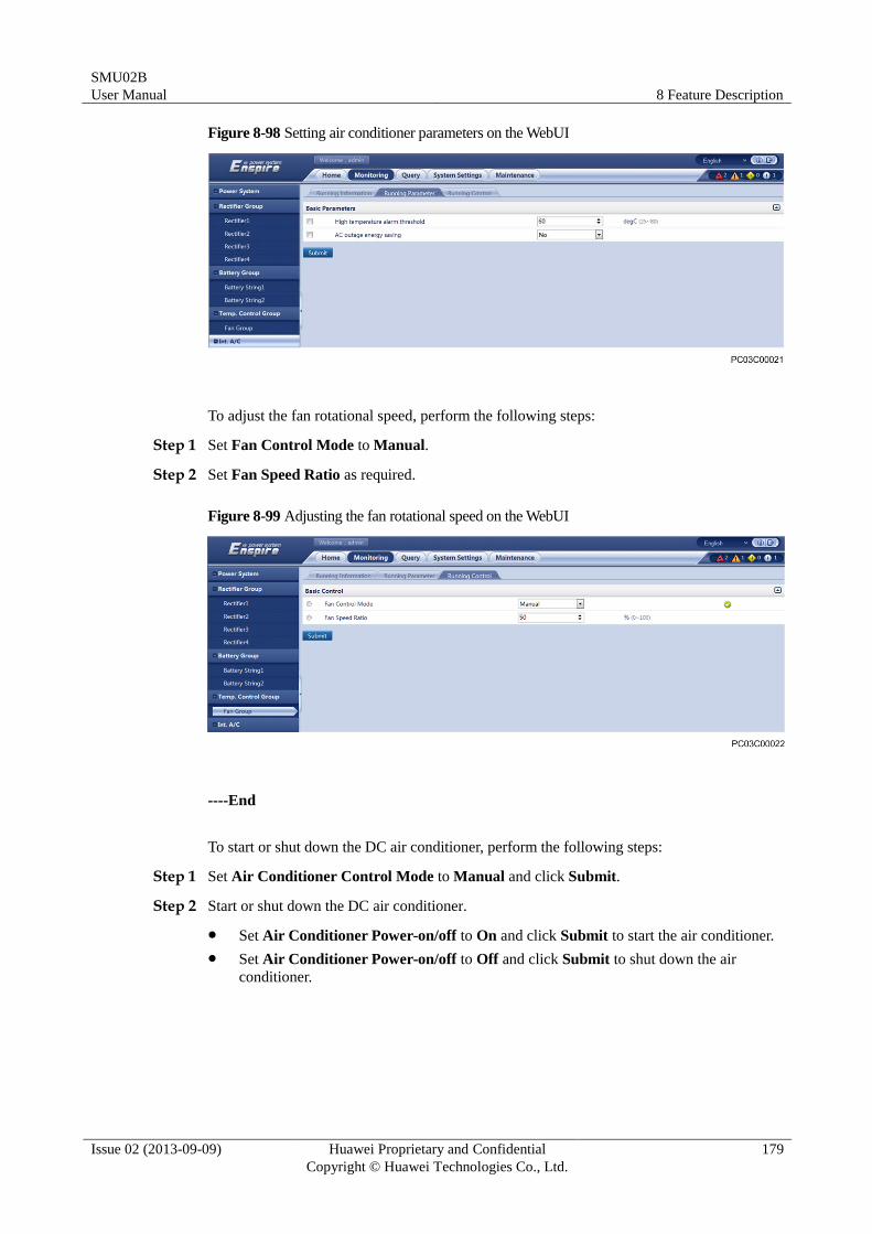
SMU02B
User Manual 8 Feature Description
Issue 02 (2013-09-09) Huawei Proprietary and Confidential
Copyright © Huawei Technologies Co., Ltd.
179
Figure 8-98 Setting air conditioner parameters on the WebUI
To adjust the fan rotational speed, perform the following steps:
Step 1 Set Fan Control Mode to Manual.
Step 2 Set Fan Speed Ratio as required.
Figure 8-99 Adjusting the fan rotational speed on the WebUI
----End
To start or shut down the DC air conditioner, perform the following steps:
Step 1 Set Air Conditioner Control Mode to Manual and click Submit.
Step 2 Start or shut down the DC air conditioner.
Set Air Conditioner Power-on/off to On and click Submit to start the air conditioner.
Set Air Conditioner Power-on/off to Off and click Submit to shut down the air
conditioner.
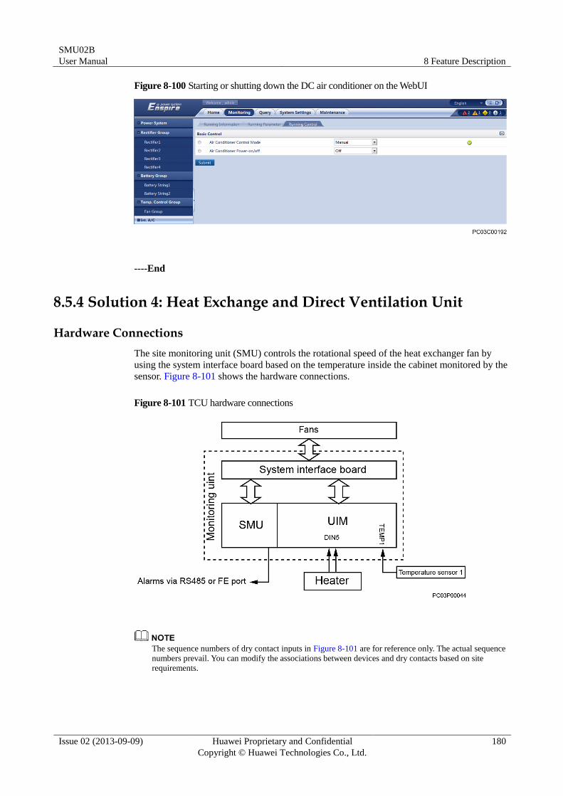
SMU02B
User Manual 8 Feature Description
Issue 02 (2013-09-09) Huawei Proprietary and Confidential
Copyright © Huawei Technologies Co., Ltd.
180
Figure 8-100 Starting or shutting down the DC air conditioner on the WebUI
----End
8.5.4 Solution 4: Heat Exchange and Direct Ventilation Unit
Hardware Connections
The site monitoring unit (SMU) controls the rotational speed of the heat exchanger fan by
using the system interface board based on the temperature inside the cabinet monitored by the
sensor. Figure 8-101 shows the hardware connections.
Figure 8-101 TCU hardware connections
The sequence numbers of dry contact inputs in Figure 8-101 are for reference only. The actual sequence
numbers prevail. You can modify the associations between devices and dry contacts based on site
requirements.
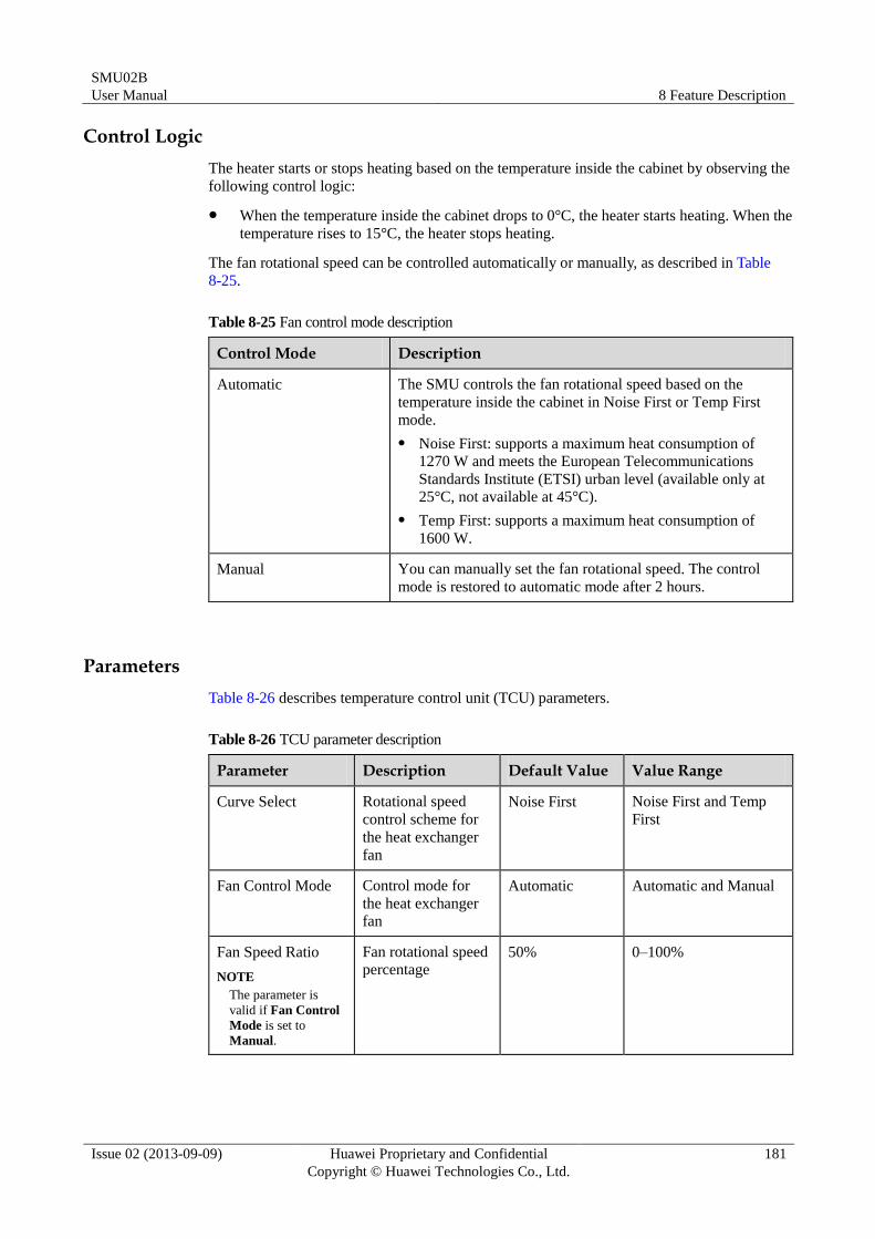
SMU02B
User Manual 8 Feature Description
Issue 02 (2013-09-09) Huawei Proprietary and Confidential
Copyright © Huawei Technologies Co., Ltd.
181
Control Logic
The heater starts or stops heating based on the temperature inside the cabinet by observing the
following control logic:
When the temperature inside the cabinet drops to 0°C, the heater starts heating. When the
temperature rises to 15°C, the heater stops heating.
The fan rotational speed can be controlled automatically or manually, as described in Table
8-25.
Table 8-25 Fan control mode description
Control Mode Description
Automatic The SMU controls the fan rotational speed based on the
temperature inside the cabinet in Noise First or Temp First
mode.
Noise First: supports a maximum heat consumption of
1270 W and meets the European Telecommunications
Standards Institute (ETSI) urban level (available only at
25°C, not available at 45°C).
Temp First: supports a maximum heat consumption of
1600 W.
Manual You can manually set the fan rotational speed. The control
mode is restored to automatic mode after 2 hours.
Parameters
Table 8-26 describes temperature control unit (TCU) parameters.
Table 8-26 TCU parameter description
Parameter Description Default Value Value Range
Curve Select Rotational speed
control scheme for
the heat exchanger
fan
Noise First Noise First and Temp
First
Fan Control Mode Control mode for
the heat exchanger
fan
Automatic Automatic and Manual
Fan Speed Ratio
NOTE
The parameter is
valid if Fan Control
Mode is set to
Manual.
Fan rotational speed
percentage 50% 0–100%
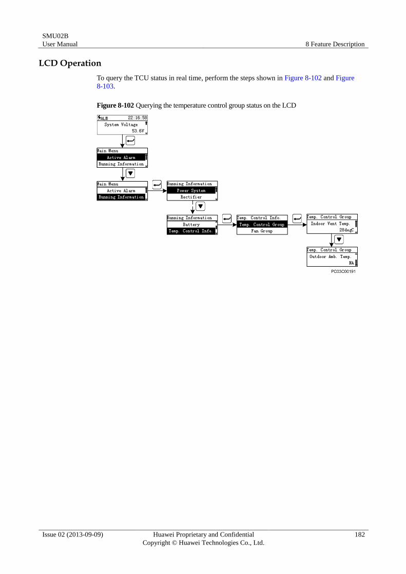
SMU02B
User Manual 8 Feature Description
Issue 02 (2013-09-09) Huawei Proprietary and Confidential
Copyright © Huawei Technologies Co., Ltd.
182
LCD Operation
To query the TCU status in real time, perform the steps shown in Figure 8-102 and Figure
8-103.
Figure 8-102 Querying the temperature control group status on the LCD
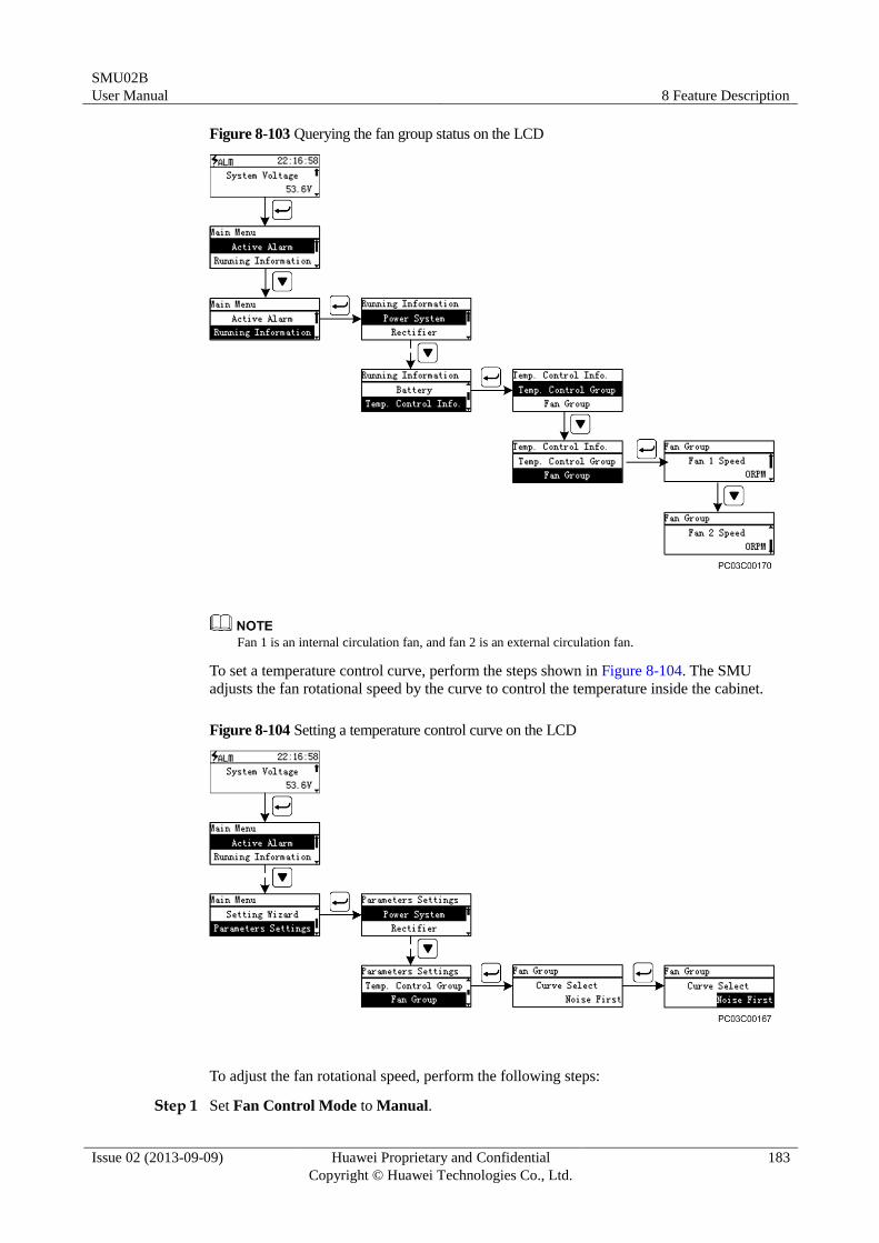
SMU02B
User Manual 8 Feature Description
Issue 02 (2013-09-09) Huawei Proprietary and Confidential
Copyright © Huawei Technologies Co., Ltd.
183
Figure 8-103 Querying the fan group status on the LCD
Fan 1 is an internal circulation fan, and fan 2 is an external circulation fan.
To set a temperature control curve, perform the steps shown in Figure 8-104. The SMU
adjusts the fan rotational speed by the curve to control the temperature inside the cabinet.
Figure 8-104 Setting a temperature control curve on the LCD
To adjust the fan rotational speed, perform the following steps:
Step 1 Set Fan Control Mode to Manual.
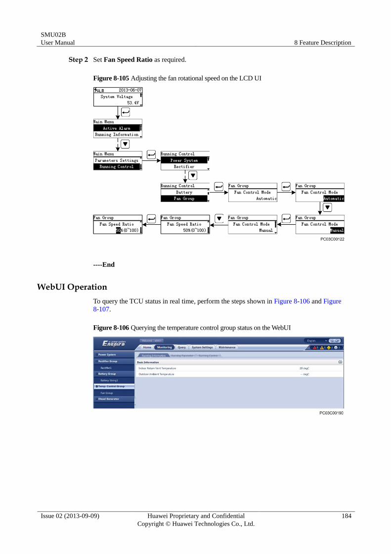
SMU02B
User Manual 8 Feature Description
Issue 02 (2013-09-09) Huawei Proprietary and Confidential
Copyright © Huawei Technologies Co., Ltd.
184
Step 2 Set Fan Speed Ratio as required.
Figure 8-105 Adjusting the fan rotational speed on the LCD UI
----End
WebUI Operation
To query the TCU status in real time, perform the steps shown in Figure 8-106 and Figure
8-107.
Figure 8-106 Querying the temperature control group status on the WebUI
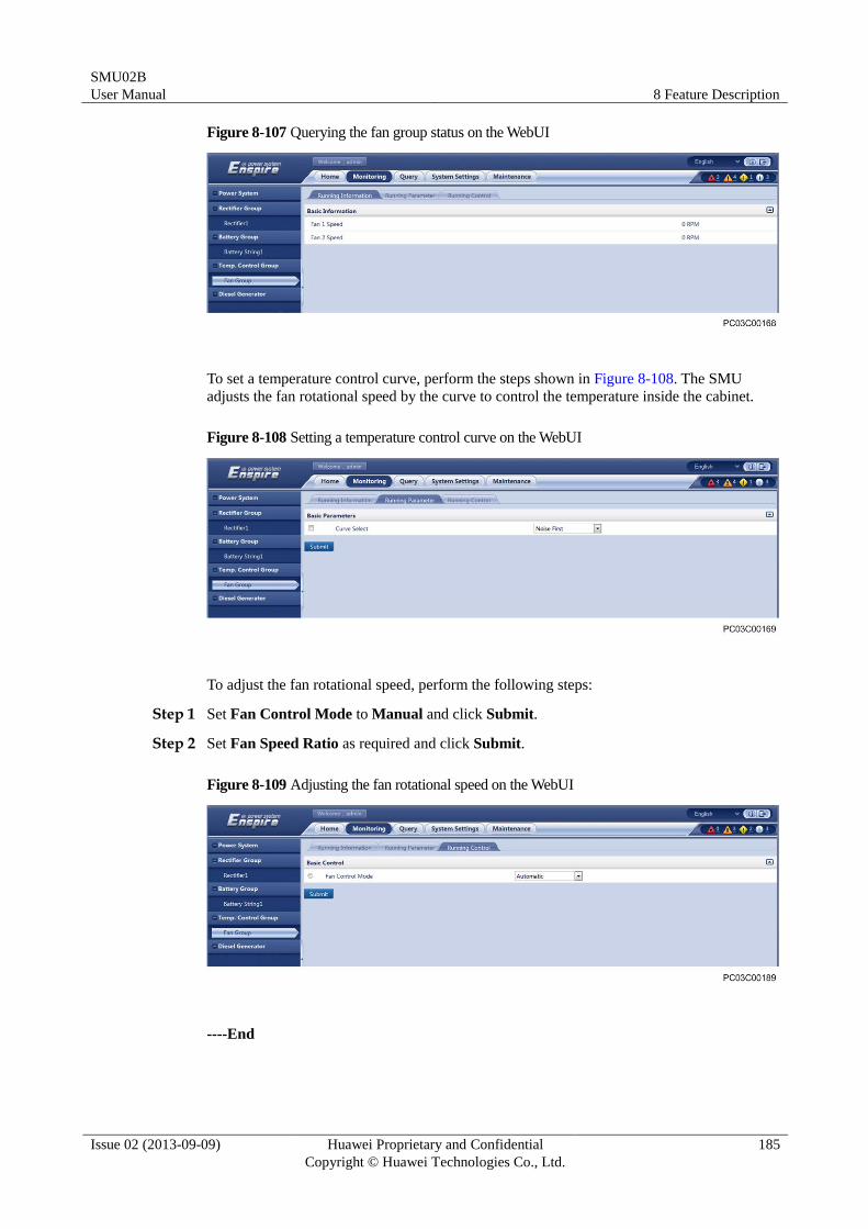
SMU02B
User Manual 8 Feature Description
Issue 02 (2013-09-09) Huawei Proprietary and Confidential
Copyright © Huawei Technologies Co., Ltd.
185
Figure 8-107 Querying the fan group status on the WebUI
To set a temperature control curve, perform the steps shown in Figure 8-108. The SMU
adjusts the fan rotational speed by the curve to control the temperature inside the cabinet.
Figure 8-108 Setting a temperature control curve on the WebUI
To adjust the fan rotational speed, perform the following steps:
Step 1 Set Fan Control Mode to Manual and click Submit.
Step 2 Set Fan Speed Ratio as required and click Submit.
Figure 8-109 Adjusting the fan rotational speed on the WebUI
----End
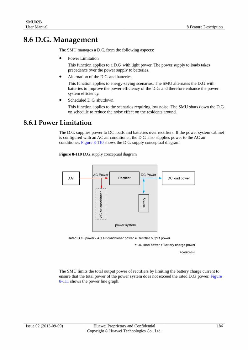
SMU02B
User Manual 8 Feature Description
Issue 02 (2013-09-09) Huawei Proprietary and Confidential
Copyright © Huawei Technologies Co., Ltd.
186
8.6 D.G. Management
The SMU manages a D.G. from the following aspects:
Power Limitation
This function applies to a D.G. with light power. The power supply to loads takes
precedence over the power supply to batteries.
Alternation of the D.G. and batteries
This function applies to energy-saving scenarios. The SMU alternates the D.G. with
batteries to improve the power efficiency of the D.G. and therefore enhance the power
system efficiency.
Scheduled D.G. shutdown
This function applies to the scenarios requiring low noise. The SMU shuts down the D.G.
on schedule to reduce the noise effect on the residents around.
8.6.1 Power Limitation
The D.G. supplies power to DC loads and batteries over rectifiers. If the power system cabinet
is configured with an AC air conditioner, the D.G. also supplies power to the AC air
conditioner. Figure 8-110 shows the D.G. supply conceptual diagram.
Figure 8-110 D.G. supply conceptual diagram
The SMU limits the total output power of rectifiers by limiting the battery charge current to
ensure that the total power of the power system does not exceed the rated D.G. power. Figure
8-111 shows the power line graph.
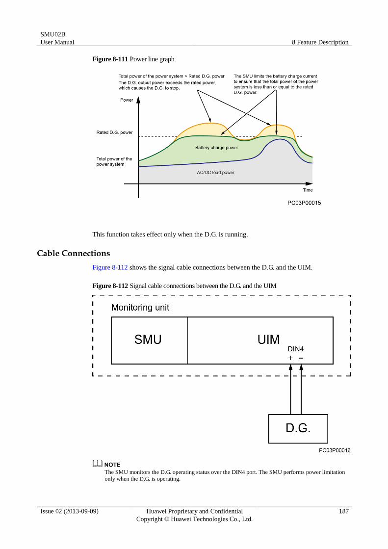
SMU02B
User Manual 8 Feature Description
Issue 02 (2013-09-09) Huawei Proprietary and Confidential
Copyright © Huawei Technologies Co., Ltd.
187
Figure 8-111 Power line graph
This function takes effect only when the D.G. is running.
Cable Connections
Figure 8-112 shows the signal cable connections between the D.G. and the UIM.
Figure 8-112 Signal cable connections between the D.G. and the UIM
The SMU monitors the D.G. operating status over the DIN4 port. The SMU performs power limitation
only when the D.G. is operating.
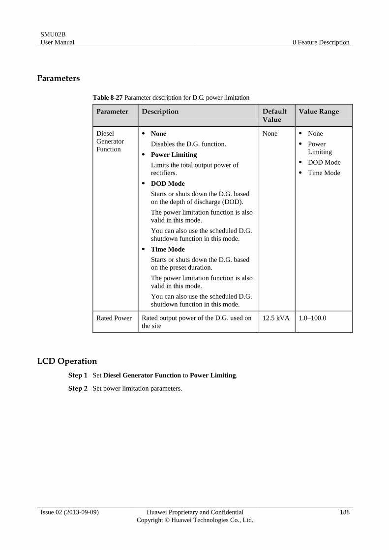
SMU02B
User Manual 8 Feature Description
Issue 02 (2013-09-09) Huawei Proprietary and Confidential
Copyright © Huawei Technologies Co., Ltd.
188
Parameters
Table 8-27 Parameter description for D.G. power limitation
Parameter Description Default Value
Value Range
Diesel
Generator
Function
None
Disables the D.G. function.
Power Limiting
Limits the total output power of
rectifiers.
DOD Mode
Starts or shuts down the D.G. based
on the depth of discharge (DOD).
The power limitation function is also
valid in this mode.
You can also use the scheduled D.G.
shutdown function in this mode.
Time Mode
Starts or shuts down the D.G. based
on the preset duration.
The power limitation function is also
valid in this mode.
You can also use the scheduled D.G.
shutdown function in this mode.
None None
Power
Limiting
DOD Mode
Time Mode
Rated Power Rated output power of the D.G. used on
the site
12.5 kVA 1.0–100.0
LCD Operation
Step 1 Set Diesel Generator Function to Power Limiting.
Step 2 Set power limitation parameters.
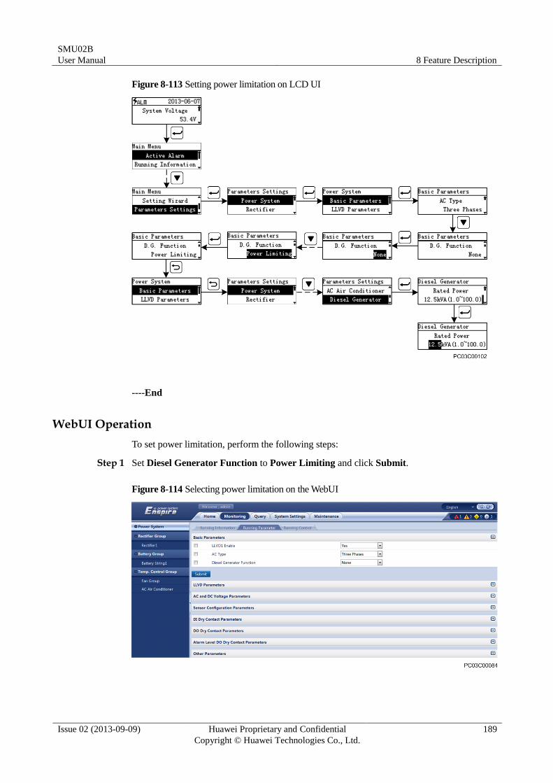
SMU02B
User Manual 8 Feature Description
Issue 02 (2013-09-09) Huawei Proprietary and Confidential
Copyright © Huawei Technologies Co., Ltd.
189
Figure 8-113 Setting power limitation on LCD UI
----End
WebUI Operation
To set power limitation, perform the following steps:
Step 1 Set Diesel Generator Function to Power Limiting and click Submit.
Figure 8-114 Selecting power limitation on the WebUI
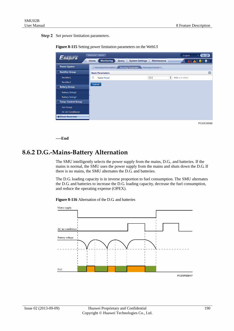
SMU02B
User Manual 8 Feature Description
Issue 02 (2013-09-09) Huawei Proprietary and Confidential
Copyright © Huawei Technologies Co., Ltd.
190
Step 2 Set power limitation parameters.
Figure 8-115 Setting power limitation parameters on the WebUI
----End
8.6.2 D.G.-Mains-Battery Alternation
The SMU intelligently selects the power supply from the mains, D.G., and batteries. If the
mains is normal, the SMU uses the power supply from the mains and shuts down the D.G. If
there is no mains, the SMU alternates the D.G. and batteries.
The D.G. loading capacity is in inverse proportion to fuel consumption. The SMU alternates
the D.G. and batteries to increase the D.G. loading capacity, decrease the fuel consumption,
and reduce the operating expense (OPEX).
Figure 8-116 Alternation of the D.G. and batteries
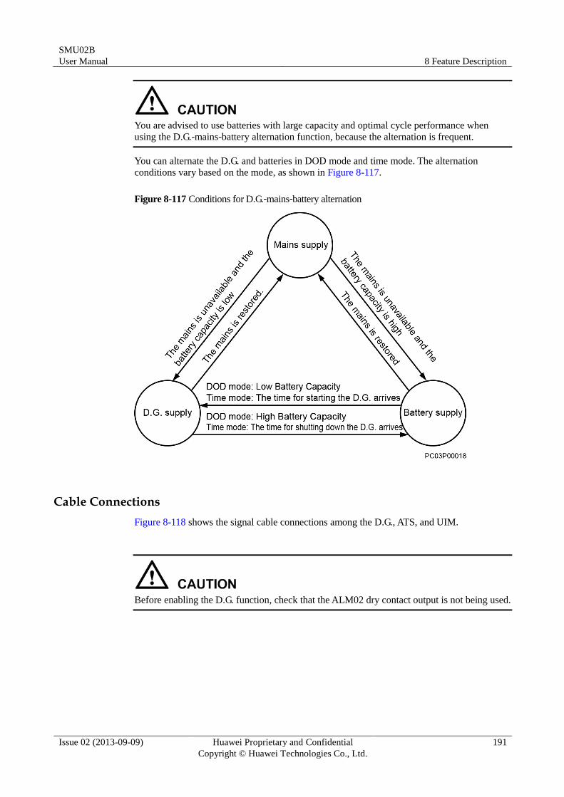
SMU02B
User Manual 8 Feature Description
Issue 02 (2013-09-09) Huawei Proprietary and Confidential
Copyright © Huawei Technologies Co., Ltd.
191
You are advised to use batteries with large capacity and optimal cycle performance when
using the D.G.-mains-battery alternation function, because the alternation is frequent.
You can alternate the D.G. and batteries in DOD mode and time mode. The alternation
conditions vary based on the mode, as shown in Figure 8-117.
Figure 8-117 Conditions for D.G.-mains-battery alternation
Cable Connections
Figure 8-118 shows the signal cable connections among the D.G., ATS, and UIM.
Before enabling the D.G. function, check that the ALM02 dry contact output is not being used.
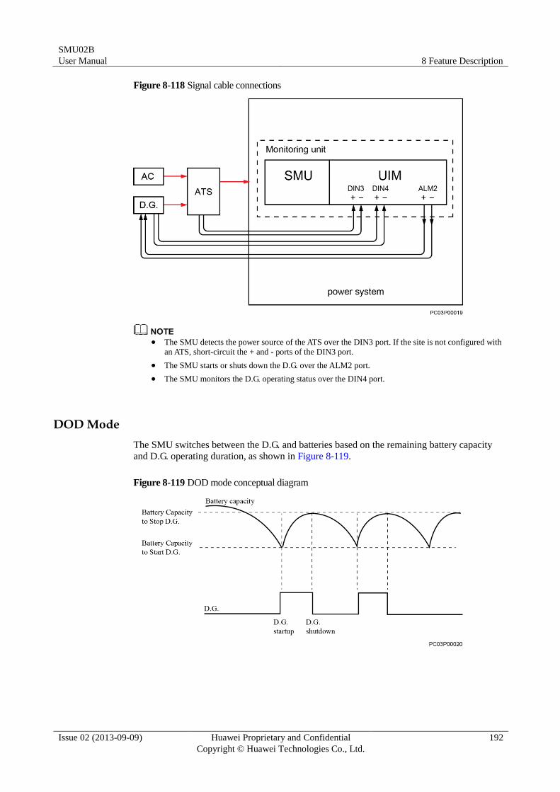
SMU02B
User Manual 8 Feature Description
Issue 02 (2013-09-09) Huawei Proprietary and Confidential
Copyright © Huawei Technologies Co., Ltd.
192
Figure 8-118 Signal cable connections
The SMU detects the power source of the ATS over the DIN3 port. If the site is not configured with
an ATS, short-circuit the + and - ports of the DIN3 port.
The SMU starts or shuts down the D.G. over the ALM2 port.
The SMU monitors the D.G. operating status over the DIN4 port.
DOD Mode
The SMU switches between the D.G. and batteries based on the remaining battery capacity
and D.G. operating duration, as shown in Figure 8-119.
Figure 8-119 DOD mode conceptual diagram
SMU02B
User Manual 8 Feature Description
Issue 02 (2013-09-09) Huawei Proprietary and Confidential
Copyright © Huawei Technologies Co., Ltd.
193
Parameters
Table 8-28 DOD mode parameter description
Parameter Description Default Value
Value Range
Diesel Generator
Function
None
Disables the D.G. function.
Power Limiting
Limits the total output power of
rectifiers.
DOD Mode
Starts or shuts down the D.G. based
on the depth of discharge (DOD).
The power limitation function is also
valid in this mode.
You can also use the scheduled D.G.
shutdown function in this mode.
Time Mode
Starts or shuts down the D.G. based
on the preset duration.
The power limitation function is also
valid in this mode.
You can also use the scheduled D.G.
shutdown function in this mode.
None None
Power
Limiting
DOD
Mode
Time
Mode
Rated Power Rated output power of the D.G. used on
the site
12.5 kVA 1.0–100.0
Battery Capacity
to Start D.G.
A remaining battery capacity percentage
below which the SMU starts the D.G.
30% 20–90
Battery Capacity
to Stop D.G.
A remaining battery capacity percentage
above which the SMU shuts down the
D.G.
90% 10–100
Minimum
Runtime
The shortest duration within which the
D.G. operates continuously
To ensure sufficient power supply to
batteries, the continuous D.G. operating
duration must be greater than or equal to
the value of this parameter.
1 h 0–5
Maximum
Runtime
The longest duration within which the
D.G. operates continuously
After the continuous D.G. operating
duration reaches the value of this
parameter, the D.G. shuts down and
batteries start to supply power.
12 h 6–100
SMU02B
User Manual 8 Feature Description
Issue 02 (2013-09-09) Huawei Proprietary and Confidential
Copyright © Huawei Technologies Co., Ltd.
194
LCD Operation
Step 1 Set D.G. Function to DOD Mode.
Step 2 Set DOD mode parameters.
Figure 8-120 Setting the DOD mode on LCD UI
----End
WebUI Operation
To set the DOD mode, perform the following steps:
Step 1 Set Diesel Generator Function to DOD Mode and click Submit.
SMU02B
User Manual 8 Feature Description
Issue 02 (2013-09-09) Huawei Proprietary and Confidential
Copyright © Huawei Technologies Co., Ltd.
195
Figure 8-121 Selecting the DOD mode on WebUI
Step 2 Set DOD mode parameters.
Figure 8-122 Setting DOD mode parameters on the WebUI
----End
Time Mode
The SMU switches between the D.G. and batteries based on the preset D.G. operating duration
and stop duration. Figure 8-123 shows the time mode conceptual diagram.
SMU02B
User Manual 8 Feature Description
Issue 02 (2013-09-09) Huawei Proprietary and Confidential
Copyright © Huawei Technologies Co., Ltd.
196
Figure 8-123 Time mode conceptual diagram
Parameters
Table 8-29 Time mode parameter description
Parameter Description Default Value
Value Range
Diesel Generator
Function
None
Disables the D.G. function.
Power Limiting
Limits the total output power of
rectifiers.
DOD Mode
Starts or shuts down the D.G. based on
the depth of discharge (DOD).
The power limitation function is also
valid in this mode.
You can also use the scheduled D.G.
shutdown function in this mode.
Time Mode
Starts or shuts down the D.G. based on
the preset duration.
The power limitation function is also
valid in this mode.
You can also use the scheduled D.G.
shutdown function in this mode.
None None
Power
Limiting
DOD
Mode
Time
Mode
Rated Power Rated output power of the D.G. used on
the site
12.5 kVA 1.0–100.0
Running
Duration
After the continuous D.G. operating
duration reaches the value of this
parameter, the D.G. shuts down and
5 h 1–100
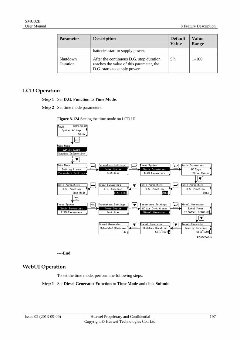
SMU02B
User Manual 8 Feature Description
Issue 02 (2013-09-09) Huawei Proprietary and Confidential
Copyright © Huawei Technologies Co., Ltd.
197
Parameter Description Default Value
Value Range
batteries start to supply power.
Shutdown
Duration
After the continuous D.G. stop duration
reaches the value of this parameter, the
D.G. starts to supply power.
5 h 1–100
LCD Operation
Step 1 Set D.G. Function to Time Mode.
Step 2 Set time mode parameters.
Figure 8-124 Setting the time mode on LCD UI
----End
WebUI Operation
To set the time mode, perform the following steps:
Step 1 Set Diesel Generator Function to Time Mode and click Submit.
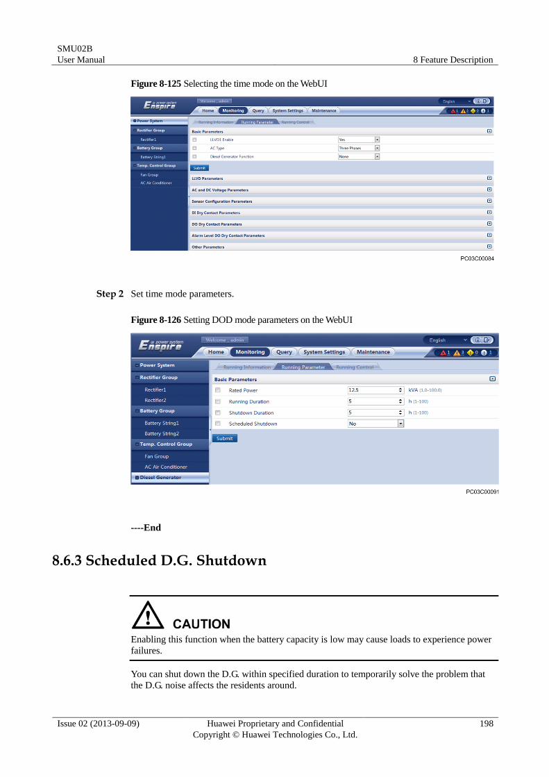
SMU02B
User Manual 8 Feature Description
Issue 02 (2013-09-09) Huawei Proprietary and Confidential
Copyright © Huawei Technologies Co., Ltd.
198
Figure 8-125 Selecting the time mode on the WebUI
Step 2 Set time mode parameters.
Figure 8-126 Setting DOD mode parameters on the WebUI
----End
8.6.3 Scheduled D.G. Shutdown
Enabling this function when the battery capacity is low may cause loads to experience power
failures.
You can shut down the D.G. within specified duration to temporarily solve the problem that
the D.G. noise affects the residents around.
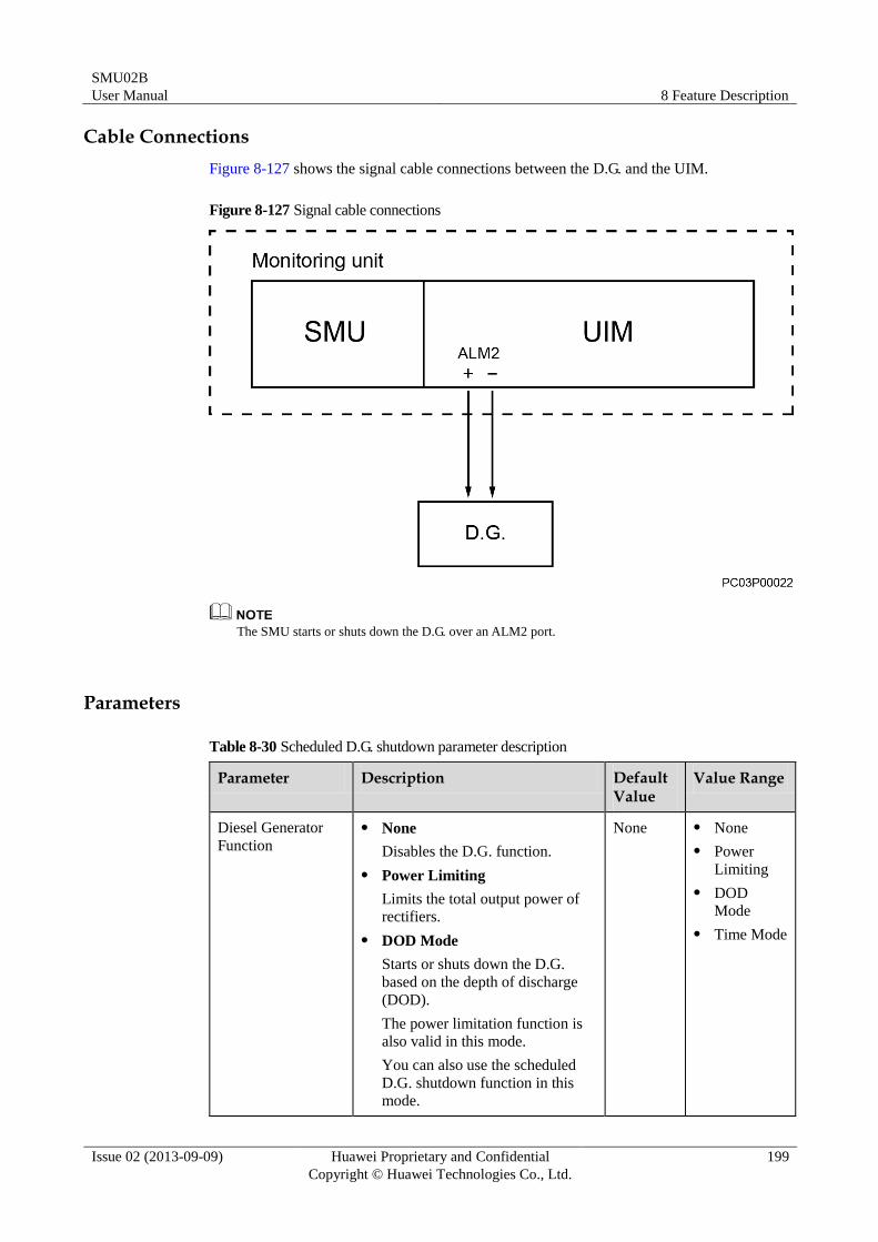
SMU02B
User Manual 8 Feature Description
Issue 02 (2013-09-09) Huawei Proprietary and Confidential
Copyright © Huawei Technologies Co., Ltd.
199
Cable Connections
Figure 8-127 shows the signal cable connections between the D.G. and the UIM.
Figure 8-127 Signal cable connections
The SMU starts or shuts down the D.G. over an ALM2 port.
Parameters
Table 8-30 Scheduled D.G. shutdown parameter description
Parameter Description Default Value
Value Range
Diesel Generator
Function
None
Disables the D.G. function.
Power Limiting
Limits the total output power of
rectifiers.
DOD Mode
Starts or shuts down the D.G.
based on the depth of discharge
(DOD).
The power limitation function is
also valid in this mode.
You can also use the scheduled
D.G. shutdown function in this mode.
None None
Power
Limiting
DOD
Mode
Time Mode
SMU02B
User Manual 8 Feature Description
Issue 02 (2013-09-09) Huawei Proprietary and Confidential
Copyright © Huawei Technologies Co., Ltd.
200
Parameter Description Default Value
Value Range
Time Mode
Starts or shuts down the D.G.
based on the preset duration.
The power limitation function is
also valid in this mode.
You can also use the scheduled
D.G. shutdown function in this
mode.
Scheduled
Shutdown
NOTE
This parameter is
displayed and valid
only when Diesel
Generator Function is set to DOD Mode
or Time Mode.
Indicates whether to allow the D.G.
to be shut down within a specific
duration.
No Yes
No
Scheduled
Shutdown Start
Time
NOTE
This parameter is
displayed and valid
only when
Scheduled
Shutdown is set to
Yes.
Start time of the D.G. shutdown
duration
21:00:00 Any time
Scheduled
Shutdown End
Time
End time of the D.G. shutdown
duration
05:00:00 Any time
LCD Operation
To shut down the D.G. on schedule, perform the following steps:
Step 1 Set Diesel Generator Function to Time Mode.
Step 2 Set Scheduled Shutdown to Yes.
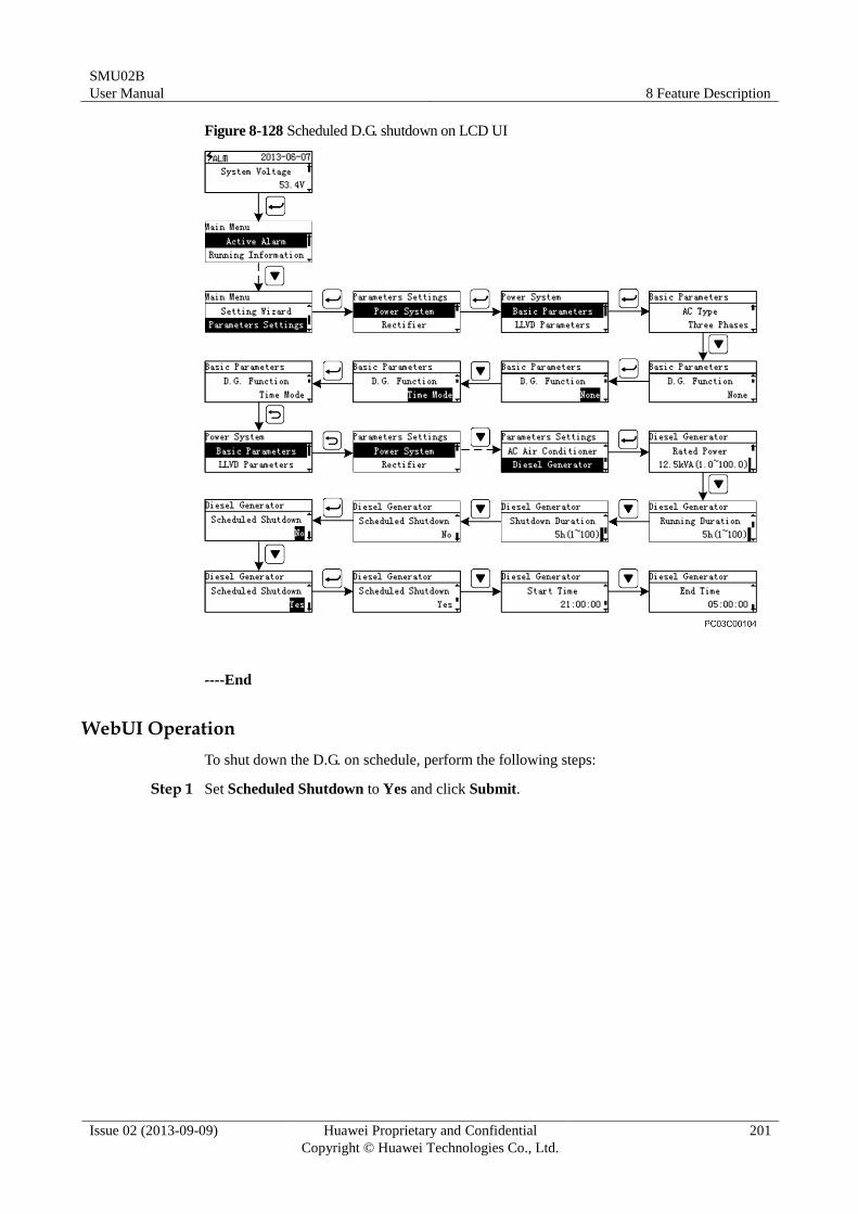
SMU02B
User Manual 8 Feature Description
Issue 02 (2013-09-09) Huawei Proprietary and Confidential
Copyright © Huawei Technologies Co., Ltd.
201
Figure 8-128 Scheduled D.G. shutdown on LCD UI
----End
WebUI Operation
To shut down the D.G. on schedule, perform the following steps:
Step 1 Set Scheduled Shutdown to Yes and click Submit.
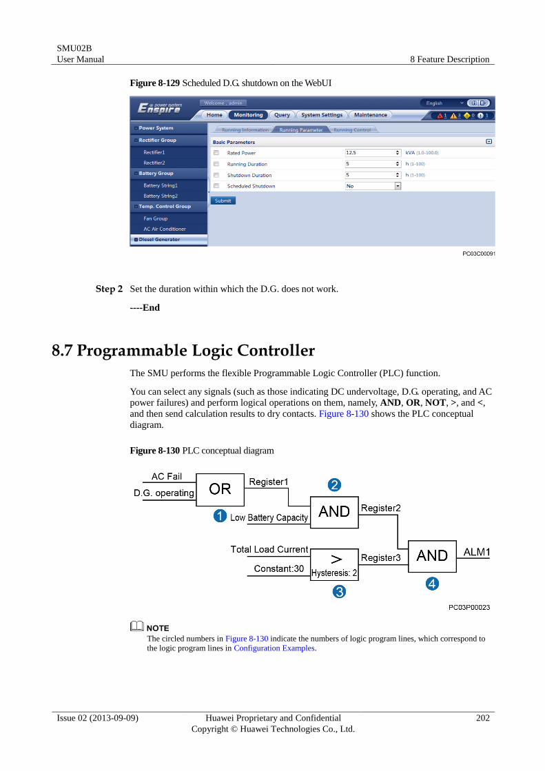
SMU02B
User Manual 8 Feature Description
Issue 02 (2013-09-09) Huawei Proprietary and Confidential
Copyright © Huawei Technologies Co., Ltd.
202
Figure 8-129 Scheduled D.G. shutdown on the WebUI
Step 2 Set the duration within which the D.G. does not work.
----End
8.7 Programmable Logic Controller
The SMU performs the flexible Programmable Logic Controller (PLC) function.
You can select any signals (such as those indicating DC undervoltage, D.G. operating, and AC
power failures) and perform logical operations on them, namely, AND, OR, NOT, >, and <,
and then send calculation results to dry contacts. Figure 8-130 shows the PLC conceptual
diagram.
Figure 8-130 PLC conceptual diagram
The circled numbers in Figure 8-130 indicate the numbers of logic program lines, which correspond to
the logic program lines in Configuration Examples.
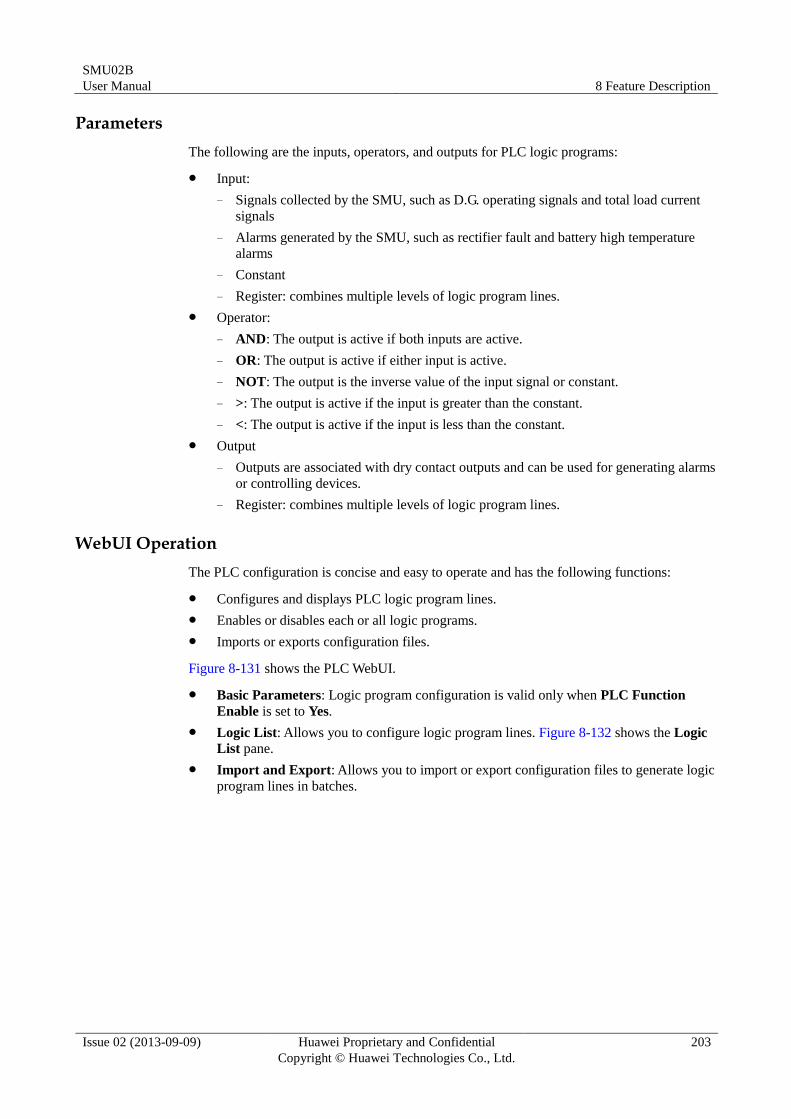
SMU02B
User Manual 8 Feature Description
Issue 02 (2013-09-09) Huawei Proprietary and Confidential
Copyright © Huawei Technologies Co., Ltd.
203
Parameters
The following are the inputs, operators, and outputs for PLC logic programs:
Input:
− Signals collected by the SMU, such as D.G. operating signals and total load current
signals
− Alarms generated by the SMU, such as rectifier fault and battery high temperature
alarms
− Constant
− Register: combines multiple levels of logic program lines.
Operator:
− AND: The output is active if both inputs are active.
− OR: The output is active if either input is active.
− NOT: The output is the inverse value of the input signal or constant.
− >: The output is active if the input is greater than the constant.
− <: The output is active if the input is less than the constant.
Output
− Outputs are associated with dry contact outputs and can be used for generating alarms
or controlling devices.
− Register: combines multiple levels of logic program lines.
WebUI Operation
The PLC configuration is concise and easy to operate and has the following functions:
Configures and displays PLC logic program lines.
Enables or disables each or all logic programs.
Imports or exports configuration files.
Figure 8-131 shows the PLC WebUI.
Basic Parameters: Logic program configuration is valid only when PLC Function
Enable is set to Yes.
Logic List: Allows you to configure logic program lines. Figure 8-132 shows the Logic
List pane.
Import and Export: Allows you to import or export configuration files to generate logic
program lines in batches.
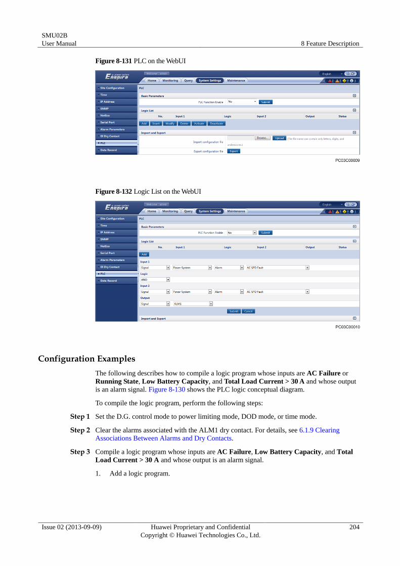
SMU02B
User Manual 8 Feature Description
Issue 02 (2013-09-09) Huawei Proprietary and Confidential
Copyright © Huawei Technologies Co., Ltd.
204
Figure 8-131 PLC on the WebUI
Figure 8-132 Logic List on the WebUI
Configuration Examples
The following describes how to compile a logic program whose inputs are AC Failure or
Running State, Low Battery Capacity, and Total Load Current > 30 A and whose output
is an alarm signal. Figure 8-130 shows the PLC logic conceptual diagram.
To compile the logic program, perform the following steps:
Step 1 Set the D.G. control mode to power limiting mode, DOD mode, or time mode.
Step 2 Clear the alarms associated with the ALM1 dry contact. For details, see 6.1.9 Clearing
Associations Between Alarms and Dry Contacts.
Step 3 Compile a logic program whose inputs are AC Failure, Low Battery Capacity, and Total
Load Current > 30 A and whose output is an alarm signal.
1. Add a logic program.
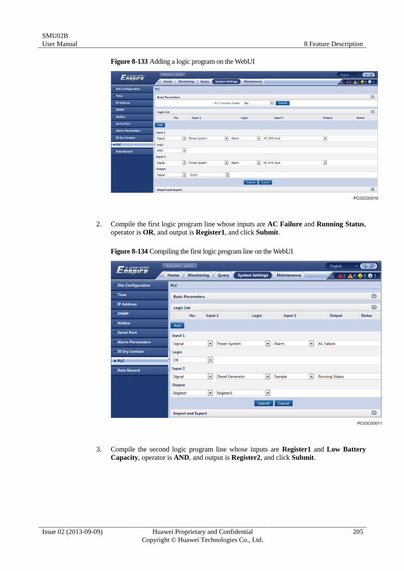
SMU02B
User Manual 8 Feature Description
Issue 02 (2013-09-09) Huawei Proprietary and Confidential
Copyright © Huawei Technologies Co., Ltd.
205
Figure 8-133 Adding a logic program on the WebUI
2. Compile the first logic program line whose inputs are AC Failure and Running Status,
operator is OR, and output is Register1, and click Submit.
Figure 8-134 Compiling the first logic program line on the WebUI
3. Compile the second logic program line whose inputs are Register1 and Low Battery
Capacity, operator is AND, and output is Register2, and click Submit.
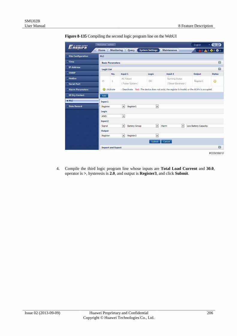
SMU02B
User Manual 8 Feature Description
Issue 02 (2013-09-09) Huawei Proprietary and Confidential
Copyright © Huawei Technologies Co., Ltd.
206
Figure 8-135 Compiling the second logic program line on the WebUI
4. Compile the third logic program line whose inputs are Total Load Current and 30.0,
operator is >, hysteresis is 2.0, and output is Register3, and click Submit.
SMU02B
User Manual 8 Feature Description
Issue 02 (2013-09-09) Huawei Proprietary and Confidential
Copyright © Huawei Technologies Co., Ltd.
207
Figure 8-136 Compiling the third logic program line on the WebUI
5. Compile the fourth logic program line whose inputs are Register2 and Register3,
operator is AND, and output is ALM1, and click Submit.
SMU02B
User Manual 8 Feature Description
Issue 02 (2013-09-09) Huawei Proprietary and Confidential
Copyright © Huawei Technologies Co., Ltd.
208
Figure 8-137 Compiling the fourth logic program line on the WebUI
Step 4 Activate the program lines one by one that you submit on the logic list. After a program line is
activated, a green icon is displayed in the Status column.
Figure 8-138 Logic program lines activated on the WebUI
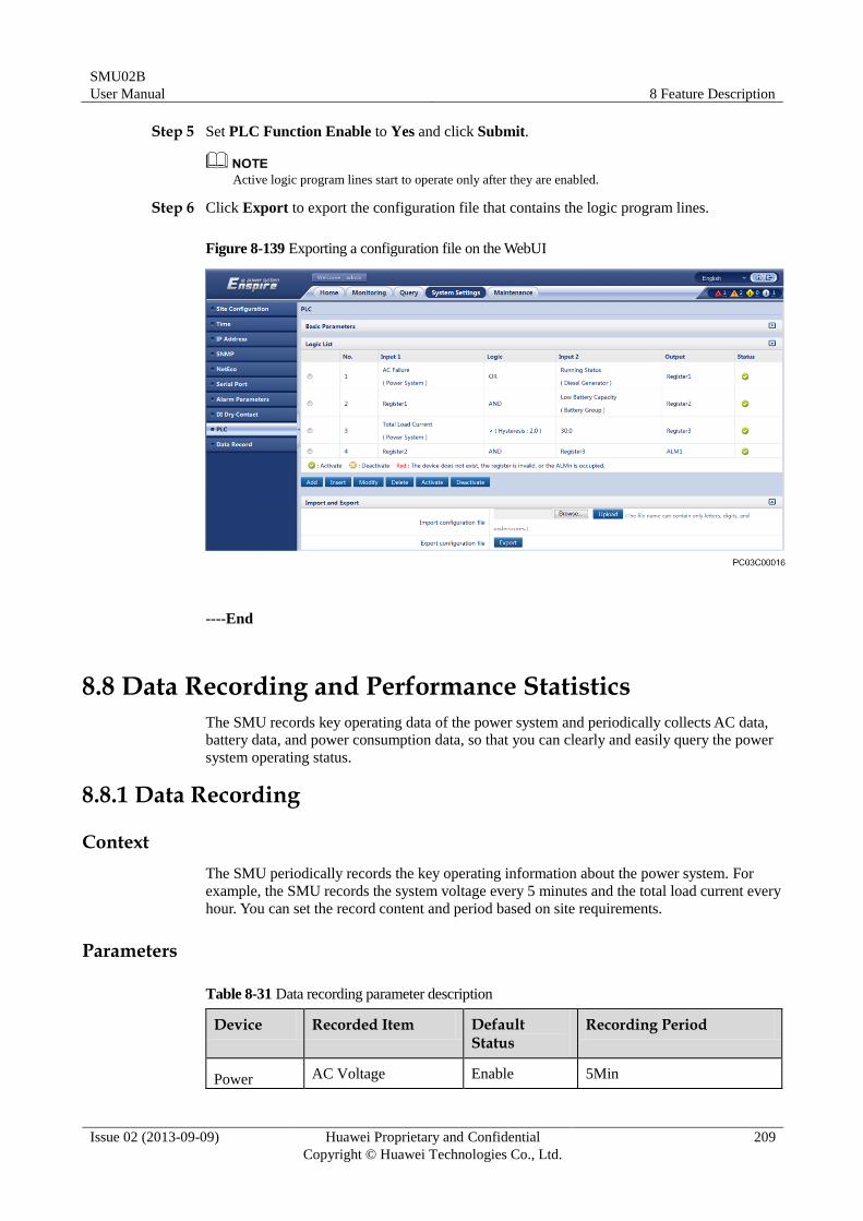
SMU02B
User Manual 8 Feature Description
Issue 02 (2013-09-09) Huawei Proprietary and Confidential
Copyright © Huawei Technologies Co., Ltd.
209
Step 5 Set PLC Function Enable to Yes and click Submit.
Active logic program lines start to operate only after they are enabled.
Step 6 Click Export to export the configuration file that contains the logic program lines.
Figure 8-139 Exporting a configuration file on the WebUI
----End
8.8 Data Recording and Performance Statistics
The SMU records key operating data of the power system and periodically collects AC data,
battery data, and power consumption data, so that you can clearly and easily query the power
system operating status.
8.8.1 Data Recording
Context
The SMU periodically records the key operating information about the power system. For
example, the SMU records the system voltage every 5 minutes and the total load current every
hour. You can set the record content and period based on site requirements.
Parameters
Table 8-31 Data recording parameter description
Device Recorded Item Default Status
Recording Period
Power AC Voltage Enable 5Min
SMU02B
User Manual 8 Feature Description
Issue 02 (2013-09-09) Huawei Proprietary and Confidential
Copyright © Huawei Technologies Co., Ltd.
210
Device Recorded Item Default Status
Recording Period
System
Power
System
Phase L1 Voltage Enable 5Min
Power
System
Phase L2 Voltage Enable 5Min
Power
System
Phase L3 Voltage Enable 5Min
Power
System System Voltage Enable 5Min
Power
System
Total Load Current Enable 5Min
Power
System
Ambient Temperature Disable 5Min
Power
System
Ambient Humidity Disable 5Min
Power
System
Power Supply Status Enable Status Change
Battery
Group
Battery Temperature Enable 5Min
Battery
Group
Battery Status Enable Status Change
Battery
Group
Total Battery Current Enable 5Min
Battery
Group
Remaining Capacity
Percent
Enable 5Min
Battery
String1
Battery Current Enable 5Min
Battery
String2
Battery Current Enable 5Min
Battery
Group
Fan 1 Speed Disable 5Min
Battery
Group
Fan 2 Speed Disable 5Min
Battery
Group
Fan 3 Speed Disable 5Min
Battery
Group
Fan 4 Speed Disable 5Min
AC Air Device Status Enable Status Change
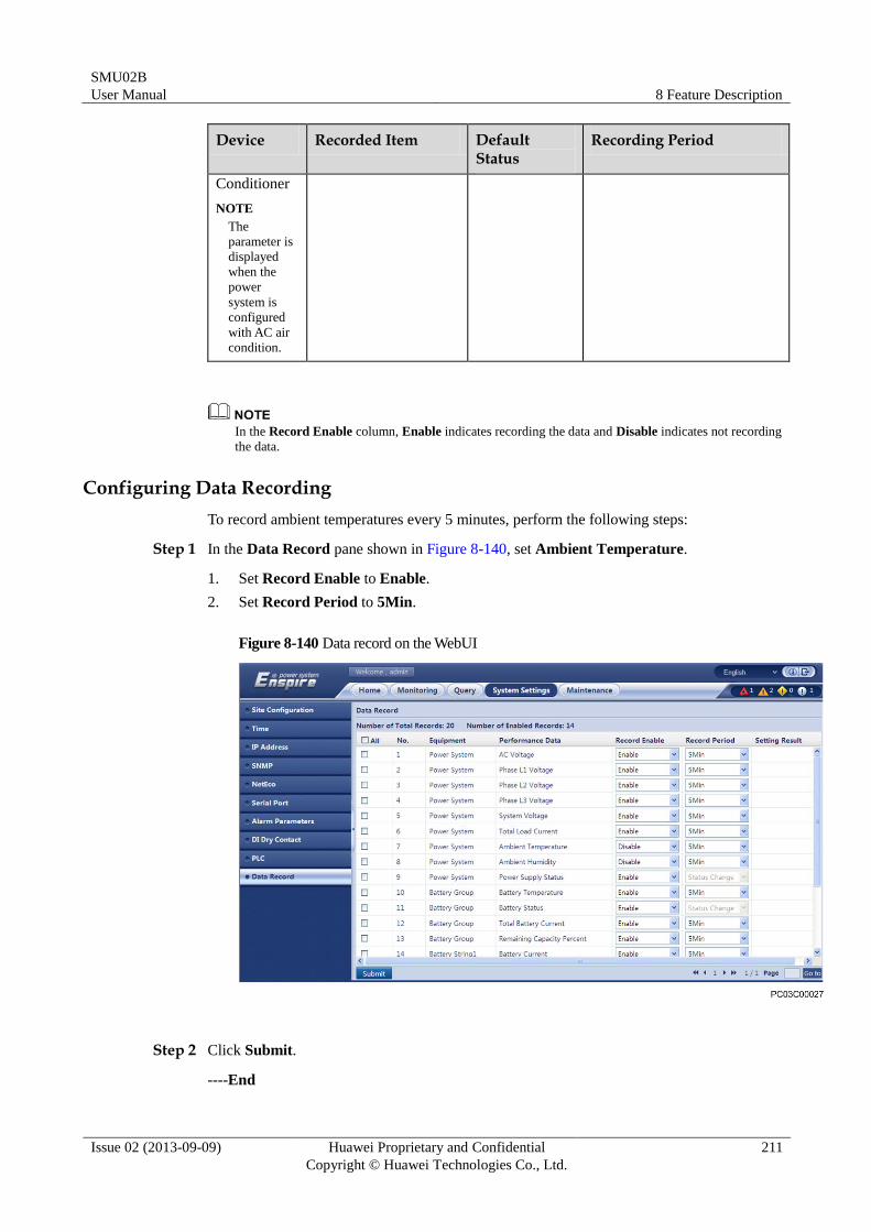
SMU02B
User Manual 8 Feature Description
Issue 02 (2013-09-09) Huawei Proprietary and Confidential
Copyright © Huawei Technologies Co., Ltd.
211
Device Recorded Item Default Status
Recording Period
Conditioner
NOTE
The
parameter is
displayed
when the
power
system is
configured
with AC air
condition.
In the Record Enable column, Enable indicates recording the data and Disable indicates not recording
the data.
Configuring Data Recording
To record ambient temperatures every 5 minutes, perform the following steps:
Step 1 In the Data Record pane shown in Figure 8-140, set Ambient Temperature.
1. Set Record Enable to Enable.
2. Set Record Period to 5Min.
Figure 8-140 Data record on the WebUI
Step 2 Click Submit.
----End
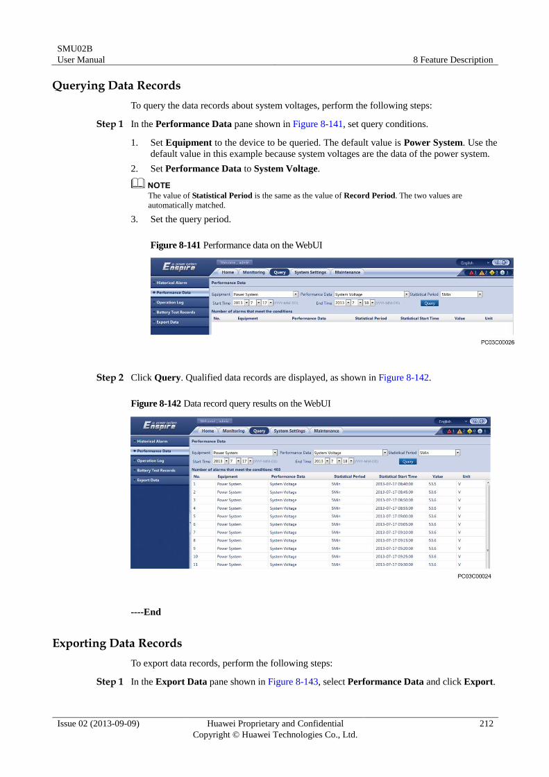
SMU02B
User Manual 8 Feature Description
Issue 02 (2013-09-09) Huawei Proprietary and Confidential
Copyright © Huawei Technologies Co., Ltd.
212
Querying Data Records
To query the data records about system voltages, perform the following steps:
Step 1 In the Performance Data pane shown in Figure 8-141, set query conditions.
1. Set Equipment to the device to be queried. The default value is Power System. Use the
default value in this example because system voltages are the data of the power system.
2. Set Performance Data to System Voltage.
The value of Statistical Period is the same as the value of Record Period. The two values are
automatically matched.
3. Set the query period.
Figure 8-141 Performance data on the WebUI
Step 2 Click Query. Qualified data records are displayed, as shown in Figure 8-142.
Figure 8-142 Data record query results on the WebUI
----End
Exporting Data Records
To export data records, perform the following steps:
Step 1 In the Export Data pane shown in Figure 8-143, select Performance Data and click Export.
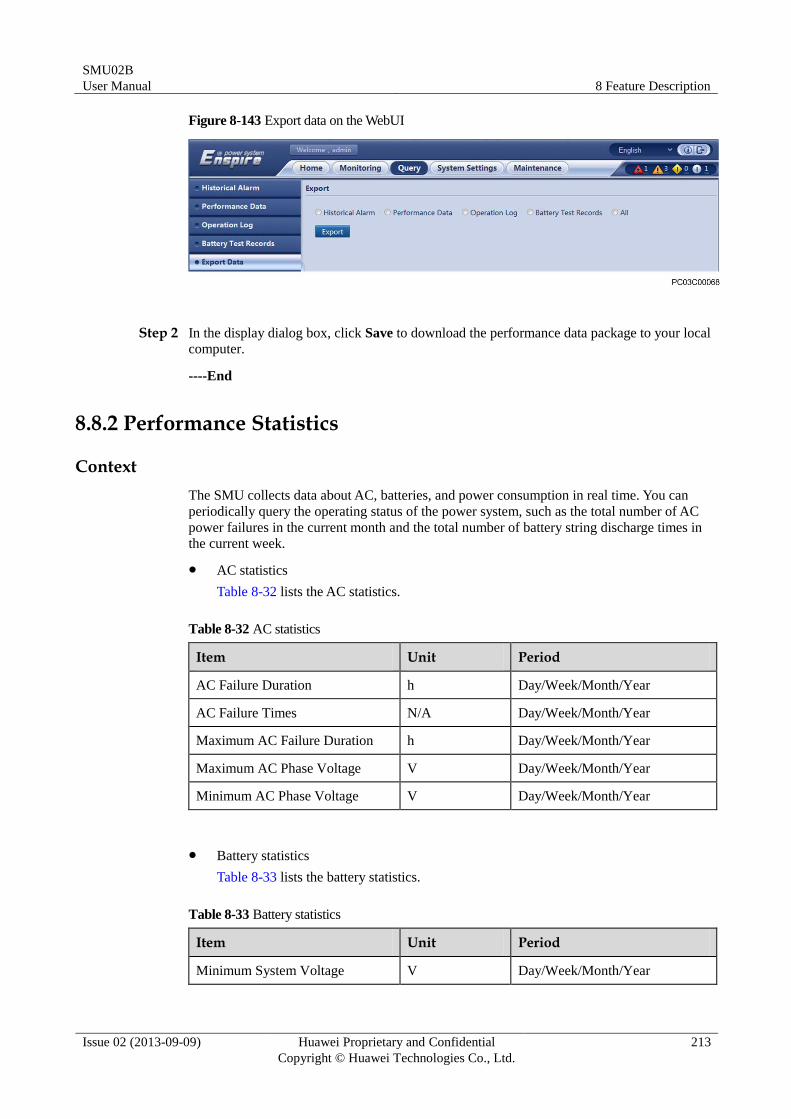
SMU02B
User Manual 8 Feature Description
Issue 02 (2013-09-09) Huawei Proprietary and Confidential
Copyright © Huawei Technologies Co., Ltd.
213
Figure 8-143 Export data on the WebUI
Step 2 In the display dialog box, click Save to download the performance data package to your local
computer.
----End
8.8.2 Performance Statistics
Context
The SMU collects data about AC, batteries, and power consumption in real time. You can
periodically query the operating status of the power system, such as the total number of AC
power failures in the current month and the total number of battery string discharge times in
the current week.
AC statistics
Table 8-32 lists the AC statistics.
Table 8-32 AC statistics
Item Unit Period
AC Failure Duration h Day/Week/Month/Year
AC Failure Times N/A Day/Week/Month/Year
Maximum AC Failure Duration h Day/Week/Month/Year
Maximum AC Phase Voltage V Day/Week/Month/Year
Minimum AC Phase Voltage V Day/Week/Month/Year
Battery statistics
Table 8-33 lists the battery statistics.
Table 8-33 Battery statistics
Item Unit Period
Minimum System Voltage V Day/Week/Month/Year
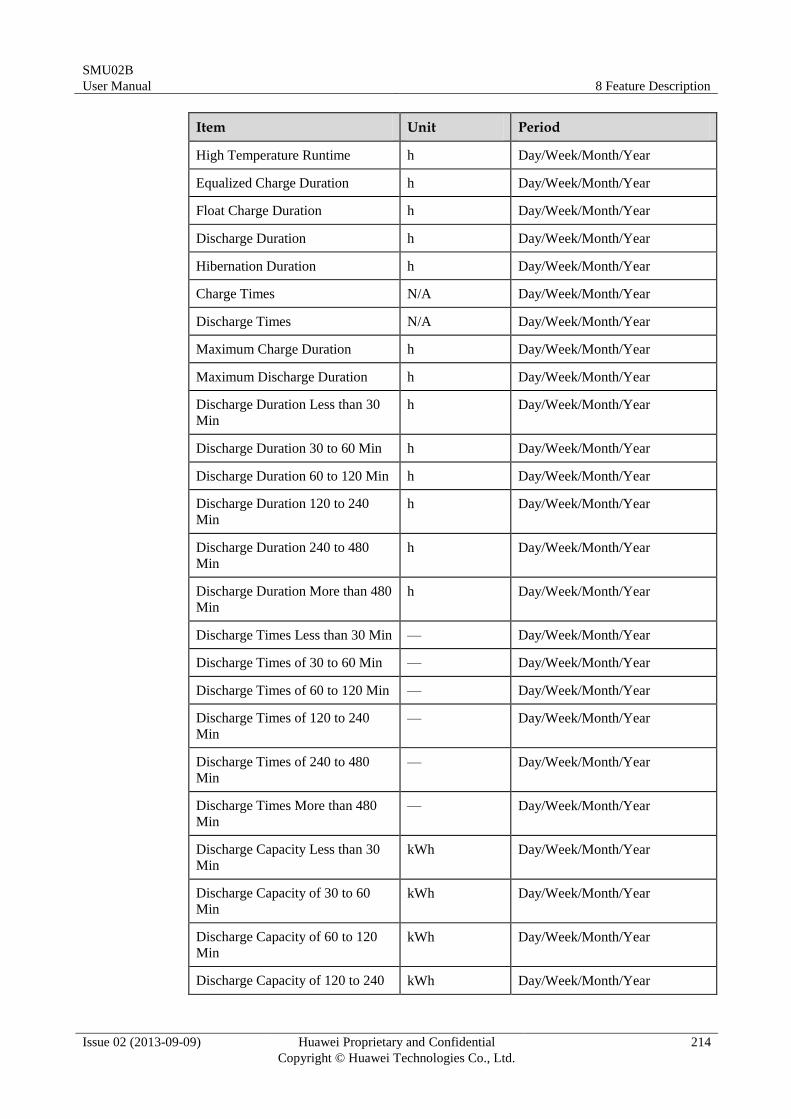
SMU02B
User Manual 8 Feature Description
Issue 02 (2013-09-09) Huawei Proprietary and Confidential
Copyright © Huawei Technologies Co., Ltd.
214
Item Unit Period
High Temperature Runtime h Day/Week/Month/Year
Equalized Charge Duration h Day/Week/Month/Year
Float Charge Duration h Day/Week/Month/Year
Discharge Duration h Day/Week/Month/Year
Hibernation Duration h Day/Week/Month/Year
Charge Times N/A Day/Week/Month/Year
Discharge Times N/A Day/Week/Month/Year
Maximum Charge Duration h Day/Week/Month/Year
Maximum Discharge Duration h Day/Week/Month/Year
Discharge Duration Less than 30
Min
h Day/Week/Month/Year
Discharge Duration 30 to 60 Min h Day/Week/Month/Year
Discharge Duration 60 to 120 Min h Day/Week/Month/Year
Discharge Duration 120 to 240
Min
h Day/Week/Month/Year
Discharge Duration 240 to 480
Min
h Day/Week/Month/Year
Discharge Duration More than 480
Min
h Day/Week/Month/Year
Discharge Times Less than 30 Min — Day/Week/Month/Year
Discharge Times of 30 to 60 Min — Day/Week/Month/Year
Discharge Times of 60 to 120 Min — Day/Week/Month/Year
Discharge Times of 120 to 240
Min
— Day/Week/Month/Year
Discharge Times of 240 to 480
Min
— Day/Week/Month/Year
Discharge Times More than 480
Min
— Day/Week/Month/Year
Discharge Capacity Less than 30
Min
kWh Day/Week/Month/Year
Discharge Capacity of 30 to 60
Min
kWh Day/Week/Month/Year
Discharge Capacity of 60 to 120
Min
kWh Day/Week/Month/Year
Discharge Capacity of 120 to 240 kWh Day/Week/Month/Year
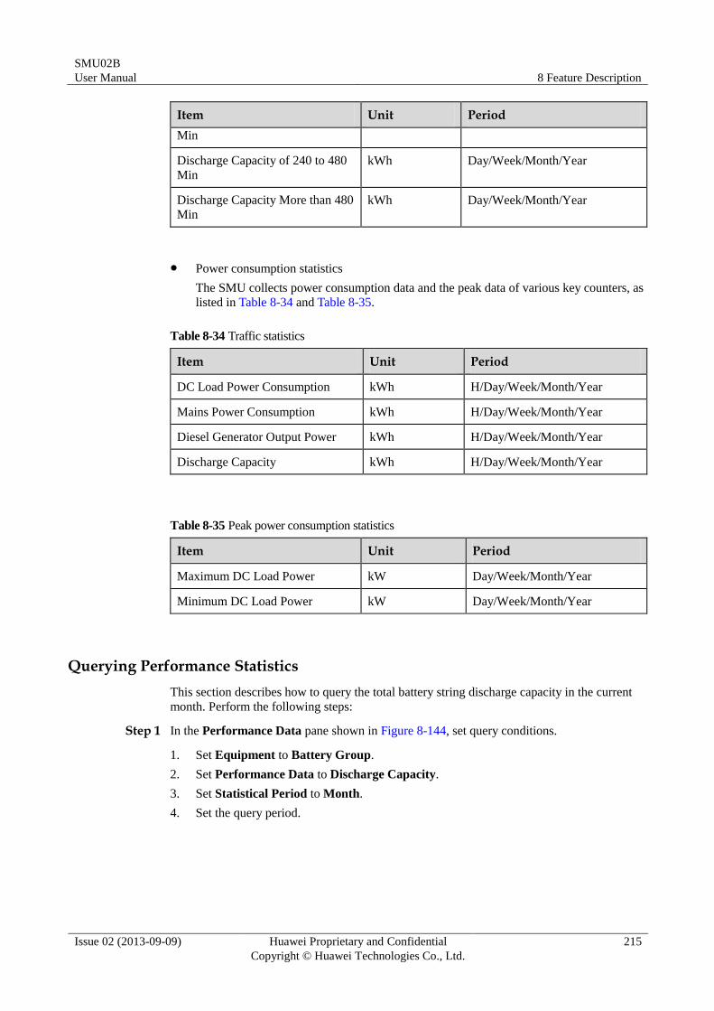
SMU02B
User Manual 8 Feature Description
Issue 02 (2013-09-09) Huawei Proprietary and Confidential
Copyright © Huawei Technologies Co., Ltd.
215
Item Unit Period
Min
Discharge Capacity of 240 to 480
Min
kWh Day/Week/Month/Year
Discharge Capacity More than 480
Min
kWh Day/Week/Month/Year
Power consumption statistics
The SMU collects power consumption data and the peak data of various key counters, as
listed in Table 8-34 and Table 8-35.
Table 8-34 Traffic statistics
Item Unit Period
DC Load Power Consumption kWh H/Day/Week/Month/Year
Mains Power Consumption kWh H/Day/Week/Month/Year
Diesel Generator Output Power kWh H/Day/Week/Month/Year
Discharge Capacity kWh H/Day/Week/Month/Year
Table 8-35 Peak power consumption statistics
Item Unit Period
Maximum DC Load Power kW Day/Week/Month/Year
Minimum DC Load Power kW Day/Week/Month/Year
Querying Performance Statistics
This section describes how to query the total battery string discharge capacity in the current
month. Perform the following steps:
Step 1 In the Performance Data pane shown in Figure 8-144, set query conditions.
1. Set Equipment to Battery Group.
2. Set Performance Data to Discharge Capacity.
3. Set Statistical Period to Month.
4. Set the query period.
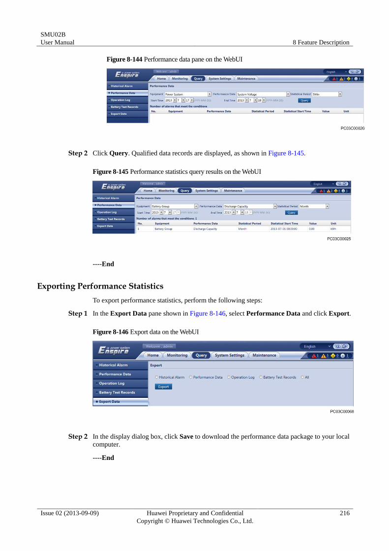
SMU02B
User Manual 8 Feature Description
Issue 02 (2013-09-09) Huawei Proprietary and Confidential
Copyright © Huawei Technologies Co., Ltd.
216
Figure 8-144 Performance data pane on the WebUI
Step 2 Click Query. Qualified data records are displayed, as shown in Figure 8-145.
Figure 8-145 Performance statistics query results on the WebUI
----End
Exporting Performance Statistics
To export performance statistics, perform the following steps:
Step 1 In the Export Data pane shown in Figure 8-146, select Performance Data and click Export.
Figure 8-146 Export data on the WebUI
Step 2 In the display dialog box, click Save to download the performance data package to your local
computer.
----End
SMU02B
User Manual A LCD Menu Hierarchy
Issue 02 (2013-09-09) Huawei Proprietary and Confidential
Copyright © Huawei Technologies Co., Ltd.
217
A LCD Menu Hierarchy
The menu hierarchy and parameter display depend on the system type, parameter settings, and device
connections.
Table A-1 Running Information menu hierarchy
Second-Level Menu Third-Level Menu Fourth-Level Menu
Power System Basic Information System Voltage
Total Load Current
Phase L1 Voltage
Phase L2 Voltage
Phase L3 Voltage
Phase L1 Current
Phase L2 Current
Phase L3 Current
AC Frequency
DO Control Status ALM1 Control Status
ALM2 Control Status
ALM3 Control Status
ALM4 Control Status
ALM5 Control Status
ALM6 Control Status
ALM7 Control Status
ALM8 Control Status
ALM9 Control Status
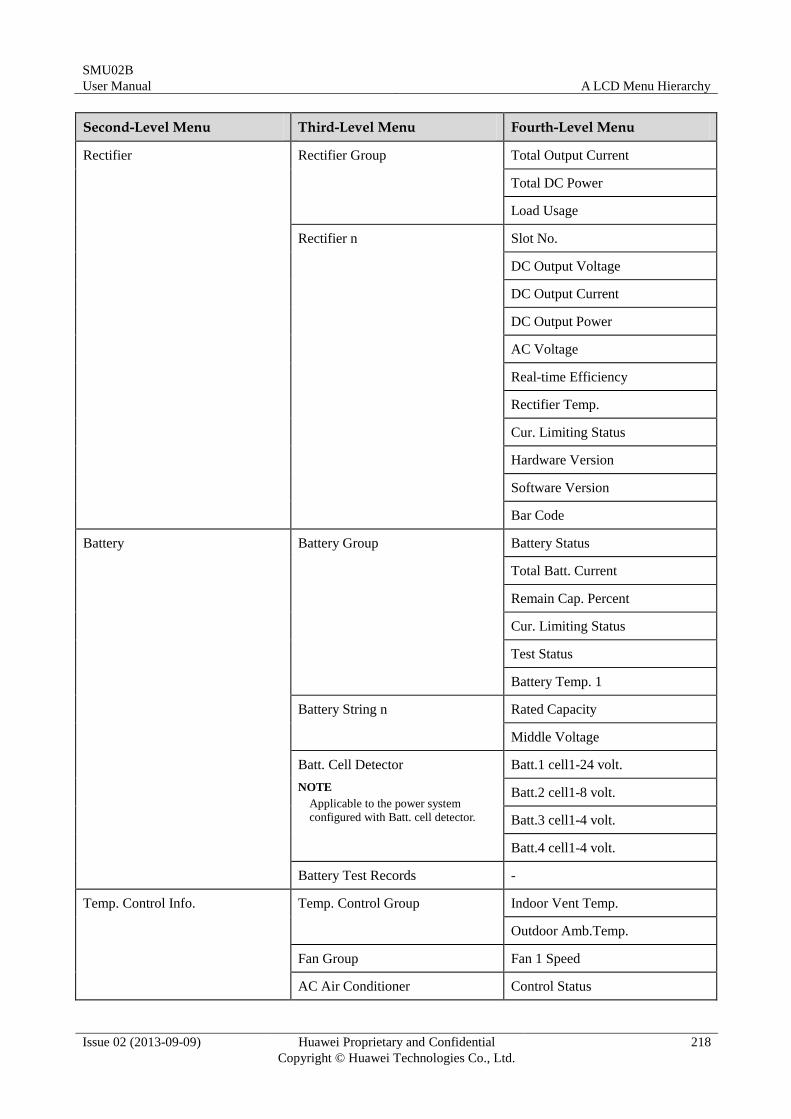
SMU02B
User Manual A LCD Menu Hierarchy
Issue 02 (2013-09-09) Huawei Proprietary and Confidential
Copyright © Huawei Technologies Co., Ltd.
218
Second-Level Menu Third-Level Menu Fourth-Level Menu
Rectifier Rectifier Group Total Output Current
Total DC Power
Load Usage
Rectifier n Slot No.
DC Output Voltage
DC Output Current
DC Output Power
AC Voltage
Real-time Efficiency
Rectifier Temp.
Cur. Limiting Status
Hardware Version
Software Version
Bar Code
Battery Battery Group Battery Status
Total Batt. Current
Remain Cap. Percent
Cur. Limiting Status
Test Status
Battery Temp. 1
Battery String n Rated Capacity
Middle Voltage
Batt. Cell Detector
NOTE
Applicable to the power system
configured with Batt. cell detector.
Batt.1 cell1-24 volt.
Batt.2 cell1-8 volt.
Batt.3 cell1-4 volt.
Batt.4 cell1-4 volt.
Battery Test Records -
Temp. Control Info. Temp. Control Group Indoor Vent Temp.
Outdoor Amb.Temp.
Fan Group Fan 1 Speed
AC Air Conditioner Control Status
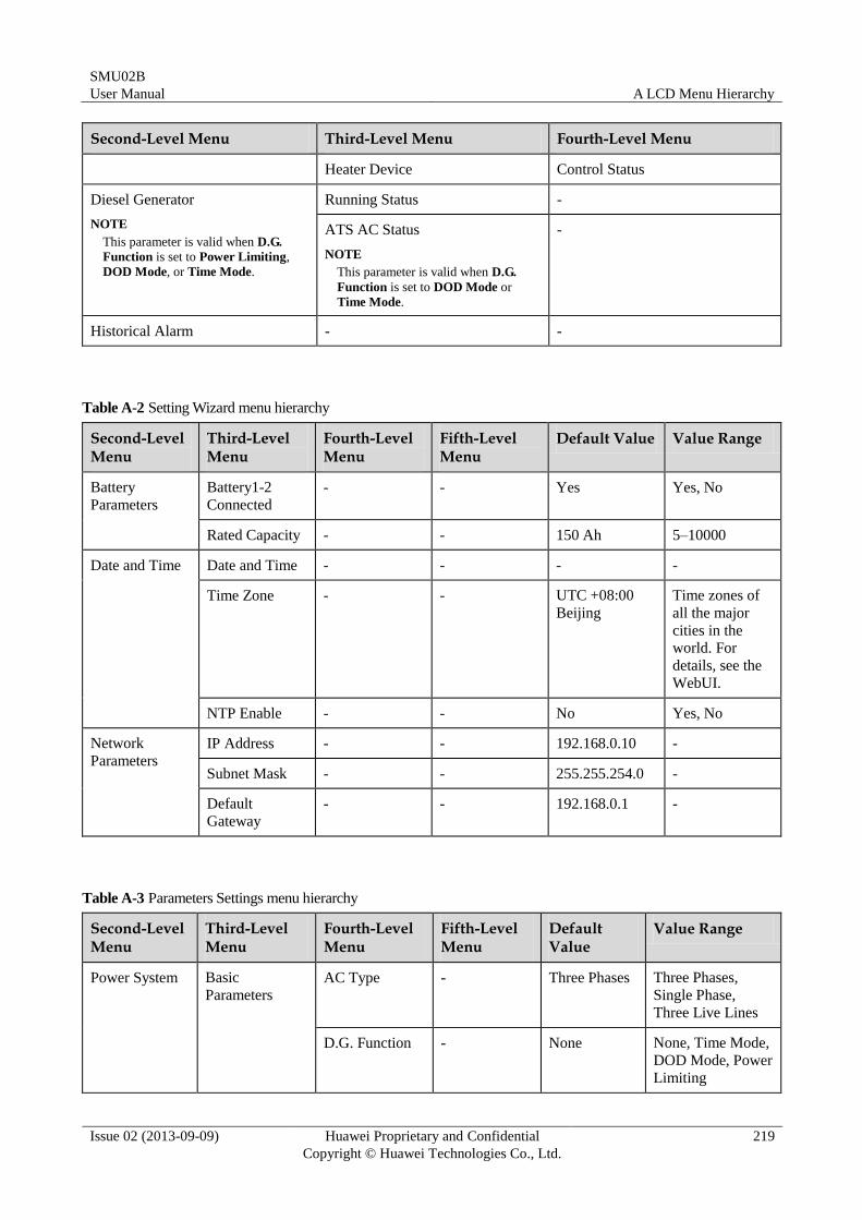
SMU02B
User Manual A LCD Menu Hierarchy
Issue 02 (2013-09-09) Huawei Proprietary and Confidential
Copyright © Huawei Technologies Co., Ltd.
219
Second-Level Menu Third-Level Menu Fourth-Level Menu
Heater Device Control Status
Diesel Generator
NOTE
This parameter is valid when D.G.
Function is set to Power Limiting,
DOD Mode, or Time Mode.
Running Status -
ATS AC Status
NOTE
This parameter is valid when D.G.
Function is set to DOD Mode or
Time Mode.
-
Historical Alarm - -
Table A-2 Setting Wizard menu hierarchy
Second-Level Menu
Third-Level Menu
Fourth-Level Menu
Fifth-Level Menu
Default Value Value Range
Battery
Parameters
Battery1-2
Connected
- - Yes Yes, No
Rated Capacity - - 150 Ah 5–10000
Date and Time Date and Time - - - -
Time Zone - - UTC +08:00
Beijing
Time zones of
all the major
cities in the
world. For
details, see the
WebUI.
NTP Enable - - No Yes, No
Network
Parameters
IP Address - - 192.168.0.10 -
Subnet Mask - - 255.255.254.0 -
Default
Gateway
- - 192.168.0.1 -
Table A-3 Parameters Settings menu hierarchy
Second-Level Menu
Third-Level Menu
Fourth-Level Menu
Fifth-Level Menu
Default Value
Value Range
Power System Basic
Parameters
AC Type - Three Phases Three Phases,
Single Phase,
Three Live Lines
D.G. Function - None None, Time Mode,
DOD Mode, Power
Limiting
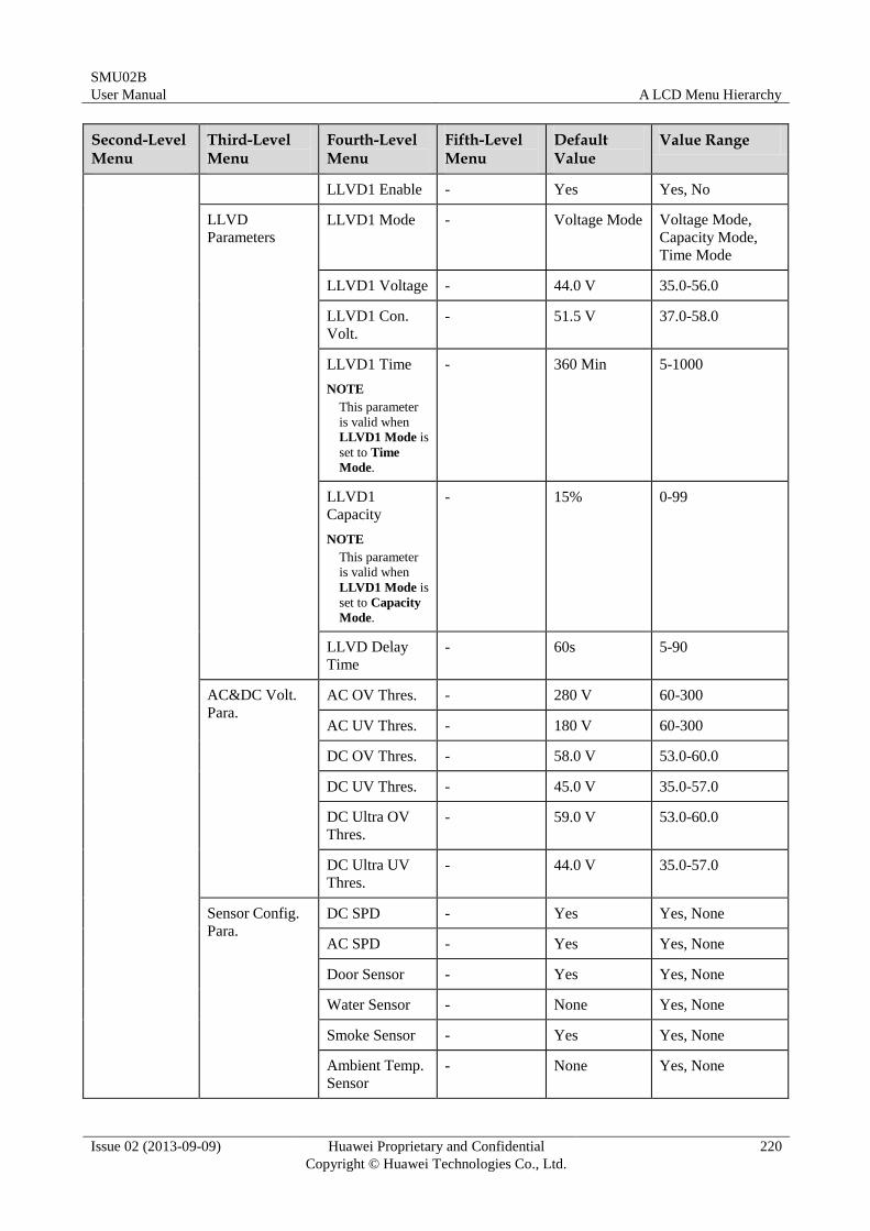
SMU02B
User Manual A LCD Menu Hierarchy
Issue 02 (2013-09-09) Huawei Proprietary and Confidential
Copyright © Huawei Technologies Co., Ltd.
220
Second-Level Menu
Third-Level Menu
Fourth-Level Menu
Fifth-Level Menu
Default Value
Value Range
LLVD1 Enable - Yes Yes, No
LLVD
Parameters
LLVD1 Mode - Voltage Mode Voltage Mode,
Capacity Mode,
Time Mode
LLVD1 Voltage - 44.0 V 35.0-56.0
LLVD1 Con.
Volt.
- 51.5 V 37.0-58.0
LLVD1 Time
NOTE
This parameter
is valid when
LLVD1 Mode is
set to Time
Mode.
- 360 Min 5-1000
LLVD1
Capacity
NOTE
This parameter
is valid when
LLVD1 Mode is
set to Capacity
Mode.
- 15% 0-99
LLVD Delay
Time
- 60s 5-90
AC&DC Volt.
Para.
AC OV Thres. - 280 V 60-300
AC UV Thres. - 180 V 60-300
DC OV Thres. - 58.0 V 53.0-60.0
DC UV Thres. - 45.0 V 35.0-57.0
DC Ultra OV
Thres.
- 59.0 V 53.0-60.0
DC Ultra UV
Thres.
- 44.0 V 35.0-57.0
Sensor Config.
Para.
DC SPD - Yes Yes, None
AC SPD - Yes Yes, None
Door Sensor - Yes Yes, None
Water Sensor - None Yes, None
Smoke Sensor - Yes Yes, None
Ambient Temp.
Sensor - None Yes, None
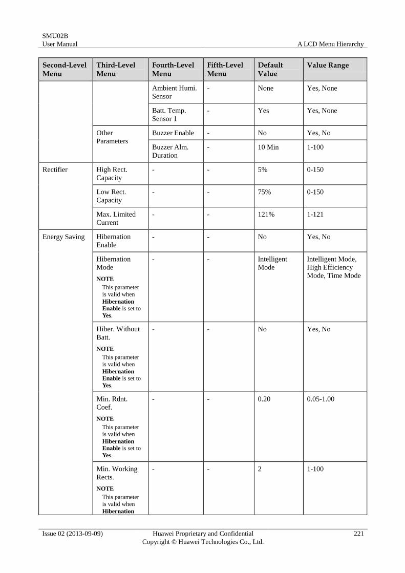
SMU02B
User Manual A LCD Menu Hierarchy
Issue 02 (2013-09-09) Huawei Proprietary and Confidential
Copyright © Huawei Technologies Co., Ltd.
221
Second-Level Menu
Third-Level Menu
Fourth-Level Menu
Fifth-Level Menu
Default Value
Value Range
Ambient Humi.
Sensor
- None Yes, None
Batt. Temp.
Sensor 1
- Yes Yes, None
Other
Parameters
Buzzer Enable - No Yes, No
Buzzer Alm.
Duration
- 10 Min 1-100
Rectifier High Rect.
Capacity
- - 5% 0-150
Low Rect.
Capacity
- - 75% 0-150
Max. Limited
Current
- - 121% 1-121
Energy Saving Hibernation
Enable
- - No Yes, No
Hibernation
Mode
NOTE
This parameter
is valid when
Hibernation
Enable is set to
Yes.
- - Intelligent
Mode
Intelligent Mode,
High Efficiency
Mode, Time Mode
Hiber. Without
Batt.
NOTE
This parameter
is valid when
Hibernation
Enable is set to
Yes.
- - No Yes, No
Min. Rdnt.
Coef.
NOTE
This parameter
is valid when
Hibernation
Enable is set to
Yes.
- - 0.20 0.05-1.00
Min. Working
Rects.
NOTE
This parameter
is valid when
Hibernation
- - 2 1-100
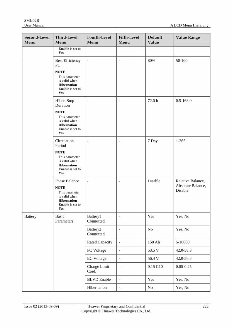
SMU02B
User Manual A LCD Menu Hierarchy
Issue 02 (2013-09-09) Huawei Proprietary and Confidential
Copyright © Huawei Technologies Co., Ltd.
222
Second-Level Menu
Third-Level Menu
Fourth-Level Menu
Fifth-Level Menu
Default Value
Value Range
Enable is set to
Yes.
Best Efficiency
Pt.
NOTE
This parameter
is valid when
Hibernation
Enable is set to
Yes.
- - 80% 50-100
Hiber. Stop
Duration
NOTE
This parameter
is valid when
Hibernation
Enable is set to
Yes.
- - 72.0 h 0.5-168.0
Circulation
Period
NOTE
This parameter
is valid when
Hibernation
Enable is set to
Yes.
- - 7 Day 1-365
Phase Balance
NOTE
This parameter
is valid when
Hibernation
Enable is set to
Yes.
- - Disable Relative Balance,
Absolute Balance,
Disable
Battery Basic
Parameters
Battery1
Connected
- Yes Yes, No
Battery2
Connected
- No Yes, No
Rated Capacity - 150 Ah 5-10000
FC Voltage - 53.5 V 42.0-58.3
EC Voltage - 56.4 V 42.0-58.3
Charge Limit
Coef.
- 0.15 C10 0.05-0.25
BLVD Enable - Yes Yes, No
Hibernation - No Yes, No
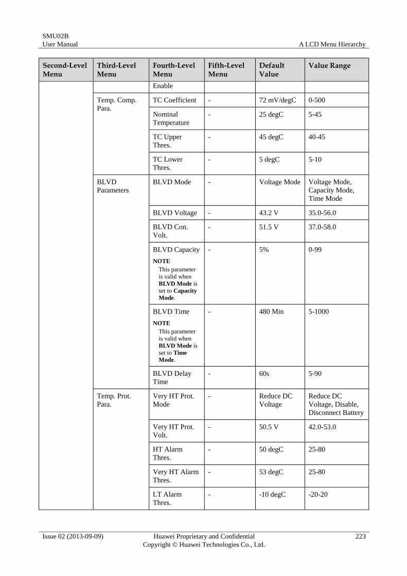
SMU02B
User Manual A LCD Menu Hierarchy
Issue 02 (2013-09-09) Huawei Proprietary and Confidential
Copyright © Huawei Technologies Co., Ltd.
223
Second-Level Menu
Third-Level Menu
Fourth-Level Menu
Fifth-Level Menu
Default Value
Value Range
Enable
Temp. Comp.
Para.
TC Coefficient - 72 mV/degC 0-500
Nominal
Temperature
- 25 degC 5-45
TC Upper
Thres.
- 45 degC 40-45
TC Lower
Thres.
- 5 degC 5-10
BLVD
Parameters
BLVD Mode - Voltage Mode Voltage Mode,
Capacity Mode,
Time Mode
BLVD Voltage - 43.2 V 35.0-56.0
BLVD Con.
Volt.
- 51.5 V 37.0-58.0
BLVD Capacity
NOTE
This parameter
is valid when
BLVD Mode is
set to Capacity
Mode.
- 5% 0-99
BLVD Time
NOTE
This parameter
is valid when
BLVD Mode is
set to Time
Mode.
- 480 Min 5-1000
BLVD Delay
Time
- 60s 5-90
Temp. Prot.
Para.
Very HT Prot.
Mode
- Reduce DC
Voltage
Reduce DC
Voltage, Disable,
Disconnect Battery
Very HT Prot.
Volt.
- 50.5 V 42.0-53.0
HT Alarm
Thres.
- 50 degC 25-80
Very HT Alarm
Thres.
- 53 degC 25-80
LT Alarm
Thres.
- -10 degC -20-20
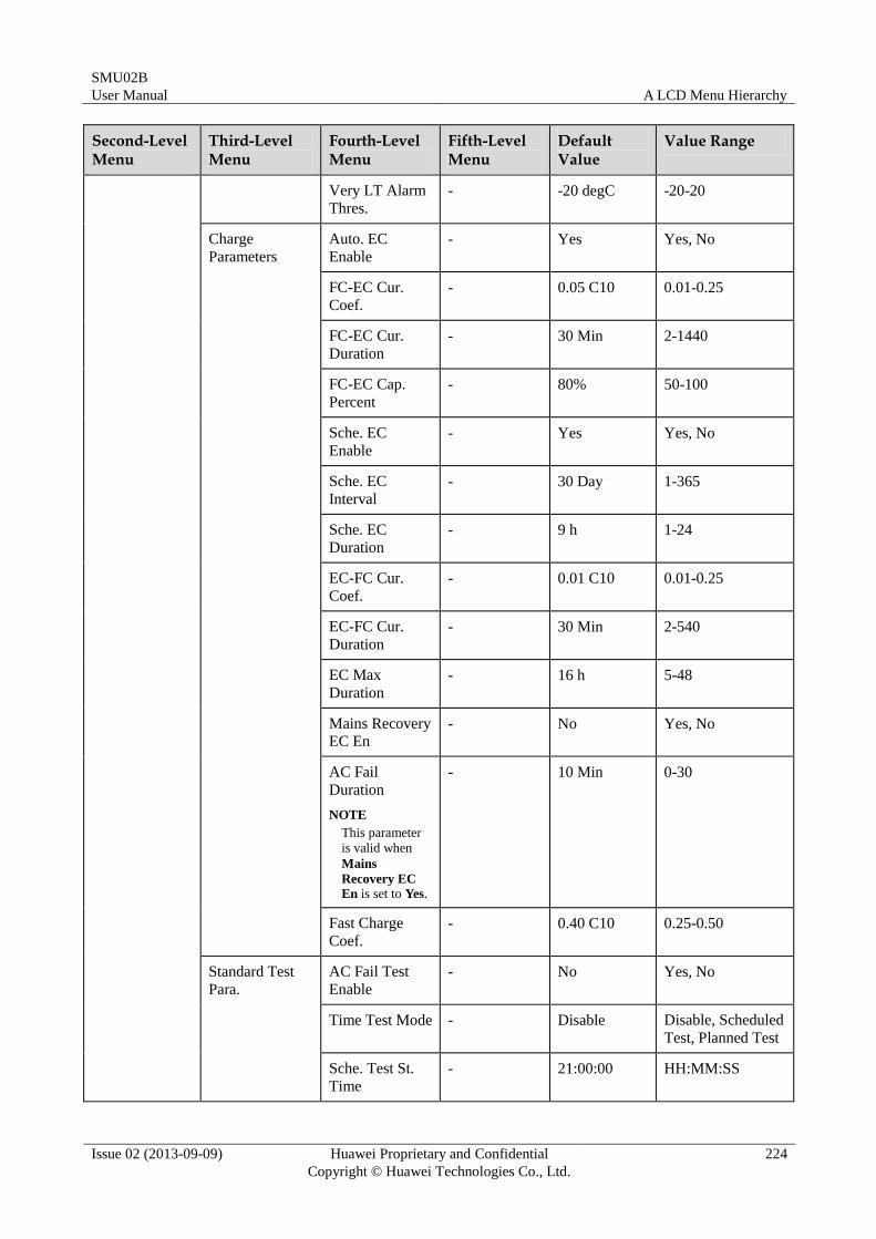
SMU02B
User Manual A LCD Menu Hierarchy
Issue 02 (2013-09-09) Huawei Proprietary and Confidential
Copyright © Huawei Technologies Co., Ltd.
224
Second-Level Menu
Third-Level Menu
Fourth-Level Menu
Fifth-Level Menu
Default Value
Value Range
Very LT Alarm
Thres.
- -20 degC -20-20
Charge
Parameters
Auto. EC
Enable
- Yes Yes, No
FC-EC Cur.
Coef.
- 0.05 C10 0.01-0.25
FC-EC Cur.
Duration
- 30 Min 2-1440
FC-EC Cap.
Percent
- 80% 50-100
Sche. EC
Enable
- Yes Yes, No
Sche. EC
Interval
- 30 Day 1-365
Sche. EC
Duration
- 9 h 1-24
EC-FC Cur.
Coef.
- 0.01 C10 0.01-0.25
EC-FC Cur.
Duration
- 30 Min 2-540
EC Max
Duration
- 16 h 5-48
Mains Recovery
EC En - No Yes, No
AC Fail
Duration
NOTE
This parameter
is valid when
Mains
Recovery EC
En is set to Yes.
- 10 Min 0-30
Fast Charge
Coef.
- 0.40 C10 0.25-0.50
Standard Test
Para.
AC Fail Test
Enable
- No Yes, No
Time Test Mode - Disable Disable, Scheduled
Test, Planned Test
Sche. Test St.
Time
- 21:00:00 HH:MM:SS
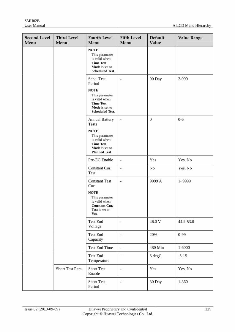
SMU02B
User Manual A LCD Menu Hierarchy
Issue 02 (2013-09-09) Huawei Proprietary and Confidential
Copyright © Huawei Technologies Co., Ltd.
225
Second-Level Menu
Third-Level Menu
Fourth-Level Menu
Fifth-Level Menu
Default Value
Value Range
NOTE
This parameter
is valid when
Time Test
Mode is set to
Scheduled Test.
Sche. Test
Period
NOTE
This parameter
is valid when
Time Test
Mode is set to
Scheduled Test.
- 90 Day 2-999
Annual Battery
Tests
NOTE
This parameter
is valid when
Time Test
Mode is set to
Planned Test
- 0 0-6
Pre-EC Enable - Yes Yes, No
Constant Cur.
Test
- No Yes, No
Constant Test
Cur.
NOTE
This parameter
is valid when
Constant Cur.
Test is set to
Yes.
- 9999 A 1~9999
Test End
Voltage
- 46.0 V 44.2-53.0
Test End
Capacity
- 20% 0-99
Test End Time - 480 Min 1-6000
Test End
Temperature
- 5 degC -5-15
Short Test Para. Short Test
Enable
- Yes Yes, No
Short Test
Period
- 30 Day 1-360
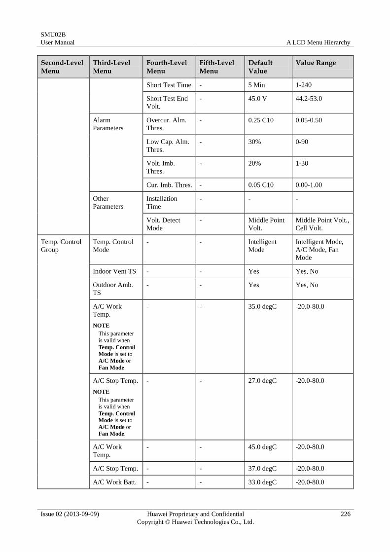
SMU02B
User Manual A LCD Menu Hierarchy
Issue 02 (2013-09-09) Huawei Proprietary and Confidential
Copyright © Huawei Technologies Co., Ltd.
226
Second-Level Menu
Third-Level Menu
Fourth-Level Menu
Fifth-Level Menu
Default Value
Value Range
Short Test Time - 5 Min 1-240
Short Test End
Volt.
- 45.0 V 44.2-53.0
Alarm
Parameters
Overcur. Alm.
Thres.
- 0.25 C10 0.05-0.50
Low Cap. Alm.
Thres.
- 30% 0-90
Volt. Imb.
Thres.
- 20% 1-30
Cur. Imb. Thres. - 0.05 C10 0.00-1.00
Other
Parameters
Installation
Time
- - -
Volt. Detect
Mode
- Middle Point
Volt.
Middle Point Volt.,
Cell Volt.
Temp. Control
Group
Temp. Control
Mode
- - Intelligent
Mode
Intelligent Mode,
A/C Mode, Fan
Mode
Indoor Vent TS - - Yes Yes, No
Outdoor Amb.
TS
- - Yes Yes, No
A/C Work
Temp.
NOTE
This parameter
is valid when
Temp. Control
Mode is set to
A/C Mode or
Fan Mode
- - 35.0 degC -20.0-80.0
A/C Stop Temp.
NOTE
This parameter
is valid when
Temp. Control
Mode is set to
A/C Mode or
Fan Mode.
- - 27.0 degC -20.0-80.0
A/C Work
Temp.
- - 45.0 degC -20.0-80.0
A/C Stop Temp. - - 37.0 degC -20.0-80.0
A/C Work Batt. - - 33.0 degC -20.0-80.0
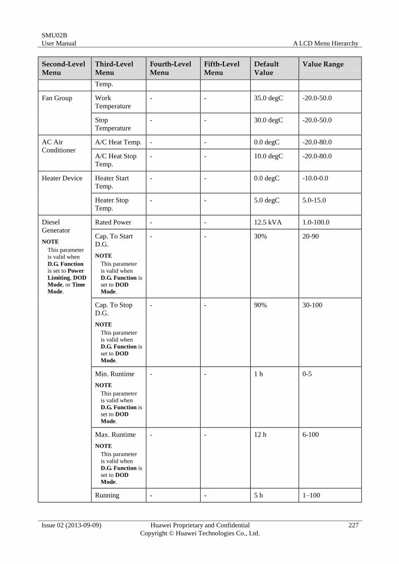
SMU02B
User Manual A LCD Menu Hierarchy
Issue 02 (2013-09-09) Huawei Proprietary and Confidential
Copyright © Huawei Technologies Co., Ltd.
227
Second-Level Menu
Third-Level Menu
Fourth-Level Menu
Fifth-Level Menu
Default Value
Value Range
Temp.
Fan Group Work
Temperature
- - 35.0 degC -20.0-50.0
Stop
Temperature
- - 30.0 degC -20.0-50.0
AC Air
Conditioner
A/C Heat Temp. - - 0.0 degC -20.0-80.0
A/C Heat Stop
Temp.
- - 10.0 degC -20.0-80.0
Heater Device Heater Start
Temp.
- - 0.0 degC -10.0-0.0
Heater Stop
Temp.
- - 5.0 degC 5.0-15.0
Diesel
Generator
NOTE
This parameter
is valid when
D.G. Function is set to Power
Limiting, DOD
Mode, or Time
Mode.
Rated Power - - 12.5 kVA 1.0-100.0
Cap. To Start
D.G.
NOTE
This parameter
is valid when
D.G. Function is
set to DOD
Mode.
- - 30% 20-90
Cap. To Stop
D.G.
NOTE
This parameter
is valid when
D.G. Function is
set to DOD
Mode.
- - 90% 30-100
Min. Runtime
NOTE
This parameter
is valid when
D.G. Function is
set to DOD
Mode.
- - 1 h 0-5
Max. Runtime
NOTE
This parameter
is valid when
D.G. Function is
set to DOD
Mode.
- - 12 h 6-100
Running - - 5 h 1–100
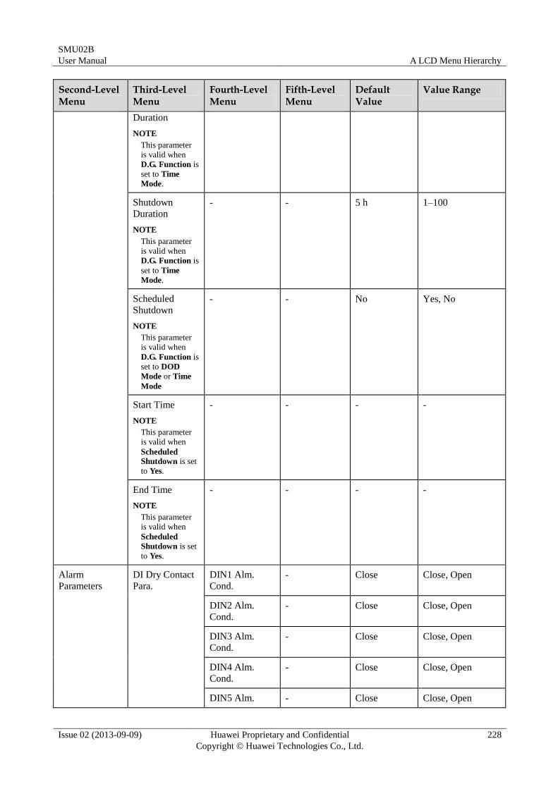
SMU02B
User Manual A LCD Menu Hierarchy
Issue 02 (2013-09-09) Huawei Proprietary and Confidential
Copyright © Huawei Technologies Co., Ltd.
228
Second-Level Menu
Third-Level Menu
Fourth-Level Menu
Fifth-Level Menu
Default Value
Value Range
Duration
NOTE
This parameter
is valid when
D.G. Function is
set to Time
Mode.
Shutdown
Duration
NOTE
This parameter
is valid when
D.G. Function is
set to Time
Mode.
- - 5 h 1–100
Scheduled
Shutdown
NOTE
This parameter
is valid when
D.G. Function is
set to DOD
Mode or Time
Mode
- - No Yes, No
Start Time
NOTE
This parameter
is valid when
Scheduled
Shutdown is set
to Yes.
- - - -
End Time
NOTE
This parameter
is valid when
Scheduled
Shutdown is set
to Yes.
- - - -
Alarm
Parameters
DI Dry Contact
Para.
DIN1 Alm.
Cond.
- Close Close, Open
DIN2 Alm.
Cond.
- Close Close, Open
DIN3 Alm.
Cond.
- Close Close, Open
DIN4 Alm.
Cond.
- Close Close, Open
DIN5 Alm. - Close Close, Open
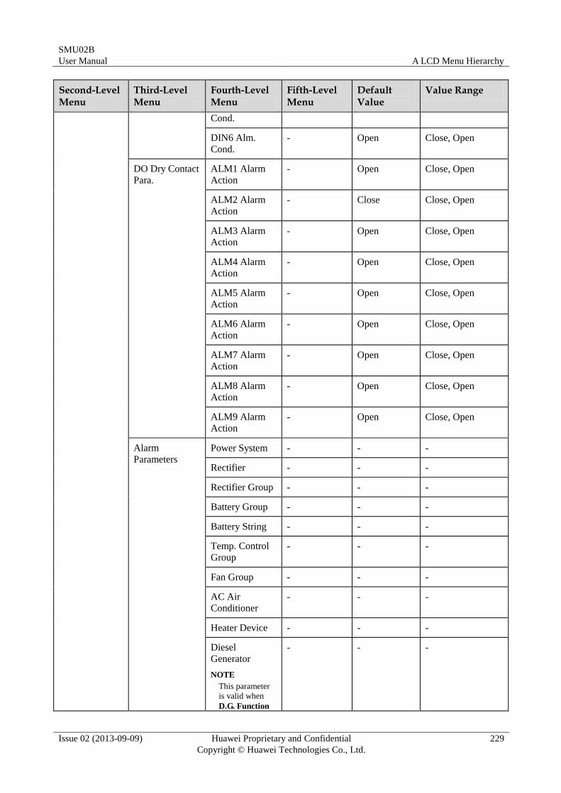
SMU02B
User Manual A LCD Menu Hierarchy
Issue 02 (2013-09-09) Huawei Proprietary and Confidential
Copyright © Huawei Technologies Co., Ltd.
229
Second-Level Menu
Third-Level Menu
Fourth-Level Menu
Fifth-Level Menu
Default Value
Value Range
Cond.
DIN6 Alm.
Cond.
- Open Close, Open
DO Dry Contact
Para.
ALM1 Alarm
Action
- Open Close, Open
ALM2 Alarm
Action
- Close Close, Open
ALM3 Alarm
Action - Open Close, Open
ALM4 Alarm
Action
- Open Close, Open
ALM5 Alarm
Action
- Open Close, Open
ALM6 Alarm
Action
- Open Close, Open
ALM7 Alarm
Action
- Open Close, Open
ALM8 Alarm
Action
- Open Close, Open
ALM9 Alarm
Action
- Open Close, Open
Alarm
Parameters
Power System - - -
Rectifier - - -
Rectifier Group - - -
Battery Group - - -
Battery String - - -
Temp. Control
Group
- - -
Fan Group - - -
AC Air
Conditioner
- - -
Heater Device - - -
Diesel
Generator
NOTE
This parameter
is valid when
D.G. Function
- - -
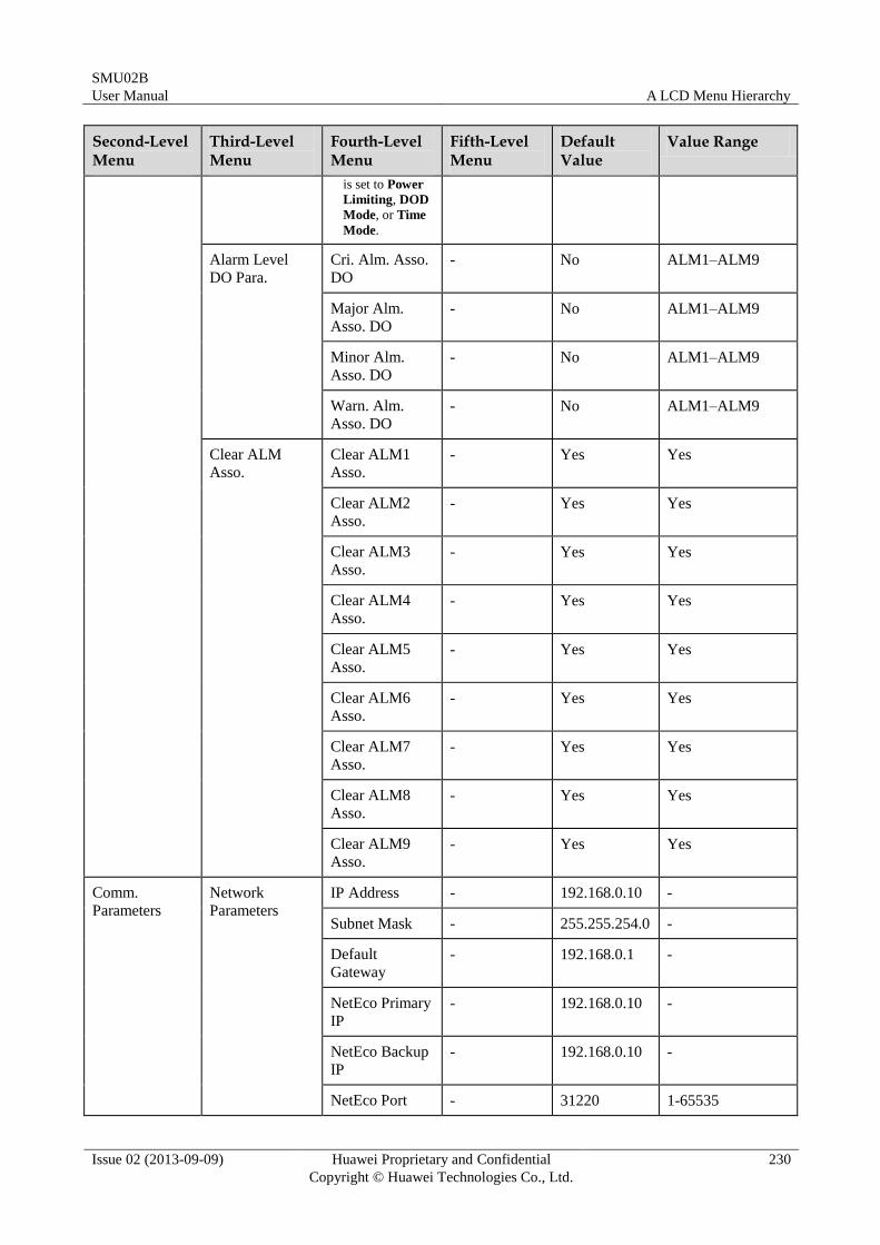
SMU02B
User Manual A LCD Menu Hierarchy
Issue 02 (2013-09-09) Huawei Proprietary and Confidential
Copyright © Huawei Technologies Co., Ltd.
230
Second-Level Menu
Third-Level Menu
Fourth-Level Menu
Fifth-Level Menu
Default Value
Value Range
is set to Power
Limiting, DOD
Mode, or Time
Mode.
Alarm Level
DO Para.
Cri. Alm. Asso.
DO
- No ALM1–ALM9
Major Alm.
Asso. DO
- No ALM1–ALM9
Minor Alm.
Asso. DO
- No ALM1–ALM9
Warn. Alm.
Asso. DO
- No ALM1–ALM9
Clear ALM
Asso.
Clear ALM1
Asso.
- Yes Yes
Clear ALM2
Asso.
- Yes Yes
Clear ALM3
Asso.
- Yes Yes
Clear ALM4
Asso.
- Yes Yes
Clear ALM5
Asso.
- Yes Yes
Clear ALM6
Asso.
- Yes Yes
Clear ALM7
Asso.
- Yes Yes
Clear ALM8
Asso.
- Yes Yes
Clear ALM9
Asso.
- Yes Yes
Comm.
Parameters
Network
Parameters
IP Address - 192.168.0.10 -
Subnet Mask - 255.255.254.0 -
Default
Gateway
- 192.168.0.1 -
NetEco Primary
IP
- 192.168.0.10 -
NetEco Backup
IP
- 192.168.0.10 -
NetEco Port - 31220 1-65535
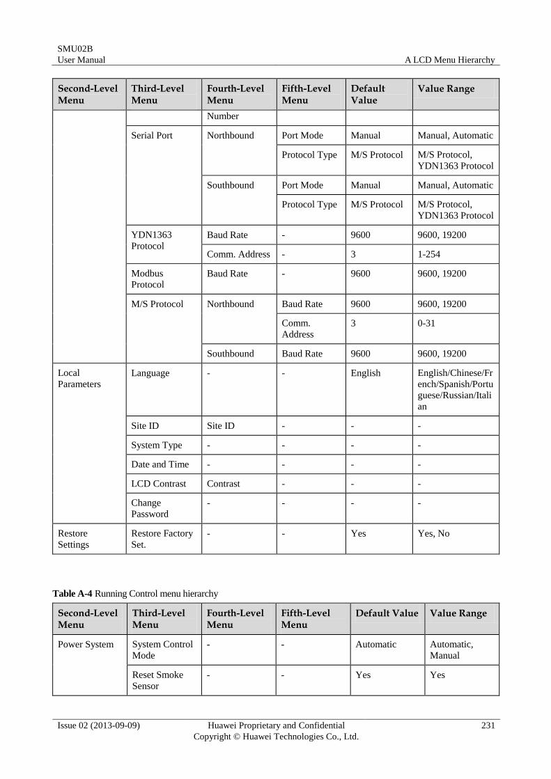
SMU02B
User Manual A LCD Menu Hierarchy
Issue 02 (2013-09-09) Huawei Proprietary and Confidential
Copyright © Huawei Technologies Co., Ltd.
231
Second-Level Menu
Third-Level Menu
Fourth-Level Menu
Fifth-Level Menu
Default Value
Value Range
Number
Serial Port Northbound Port Mode Manual Manual, Automatic
Protocol Type M/S Protocol M/S Protocol,
YDN1363 Protocol
Southbound Port Mode Manual Manual, Automatic
Protocol Type M/S Protocol M/S Protocol,
YDN1363 Protocol
YDN1363
Protocol
Baud Rate - 9600 9600, 19200
Comm. Address - 3 1-254
Modbus
Protocol Baud Rate - 9600 9600, 19200
M/S Protocol Northbound Baud Rate 9600 9600, 19200
Comm.
Address
3 0-31
Southbound Baud Rate 9600 9600, 19200
Local
Parameters
Language - - English English/Chinese/Fr
ench/Spanish/Portu
guese/Russian/Itali
an
Site ID Site ID - - -
System Type - - - -
Date and Time - - - -
LCD Contrast Contrast - - -
Change
Password
- - - -
Restore
Settings
Restore Factory
Set.
- - Yes Yes, No
Table A-4 Running Control menu hierarchy
Second-Level Menu
Third-Level Menu
Fourth-Level Menu
Fifth-Level Menu
Default Value Value Range
Power System System Control
Mode
- - Automatic Automatic,
Manual
Reset Smoke
Sensor - - Yes Yes
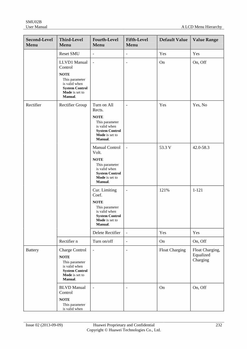
SMU02B
User Manual A LCD Menu Hierarchy
Issue 02 (2013-09-09) Huawei Proprietary and Confidential
Copyright © Huawei Technologies Co., Ltd.
232
Second-Level Menu
Third-Level Menu
Fourth-Level Menu
Fifth-Level Menu
Default Value Value Range
Reset SMU - - Yes Yes
LLVD1 Manual
Control
NOTE
This parameter
is valid when
System Control
Mode is set to
Manual.
- - On On, Off
Rectifier Rectifier Group Turn on All
Rects.
NOTE
This parameter
is valid when
System Control
Mode is set to
Manual.
- Yes Yes, No
Manual Control
Volt.
NOTE
This parameter
is valid when
System Control
Mode is set to
Manual.
- 53.3 V 42.0-58.3
Cur. Limiting
Coef.
NOTE
This parameter
is valid when
System Control
Mode is set to
Manual.
- 121% 1-121
Delete Rectifier - Yes Yes
Rectifier n Turn on/off - On On, Off
Battery Charge Control
NOTE
This parameter
is valid when
System Control
Mode is set to
Manual.
- - Float Charging Float Charging,
Equalized
Charging
BLVD Manual
Control
NOTE
This parameter
is valid when
- - On On, Off
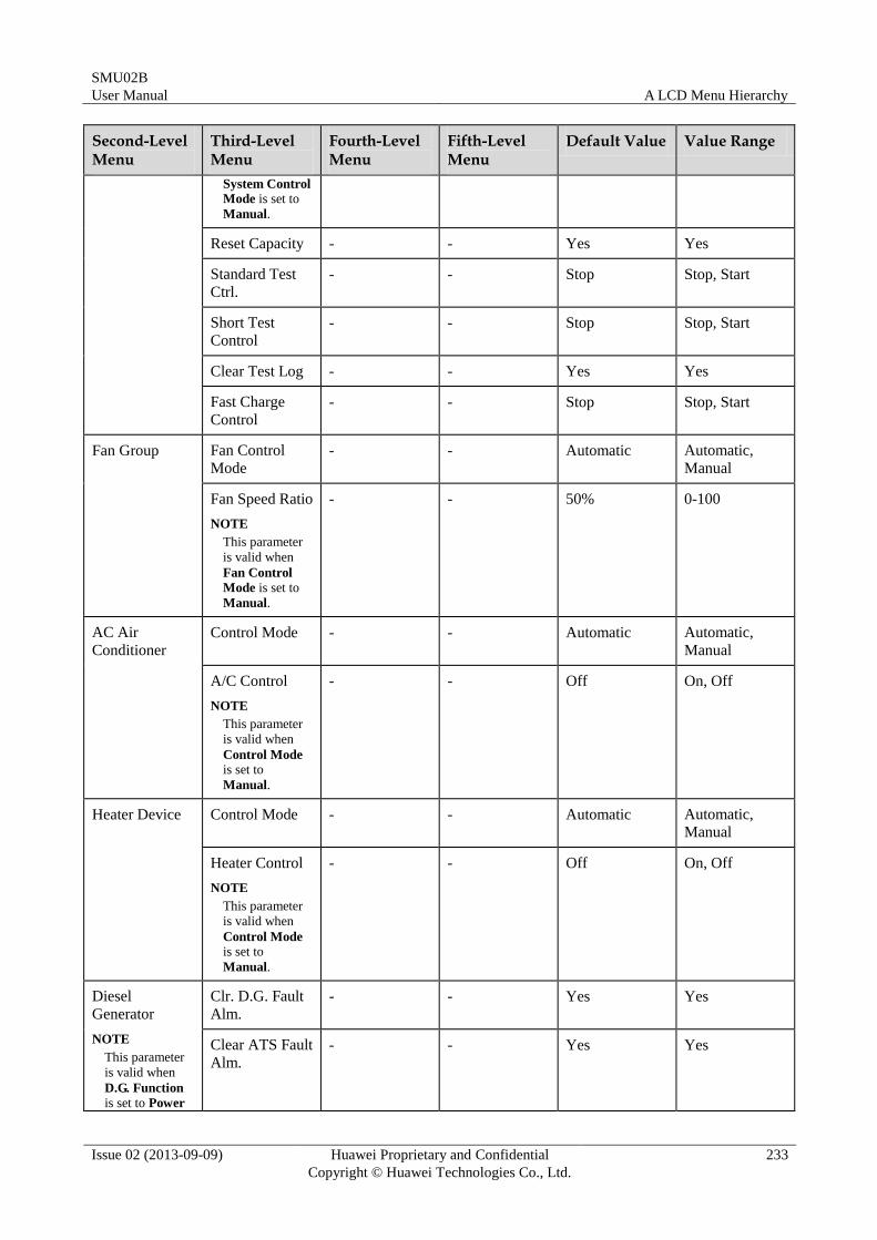
SMU02B
User Manual A LCD Menu Hierarchy
Issue 02 (2013-09-09) Huawei Proprietary and Confidential
Copyright © Huawei Technologies Co., Ltd.
233
Second-Level Menu
Third-Level Menu
Fourth-Level Menu
Fifth-Level Menu
Default Value Value Range
System Control
Mode is set to
Manual.
Reset Capacity - - Yes Yes
Standard Test
Ctrl.
- - Stop Stop, Start
Short Test
Control
- - Stop Stop, Start
Clear Test Log - - Yes Yes
Fast Charge
Control
- - Stop Stop, Start
Fan Group Fan Control
Mode
- - Automatic Automatic,
Manual
Fan Speed Ratio
NOTE
This parameter
is valid when
Fan Control
Mode is set to
Manual.
- - 50% 0-100
AC Air
Conditioner
Control Mode - - Automatic Automatic,
Manual
A/C Control
NOTE
This parameter
is valid when
Control Mode is set to
Manual.
- - Off On, Off
Heater Device Control Mode - - Automatic Automatic,
Manual
Heater Control
NOTE
This parameter
is valid when
Control Mode is set to
Manual.
- - Off On, Off
Diesel
Generator
NOTE
This parameter
is valid when
D.G. Function is set to Power
Clr. D.G. Fault
Alm.
- - Yes Yes
Clear ATS Fault
Alm.
- - Yes Yes
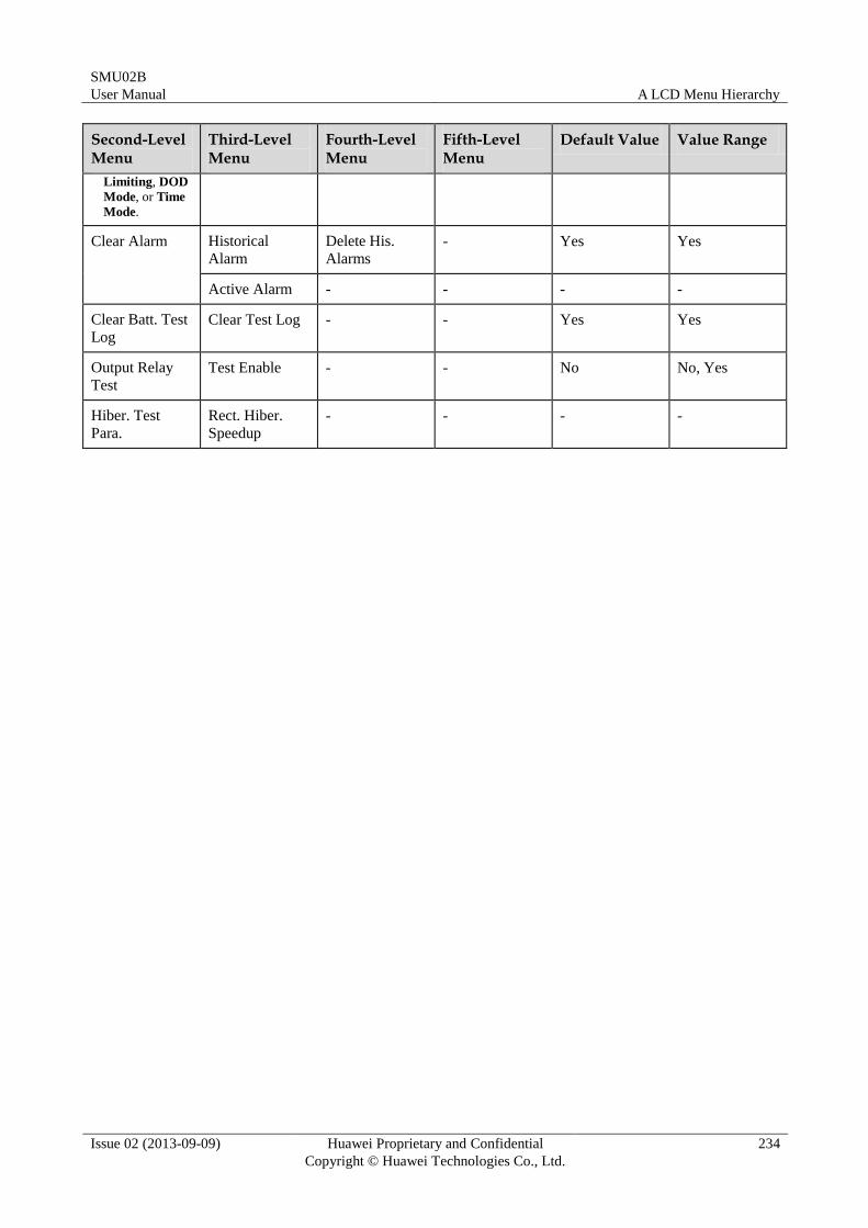
SMU02B
User Manual A LCD Menu Hierarchy
Issue 02 (2013-09-09) Huawei Proprietary and Confidential
Copyright © Huawei Technologies Co., Ltd.
234
Second-Level Menu
Third-Level Menu
Fourth-Level Menu
Fifth-Level Menu
Default Value Value Range
Limiting, DOD
Mode, or Time
Mode.
Clear Alarm Historical
Alarm
Delete His.
Alarms
- Yes Yes
Active Alarm - - - -
Clear Batt. Test
Log
Clear Test Log - - Yes Yes
Output Relay
Test
Test Enable - - No No, Yes
Hiber. Test
Para.
Rect. Hiber.
Speedup
- - - -
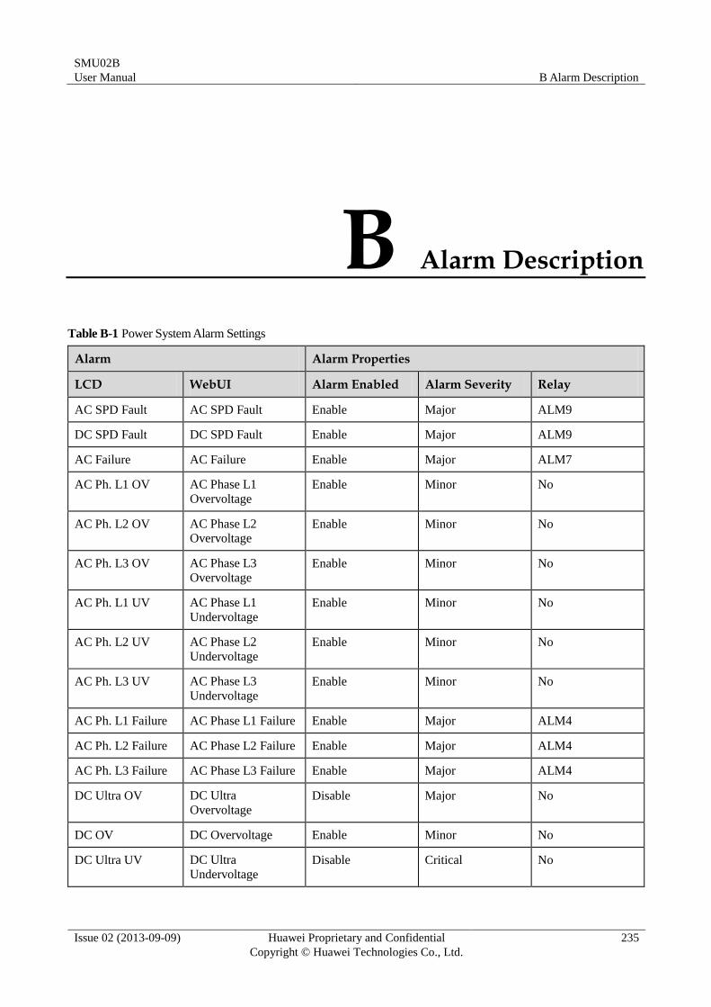
SMU02B
User Manual B Alarm Description
Issue 02 (2013-09-09) Huawei Proprietary and Confidential
Copyright © Huawei Technologies Co., Ltd.
235
B Alarm Description
Table B-1 Power System Alarm Settings
Alarm Alarm Properties
LCD WebUI Alarm Enabled Alarm Severity Relay
AC SPD Fault AC SPD Fault Enable Major ALM9
DC SPD Fault DC SPD Fault Enable Major ALM9
AC Failure AC Failure Enable Major ALM7
AC Ph. L1 OV AC Phase L1
Overvoltage
Enable Minor No
AC Ph. L2 OV AC Phase L2
Overvoltage Enable Minor No
AC Ph. L3 OV AC Phase L3
Overvoltage
Enable Minor No
AC Ph. L1 UV AC Phase L1
Undervoltage
Enable Minor No
AC Ph. L2 UV AC Phase L2
Undervoltage
Enable Minor No
AC Ph. L3 UV AC Phase L3
Undervoltage
Enable Minor No
AC Ph. L1 Failure AC Phase L1 Failure Enable Major ALM4
AC Ph. L2 Failure AC Phase L2 Failure Enable Major ALM4
AC Ph. L3 Failure AC Phase L3 Failure Enable Major ALM4
DC Ultra OV DC Ultra
Overvoltage
Disable Major No
DC OV DC Overvoltage Enable Minor No
DC Ultra UV DC Ultra
Undervoltage
Disable Critical No
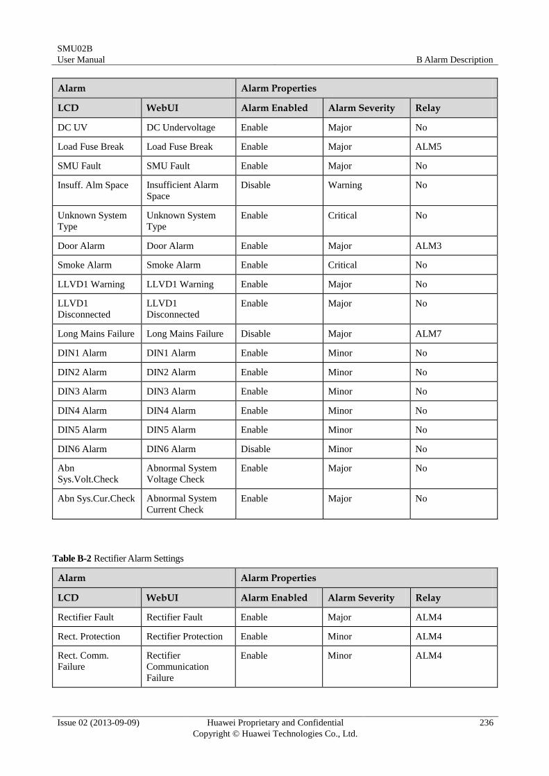
SMU02B
User Manual B Alarm Description
Issue 02 (2013-09-09) Huawei Proprietary and Confidential
Copyright © Huawei Technologies Co., Ltd.
236
Alarm Alarm Properties
LCD WebUI Alarm Enabled Alarm Severity Relay
DC UV DC Undervoltage Enable Major No
Load Fuse Break Load Fuse Break Enable Major ALM5
SMU Fault SMU Fault Enable Major No
Insuff. Alm Space Insufficient Alarm
Space
Disable Warning No
Unknown System
Type
Unknown System
Type
Enable Critical No
Door Alarm Door Alarm Enable Major ALM3
Smoke Alarm Smoke Alarm Enable Critical No
LLVD1 Warning LLVD1 Warning Enable Major No
LLVD1
Disconnected
LLVD1
Disconnected
Enable Major No
Long Mains Failure Long Mains Failure Disable Major ALM7
DIN1 Alarm DIN1 Alarm Enable Minor No
DIN2 Alarm DIN2 Alarm Enable Minor No
DIN3 Alarm DIN3 Alarm Enable Minor No
DIN4 Alarm DIN4 Alarm Enable Minor No
DIN5 Alarm DIN5 Alarm Enable Minor No
DIN6 Alarm DIN6 Alarm Disable Minor No
Abn
Sys.Volt.Check
Abnormal System
Voltage Check
Enable Major No
Abn Sys.Cur.Check Abnormal System
Current Check
Enable Major No
Table B-2 Rectifier Alarm Settings
Alarm Alarm Properties
LCD WebUI Alarm Enabled Alarm Severity Relay
Rectifier Fault Rectifier Fault Enable Major ALM4
Rect. Protection Rectifier Protection Enable Minor ALM4
Rect. Comm.
Failure
Rectifier
Communication
Failure
Enable Minor ALM4
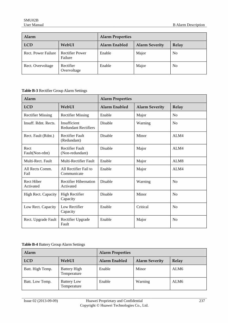
SMU02B
User Manual B Alarm Description
Issue 02 (2013-09-09) Huawei Proprietary and Confidential
Copyright © Huawei Technologies Co., Ltd.
237
Alarm Alarm Properties
LCD WebUI Alarm Enabled Alarm Severity Relay
Rect. Power Failure Rectifier Power
Failure
Enable Major No
Rect. Overvoltage Rectifier
Overvoltage
Enable Major No
Table B-3 Rectifier Group Alarm Settings
Alarm Alarm Properties
LCD WebUI Alarm Enabled Alarm Severity Relay
Rectifier Missing Rectifier Missing Enable Major No
Insuff. Rdnt. Rects. Insufficient
Redundant Rectifiers
Disable Warning No
Rect. Fault (Rdnt.) Rectifier Fault
(Redundant)
Disable Minor ALM4
Rect
Fault(Non-rdnt)
Rectifier Fault
(Non-redundant)
Disable Major ALM4
Multi-Rect. Fault Multi-Rectifier Fault Enable Major ALM8
All Rects Comm.
Fail
All Rectifier Fail to
Communicate
Enable Major ALM4
Rect Hiber
Activated
Rectifier Hibernation
Activated
Disable Warning No
High Rect. Capacity High Rectifier
Capacity Disable Minor No
Low Rect. Capacity Low Rectifier
Capacity
Enable Critical No
Rect. Upgrade Fault Rectifier Upgrade
Fault
Enable Major No
Table B-4 Battery Group Alarm Settings
Alarm Alarm Properties
LCD WebUI Alarm Enabled Alarm Severity Relay
Batt. High Temp. Battery High
Temperature
Enable Minor ALM6
Batt. Low Temp. Battery Low
Temperature Enable Warning ALM6
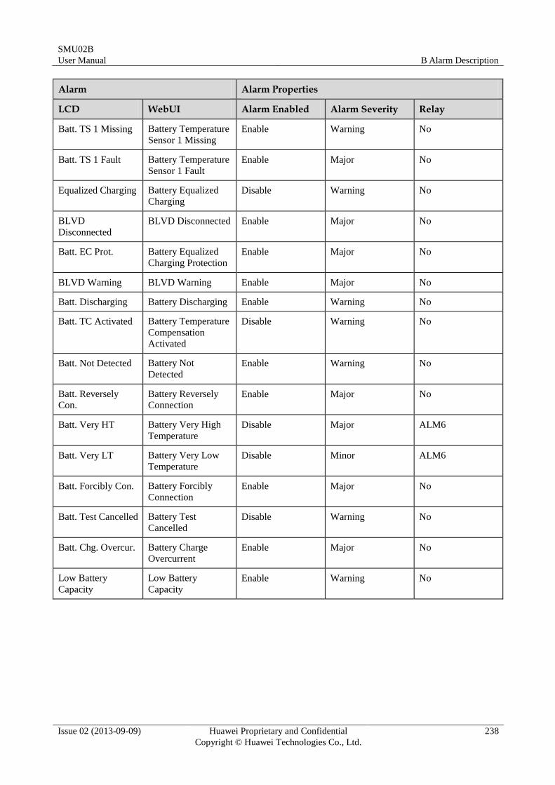
SMU02B
User Manual B Alarm Description
Issue 02 (2013-09-09) Huawei Proprietary and Confidential
Copyright © Huawei Technologies Co., Ltd.
238
Alarm Alarm Properties
LCD WebUI Alarm Enabled Alarm Severity Relay
Batt. TS 1 Missing Battery Temperature
Sensor 1 Missing
Enable Warning No
Batt. TS 1 Fault Battery Temperature
Sensor 1 Fault
Enable Major No
Equalized Charging Battery Equalized
Charging
Disable Warning No
BLVD
Disconnected
BLVD Disconnected Enable Major No
Batt. EC Prot. Battery Equalized
Charging Protection
Enable Major No
BLVD Warning BLVD Warning Enable Major No
Batt. Discharging Battery Discharging Enable Warning No
Batt. TC Activated Battery Temperature
Compensation
Activated
Disable Warning No
Batt. Not Detected Battery Not
Detected
Enable Warning No
Batt. Reversely
Con.
Battery Reversely
Connection Enable Major No
Batt. Very HT Battery Very High
Temperature
Disable Major ALM6
Batt. Very LT Battery Very Low
Temperature
Disable Minor ALM6
Batt. Forcibly Con. Battery Forcibly
Connection
Enable Major No
Batt. Test Cancelled Battery Test
Cancelled
Disable Warning No
Batt. Chg. Overcur. Battery Charge
Overcurrent
Enable Major No
Low Battery
Capacity
Low Battery
Capacity
Enable Warning No
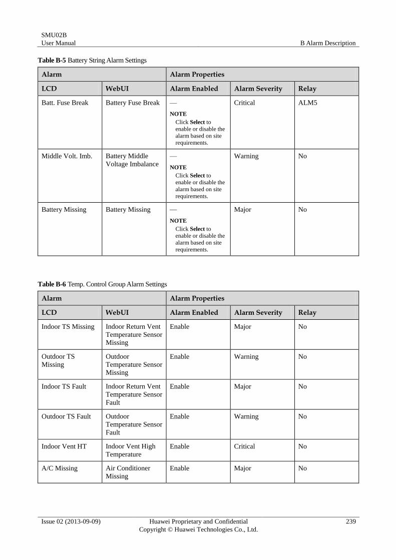
SMU02B
User Manual B Alarm Description
Issue 02 (2013-09-09) Huawei Proprietary and Confidential
Copyright © Huawei Technologies Co., Ltd.
239
Table B-5 Battery String Alarm Settings
Alarm Alarm Properties
LCD WebUI Alarm Enabled Alarm Severity Relay
Batt. Fuse Break Battery Fuse Break —
NOTE
Click Select to
enable or disable the
alarm based on site
requirements.
Critical ALM5
Middle Volt. Imb. Battery Middle
Voltage Imbalance
—
NOTE
Click Select to
enable or disable the
alarm based on site
requirements.
Warning No
Battery Missing Battery Missing —
NOTE
Click Select to
enable or disable the
alarm based on site
requirements.
Major No
Table B-6 Temp. Control Group Alarm Settings
Alarm Alarm Properties
LCD WebUI Alarm Enabled Alarm Severity Relay
Indoor TS Missing Indoor Return Vent
Temperature Sensor
Missing
Enable Major No
Outdoor TS
Missing
Outdoor
Temperature Sensor
Missing
Enable Warning No
Indoor TS Fault Indoor Return Vent
Temperature Sensor
Fault
Enable Major No
Outdoor TS Fault Outdoor
Temperature Sensor
Fault
Enable Warning No
Indoor Vent HT Indoor Vent High
Temperature
Enable Critical No
A/C Missing Air Conditioner
Missing
Enable Major No
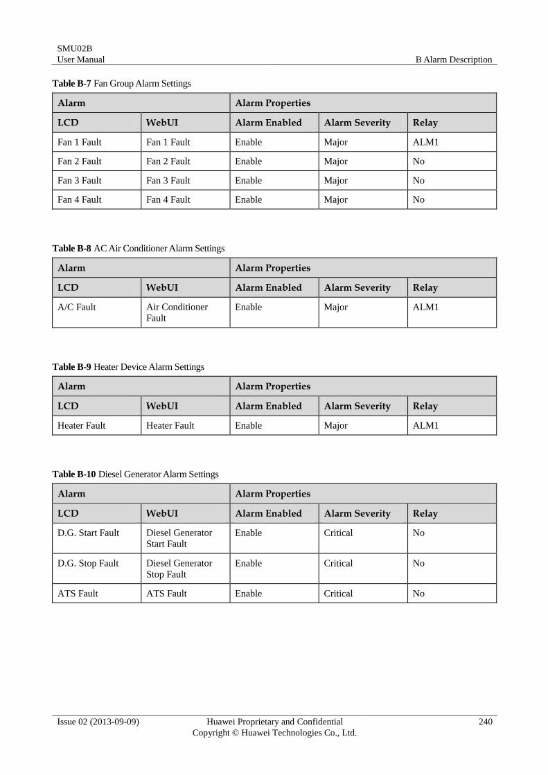
SMU02B
User Manual B Alarm Description
Issue 02 (2013-09-09) Huawei Proprietary and Confidential
Copyright © Huawei Technologies Co., Ltd.
240
Table B-7 Fan Group Alarm Settings
Alarm Alarm Properties
LCD WebUI Alarm Enabled Alarm Severity Relay
Fan 1 Fault Fan 1 Fault Enable Major ALM1
Fan 2 Fault Fan 2 Fault Enable Major No
Fan 3 Fault Fan 3 Fault Enable Major No
Fan 4 Fault Fan 4 Fault Enable Major No
Table B-8 AC Air Conditioner Alarm Settings
Alarm Alarm Properties
LCD WebUI Alarm Enabled Alarm Severity Relay
A/C Fault Air Conditioner
Fault Enable Major ALM1
Table B-9 Heater Device Alarm Settings
Alarm Alarm Properties
LCD WebUI Alarm Enabled Alarm Severity Relay
Heater Fault Heater Fault Enable Major ALM1
Table B-10 Diesel Generator Alarm Settings
Alarm Alarm Properties
LCD WebUI Alarm Enabled Alarm Severity Relay
D.G. Start Fault Diesel Generator
Start Fault
Enable Critical No
D.G. Stop Fault Diesel Generator
Stop Fault
Enable Critical No
ATS Fault ATS Fault Enable Critical No
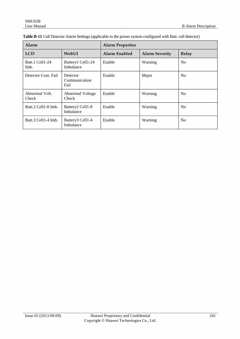
SMU02B
User Manual B Alarm Description
Issue 02 (2013-09-09) Huawei Proprietary and Confidential
Copyright © Huawei Technologies Co., Ltd.
241
Table B-11 Cell Detector Alarm Settings (applicable to the power system configured with Batt. cell detector)
Alarm Alarm Properties
LCD WebUI Alarm Enabled Alarm Severity Relay
Batt.1 Cell1-24
Imb.
Battery1 Cell1-24
Imbalance
Enable Warning No
Detector Com. Fail Detector
Communication
Fail
Enable Major No
Abnormal Volt.
Check
Abnormal Voltage
Check
Enable Warning No
Batt.2 Cell1-8 Imb. Battery2 Cell1-8
Imbalance
Enable Warning No
Batt.3 Cell1-4 Imb. Battery3 Cell1-4
Imbalance
Enable Warning No