smooth particle hydrodynamics birdstrike analysis on
TRANSCRIPT
291 Int. Jnl. of Multiphysics Volume 15 · Number 3 · 2021
Smooth Particle Hydrodynamics Birdstrike Analysis on Aircraft Wing Leading Edge
I Talhah1, P Hampson2* 1. University of Salford, UK
2. Nelson and Colne College Group University Centre, UK
ABSTRACT
Aircraft wing leading edges subjected to simulated birdstrike impact was
investigated using the finite element ANSYS Autodyn solver. The bird was
modelled using a Smooth Particle Hydrodynamics (SPH) method. Two
validation studies were conducted prior to the main investigation. The first
simulated impact on aluminium panels of varying thicknesses and impact
velocities with results compared to Cessna Aircraft Company test data and
a study conducted using LS-Dyna. The second validation study was
performed on a steel plate at various impact velocities with results
compared to U.S. Naval Research Laboratory data and a LS-Dyna solution.
Following the validation studies, bird impact was simulated on aluminium and
carbon fibre composite wing skin leading edges. Various skin thicknesses
were investigated at an impact velocity of 155m/s (300 knots). Leading edge
displacement and stress results showed that the carbon fibre composite
material had a greater resistance than the aluminium to withstanding the
high-speed impact.
1. INTRODUCTION The term ‘birdstrike’ means the collision between a bird and an aircraft front-facing component, e.g., windshields, nacelles, wing leading edges and compressor blades. Bird impact against an aircraft wing may also result in damage to internal systems such as fuel tanks, which can be catastrophic. The probability of an accident is higher during take-off, climb, approach and landing phases since birds are attracted to large, grassed areas such as those surrounding airports. Due to significant increases in air traffic, the birdstrike problem has grown, and more and more aircraft manufactures, and government authorities have initiated research and development programs to ensure that, in according to the International Certification Standards, aircraft are able to withstand the loads due to birdstike impact. Both the Federal Aviation Administration (FAA) [1] and European Aviation Safety Agency (EASA) [2] list regulations for aircraft certification to ensure that front-facing aircraft components should be capable of withstanding birdstrikes at critical flight speeds.
In the 1970’s, various researchers studied birdstrike impacts with several practical design methods in order to define the characteristics of aircraft components that are capable of limiting birdstrike damage. The validation of the bird-proof components was mainly dependent on experiments because of the absence of significant computational tools.
___________________________________ *Corresponding Author: [email protected]
292
Smooth Particle Hydrodynamics Birdstrike Analysis on Aircraft Wing Leading Edge
In 1975, Barber et al. [3] analysed the birdstrike problem by performing experiments of bird impacts against a rigid circular plate. The bird was impacted at different velocities and variations in peak pressure were analysed at different positions on the plate to understand the effect of the impact. Different masses of bird were also employed varying from 60 grams to 4 kilograms at velocities ranging from 50 m/s to 300 m/s. The angle of impact was also investigated in the experiment from normal, to an angle of 25 degrees. The study focused on the peak pressure generated during the impact and found that these were independent of the bird dimensions but proportional to the square of the impact velocity.
In the following year, Barber and Peterson [4] performed a series of birdstrike tests on rigid plates and concluded that the behaviour of the bird can be assimilated to a fluid one and showed that a bird-loading model treated the bird as a fluid dynamic process. The mass of the birds varied from 60 g to 600 g with impact velocities from 100 m/s to 300 m/s at an angle of 90, 45 and 25 degrees. This literature comprised a beneficial amount of information on the impact response of different small birds at varying impact velocities.
In the findings of high velocity bird impact in 1977, Wilbeck [5] also found that the response of the bird was similar to a fluid in which the strength of the material was extremely small compared to the impact loads. Therefore, researchers who experienced difficulties performing experiments with a real bird often substituted a dummy bird made from materials such as foam, wax, gelatin and emulsions. According to Willbeck & Rand [6], gelatin produces a loading profile similar to real birds.
In 1990, Niering [7] studied birdstrike impact computationally and modelled the bird using a Lagrangian approach. This research also presented the need for an optimised numerical technique due to large deformations experienced by the bird in the Lagrangian model. The Arbitrary Lagrangian Eulerian (ALE) method was later used by Stroker [8] in the forming processes. Stroker explained the ALE method through the fundamentals of continuum mechanics, followed by a derivation of the ALE motion description, and a mathematical formulation used for calculations.
Several authors have analysed problems of fluid-structure interaction using the Smooth Particle Hydrodynamics (SPH) approach. In 1999, Nizampatnam [9] analysed birdstrike modelling techniques using the computational methods of Eularian, Langrangian and SPH. Shock pressure decay and steady state pressure parameters were formulated and tabulated according to FAR Parts 23 and 25 during impact simulation. Furthermore, variation of the shape and size of bird model were analysed and different angles of impact were considered during the simulations. The experiments focused on the impact on glass fibre composites and accompanying computational studies concluded that the SPH technique was a practical and feasible method for birdstrike impact simulations.
Further work performed by Lacome [10] provided information regarding the SPH process and approximations for the equations of energy and mass conservation. Other authors also used the SPH approach to model birdstrike phenomenon. Ortecho [11] successfully used this approach to analyse birdstrike impact on rigid plates. The bird impact test was performed at different angles and information such as peak force was tabulated and compared.
293 Int. Jnl. of Multiphysics Volume 15 · Number 3 · 2021
In 2008, Guida [12] studied physical testing of bird impact on aircraft structures. Static tests were performed to determine the stress-strain curve; dynamic tests to evaluate material strain rate sensitivity; and impact tests to determine the threshold for impact energy. Numerical computation times were also discussed for Eularian, Langrangian and SPH techniques using the MSC Dytran solver. Further work by Guida et al. [13] found that the Lagrangian-SPH combination provided the best results in terms of impact visualisation and as a good predictor of projectile deceleration when compared to experimental test results.
In 2010, Walvekar [14] and Walvekar et al. [15] investigated Langrangian and SPH methods using the LS-Dyna solver to solve birdstrike problems. The results of displacement, force, impulse, squash time and rise time were studied and compared with published experimental test data. This study also found the SPH bird model technique to be an efficient method because of minimum computation time. This study presented in this paper provides a methodological approach to the numerical study of birdstrike on an aircraft wing leading edge structure using ANSYS Autodyn finite element solver. The main objectives can be summarised as follows: (1) Design and model a bird using a mesh free, Smooth Particle Hydrodynamics (SPH)
method in ANSYS Autodyn. (2) Validate and compare the SPH bird model in impact simulations on aluminium and steel
targets with published experimental test data and finite element simulations conducted using LS-Dyna.
(3) Model an aircraft wing structure comprising of skin, ribs and spars, and assign materials of aluminium and carbon fibre composite to the wing components.
(4) Analyse the Autodyn SPH bird impact simulation on aluminium and composite wing leading edges of varying skin thicknesses.
2. SPH BIRD MODEL VALIDATION Before studying birdstrike on a full-scale model of an aircraft wing structure as part of this study, two validation exercises were conducted on the bird model. The birdstrike phenomenon was first carried out on a flat aluminium square plate (Section 2.1), and then repeated for a steel plate (Section 2.2). The simulation results were compared with published experimental test data and numerical simulation results.
The bird model used in the simulation was based on a geometry and material type that represents the artificial birds used during physical experiments. Therefore, the bird was modelled as a projectile in the shape of a circular cylinder with properties determined using methodology presented in literature [16].
Subsequently, the model was imported into ANSYS Workbench where an Explicit Dynamics project platform was used to determine the dynamic response of the impact.
Explicit materials of WATER2 was selected from the engineering data library for the bird model, and assigned an initial density of 942.7 kg/m3. The material property of the bird was assumed to be homogenous and isotropic. The model was then meshed in order to create a region of 14154 SPH nodes in ANSYS Autodyn. A link between the Explicit Dynamics project and Autodyn solver was then created in ANSYS Workbench.
294
Smooth Particle Hydrodynamics Birdstrike Analysis on Aircraft Wing Leading Edge
The bird made use of the elastic-plastic hydrodynamics model, where the pressure-volume relationship was governed by an Equation of State (EOS) which behaves as an elastic-plastic material at low pressure. The EOS was defined for the SPH bird model as a composition of 90% water and 10% air. In Autodyn, the bird was defined by an EOS_TABULATED input card as shown in Table 1, where the volumetric strain, 𝜀𝜀𝑣𝑣, and values for function 𝐶𝐶, are substituted to determine the pressure in the bird [17]. Table 1: Equation of State Values [17]
𝜺𝜺𝒗𝒗 𝑪𝑪 (Pa) 0.000 0.000 -0.105 2.37 x 10⁸ -0.118 4.25 x 10⁸ -0.128 5.86 x 10⁸ -0.137 7.27 x 10⁸ -0.154 9.72 x 10⁸ -0.169 1.18 x 10⁹ -0.183 1.37 x 10⁹ -0.195 1.54 x 10⁹ -0.217 1.84 x 10⁹
The equation used for the bird material which calculates the pressure 𝑃𝑃, was defined by:
𝑃𝑃 = 𝐶𝐶(𝜀𝜀𝑉𝑉) + 𝛾𝛾𝛾𝛾(𝜀𝜀𝑉𝑉)𝐸𝐸 (1)
Since the temperature 𝛾𝛾 (dependent on volumetric strain) is considered negligible due to
high-speed impact, the EOS equation can therefore be simplified to:
𝑃𝑃 = 𝐶𝐶(𝜀𝜀𝑉𝑉) (2) 2.1. SPH Bird Impact on Aluminium Target The first numerical validation of the SPH bird model simulated an impact on an Al 7075-T6 aluminium plate which was assigned the following material properties:
𝜌𝜌 = 2804 𝑘𝑘𝑘𝑘/𝑚𝑚3 𝐸𝐸 = 70 𝐺𝐺𝑃𝑃𝐺𝐺 𝜈𝜈 = 0.33 𝜎𝜎𝑌𝑌 = 503 𝑀𝑀𝑃𝑃𝐺𝐺 where, 𝜌𝜌 = density, 𝐸𝐸 = Young’s Modulus, and 𝜈𝜈 = Poisson’s ratio, 𝜎𝜎𝑌𝑌 = Yield strength.
The aluminium plate had dimensions of 914.4 mm in height, and 609.5 mm in width and
was uniformly meshed with Quad elements. The rotational and translational degrees of freedom for the nodes at the edge of the plate were constrained. The SPH bird was positioned at the centre, and normal to the plate with impact velocities of 136, 138 and 141 m/s on plate thicknesses of 6.35, 4.06 and 2.54 mm respectively. The bird model was arranged as close to the target as possible to eliminate unnecessary computer resources (Figure 1).
295 Int. Jnl. of Multiphysics Volume 15 · Number 3 · 2021
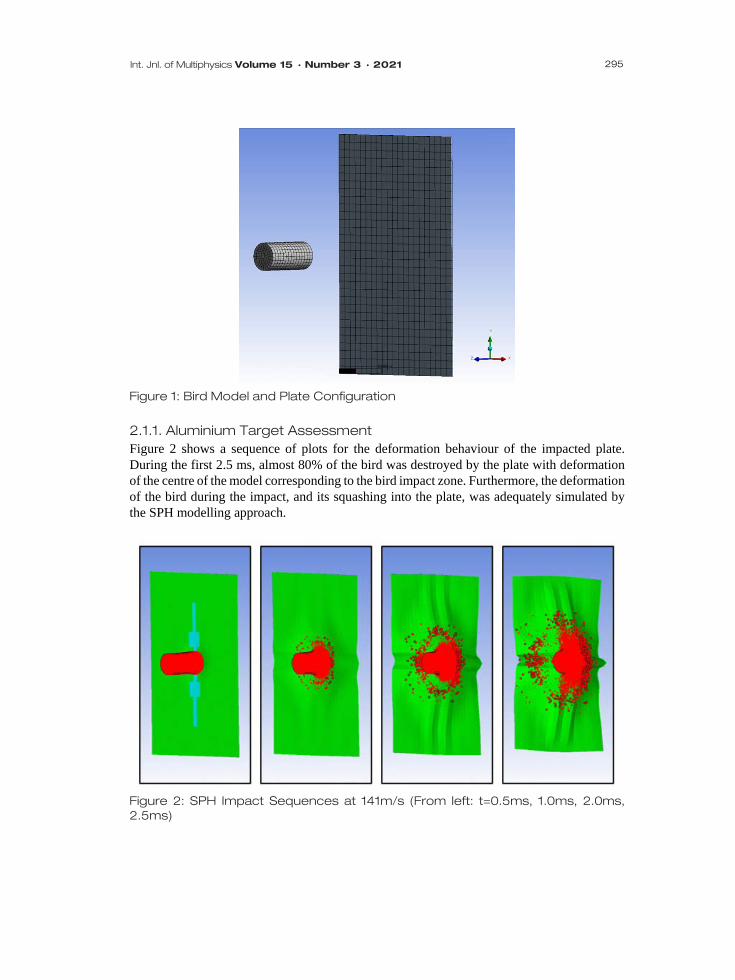
Figure 1: Bird Model and Plate Configuration
2.1.1. Aluminium Target Assessment Figure 2 shows a sequence of plots for the deformation behaviour of the impacted plate. During the first 2.5 ms, almost 80% of the bird was destroyed by the plate with deformation of the centre of the model corresponding to the bird impact zone. Furthermore, the deformation of the bird during the impact, and its squashing into the plate, was adequately simulated by the SPH modelling approach.
Figure 2: SPH Impact Sequences at 141m/s (From left: t=0.5ms, 1.0ms, 2.0ms, 2.5ms)

296
Smooth Particle Hydrodynamics Birdstrike Analysis on Aircraft Wing Leading Edge
The Autodyn SPH results were found to be in reasonable agreement when compared to experimental data obtained from physical tests performed at the Cessna Aircraft Company [18] and numerical analysis results carried out in LS-Dyna using Lagrangian and SPH method [14, 15]. Maximum central plate displacement values for each simulation is shown in Table 2. The Cessna experimental tests were described as using a thawed bird launched towards an aluminium plate where the resulting maximum deflection of the plate was measured using high-speed camera equipment. Table 2: Comparison of Cessna Test Results, LS-Dyna and Autodyn Results Displacement Results (mm) / Material Status Al 7075-T6 Plate Thickness (mm)
Impact Velocity (m/s)
Cessna Test Data Ref. [18]
LS-Dyna Lagrangian Refs. [14, 15]
LS-Dyna SPH Refs. [14, 15]
Autodyn SPH Current Study
6.35 136 25.4 33.02 30.4 31.54 4.06 138 38.1 33.02 45.72 38.95 2.54 141 Failure Failure Failure Failure (67.28) 2.2. SPH Bird Impact on Steel Target The second numerical validation of the SPH bird model was to simulate an impact on a steel plate which was assigned the following material properties:
𝜌𝜌 = 7850 𝑘𝑘𝑘𝑘/𝑚𝑚3 𝐸𝐸 = 193 𝐺𝐺𝑃𝑃𝐺𝐺 𝜈𝜈 = 0.3 𝜎𝜎𝑌𝑌 = 250 𝑀𝑀𝑃𝑃𝐺𝐺 where, 𝜌𝜌 = density, 𝐸𝐸 = Young’s Modulus, and 𝜈𝜈 = Poisson’s ratio, 𝜎𝜎𝑌𝑌 = Yield strength.
The steel plate had a height, width and thickness of 914.4, 609.5, and 9.52 mm respectively,
and was constrained along the edges in X, Y, and Z directions. The bird was impacted at an angle normal to the target plate with impact velocities of 192,
219, 249 and 269 m/s. The bird model geometry was cylindrical and had a diameter of 0.098 m and length 0.188 m (note: hemispherical ends were not modelled). 2.2.1. Steel Target Assessment The Autodyn simulation results were then compared to experiments conducted by the U.S. Naval Research Laboratory [19] and LS-Dyna SPH simulations [14, 15]. The results were converted to non-dimensional values for comparison with the reference data for peak force, impulse transfer, impact duration and rise time.
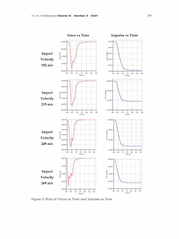
Figure 3 shows the Autodyn impact simulation results of force verses time, and impulse verses time graphs for the four different impact velocities considered.
297 Int. Jnl. of Multiphysics Volume 15 · Number 3 · 2021
Figure 3: Plots of ‘Force vs Time’ and ‘Impulse vs Time
298
Smooth Particle Hydrodynamics Birdstrike Analysis on Aircraft Wing Leading Edge
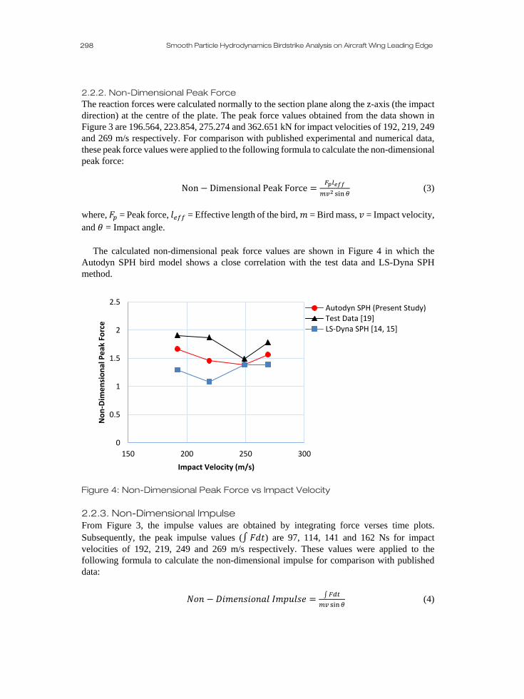
2.2.2. Non-Dimensional Peak Force The reaction forces were calculated normally to the section plane along the z-axis (the impact direction) at the centre of the plate. The peak force values obtained from the data shown in Figure 3 are 196.564, 223.854, 275.274 and 362.651 kN for impact velocities of 192, 219, 249 and 269 m/s respectively. For comparison with published experimental and numerical data, these peak force values were applied to the following formula to calculate the non-dimensional peak force:
Non − Dimensional Peak Force =𝐹𝐹𝑝𝑝𝑙𝑙𝑒𝑒𝑒𝑒𝑒𝑒
𝑚𝑚𝑣𝑣2 sin𝜃𝜃 (3)
where, 𝐹𝐹𝑝𝑝 = Peak force, 𝑙𝑙𝑒𝑒𝑒𝑒𝑒𝑒 = Effective length of the bird, 𝑚𝑚 = Bird mass, 𝑣𝑣 = Impact velocity, and 𝜃𝜃 = Impact angle.
The calculated non-dimensional peak force values are shown in Figure 4 in which the
Autodyn SPH bird model shows a close correlation with the test data and LS-Dyna SPH method.
Figure 4: Non-Dimensional Peak Force vs Impact Velocity 2.2.3. Non-Dimensional Impulse From Figure 3, the impulse values are obtained by integrating force verses time plots. Subsequently, the peak impulse values (∫ 𝐹𝐹𝐹𝐹𝐹𝐹) are 97, 114, 141 and 162 Ns for impact velocities of 192, 219, 249 and 269 m/s respectively. These values were applied to the following formula to calculate the non-dimensional impulse for comparison with published data:
𝑁𝑁𝑁𝑁𝑁𝑁 − 𝐷𝐷𝐷𝐷𝑚𝑚𝐷𝐷𝑁𝑁𝐷𝐷𝐷𝐷𝑁𝑁𝑁𝑁𝐺𝐺𝑙𝑙 𝐼𝐼𝑚𝑚𝐼𝐼𝐼𝐼𝑙𝑙𝐷𝐷𝐷𝐷 = ∫𝐹𝐹𝐹𝐹𝐹𝐹𝑚𝑚𝑣𝑣 sin𝜃𝜃
(4)
0
0.5
1
1.5
2
2.5
150 200 250 300
Non
-Dim
ensi
onal
Pea
k Fo
rce
Impact Velocity (m/s)
Autodyn SPH (Present Study)Test Data [19]LS-Dyna SPH [14, 15]
299 Int. Jnl. of Multiphysics Volume 15 · Number 3 · 2021
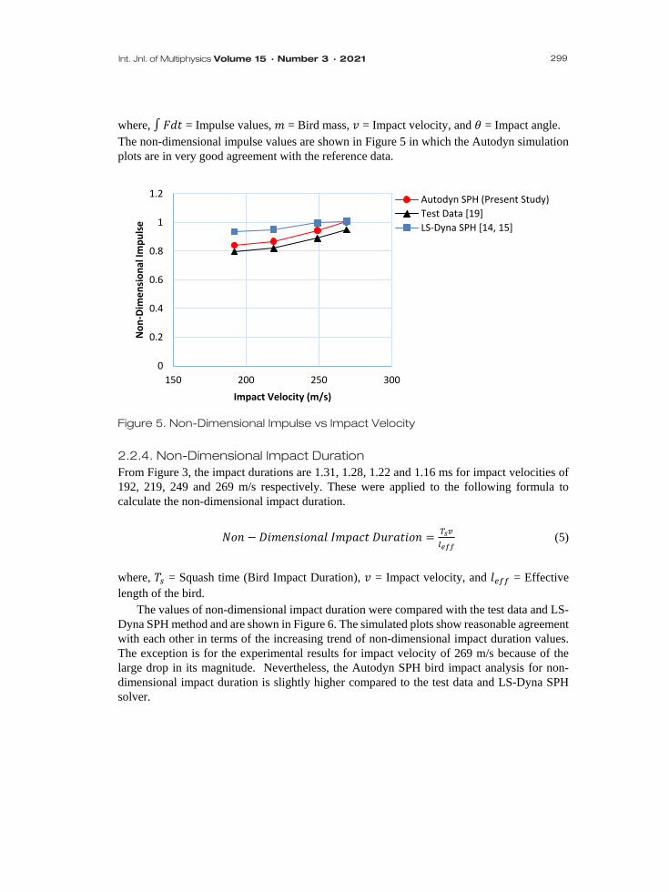
where, ∫ 𝐹𝐹𝐹𝐹𝐹𝐹 = Impulse values, 𝑚𝑚 = Bird mass, 𝑣𝑣 = Impact velocity, and 𝜃𝜃 = Impact angle. The non-dimensional impulse values are shown in Figure 5 in which the Autodyn simulation plots are in very good agreement with the reference data.
Figure 5. Non-Dimensional Impulse vs Impact Velocity
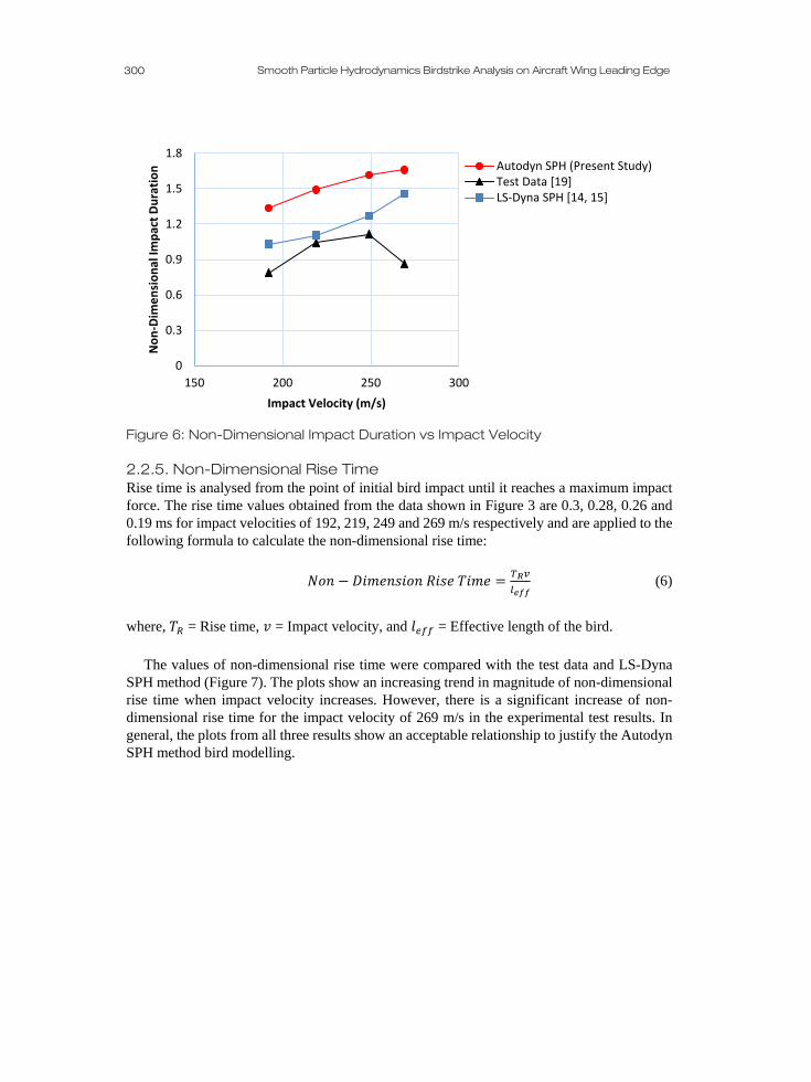
2.2.4. Non-Dimensional Impact Duration From Figure 3, the impact durations are 1.31, 1.28, 1.22 and 1.16 ms for impact velocities of 192, 219, 249 and 269 m/s respectively. These were applied to the following formula to calculate the non-dimensional impact duration.
𝑁𝑁𝑁𝑁𝑁𝑁 − 𝐷𝐷𝐷𝐷𝑚𝑚𝐷𝐷𝑁𝑁𝐷𝐷𝐷𝐷𝑁𝑁𝑁𝑁𝐺𝐺𝑙𝑙 𝐼𝐼𝑚𝑚𝐼𝐼𝐺𝐺𝐼𝐼𝐹𝐹 𝐷𝐷𝐼𝐼𝐷𝐷𝐺𝐺𝐹𝐹𝐷𝐷𝑁𝑁𝑁𝑁 = 𝑇𝑇𝑠𝑠𝑣𝑣𝑙𝑙𝑒𝑒𝑒𝑒𝑒𝑒
(5)
where, 𝛾𝛾𝑠𝑠 = Squash time (Bird Impact Duration), 𝑣𝑣 = Impact velocity, and 𝑙𝑙𝑒𝑒𝑒𝑒𝑒𝑒 = Effective length of the bird.
The values of non-dimensional impact duration were compared with the test data and LS-Dyna SPH method and are shown in Figure 6. The simulated plots show reasonable agreement with each other in terms of the increasing trend of non-dimensional impact duration values. The exception is for the experimental results for impact velocity of 269 m/s because of the large drop in its magnitude. Nevertheless, the Autodyn SPH bird impact analysis for non-dimensional impact duration is slightly higher compared to the test data and LS-Dyna SPH solver.
0
0.2
0.4
0.6
0.8
1
1.2
150 200 250 300
Non
-Dim
ensi
onal
Impu
lse
Impact Velocity (m/s)
Autodyn SPH (Present Study)Test Data [19]LS-Dyna SPH [14, 15]
300
Smooth Particle Hydrodynamics Birdstrike Analysis on Aircraft Wing Leading Edge
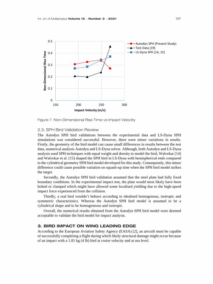
Figure 6: Non-Dimensional Impact Duration vs Impact Velocity 2.2.5. Non-Dimensional Rise Time Rise time is analysed from the point of initial bird impact until it reaches a maximum impact force. The rise time values obtained from the data shown in Figure 3 are 0.3, 0.28, 0.26 and 0.19 ms for impact velocities of 192, 219, 249 and 269 m/s respectively and are applied to the following formula to calculate the non-dimensional rise time:
𝑁𝑁𝑁𝑁𝑁𝑁 − 𝐷𝐷𝐷𝐷𝑚𝑚𝐷𝐷𝑁𝑁𝐷𝐷𝐷𝐷𝑁𝑁𝑁𝑁 𝑅𝑅𝐷𝐷𝐷𝐷𝐷𝐷 𝛾𝛾𝐷𝐷𝑚𝑚𝐷𝐷 = 𝑇𝑇𝑅𝑅𝑣𝑣𝑙𝑙𝑒𝑒𝑒𝑒𝑒𝑒
(6)
where, 𝛾𝛾𝑅𝑅 = Rise time, 𝑣𝑣 = Impact velocity, and 𝑙𝑙𝑒𝑒𝑒𝑒𝑒𝑒 = Effective length of the bird.
The values of non-dimensional rise time were compared with the test data and LS-Dyna
SPH method (Figure 7). The plots show an increasing trend in magnitude of non-dimensional rise time when impact velocity increases. However, there is a significant increase of non-dimensional rise time for the impact velocity of 269 m/s in the experimental test results. In general, the plots from all three results show an acceptable relationship to justify the Autodyn SPH method bird modelling.
0
0.3
0.6
0.9
1.2
1.5
1.8
150 200 250 300
Non
-Dim
ensi
onal
Impa
ct D
urat
ion
Impact Velocity (m/s)
Autodyn SPH (Present Study)Test Data [19]LS-Dyna SPH [14, 15]
301 Int. Jnl. of Multiphysics Volume 15 · Number 3 · 2021
Figure 7. Non-Dimensional Rise Time vs Impact Velocity
2.3. SPH Bird Validation Review The Autodyn SPH bird validations between the experimental data and LS-Dyna SPH simulations was considered successful. However, there were minor variations in results. Firstly, the geometry of the bird model can cause small differences in results between the test data, numerical analysis Autodyn and LS-Dyna solver. Although, both Autodyn and LS-Dyna analysis used SPH techniques with equal weight and density to model the bird, Walvekar [14] and Walvekar et al. [15] shaped the SPH bird in LS-Dyna with hemispherical ends compared to the cylindrical geometry SPH bird model developed for this study. Consequently, this minor difference could cause possible variation on squash-up time when the SPH bird model strikes the target.
Secondly, the Autodyn SPH bird validation assumed that the steel plate had fully fixed boundary conditions. In the experimental impact test, the plate would most likely have been bolted or clamped which might have allowed some localised yielding due to the high-speed impact force experienced from the collision.
Thirdly, a real bird wouldn’t behave according to idealised homogenous, isotropic and symmetric characteristics. Whereas the Autodyn SPH bird model is assumed to be a cylindrical shape and to be homogeneous and isotropic.
Overall, the numerical results obtained from the Autodyn SPH bird model were deemed acceptable to validate the bird model for impact analysis. 3. BIRD IMPACT ON WING LEADING EDGE According to the European Aviation Safety Agency (EASA) [2], an aircraft must be capable of successfully completing a flight during which likely structural damage might occur because of an impact with a 1.81 kg (4 lb) bird at cruise velocity and at sea level.
0
0.1
0.2
0.3
0.4
0.5
150 200 250 300
Non
-Dim
ensi
onal
Ris
e Ti
me
Impact Velocity (m/s)
Autodyn SPH (Present Study)Test Data [19]LS-Dyna SPH [14, 15]
302
Smooth Particle Hydrodynamics Birdstrike Analysis on Aircraft Wing Leading Edge
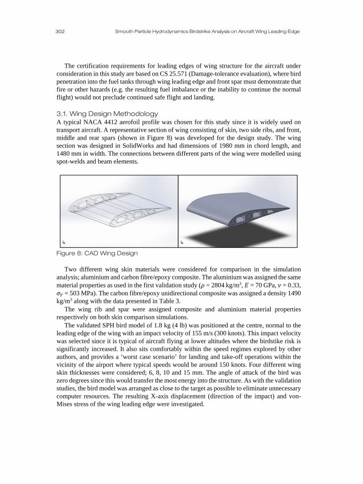
The certification requirements for leading edges of wing structure for the aircraft under consideration in this study are based on CS 25.571 (Damage-tolerance evaluation), where bird penetration into the fuel tanks through wing leading edge and front spar must demonstrate that fire or other hazards (e.g. the resulting fuel imbalance or the inability to continue the normal flight) would not preclude continued safe flight and landing. 3.1. Wing Design Methodology A typical NACA 4412 aerofoil profile was chosen for this study since it is widely used on transport aircraft. A representative section of wing consisting of skin, two side ribs, and front, middle and rear spars (shown in Figure 8) was developed for the design study. The wing section was designed in SolidWorks and had dimensions of 1980 mm in chord length, and 1480 mm in width. The connections between different parts of the wing were modelled using spot-welds and beam elements.
Figure 8: CAD Wing Design
Two different wing skin materials were considered for comparison in the simulation analysis; aluminium and carbon fibre/epoxy composite. The aluminium was assigned the same material properties as used in the first validation study (𝜌𝜌 = 2804 kg/m3, 𝐸𝐸 = 70 GPa, 𝜈𝜈 = 0.33, 𝜎𝜎𝑌𝑌 = 503 MPa). The carbon fibre/epoxy unidirectional composite was assigned a density 1490 kg/m3 along with the data presented in Table 3.
The wing rib and spar were assigned composite and aluminium material properties respectively on both skin comparison simulations.
The validated SPH bird model of 1.8 kg (4 lb) was positioned at the centre, normal to the leading edge of the wing with an impact velocity of 155 m/s (300 knots). This impact velocity was selected since it is typical of aircraft flying at lower altitudes where the birdstike risk is significantly increased. It also sits comfortably within the speed regimes explored by other authors, and provides a ‘worst case scenario’ for landing and take-off operations within the vicinity of the airport where typical speeds would be around 150 knots. Four different wing skin thicknesses were considered; 6, 8, 10 and 15 mm. The angle of attack of the bird was zero degrees since this would transfer the most energy into the structure. As with the validation studies, the bird model was arranged as close to the target as possible to eliminate unnecessary computer resources. The resulting X-axis displacement (direction of the impact) and von-Mises stress of the wing leading edge were investigated.

303 Int. Jnl. of Multiphysics Volume 15 · Number 3 · 2021
Table 3: Carbon Fibre/Epoxy Unidirectional Composite Material Properties
Property Stress Values (Pa) Strain Values Tensile X 2.231 x 10⁹ 0.0167 Tensile Y 2.90 x 10⁷ 0.0032 Tensile Z 2.90 x 10⁷ 0.0032
Compressive X -1.082 x 10⁹ -0.0108 Compressive Y -1.00 x 10⁸ -0.0192 Compressive Z -1.00 x 10⁸ -0.0192
Shear XY 6.00 x 10⁷ 0.012 Shear YZ 3.20 x 10⁷ 0.11 Shear XZ 6.00 x 10⁷ 0.012
3.2. Bird Impact on Aluminium Wing Figure 9 shows the SPH bird impact sequence with a velocity of 155 m/s on an elastic-plastic aluminium wing leading edge of 6 mm skin thickness.
Figure 9. Time Lapse of SPH Birdstrike on Aluminium Wing Leading Edge
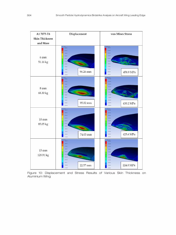
The maximum displacement and von-Mises stress results for the four various skin thicknesses are shown in Figure 10.
The displacement results shown in Figure 10 show an increase when the skin thickness decreases. In addition, post-impact analysis showed that the leading edge deformed considerably towards the front spar for aluminium skin thicknesses of 6 mm, 8 mm and 10 mm. However, further assessment of the front spar component on each wing configuration showed no significant damage.
In the aluminium properties stated earlier, Al 7075-T6 has a yield stress of 503 MPa. Figure 10 shows von-Mises stress results of 458.9, 430.2, 425.6 and 224.0 MPa on wing skin thicknesses of 6, 8, 10 and 15 mm respectively. Although the thinnest wing skin did come close to the yield stress limit, all simulations resulted in maximum von-Mises stress values below the yield stress.
304
Smooth Particle Hydrodynamics Birdstrike Analysis on Aircraft Wing Leading Edge
Figure 10: Displacement and Stress Results of Various Skin Thickness on Aluminium Wing

305 Int. Jnl. of Multiphysics Volume 15 · Number 3 · 2021
3.3. Bird Impact on Composite Wing Figure 11 shows the SPH bird impact sequence with a velocity of 155 m/s on a composite wing leading edge of 6mm skin thickness.
Figure 11: Time Lapse of SPH Birdstrike on Composite Wing Leading Edge
The maximum displacement and von-Mises stress results for various skin thicknesses are shown in Figure 12.
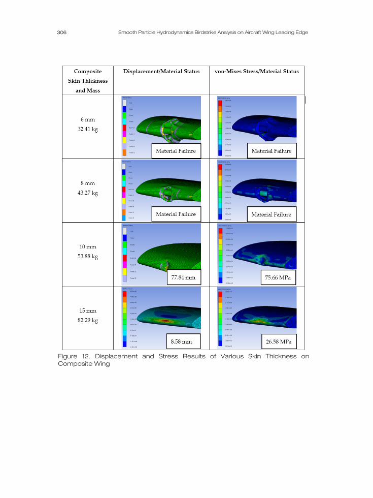
As seen in Figure 12, the bird impact simulation ruptures the composite wing leading edge for skin thicknesses of 6mm and 8mm. This type of damage could lead to penetration of fuel tanks and other important components in the wing structure. For wing skin thicknesses of 10 mm and 15 mm, the numerical analysis showed leading edge displacements of 77.84 mm and 8.58 mm respectively. For these last two thicknesses, even though the composite laminates had suffered delamination on several plies, the wing leading edge stayed intact as a whole. Most of the kinetic energy of the bird was absorbed by the delamination of the carbon fibre sheets which prevented the penetration of the composite skin. As a result, this would suggest the capability of continued safe flight and landing of the aircraft after impact.
306
Smooth Particle Hydrodynamics Birdstrike Analysis on Aircraft Wing Leading Edge
Figure 12. Displacement and Stress Results of Various Skin Thickness on Composite Wing
307 Int. Jnl. of Multiphysics Volume 15 · Number 3 · 2021
4. CONCLUSION The aim of this study was to examine the impact response of an aircraft wing leading edge structure that satisfies regulatory birdstrike requirements. The bird was modelled using a mesh free Smooth Particle Hydrodynamics technique to predict the impact damage of the wing structure with ANSYS Autodyn. The internal pressure of the bird model was linked to the change in volume with an Equation of State.
The Autodyn SPH bird model was validated by carrying out comparison with published experimental data and finite element solutions conducted using LS-Dyna. The first validation was compared to the data obtained from physical tests carried out by the Cessna Aircraft Company [18] and numerical results of LS-Dyna Langrangian and SPH methods [14, 15]. The second validation was compared with test data conducted by the U.S. Naval Research Laboratory [19] and numerical results from LS-Dyna SPH analysis [14, 15]. For both validation studies, the predicted Autodyn results were found to be in good agreement.
Subsequently, the validated SPH bird model was impacted on aluminium and composite wing leading edges with various skin thicknesses of 6, 8, 10 and 15 mm at an impact velocity of 155 m/s (300 knots). Autodyn SPH results of the leading-edge displacement and von-Mises stress were evaluated and showed that the material integrity of 15 mm composite wing thickness was notably better when compared to the aluminium wing. From the impact results seen in Figure 10 and Figure 12, the lowest wing leading edge displacement values were for the 15 mm wing skin thickness; the aluminium wing displacement was 22.57 mm and the composite wing was 8.58 mm. Also, for the von-Mises stress results for the 15 mm skin thickness, the aluminium wing was 224 MPa and the composite wing was 26.58 MPa.
Furthermore, the composite material had an excellent strength to weight ratio, since the 15mm composite wing skin had a mass approximately 37% less than the comparable aluminium wing. These weight savings can lead to increases in aircraft payload such as cargo, passengers or fuel. Nonetheless, composites are more brittle and more vulnerable to impact than aluminium designs. The post-impact physical condition of the 6 mm and 8 mm skin thickness for the composite wing showed that the bird model penetrated the skin and completely perforated the leading edge compared to large deformation and non-penetration of the aluminium wing with similar skin thicknesses.
It is noted that whilst composite materials have been used by many manufacturers to construct wing leading edges, the general preference in the latest generation of aircraft is to employ metal alloys (with composite material retained for the upper and lower wing skins). This is mainly due to two reasons, firstly, the metal alloys tend to display greater resistance to complete failure (e.g. as demonstrated within this study where only the composite material experienced complete material rupture). Secondly, the reparability of metal alloy structures is significantly easier than composite materials which is particularly important for forward facing components that are more likely to encounter damage.
308
Smooth Particle Hydrodynamics Birdstrike Analysis on Aircraft Wing Leading Edge
REFERENCES [1] FAA Code of Federal Regulations. Title 14 – Aeronautics and Space. Federal Aviation
Administration, Department of Transportation USA, 2017. Available online: https://www.ecfr.gov/cgi-bin/text-idx?SID=df49bda166bae1cd31a4abe789bdeea3&mc=true&tpl=/ecfrbrowse/Title14/14cfrv1_02.tpl (accessed on 20 July 2020).
[2] EASA. Certification Specifications for Large Aeroplanes CS-25. Cologne, Germany, 2007.
[3] Barber, J.P., Taylor, H.R. and Wilbeck, J.S. Characterization of Bird Impacts on a Rigid Plate: Part 1. Research Institute - University of Dayton, Ohio, 1975. Available online: https://apps.dtic mil/dtic/tr/fulltext/u2/a021142.pdf (accessed on 20 July 2020).
[4] Barber, J.P. and Peterson, R.L. Bird Impact Forces in Aircraft Windshield Design. Research Institute - University of Dayton, Ohio, 1976.
[5] Wilbeck, J.S. Impact Behavior of Low Strength Projectiles. PhD Thesis, Texas A&M University, 1977.
[6] Wilbeck, J.S. and Rand, J.L. The Development of a Substitute Bird Model. Journal of Engineering for Power, 1981. 103(4): p. 725-730. DOI: https://doi.org/10.1115/1.3230795
[7] Niering, E. Simulation of Bird Strikes on Turbine Engines. Journal of Engineering for Gas Turbines and Power, 1990. 112(4): p 573-578. DOI: https://doi.org/10.1115/1.2906207
[8] Stroker, C. Developments of the Arbitrary Lagrangian-Eulerian Method in Non-Linear Solid Mechanics Applications to Forming Processes. PhD Thesis, University of Twente, Enschedel, 1999.
[9] Nizampatnam, L. Models and Methods for Bird Strike Load Predictions. PhD Thesis, Wichita State University, Kansas, 1999.
[10] Lacome, J.L. Smooth Particle Hydrodynamics (SPH): A new feature in LS-Dyna. In 6th International LS-Dyna Users Conference, Detroit, USA, 2000. Available online: http://www.dynalook.com/international-conf-2000/session7-3.pdf (accessed on 01 August 2020).
[11] Ortecho, C.A.H. Robust Birdstrike Modelling using LS-Dyna. MSc Thesis, University of Puerto Rico, Puerto Rico, 2006.
[12] Guida, M. Study, Design, and Testing of Structural Configurations for the Bird Strike Compliance of Aeronautical Components. PhD Thesis, University of Naples, Italy, 2008.
[13] Guida, M., Marulo, F., Meo, M., Grimaldi, A. and Olivares, G. SPH – Lagrangian Study of Bird Impact on Leading Edge Wing. Composite Structures, 2011. 93(3), p. 1060-1071.
[14] Walvekar, V. Birdstrike Analysis using a Smooth Particle Hydrodynamics Bird Model in LS-Dyna. MSc Thesis, Wichita State University, Wichita, 2010. Available online: https://soar.wichita.edu/bitstream/handle/10057/3339/t10048_Walvekar.pdf (accessed on 21 July 2020).

309 Int. Jnl. of Multiphysics Volume 15 · Number 3 · 2021
[15] Walvekar, V.; Thorbole, C.K.; Bhonge, P.; Lankarani, H.M. Birdstrike Analysis on Leading Edge of an Aircraft Wing Using a Smooth Particle Hydrodynamics Bird Model. Proceedings of the ASME 2010 International Mechanical Engineering Congress & Exposition, IMECE2010, Vancouver, British Columbia, Canada, 12-18 November 2010. ISBN: 978-0-7918-4425-0.
[16] Australian Transport Safety Bureau. The Hazard Posed to Aircraft by Birds. Department of Transport and Regional Services, Australia, 2002. p. 42-44. Available online: https://www.atsb.gov.au/media/43383/Hazard_aircraft_by_birds.pdf (accessed on 01 August 2020).
[17] Grimaldi, A. SPH High Velocity Impact Analysis. A Birdstrike Windshield Application. PhD Thesis, University of Naples Federico II, Italy, 2011. Available online: http://www.fedoa.unina.it/8221/1/grimaldi_arcangelo_23.pdf (accessed on 03 August 2020).
[18] Furtado, R.D. Finite Element Analysis of Birdstrike on Aircraft Structures. Department of Mechanical Engineering, Wichita State University, 2000.
[19] U.S. Navy. The Shock and Vibration Bulletin. A Publication of Shock and Vibration Information Centre. U.S. Naval Research Laboratory, Washington D.C., 1978.

310