smfrwf: segmented modified fractional wavelet filter: fast
TRANSCRIPT

Received May 13, 2019, accepted June 19, 2019, date of publication June 24, 2019, date of current version July 12, 2019.
Digital Object Identifier 10.1109/ACCESS.2019.2924490
SMFrWF: Segmented Modified Fractional WaveletFilter: Fast Low-Memory Discrete WaveletTransform (DWT)MOHD TAUSIF 1, (Student Member, IEEE), EKRAM KHAN1, (Senior Member, IEEE),MOHD HASAN1, (Senior Member, IEEE), AND MARTIN REISSLEIN 2, (Fellow, IEEE)1Department of Electronics Engineering, Aligarh Muslim University, Aligarh 202002, India2Goldwater Center, School of Electrical, Computer, and Energy Engineering, Arizona State University, Tempe, AZ 85287-5706, USA
Corresponding author: Martin Reisslein ([email protected])
The work of M. Tausif was supported by the Ministry of Electronics and Information Technology, Government of India, through theVisvesvaraya Ph.D. Scheme.
ABSTRACT This paper proposes a novel algorithm to compute the 2-D discrete wavelet transform (DWT)of high-resolution (HR) images on low-cost visual sensor and Internet of Things (IoT) nodes. The mainadvantages of the proposed segmented modified fractional wavelet filter (SMFrWF) are reduced compu-tation (time) complexity and energy consumption compared to the state-of-the-art low-memory 2-D DWTcomputation methods. In particular, the conventional convolution-based DWT is very fast but requires largerandom access memory (RAM), as the entire image needs to be in the systemmemory. The fractional waveletfilter (FrWF) requires only a small RAM but has high complexity due to multiple readings of image lines.The proposed SMFrWF avoids the multiple readings of image lines, thus reducing the memory read accesstime and, thereby, the complexity. We evaluated the proposed SMFrWF through MATLAB simulations with70 popular gray-scale test images of dimensions ranging from 256×256 up to 8192×8192 pixels. The resultsshow that for images of size 2048 × 2048 pixels, the proposed SMFrWF (with four segments per line) has16.8% and 53.6% lower time complexities than the conventional DWT and FrWF, respectively. The proposedSMFrWF has also been modeled in a hardware description language (HDL) and implemented on an Artix-7 field-programmable gate array (FPGA) platform to evaluate the hardware performance. We observed thatthe proposed SMFrWF has 65% lower energy consumption than the FrWF (both implemented on the sameboard). Thus, the proposed SMFrWF appears suitable for computing the wavelet transform coefficients ofHR images on low-cost visual sensors and IoT platforms.
INDEX TERMS Discrete wavelet transform (DWT), low memory, low complexity, low-cost portabledevices, visual sensors.
I. INTRODUCTIONA. MOTIVATIONHigh-resolution (HR) images generally incorporate moredetails of a scene or phenomenon than low-resolution images;hence, HR images are used in many applications, such assatellite imaging, medical imaging, and intelligent surveil-lance [1]–[5]. HR images are preferred for medical diag-nosis due to their higher information content, which maybe critical in many situations. The performance of patternrecognition systems can be enhanced through HR images [6].
The associate editor coordinating the review of this manuscript andapproving it for publication was Tie Qiu.
Remote sensing and LANDSAT applications [7]–[9] captureimages of geographical areas, whereby object recognitionis easier in HR satellite images [10]. Due to the increasingdemand for HR images, there is a need to develop efficientcoders for HR images on low-cost visual sensors.
Most existing image coding algorithms are either based onthe Discrete Cosine Transform (DCT) or the DiscreteWaveletTransform (DWT). Due to its excellent decorrelation, energycompaction, and symmetry properties, the DCT has beenwidely adopted in image and video coding standards, suchas JPEG, MPEG-2, H.264, and HEVC [11]. The DCT isgenerally applied on image blocks, thereby reducing therequired memory, but coding block-based DCT coefficients
84448 This work is licensed under a Creative Commons Attribution 3.0 License. For more information, see http://creativecommons.org/licenses/by/3.0/ VOLUME 7, 2019
M. Tausif et al.: SMFrWF: Fast Low-Memory DWT
at very low bit-rates leads to blocking artifacts. Furthermore,the block-based DCT only exploits the correlations within theblocks, limiting the coding efficiency. In contrast, the DWTis applied on the entire image; thus, DWT based coders canachieve higher coding efficiency than DCT based coders [12].Recently, the DWT has become very popular in image codingapplications, including the JPEG 2000 coder, real-time pro-cessing, and biomedical signal processing [11].
The conventional DWT computation method requires thecomplete image to be kept in memory which is challengingfor memory-constrained devices, such as digital cameras,personal digital assistants (PDAs) [13] and wireless video-phones [14]. These low-cost mass-market consumer deviceshave only limited memory [12]. Moreover, there are manyimaging oriented applications, such as visual sensors (sensornodes with a small camera), with very limited on-board mem-ory. A network of visual sensors, called visual sensor network(VSN) or wireless multimedia sensor network (WMSN), hasseveral applications, such as visual surveillance of wild ani-mals, automatic road traffic monitoring, and mobile multi-media [15]. The sensor nodes can capture both multimediaand non-multimedia data [16]. These nodes can also be usedin IoT applications, such as smart home monitoring, smartcities, and smart health care systems [17]–[19]. However,the sensor nodes have limited RAM memory and power.For example, the available memory on many low-cost sensornodes is only of the order of 10 kB [20]. The conventionalDWT computation method requires 524 kB of RAM fora gray-scale image of size 256 × 256 pixels [21] and thememory requirement increases linearly with the image size.Hence, the conventional DWT computation method cannotbe implemented in memory-constrained environments. Var-ious low-memory methods to compute the DWT have beendeveloped, such as the line-based DWT [12], the block-basedDWT [22], the stripe-based DWT [23], and the FractionalWavelet Filter (FrWF) [21]. The FrWF is the most memoryefficient, requiring only 2.304 kB, 4.608 kB, and 9.216 kBmemory for images of size 256 × 256, 512 × 512, and1024× 1024 pixels, respectively [20].
Although the FrWF has a low memory requirement, itsmemory requirement increases with the image size and there-fore for HR images (images of size larger than 1024×1024),the FrWF memory requirement may exceed the memoryavailable on typical sensor nodes (which is of the orderof 10 kB). Furthermore, the FrWF achieves the low memoryrequirement at the expense of increased time and computa-tional complexity, as it requires 3.25 times more multiplica-tion operations and 2.89 times more addition operations thanthe conventional DWT [21]. Low-cost hand-held multimediadevices and visual sensors are constrained in terms of mem-ory and computational capabilities as well as battery power.Therefore, from the complexity point of view, the FrWFmay not be suitable for these devices. Hence, there is aneed to develop a technique that can compute the DWT withlow memory as well as lower computational complexity thanthe existing techniques.
For image transmission over bandwidth-limited commu-nication channels, e.g., in wireless networks, the transformcoefficients computed by the DWT need to be com-pressed (coded) using an efficient image coding algorithm.Assuming that the two operational stages (transform andcoding) are performed serially, the overall memory require-ment of the image coder is the maximum of the memoryrequirements of the two stages and the overall time com-plexity of the coder is the sum of the complexities of theindividual stages. Among the various wavelet-based imagecoding algorithms, the Zero Memory Set Partitioned Embed-ded Block Coder (ZM-SPECK) [24], the LowMemory BlockTree Coder (LMBTC) [25], and the Wavelet Image twoline coder (Wi2l) [26] satisfy the memory constraint of low-cost visual sensor nodes. Among these, ZM-SPECK [24]requires the least memory and is theoretically a memory-lesscoder. ZM-SPECK does not require any memory for itsimplementation (except for a few buffers and storage forvariables), yet it needs to be combined with a suitable trans-form to design an image coder. Thus, the transform memorydetermines the overall codec memory; therefore, the trans-form memory needs to be reduced to design a low-cost imagecoder.
B. RELATED WORKThe first effort to reduce the memory for the one-dimensional(1-D) DWT was made in [27]. The various popularlow-memory 2-D DWT techniques fall into three cate-gories: line-based approaches [12], [13], [28], block-basedapproaches [22], [29]–[31], and stripe-based approaches [23],[32]–[36]. For the line-based DWT, only the rows necessaryfor computing the DWT are kept in RAM. The line-basedapproach implemented using the lifting scheme in [13] isfaster than the conventional DWT approach but requires12 image lines to be stored in RAM [21].
Architectures based on line based scanning techniqueshave been proposed in [37]–[41]. The architectures reportedin [37], [38] require memory greater than 5.5N , for an N ×N dimension image, whereas the design of [39] uses 9 Nstorage cells. The architecture proposed in [40] needs a con-stant transposition memory of 4 words only, but requires atemporal memory of 5.5N . The architecture proposed in [41]has reduced the temporal memory to 3 N and needs fewerhardware resources; however, it still requires a transpositionmemory of size N . Further reduction in hardware resourcescan be achieved at the cost of a higher number of computationcycles.
Block-based approaches apply the wavelet transform onimage blocks, rather than on the complete image. Gen-erally, the line-based and block-based DWT computationapproaches require the same amount of memory [20]. DWTarchitectures for block-based scanning have been proposedin [42]–[44]. The architecture presented in [42] has highthroughput at the expense of large temporal and transpo-sition memories and extensive arithmetic resources. Thedesign proposed in [43] requires large memory (of the order
VOLUME 7, 2019 84449

M. Tausif et al.: SMFrWF: Fast Low-Memory DWT
of N 2+ 4N words as reported in [45]). Moreover, the
design of [43] mainly emphasizes speed (fast computation)and does not appropriately consider the energy and area con-straints [46]. The architecture proposed in [44] reduces theinternal memory size, but increases the external bandwidthand computation time.
The stripe-based DWT is equivalent to the line-based DWTapplied on wider ‘‘line’’ of blocks. The memory requirementof all these stripe-based approaches for a typical 512 × 512gray-scale image is about 26 kB [20], which is more thanthe available RAM of many low-cost visual sensor nodes.Architectures for computing the DWT based on stripe-basedscanningmethods have been proposed in [47]–[49]. Althoughthe architecture proposed in [47] needs no temporal memory,it requires a large line buffer and a complex control scheme.The architecture proposed in [49] has been developed forcomputing 1-D transform coefficients only. The modifiedstripe-based architecture presented in [50] has a long compu-tation time. Furthermore, the memory requirements of otherstate-of-the-art DWT architectures, such as [51], [52] aremore than the RAM available on most of the low-cost sensornodes.
The lifting scheme [53] is another popular method forcomputing the DWT. The lifting scheme uses in-place com-putations, which interleave low frequency and high frequencytransform coefficients to reduce the required memory. Forthe line-based DWT computation, the lifting scheme needs tostore only 12 image lines; whereas, without lifting, 18 imagelines need to be stored [21]. In order to compensate for thisinterleaving, the coefficients need to be reordered, whichincreases the complexity [13]. The execution time requiredby the lifting scheme is almost the same as that of the con-ventional DWT [13].
Overall, the lowest transform memory to date has beenachieved by the line-based FrWF [20], [21]. However, eventhe FrWF is not suitable for transforming high-resolution(HR) images on low-cost memory-constrained plat-forms [54], as the available memory is less than that requiredfor HR images. In order to further reduce the FrWF memoryrequirement, a Segmented FrWF (SFrWF) has been pro-posed [54]. The SFrWF partitions an image line into differentsegments and then applies the FrWF to these segments. TheSFrWF needs less memory than the FrWF, but has highcomplexity. Therefore from the complexity point of view,the SFrWF is not suitable for low-cost visual sensor nodes.
C. CONTRIBUTION OF THIS PAPERIn this paper, we propose a novel technique to compute theDWT of images with much lower time complexity than theSFrWF. The proposed technique enables the implementa-tion of HR image coding on low-cost resource-constraineddevices, such as VSNs and IoT platforms.
The proposed Modified FrWF (MFrWF) uses the conven-tional DWT for computing the horizontal 1-D DWT. How-ever, for subsequent column-wise filtering, a novel approachis proposed in which a line is read only once, and the line
is filtered partially and values are stored and subsequentlyupdated. The novelty of the proposed MFrWF is that thecolumn-wise filtering is performed in such a way that aline needs to be accessed only once and required multiplica-tions with corresponding filter coefficients are performed andresults are stored in buffers. The difference between the FrWFand the proposed MFrWF is that the FrWF reads an imageline multiple times because an image line is part of multiplevertical filter areas as explained in Sections II-B and III-A.The MFrWF avoids the multiple readings of an image lineby using three different processes with intermediate buffers,as explained in detail in Section III-B. Experimental resultsdemonstrate that the proposed MFrWF significantly reducesthe time complexity (typically to a half or a third) comparedto the FrWF.
Due to the additional storage of intermediate values,the MFrWF memory requirement is slightly increased com-pared to the FrWF. The MFrWF memory requirement can bereduced by the proposed SMFrWF, which partitions an imageline into multiple segments. Only one segment is read at atime into RAM and the subband coefficients of the segmentare computed using the MFrWF procedure. The SMFrWFrequires somewhat larger memory than the correspondingSFrWF, but the SMFrWF does enable the transformation ofHR images of size 4096 × 4096 pixels on nodes with 10 kBof RAM. The SMFrWF time complexity for such HR imagetransformations is less than half of the corresponding SFrWFtime complexity. To the best of our knowledge, the proposedSMFrWF is the first attempt to develop an alternative tothe FrWF that reduces the computation complexity for HRimage wavelet transforms on low-memory portable multime-dia devices.
The rest of the paper is organized as follows. Section IIgives brief overviews of the conventional DWT and FrWF.Section III introduces the proposed MFrWF and SMFrWFalong with the pseudo-code as well as memory and com-plexity analyses. Section IV presents evaluation results formemory, time complexity, and quality of the reconstructedimage, as well as a hardware implementation. Section Vconcludes the paper and outlines future research directions.
II. BACKGROUNDIn this section, we briefly review the conventional DWT andFrWF schemes for computing the wavelet transform coeffi-cients of an image. Throughout, we assume, as is commonin low-memory image transform and coding studies, that theoriginal image and its transformed coefficients are stored inan external secure digital (SD) card. Data is read from theSD card into the system’s limited RAMmemory as and whenneeded.
A. OVERVIEW OF CONVENTIONAL 2-D DWTThe conventional 2-D DWT approach first filters (convolves)all the rows of an image by a low pass filter (LPF) and a highpass filter (HPF), followed by downsampling by a factor oftwo, resulting in two subbands, namely the approximation
84450 VOLUME 7, 2019
M. Tausif et al.: SMFrWF: Fast Low-Memory DWT
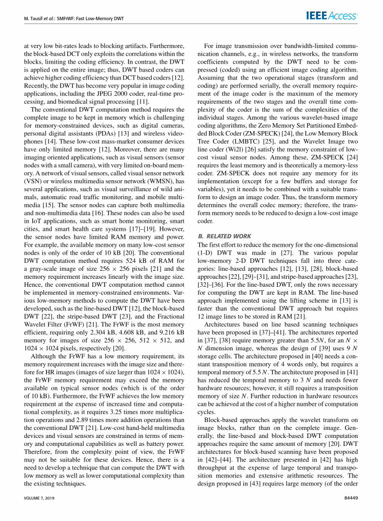
TABLE 1. Summary of main notations.
subband L, and the detail subband H . The process is thenrepeated on all the columns of subbands L and H , resultingin the LL, LH , HL, and HH subbands. The downsamplingcombined with the convolution operations with the LPF andHPF (for symmetric filters) can be expressed as [20]:
L(i) =j=b nl2 c∑j=−b nl2 c
x2i+jlj i = 0, 1, . . . ,N2− 1 (1)
H (i) =j=b nh2 c∑j=−b nh2 c
x2i+j+1hj i = 0, 1, . . . ,N2− 1, (2)
where lj and hj denote coefficient j of the LPF and HPF,respectively, x2i+j denotes the (2i+ j)th sample of the signal,and nl and nh are the lengths of the LPF andHPF, respectively.Table 1 summarizes the main notations used in this article.The symbol bxc denotes the largest integer less than or equalto x. L(i) and H (i) are the ith coefficient of subbands L andH , respectively. The LPF center is aligned with the odd signalvalues, i.e., x0, x2, . . . , xN
2 −2, and the HPF center is aligned
with the even signal values, i.e., x1, x3, · · · ·, xN2 −1
. Borderdiscontinuities are avoided by symmetrically extending b nl2 csamples on both sides. If the original image is of dimensionN × N , the resulting subbands LL, LH , HL, and HH are ofdimension N
2 ×N2 each. For a gray-scale image (8 bits per
pixel) of dimension N × N , the conventional DWT compu-tation method requires the entire image to be kept in RAM.Thememory requirement is 4N 2 bytes for floating point filtervalues, see Appendix A.
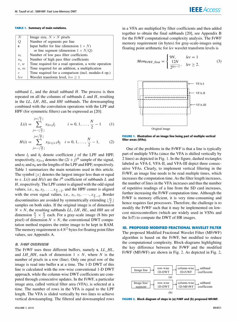
B. FrWF OVERVIEWThe FrWF uses three different buffers, namely s, LL_HL,and LH_HH , each of dimension 1 × N , where N is thenumber of pixels in a row (line). Only one pixel row of theimage is read into buffer s at a time. The 1-D DWT of thisline is calculated with the row-wise conventional 1-D DWTapproach, while the column-wise DWT coefficients are com-puted through consecutive updates. In the FrWF, a particularimage area, called vertical filter area (VFA), is selected at atime. The number of rows in the VFA is equal to the LPFlength. The VFA is slided vertically by two lines to achievevertical downsampling. The filtered and downsampled rows
in a VFA are multiplied by filter coefficients and then addedtogether to obtain the final subbands [20], see Appendix Bfor the FrWF computational complexity analysis. The FrWFmemory requirement (in bytes) for gray-scale-images usingfloating point arithmetic for lev wavelet transform levels is
MemFrWF_float =
9N , lev = 112N2lev−1
, lev ≥ 2.(3)
FIGURE 1. Illustration of an image line being part of multiple verticalfilter areas (VFAs).
One of the problems in the FrWF is that a line is typicallypart of multiple VFAs (since the VFA is shifted vertically by2 lines) as depicted in Fig. 1. In the figure, dashed rectangleslabeled as VFA-I, VFA-II, and VFA-III depict three consec-utive VFAs. Clearly, to implement vertical filtering in theFrWF, an image line needs to be read multiple times, whichincreases the computation time. As the filter length increases,the number of lines in the VFA increases and thus the numberof repetitive readings of a line from the SD card increases,further increasing the FrWF computation time. Although theFrWF is memory efficient, it is very time-consuming andhence requires fast processors. Therefore, the challenge is tomodify the FrWF such that it may be implemented on low-cost microcontrollers (which are widely used in VSNs andthe IoT) to compute the DWT of HR images.
III. PROPOSED MODIFIED FRACTIONAL WAVELET FILTERThe proposed Modified Fractional Wavelet Filter (MFrWF)algorithm is based on the FrWF, but modified to reducethe computational complexity. Block-diagrams highlightingthe key difference between the FrWF and the modifiedFrWF (MFrWF) are shown in Fig. 2. As depicted in Fig. 2,
FIGURE 2. Block diagram of steps in (a) FrWF and (b) proposed MFrWF.
VOLUME 7, 2019 84451

M. Tausif et al.: SMFrWF: Fast Low-Memory DWT
FIGURE 3. Position of filter coefficients for computing LL and HH subbands in different VFAs for 5/3 filterbank.
the difference lies in the way the column-wise filtering is per-formed. The proposed MFrWF avoids multiple readings of aline belonging to different VFAs while computing the verticalfiltering, thereby reducing the computation time. This processrequires some additional memory, which can be compensatedfor by applying the algorithm on segmented lines, rather thanon the whole line. This section presents the details of theMFrWF method as well as its memory requirements andcomplexity characteristics.
A. PROBLEM FORMULATIONIn order to facilitate the understanding of the proposedMFrWF method, it is helpful to analyze the problems in thecolumn-wise filtering in the FrWF in detail. Let us assumethat an image (of size N × N ) has already undergone therow-wise (horizontal) low-pass and high-pass filtering using5/3 filter banks, resulting in the L and H subbands (eachof size N
2 × N ), respectively, as depicted in Fig. 3. (Otherfilters can be accommodated in analogous fashion.) In Fig. 3,Li and Hi represent row i of the L and H subbands, respec-tively. The rows with index i < 0 or i > N are thesymmetrically extended rows beyond the image boundaries.To apply column-wise (vertical) low-pass and high-pass fil-tering, the columns of subbands L and H (within a VFA)need to be convolved with the impulse responses of thecorresponding filters. The black dots in Fig. 3 represent thepositions of the central LPF and HPF coefficient (l0 and h0),respectively. In the FrWF, only one line is read at a time andall its elements are multiplied by the filter coefficients shown(for subbands LL andHH only) adjacent to the correspondingrows in Fig. 3 and the results are stored in buffers. The processis repeated for each rowwithin a VFA and the previous resultsare subsequently updated. The completion of this process fora VFA results in one row of each of the LL, LH , HL, and HHsubbands. The VFA is then shifted by two lines, to achievevertical downsampling by a factor of two.
As is evident from Fig. 3, for computing the LL subbandcoefficients, all elements of odd indexed rows of the L sub-band (except L1) are multiplied by l−2, l0, and l2; whereas,all elements of even indexed rows of the L subband are mul-tiplied by l1 and l−1. Likewise, the HH subband coefficientsare obtained by multiplying the elements of the H subbandeither with h0 (for even indexed rows) or with h1 and h−1(for odd indexed rows), as shown in Fig. 3. Similarly, the LHand HL subband coefficients are computed by multiplyingthe rows of subbands L and H with the HPF and LPF coef-ficients, respectively. The mathematical justifications of thisFrWF process is given in Appendix B. In order to implementthe vertical filtering in FrWF, a row is read as many timesas the number of different filter coefficients it has to bemultiplied with. Furthermore, since each VFA is processedindependently, a line (row) is read at least once in each VFA.However, since a row may be part of more than one VFA,the FrWF requires multiple readings of lines. Thus, the FrWFconsumes a lot of computation time due to multiple readingsof lines (which increase the memory read/access time) whileimplementing vertical filtering. Reducing the computationtime due to multiple readings of lines during vertical filteringis the main contribution of this paper.
B. MODIFIED FrWF (MFrWF)1) MFrWF OVERVIEWIn order to reduce the FrWF complexity, we modify theprocess of column-wise filtering in the FrWF so as to obtainthe proposed MFrWF. Fig. 4 shows the schematic diagram ofthe proposed MFrWF. The MFrWF implementation requireseight buffers (for a 5/3 filter): an input buffer s of dimension1×N (to store a line of an image of sizeN×N ); a buffer bL/Hof dimension 1 × N
2 (to store the coefficients of subbands Lor H ), and six intermediate buffers, namely b1_ll , b2_ll , blh,b1_hl , b2_hl and bhh; each of dimension 1× N
2 (to store newly
84452 VOLUME 7, 2019

M. Tausif et al.: SMFrWF: Fast Low-Memory DWT
FIGURE 4. Schematic diagram illustrating the modified FrWF (MFrWF) technique for a 5/3 filter.
TABLE 2. Filter coefficients and buffers to be used in different processes to compute DWT using 5/3 filter. The ∗ symbol indicates that after thecorresponding subband coefficients have been computed and saved in the external SD card, the buffer is reset.
generated or updated intermediate coefficients of subbandsLL, LH , HL, and HH ).
The MFrWF algorithm works as follows. It reads one row(say row i) of the image at a time into buffer s. Dependingon the row index i, it calls one of three processes, namelyProcess 1 (P1), Process 2 (P2), or Process 3 (P3), to performthe 2-D filtering. For even indexed rows, Process 1 (P1) iscalled; whereas, for odd-indexed rows, the process is selectedas follows: If the value of j = i mod 4 (result of modulo-4operation on line index i) is 1, then Process 2 (P2) is selected;on the other hand, if the value of j = i mod 4 is 3, thenProcess 3 (P3) is selected. Processes 2 and 3 compute theeven and odd rows of the subbands, respectively, as shownin Fig. 4.
2) MFrWF P1, P2, AND P3 PROCESSESEach of the three processes consists of two stages. In the firststage (equivalent to horizontal filtering), the row stored inbuffer s is low/high-pass filtered (conventional convolution)
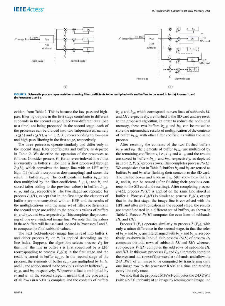
and the values, after down-sampling by 2, are stored in bufferbL/H . In the second stage (equivalent to the vertical filtering),the contents of buffer bL/H are multiplied with low/high-passfilter coefficients and stored (after update, if required) in thecorresponding intermediate buffers, as shown in Fig. 5(a) forProcess 1 and Fig. 5(b) for Processes 2 and 3. In this figure,f1, f2, f3, f4, and f5 are filter coefficients, while b1, b2, b3, b4,and b5 are buffers. The filter coefficients and the buffers to beused in the different processes are listed in Table 2.We note that in the first stage, input lines are first low-
pass filtered and sent to the second stage through bufferbL/H . After completing the second stage, the input line frombuffer s is high-pass filtered in the first stage and processedin the second stage. In this way, a single buffer bL/H isused to store the output of both low and high-pass filtersin the first stage. Furthermore, the filter coefficients usedfor the multiplications in the second stage in a process remainthe same, irrespective of the type of filtering in the firststage; however, the intermediate buffers used are different as
VOLUME 7, 2019 84453
M. Tausif et al.: SMFrWF: Fast Low-Memory DWT
FIGURE 5. Schematic process representation showing filter coefficients to be multiplied with and buffers to be saved in for (a) Process 1, and(b) Processes 2 and 3.
evident from Table 2. This is because the low-pass and high-pass filtering outputs in the first stage contribute to differentsubbands in the second stage. Since two different data (oneat a time) are being processed in the second stage, each ofthe processes can be divided into two subprocesses, namely{Pq(L) and Pq(H ), q = 1, 2, 3}, corresponding to low-passand high-pass filtering in the first stage, respectively.
The three processes operate similarly and differ only inthe second stage filter coefficients and buffers, as depictedin Table 2. We describe the operation of the processes asfollows. Consider process P1 for an even-indexed line i thatis currently in buffer s: The line is first processed throughP1(L), which convolves the image line with an LPF usingEqn. (1) (which incorporates downsampling) and stores theresult in buffer bL/H . The coefficients in buffer bL/H arethen multiplied by the filter coefficients l−1, l1, and h0 andstored (after adding to the previous values) in buffers b1_ll ,b2_ll , and blh, respectively. The two stages are repeated forprocess P1(H ), except that in the first stage the elements ofbuffer s are now convolved with an HPF, and the results ofthe multiplications with the same set of filter coefficients inthe second stage are added to the previous values of buffersb1_hl , b2_hl , and bhh, respectively. This completes the process-ing of one even-indexed image line. We note that the valuesin these buffers will be used and updated in Processes 2 and 3,to compute the final subband values.
The next (odd-indexed) image line is read into buffer s,and either process P2 or P3 is applied depending on theline index. Suppose, the algorithm selects process P2 forthis line: the line in buffer s is first convolved by a LPF(corresponding to process P2(L)) in the first stage and theresult is stored in buffer bL/H . In the second stage of theprocess, the elements of buffer bL/H are multiplied by l0, l2,and h1 and added/stored to the previous values in buffers b1_ll ,b2_ll , and blh, respectively. Whenever a line is multiplied byl2 and h1 in the second stage, it means that the processingof all rows in a VFA is complete and the contents of buffers
b2_ll and blh, which correspond to even lines of subbands LLand LH , respectively, are flushed to the SD card and are reset.In the proposed algorithm, in order to reduce the additionalmemory, these two buffers b2_ll and blh can be reused tostore the intermediate results of multiplication of the contentsof buffer bL/H with other filter coefficients within the sameprocess.
After resetting the contents of the two flushed buffersb2_ll and blh, the elements of buffer bL/H are multiplied bythe remaining coefficients, i.e., l−2 and h−1, and the resultsare stored in buffers b2_ll and blh, respectively, as depictedin Table 2,P2(L) process rows. This completes processP2(L).We emphasize that in Table 2, buffers b2 and b3 are reused asbuffers b4 and b5 after flushing their contents to the SD card.The dashed boxes and lines in Fig. 5(b) show how buffersb2 and b3 can be reused (after flushing their previous con-tents to the SD card and resetting). After completing processP2(L), process P2(H ) is applied on the same line stored inbuffer s. Process P2(H ) is similar to process P2(L), exceptthat in the first stage, the image line is convolved with theHPF and after multiplication in the second stage, the resultsare stored/updated in a different set of buffers, as shown inTable 2. Process P2(H ) computes the even lines of subbandsHL and HH .
Process 3 (P3) operates similarly to process 2 (P2), withonly a minor difference in the second stage, in that the rolesof b1_ll and b1_hl are interchangedwith b2_ll and b2_hl , respec-tively, as shown in Table 2. Sub-process P3(L) of process P3computes the odd rows of subbands LL and LH ; whereas,sub-process P3(H ) computes the odd rows of subbands HLandHH . In this way, processesP2 andP3 alternately computethe even and odd rows of four wavelet subbands, and allow the2-D DWT of an image to be computed by transferring onlyone image row to the processor RAM at a time and readingevery line only once.
We note that the proposedMFrWF computes the 2-DDWT(with a 5/3 filter bank) of an image by reading each image line
84454 VOLUME 7, 2019
M. Tausif et al.: SMFrWF: Fast Low-Memory DWT
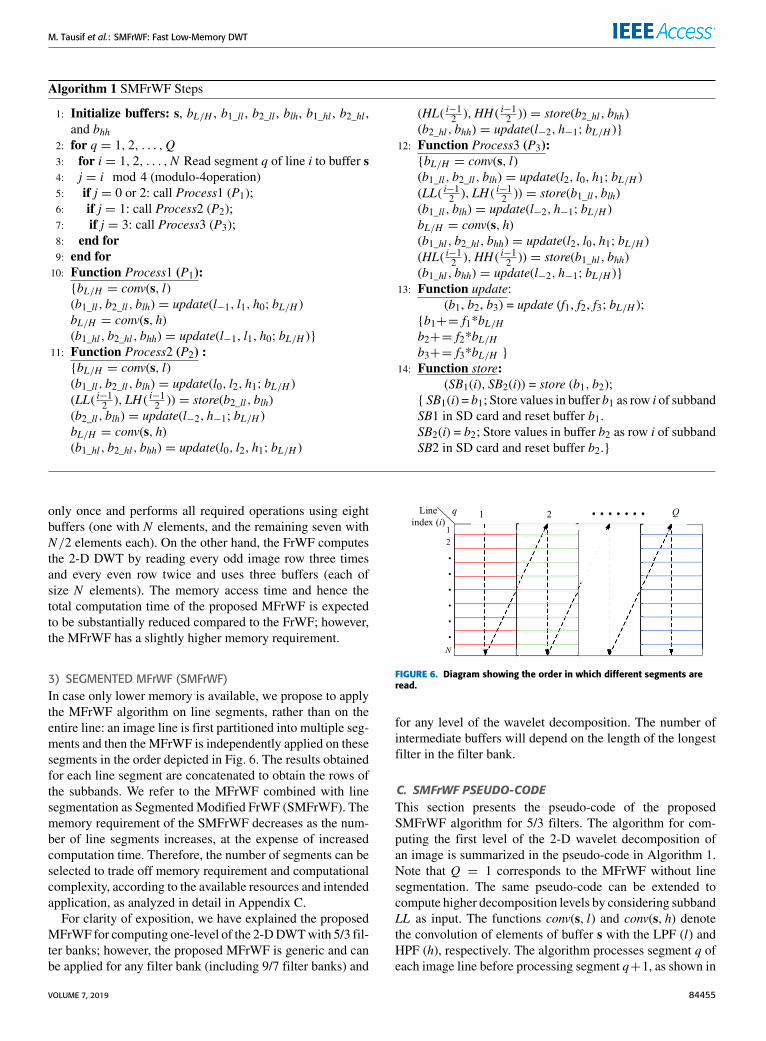
Algorithm 1 SMFrWF Steps
1: Initialize buffers: s, bL/H , b1_ll , b2_ll , blh, b1_hl , b2_hl ,and bhh
2: for q = 1, 2, . . . ,Q3: for i = 1, 2, . . . ,N Read segment q of line i to buffer s4: j = i mod 4 (modulo-4operation)5: if j = 0 or 2: call Process1 (P1);6: if j = 1: call Process2 (P2);7: if j = 3: call Process3 (P3);8: end for9: end for
10: Function Process1 (P1):{bL/H = conv(s, l)(b1_ll, b2_ll, blh) = update(l−1, l1, h0; bL/H )bL/H = conv(s, h)(b1_hl, b2_hl, bhh) = update(l−1, l1, h0; bL/H )}
11: Function Process2 (P2) :{bL/H = conv(s, l)(b1_ll, b2_ll, blh) = update(l0, l2, h1; bL/H )(LL( i−12 ),LH ( i−12 )) = store(b2_ll, blh)(b2_ll, blh) = update(l−2, h−1; bL/H )bL/H = conv(s, h)(b1_hl, b2_hl, bhh) = update(l0, l2, h1; bL/H )
(HL( i−12 ),HH ( i−12 )) = store(b2_hl, bhh)(b2_hl, bhh) = update(l−2, h−1; bL/H )}
12: Function Process3 (P3):{bL/H = conv(s, l)(b1_ll, b2_ll, blh) = update(l2, l0, h1; bL/H )(LL( i−12 ),LH ( i−12 )) = store(b1_ll, blh)(b1_ll, blh) = update(l−2, h−1; bL/H )bL/H = conv(s, h)(b1_hl, b2_hl, bhh) = update(l2, l0, h1; bL/H )(HL( i−12 ),HH ( i−12 )) = store(b1_hl, bhh)(b1_hl, bhh) = update(l−2, h−1; bL/H )}
13: Function update:(b1, b2, b3) = update (f1, f2, f3; bL/H );
{b1+= f1*bL/Hb2+= f2*bL/Hb3+= f3*bL/H }
14: Function store:(SB1(i), SB2(i)) = store (b1, b2);
{ SB1(i) = b1; Store values in buffer b1 as row i of subbandSB1 in SD card and reset buffer b1.SB2(i) = b2; Store values in buffer b2 as row i of subbandSB2 in SD card and reset buffer b2.}
only once and performs all required operations using eightbuffers (one with N elements, and the remaining seven withN/2 elements each). On the other hand, the FrWF computesthe 2-D DWT by reading every odd image row three timesand every even row twice and uses three buffers (each ofsize N elements). The memory access time and hence thetotal computation time of the proposed MFrWF is expectedto be substantially reduced compared to the FrWF; however,the MFrWF has a slightly higher memory requirement.
3) SEGMENTED MFrWF (SMFrWF)In case only lower memory is available, we propose to applythe MFrWF algorithm on line segments, rather than on theentire line: an image line is first partitioned into multiple seg-ments and then the MFrWF is independently applied on thesesegments in the order depicted in Fig. 6. The results obtainedfor each line segment are concatenated to obtain the rows ofthe subbands. We refer to the MFrWF combined with linesegmentation as Segmented Modified FrWF (SMFrWF). Thememory requirement of the SMFrWF decreases as the num-ber of line segments increases, at the expense of increasedcomputation time. Therefore, the number of segments can beselected to trade off memory requirement and computationalcomplexity, according to the available resources and intendedapplication, as analyzed in detail in Appendix C.
For clarity of exposition, we have explained the proposedMFrWF for computing one-level of the 2-DDWTwith 5/3 fil-ter banks; however, the proposed MFrWF is generic and canbe applied for any filter bank (including 9/7 filter banks) and
FIGURE 6. Diagram showing the order in which different segments areread.
for any level of the wavelet decomposition. The number ofintermediate buffers will depend on the length of the longestfilter in the filter bank.
C. SMFrWF PSEUDO-CODEThis section presents the pseudo-code of the proposedSMFrWF algorithm for 5/3 filters. The algorithm for com-puting the first level of the 2-D wavelet decomposition ofan image is summarized in the pseudo-code in Algorithm 1.Note that Q = 1 corresponds to the MFrWF without linesegmentation. The same pseudo-code can be extended tocompute higher decomposition levels by considering subbandLL as input. The functions conv(s, l) and conv(s, h) denotethe convolution of elements of buffer s with the LPF (l) andHPF (h), respectively. The algorithm processes segment q ofeach image line before processing segment q+1, as shown in
VOLUME 7, 2019 84455

M. Tausif et al.: SMFrWF: Fast Low-Memory DWT
Fig. 6. The vertical scanning of segments reduces the size ofeach buffer by a factor of Q (the number of segments in eachline).
D. MFrWF COMPUTATIONAL COMPLEXITYThis section summarizes the evaluation (for details seeAppendix D) of the time required to compute the 2-D DWTwith the proposed MFrWF (with and without line segmenta-tion) and compares with the conventional DWT, FrWF, andsegmented FrWF (SFrWF). The total time consumed (CTotal)for computing the 2-D DWT is the sum of the time consumedfor accessing (read/write) the SD card data (CSD_Access) andthe time required to perform arithmetic operations (CArithm).The SD card access timeCSD_Access depends on the number
of read and write operations, whereas the computation timeCArithm depends on the number of additions, multiplications,and comparisons. The time required for memory access in theMFrWF is:
CSD_Access_MFrWF = N 2r + N 2w, (4)
where r and w denote the time required to read and write onepixel, respectively. The numbers of read and write operationsrequired for computing the 2-DDWT of images using variousmethods are listed in Table 3. We note from Table 3 thatthe number of write operations of the conventional DWTis 2N 2 (as explained in Appendix A), whereas the othermethods need only N 2 write operations. The numbers of readoperations in the proposed MFrWF and SMFrWF are lessthan in the conventional DWT, FrWF, and SFrWF. In fact,the numbers of read operations in the FrWF and SFrWFare the highest among the considered DWT computationapproaches. The numbers of read operations in the MFrWFand SMFrWF are less than in the conventional DWT, despitethe fact that the number of read operations in the SMFrWFincreases with increasing Q (see Appendix E).
As detailed in Appendix D, the MFrWF computationtime is
CArithm_MFrWF = N 2 [2(nl − 2)a+ nlm]+ Nc, (5)
where a, m, and c denote the time required to perform oneaddition, one multiplication, and one comparison (includingthe modulo-4), respectively, and nl is the LPF length. TheN comparisons (one for each image line) are required todecide which process is to be performed on the current line.From Eqns. (4) and (5) for the MFrWF in comparison to thetime complexities in Table 3 for the conventional DWT andFrWF, we observe that the MFrWF substantially reduces thenumber of read operations (by a factor of nl/2 compared tothe FrWF). However, the MFrWF slightly increases the com-putation time by increasing the number of operations (onecomparison operation per line). However, we note that savingread operations (which depend on the number of pixels N ) ismore economical than increasing the number of arithmeticoperations (comparison operation performed only once foreach line). Therefore, due to the greatly reduced numberof read operations, the MFrWF has lower computational
complexity compared to the conventional DWT and FrWF,as numerically verified in Section IV-B.In summary, we observe from Table 3 that the conventional
DWT requires 2N 2 write operations and the other DWT com-putation methods require N 2 write operations. The numbersof read operations of the various DWT computation methodsdiffer, with the FrWF and SFrWF requiring by far the mostread operations. The MFrWF and SMFrWF require the samenumbers of additions and multiplications as the conventionalDWT, but less than the FrWF. The SMFrWF has relativelyhigher complexity than the MFrWF due to the increasednumber of read operations.
E. MEMORY REQUIREMENTThe memory requirement of the proposed MFrWF can beevaluated by considering an image of size N × N and thesizes of the various buffers used in the algorithm. TheMFrWFuses buffer s of dimension 1 × N for temporary storageof one image line consisting of N pixels, each of size onebyte (unsigned integer). After the first stage of the row-wiseconvolution and downsampling, the real-valued filtered coef-ficients are stored in buffer bL/H , with size 1×N/2. Finally,in the second stage, computing the coefficients of each ofthe LL and HL subbands requires nl−1
2 intermediate buffers,while computing the coefficients of each of the LH and HHsubbands requires nh−1
2 intermediate buffers. These buffersare of size 1×N/2 elements and each element has four bytesto store floating-point coefficients. For computing higherDWT levels, the filtering and downsampling operations areperformed on the LL subband, and the coefficients in the inputbuffer s are also of floating type. For each higher DWT level,the sizes of the buffers are reduced by a factor of two. There-fore, the total MFrWF memory requirement for computingone and multiple DWT levels is given in terms of the LPFfilter length nl (whereby nh = nl − 2 for most bi-orthogonalfilters) and the number lev of wavelet decomposition levels as
MemMFrWF =
N (4nl − 5) bytes, lev = 12N (2nl − 1)
2lev−1bytes, lev ≥ 2.
(6)
For the segmentedMFrWF (SMFrWF), an input image lineis partitioned into Q segments, with N
Q + 2b nl2 c coefficientseach, see Appendix C. Thus, the size of the input buffer sis 1 × (NQ + 2b nl2 c) (each coefficient has one byte for thefirst transform level). The dimensions of the other buffers are1 × N
2Q coefficients of four bytes each. Thus, the SMFrWFmemory requirements are
MemSMFrWF =
N (4nl − 5)
Q+ 2
⌊nl2
⌋bytes, lev = 1
2N (2nl − 1)Q2lev−1
+ 2⌊nl2
⌋bytes, lev ≥ 2.
(7)
We note that the overall memory requirement for computingthe DWT coefficients for more than one level is equivalentto the memory requirement of the first level, since the samebuffers may be reused.
84456 VOLUME 7, 2019
M. Tausif et al.: SMFrWF: Fast Low-Memory DWT
TABLE 3. Comparison of computational complexity (in terms of number of read, write, add, multiplication, and comparison operations) and memoryrequirements (in bytes) of different 2-D DWT computation methods, as derived in Appendices A–E. Parameters: Image dimension N × N pixels; length ofLPF nl (HPF length nh = nl − 2 for typical bi-orthogonal filters); Q line segments.
TABLE 4. Memory required in kBytes for computing wavelet transform using various DWT computation methods for 5/3 filter for images of differentresolutions (sizes); the number in brackets is the number Q of line segments.
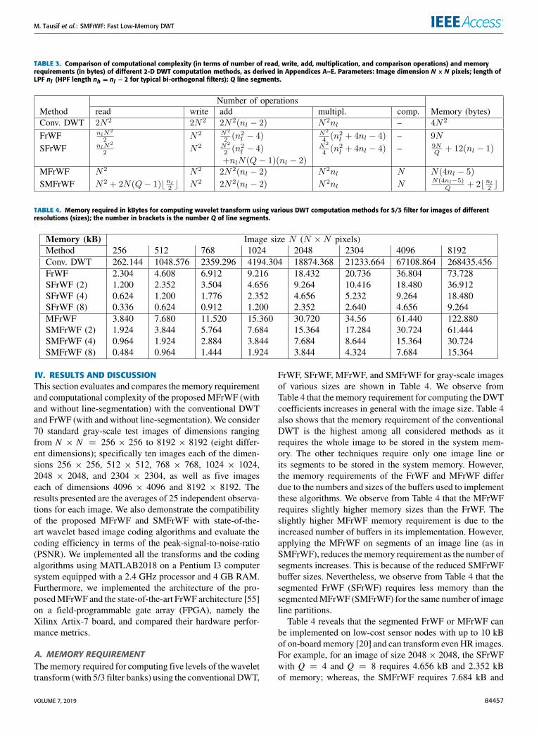
IV. RESULTS AND DISCUSSIONThis section evaluates and compares thememory requirementand computational complexity of the proposed MFrWF (withand without line-segmentation) with the conventional DWTand FrWF (with and without line-segmentation). We consider70 standard gray-scale test images of dimensions rangingfrom N × N = 256 × 256 to 8192 × 8192 (eight differ-ent dimensions); specifically ten images each of the dimen-sions 256 × 256, 512 × 512, 768 × 768, 1024 × 1024,2048 × 2048, and 2304 × 2304, as well as five imageseach of dimensions 4096 × 4096 and 8192 × 8192. Theresults presented are the averages of 25 independent observa-tions for each image. We also demonstrate the compatibilityof the proposed MFrWF and SMFrWF with state-of-the-art wavelet based image coding algorithms and evaluate thecoding efficiency in terms of the peak-signal-to-noise-ratio(PSNR). We implemented all the transforms and the codingalgorithms using MATLAB2018 on a Pentium I3 computersystem equipped with a 2.4 GHz processor and 4 GB RAM.Furthermore, we implemented the architecture of the pro-posedMFrWF and the state-of-the-art FrWF architecture [55]on a field-programmable gate array (FPGA), namely theXilinx Artix-7 board, and compared their hardware perfor-mance metrics.
A. MEMORY REQUIREMENTThememory required for computing five levels of the wavelettransform (with 5/3 filter banks) using the conventional DWT,
FrWF, SFrWF, MFrWF, and SMFrWF for gray-scale imagesof various sizes are shown in Table 4. We observe fromTable 4 that the memory requirement for computing the DWTcoefficients increases in general with the image size. Table 4also shows that the memory requirement of the conventionalDWT is the highest among all considered methods as itrequires the whole image to be stored in the system mem-ory. The other techniques require only one image line orits segments to be stored in the system memory. However,the memory requirements of the FrWF and MFrWF differdue to the numbers and sizes of the buffers used to implementthese algorithms. We observe from Table 4 that the MFrWFrequires slightly higher memory sizes than the FrWF. Theslightly higher MFrWF memory requirement is due to theincreased number of buffers in its implementation. However,applying the MFrWF on segments of an image line (as inSMFrWF), reduces thememory requirement as the number ofsegments increases. This is because of the reduced SMFrWFbuffer sizes. Nevertheless, we observe from Table 4 that thesegmented FrWF (SFrWF) requires less memory than thesegmentedMFrWF (SMFrWF) for the same number of imageline partitions.
Table 4 reveals that the segmented FrWF or MFrWF canbe implemented on low-cost sensor nodes with up to 10 kBof on-board memory [20] and can transform even HR images.For example, for an image of size 2048 × 2048, the SFrWFwith Q = 4 and Q = 8 requires 4.656 kB and 2.352 kBof memory; whereas, the SMFrWF requires 7.684 kB and
VOLUME 7, 2019 84457
M. Tausif et al.: SMFrWF: Fast Low-Memory DWT
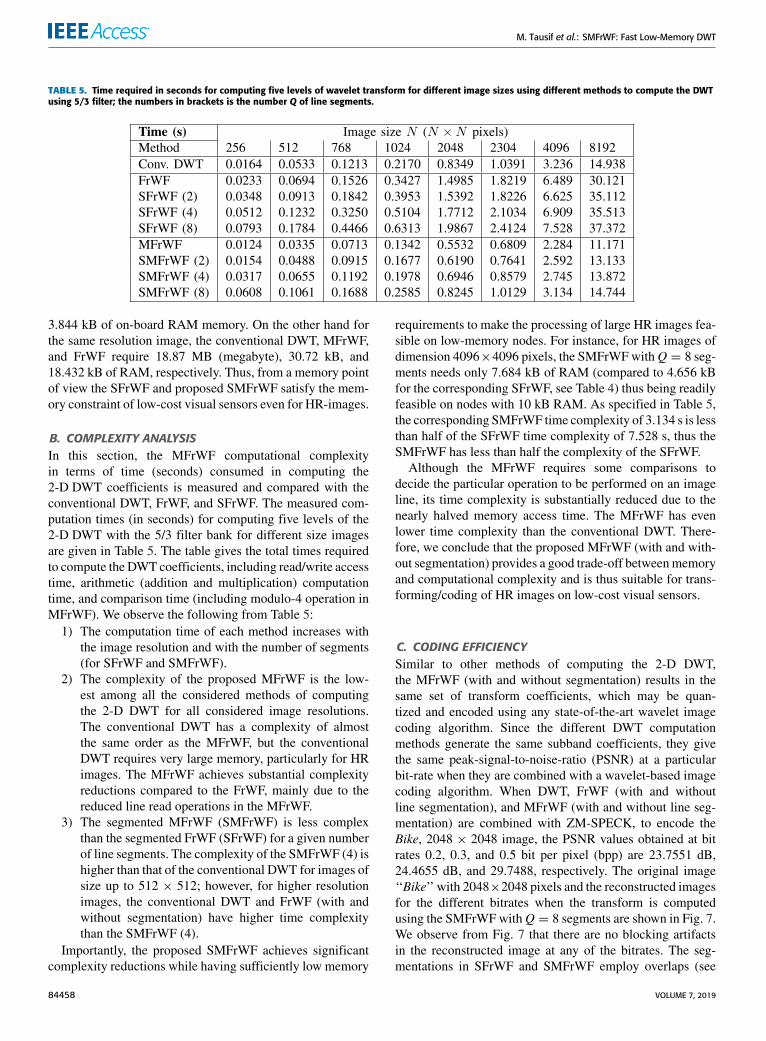
TABLE 5. Time required in seconds for computing five levels of wavelet transform for different image sizes using different methods to compute the DWTusing 5/3 filter; the numbers in brackets is the number Q of line segments.
3.844 kB of on-board RAM memory. On the other hand forthe same resolution image, the conventional DWT, MFrWF,and FrWF require 18.87 MB (megabyte), 30.72 kB, and18.432 kB of RAM, respectively. Thus, from a memory pointof view the SFrWF and proposed SMFrWF satisfy the mem-ory constraint of low-cost visual sensors even for HR-images.
B. COMPLEXITY ANALYSISIn this section, the MFrWF computational complexityin terms of time (seconds) consumed in computing the2-D DWT coefficients is measured and compared with theconventional DWT, FrWF, and SFrWF. The measured com-putation times (in seconds) for computing five levels of the2-D DWT with the 5/3 filter bank for different size imagesare given in Table 5. The table gives the total times requiredto compute the DWT coefficients, including read/write accesstime, arithmetic (addition and multiplication) computationtime, and comparison time (including modulo-4 operation inMFrWF). We observe the following from Table 5:1) The computation time of each method increases with
the image resolution and with the number of segments(for SFrWF and SMFrWF).
2) The complexity of the proposed MFrWF is the low-est among all the considered methods of computingthe 2-D DWT for all considered image resolutions.The conventional DWT has a complexity of almostthe same order as the MFrWF, but the conventionalDWT requires very large memory, particularly for HRimages. The MFrWF achieves substantial complexityreductions compared to the FrWF, mainly due to thereduced line read operations in the MFrWF.
3) The segmented MFrWF (SMFrWF) is less complexthan the segmented FrWF (SFrWF) for a given numberof line segments. The complexity of the SMFrWF (4) ishigher than that of the conventional DWT for images ofsize up to 512 × 512; however, for higher resolutionimages, the conventional DWT and FrWF (with andwithout segmentation) have higher time complexitythan the SMFrWF (4).
Importantly, the proposed SMFrWF achieves significantcomplexity reductions while having sufficiently low memory
requirements to make the processing of large HR images fea-sible on low-memory nodes. For instance, for HR images ofdimension 4096×4096 pixels, the SMFrWFwithQ = 8 seg-ments needs only 7.684 kB of RAM (compared to 4.656 kBfor the corresponding SFrWF, see Table 4) thus being readilyfeasible on nodes with 10 kB RAM. As specified in Table 5,the corresponding SMFrWF time complexity of 3.134 s is lessthan half of the SFrWF time complexity of 7.528 s, thus theSMFrWF has less than half the complexity of the SFrWF.
Although the MFrWF requires some comparisons todecide the particular operation to be performed on an imageline, its time complexity is substantially reduced due to thenearly halved memory access time. The MFrWF has evenlower time complexity than the conventional DWT. There-fore, we conclude that the proposed MFrWF (with and with-out segmentation) provides a good trade-off betweenmemoryand computational complexity and is thus suitable for trans-forming/coding of HR images on low-cost visual sensors.
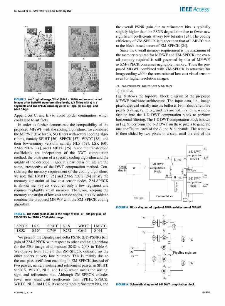
C. CODING EFFICIENCYSimilar to other methods of computing the 2-D DWT,the MFrWF (with and without segmentation) results in thesame set of transform coefficients, which may be quan-tized and encoded using any state-of-the-art wavelet imagecoding algorithm. Since the different DWT computationmethods generate the same subband coefficients, they givethe same peak-signal-to-noise-ratio (PSNR) at a particularbit-rate when they are combined with a wavelet-based imagecoding algorithm. When DWT, FrWF (with and withoutline segmentation), and MFrWF (with and without line seg-mentation) are combined with ZM-SPECK, to encode theBike, 2048 × 2048 image, the PSNR values obtained at bitrates 0.2, 0.3, and 0.5 bit per pixel (bpp) are 23.7551 dB,24.4655 dB, and 29.7488, respectively. The original image‘‘Bike’’ with 2048×2048 pixels and the reconstructed imagesfor the different bitrates when the transform is computedusing the SMFrWFwithQ = 8 segments are shown in Fig. 7.We observe from Fig. 7 that there are no blocking artifactsin the reconstructed image at any of the bitrates. The seg-mentations in SFrWF and SMFrWF employ overlaps (see
84458 VOLUME 7, 2019
M. Tausif et al.: SMFrWF: Fast Low-Memory DWT
FIGURE 7. (a) Original image ‘Bike’ (2048× 2048) and reconstructedimages after SMFrWF transform (five levels, 5/3 filter) with Q = 8segments and ZM-SPECK encoding at (b) 0.1 bpp, (c) 0.3 bpp, and(d) 0.5 bpp.
Appendices C. and E.) to avoid border continuities, whichcould lead to artifacts.
In order to further demonstrate the compatibility of theproposed MFrWF with the coding algorithms, we combinedthe MFrWF (five levels, 5/3 filter) with several coding algo-rithms, namely SPIHT [56], SPECK [57], WBTC [58], andtheir low-memory versions namely NLS [59], LSK [60],ZM-SPECK [24], and LMBTC [25]. Since the transformedcoefficients are independent of the DWT computationmethod, the bitstream of a specific coding algorithm and thequality of the decoded images at a particular bit rate are thesame, irrespective of the DWT computation method. Con-sidering the memory requirement of the coding algorithms,we note that LMBTC [25] and ZM-SPECK [24] satisfy thememory constraint of low-cost sensor nodes. ZM-SPECKis almost memoryless (requires only a few registers) andrequires negligibly small memory. Therefore, keeping thememory constraint of low-cost sensor nodes, it is advisable tocombine the proposed MFrWF with the ZM-SPECK codingalgorithm.
TABLE 6. BD-PSNR gains in dB in the range of 0.01–0.1 bits per pixel ofZM-SPECK for 2048× 2048 Bike image.
We present the Bjontegaard delta PSNR (BD-PSNR) [61]gain of ZM-SPECK with respect to other coding algorithmsfor the Bike image of dimension 2048 × 2048 in Table 6.We observe from Table 6 that ZM-SPECK outperforms theother coders at very low bit rates. This is mainly due tothe one-pass coefficient encoding in ZM-SPECK (instead oftwo passes, namely sorting and refinement passes in SPIHT,SPECK, WBTC, NLS, and LSK) which mixes the sorting,sign, and refinement bits. Although ZM-SPECK encodesfewer new significant coefficients than SPIHT, SPECK,WBTC, NLS, and LSK, it encodes more refinement bits, and
the overall PSNR gain due to refinement bits is typicallyslightly higher than the PSNR degradation due to fewer newsignificant coefficients at very low bit rates [24]. The codingefficiency of ZM-SPECK is higher than that of LMBTC dueto the block-based nature of ZM-SPECK [24].
Since the overall memory requirement is the maximum ofthe memory required for MFrWF and ZM-SPECK, the over-all memory required is still governed by that of MFrWF,as ZM-SPECK consumes negligible memory. Thus, the pro-posed MFrWF combined with ZM-SPECK is attractive forimage codingwithin the constraints of low-cost visual sensorseven for higher resolution images.
D. HARDWARE IMPLEMENTATION1) DESIGNFig. 8 shows the top-level block diagram of the proposedMFrWF hardware architecture. The input data, i.e., imagepixels, are read serially into the bufferB. From this buffer, fivepixels (say x0, x1, x2, x3, and x4) are fed in sliding windowfashion into the 1-D DWT computation block to performhorizontal filtering. The 1-DDWTcomputation block (shownin Fig. 9) performs the 1-D DWT on these pixels to generateone coefficient each of the L and H subbands. The windowis then slided by two pixels in a step, until the end of the
FIGURE 8. Block diagram of top-level FPGA architecture of MFrWF.
FIGURE 9. Schematic diagram of 1-D DWT computation block.
VOLUME 7, 2019 84459

M. Tausif et al.: SMFrWF: Fast Low-Memory DWT
line. The same process is repeated on each line to generatethe L and H subband coefficients according to Eqns. (1)and (2), respectively. For the symmetric 5/3 filter bank, l−2 =l2, l−1 = l1, and h−1 = h1, thus Eqns. (1) and (2) can besimplified for the computation of a single L and H subbandcoefficient for a given line i = 1 to
L(1) = (x0 + x4)l2 + (x1 + x3)l1 + x2l0 (8)
H (1) = (x2 + x4)h1 + x3h0, (9)
FIGURE 10. Schematic diagram of 2-D DWT computation blocks.
as implemented in Fig. 9. The computed L and H subbandcoefficients are saved in registers L_reg and H_reg, respec-tively. The L subband coefficient of L_reg is used as inputfor the 2-D DWT computation block-I (see Fig. 10(a)) tocompute the LL and LH subband coefficients. Similarly, thecoefficient of H_reg is used as input for the 2-D DWT com-putation block-II (see Fig. 10(b)) to compute the HL and HHsubband coefficients. In Fig. 10(a), even and odd lines of theLL subband are computed through Processes 2 and 3, respec-tively (see Section III-B.2). Similarly, the even and odd linesof the HL subband are computed through Processes 2 and 3(see Fig. 10(b)). By inserting pipeline registers after themultipliers and adders shown in Figs. 9–10, the critical pathdelay (CPD) of the proposed MFrWF architecture equals themultiplier delay Tm. The FrWF architecture [55] also usespipeline registers to achieve a CPD of Tm.The described MFrWF hardware architecture is indepen-
dent of the segment size, i.e., accommodates the SMFrWFin a straightforward fashion. The segmentation does notrequire any extra pipeline registers. However, the segmenta-tion reduces the required input pixel buffer size.
2) EVALUATIONWe compare the proposedMFrWF architecture with the exist-ing FrWF architecture [55]. We implemented both architec-tures on the same Xilinx FPGA platform (Family: Artix-7,Device: xc7a100t, Package: csg324, Speed: −3) using iden-tical multipliers, adders, and other components provided bythe Xilinx Artix-7 FPGA family. Both architectures use aninput pixel width of 8 bits and a data-path width of 16 bits.
Comparing the hardware utilizations of both architecturesfor the 5/3 filter, we found that both architectures require fourdigital signal processors (DSPs), and do not require any lookup table RAM (LUTRAM). The MFrWF architecture needsonly one global buffer (BUFG), whereas the FrWF architec-ture needs two BUFGs. Moreover, the MFrWF architecturehas 12 adders and 11multipliers, while the FrWF architecturehas 8 adders and 10 multipliers. As both architectures havethe same CPD of Tm, they can both operate at the maxi-mum frequency of 400 MHz. Additional hardware utilizationcharacteristics are summarized in Table 7, indicating similarnumbers of look up tables, flip flops, and input/output pins.
TABLE 7. Comparison of post-implementation hardware utilization forMFrWF for image dimension 2048× 2048 with 5/3 filter bank.
TABLE 8. Compute cycles as well as power and energy consumption ofSMFrWF for different segment numbers Q for image dimension2048× 2048 with 5/3 filter bank.
We evaluated the total number of cycles and the averagepower consumption for the 2048 × 2048 image size andthe 5/3 filter with the Xilinx Vivado software suite, version2018.2. We evaluated the consumed energy by multiplyingthe number of cycles with the average power consumptionand the clock duration of 2.6 ns. We observe from Table 7that theMFrWF architecture reduces the energy consumptionalmost down to a third of the FrWF energy consumption,which is mainly due to the reduction of the cycles to less thanhalf with the MFrWF. We observe from Table 8 that for anincreasing number of segments Q, the SMFrWF has slightlyincreasing cycle counts and energy consumption. This ismainly because theMFrWF reads a line in one cycle, whereasthe SMFrWF reads a line in Q segments over Q cycles. Thenumber of computation cycles remains essentially unaffectedby the line segmentation.
E. MEMORY-COMPLEXITY TRADE-OFFThe memory and time complexity to compute five levels ofthe wavelet decomposition using the MFrWF and the FrWF(without segmentation (Q = 1) and with Q = 2, 4, and8 segments) as well as the conventional DWT for imagedimension 2048 × 2048 are shown in Fig. 11. We observefrom Fig. 11 that for an increasing number of segments Q,
84460 VOLUME 7, 2019

M. Tausif et al.: SMFrWF: Fast Low-Memory DWT
FIGURE 11. Memory-computational complexity (time) trade-off ofSMFrWF and SFrWF for image size 2048× 2048: Segmentation enablesflexible memory size vs. computation complexity trade-offs. For Q = 1,SFrWF corresponds to FrWF and SMFrWF corresponds to MFrWF.
the FrWF andMFrWFmemory requirements decrease, whilethe time complexities increase. Thus, there exists a trade-offbetween memory and complexity. This is a valuable fea-ture since WMSNs/IoT devices are heterogeneous with vary-ing memory and computational capabilities. The proposedMFrWF provides the flexibility to select the number of linesegments Q according to the available on-board memory andcomputational power of the WMSNs/IoT devices.
V. CONCLUSIONWe have developed and evaluated a novel approach for low-memory computation of the two-dimensional (2-D) discretewavelet transform (DWT) with low computational (time)complexity. The proposed Modified Fractional Wavelet Fil-ter (MFrWF) reduces the computational complexity of theunderlying FrWF by avoiding multiple readings of imagelines, thus reducing the memory access time. Once a line isread from the external SD card, all necessary operations (forconvolution) that are required for computing the 2-D DWTare performed and the results are stored in multiple buffers.Thus, the reduction in memory access time is achieved atthe cost of slightly increased buffer memory. To compensatefor the increased memory, we incorporated line segmenta-tion into the MFrWF, resulting in the Segmented MFrWF(SMFrWF).
We have verified through extensive simulations and hard-ware implementations that the proposed MFrWF has sub-stantially lower complexity than the conventional DWT andFrWF, while generating exactly the same wavelet transformcoefficients. Moreover, the complexities of the SMFrWFfor large HR images are less than for the FrWF and thecorresponding SFrWF. We observed a trade-off between thememory requirement and computational complexity that iscontrolled by the number of line segments, which is a usefulfeature of the SMFrWF. We examined a MFrWF hardwarearchitecture and observed reduced energy consumption com-
pared to an equivalent FrWF architecture. Although, thispaper focused on reducing the computational complexity ofthe forward DWT, the proposed methods are equally applica-ble to the inverse DWT.
There are several interesting future research directionsrelated to DWT computation methods that require only lowmemory and incur low time complexity. One interestingfuture research direction is to examine image transforma-tion and coding in the context of emerging network func-tion virtualization [62]. With network function virtualization,a given physical IoT node or WMSN can support multiplevirtual sensing services in parallel. Our low-memory and lowcomplexity image transform could enable multiple parallelimage sensing functions to be performed on a physical sensornode with limited hardware resources. Moreover, the sens-ing and computing in sensor nodes can become a ‘‘sensinglayer’’ in emerging layered architectures that integrate thecommunication and computing functions in wireless net-works [63], [64]. Future research should examine whetherthe computing resources that have been freed up with theproposed low-complexity DWT method could be utilized formore advanced processing, such as object detection [65],in the sensing layer.
This study has focused on the image wavelet transform,which is a preliminary step towards image compression(source coding). Often, the encoded images need to be trans-mitted over error-prone wireless networks, which requiresome coding for error resilience. For complex wireless net-works with limited coordination, such as wireless sensor net-works, network coding has recently emerged as an attractivecoding approach [66]–[69]. An interesting future researchdirection is to jointly examine image wavelet transform,image coding, and network coding on resource-constrainedsensor nodes.
APPENDIX AANALYSIS OF CONVENTIONAL DWTA. FILTERING AN IMAGE LINEIn this and the subsequent appendices we derive the com-putational complexities in terms of the number of arithmetic(addition and multiplication) operations as well as the num-ber of read and write operations listed in Table 3 for thedifferent computational methods (conventional DWT, FrWF,SFrWF, MFrWF, and SMFrWF) for the 2-D DWT of images.We note that all methods perform the horizontal filteringof image lines in the same way. Therefore, the number ofadditions and multiplications required for computing one lineof the L and H subbands is the same for all consideredDWT computation methods. A coefficient of the L subband isobtained by convolving nl coefficients of an image line withthe LPF according to Eqn. (1), which requires nl−1 additionsand nl+1
2 multiplications (for symmetrical filters). Similarly,the computation of one H subband coefficient (obtained byconvolution with a symmetrical HPF of length nh) requiresnh − 1 additions and nh+1
2 multiplications. Each line of the Land H subbands contains N/2 coefficients. The complexity
VOLUME 7, 2019 84461

M. Tausif et al.: SMFrWF: Fast Low-Memory DWT
of the horizontal filtering of one image line is the sum of thenumbers of the respective arithmetic operations required forthe LPF and HPF filtering operations. Thus, the total com-putation time required for one line of the L and H subbands(assuming nh = nl − 2) is
CLine =N2[2(nl − 2)a+ nlm] , (10)
where a and m denote the time required for one addition andone multiplication, respectively.
B. CONVENTIONAL DWT OF AN IMAGEIn the conventional DWT, each of the N image lines is firsthorizontally filtered, which requires NCLine computations.The subsequent column-wise vertical filtering requires alsoNCLine computations, for a total computation time of 2NCLinefor the 2-D DWT.
During the horizontal filtering in the conventional DWT,each image line of N coefficients needs to be read once; thus,N 2 read operations are required to compute the L and H sub-bands. For the low-memory version of the conventional DWT,the L and H subbands (each subband with N/2 columns, andeach column with N coefficients) resulting from the horizon-tal filtering are written to the SD card (N 2 write operations).For the vertical filtering, each column (consisting ofN coeffi-cients) of the L andH subbands (total ofN columns) needs tobe read from the SD card (N 2 read operations) to compute theLL, LH ,HL, andHH subbands via vertical filtering. The final2-D DWT transform coefficients are written to the SD card.Thus, a total of 2N 2 read operations and 2N 2 write operationsare required for the low-memory version of the conventional2-D DWT computation method, which requires N 2 memoryelements for transform coefficients, equivalent to 4N 2 bytesof memory (for floating point computations). An alternativeversion of the conventional DWT computation avoids thewriting of the L and H subbands to the SD card, by stor-ing them in N 2 additional memory elements for transformcoefficients (4N 2 bytes), for a total of 8 N 2 bytes of memory.Since this study focuses on low-memory settings, we considerthe low-memory version of the conventional DWT with 4N 2
bytes of memory for comparisons.We note that in the other DWT computation methods,
the lines after horizontal filtering are multiplied by filter coef-ficients and saved in RAM buffers. The buffers are updatedthrough successive operations to compute the LL, LH , HL,and HH subbands, and the final results are written to the SDcard. Thus, these other DWT computation methods avoid thewriting of the L or H subbands to the SD card and requiretherefore only N 2 write operations.
APPENDIX BFrWF ANALYSISA. ANALYSIS OF FrWF ARITHMETIC OPERATIONSThe FrWF works on the basis of a VFA consisting of nl lines;the VFA is shifted by two image lines at a time. We firstevaluate the time required for the arithmetic operations in
a VFA. The horizontal filtering of a VFA requires nlCLineoperations, with CLine given by Eqn. (10). From a VFA, oneline each of the LL, LH , HL, and HH subbands will be com-puted. For computing a line of the LL and HL subbands, nlrows (after 1-D horizontal filtering) need to be multiplied bythe LPF coefficients (depending on the line index in the VFA,each rowwill bemultiplied by a specific filter coefficient) andthen added together. Thus, computing one line of the LL andHL subbands requires
CLL_HL = N [(nl − 1)a+ nlm] . (11)
Similarly, for computing one line of the LH and HH sub-bands, nh rows (after 1-D horizontal filtering) need to bemultiplied by the HPF filter coefficients (depending on theline index in VFA, each row will be multiplied by a specificfilter coefficient) and then added together. The computationtime required for computing one line of LH andHH subbands(considering nh = nl − 2) is
CLH_HH = N [(nl − 3)a+ (nl − 2)m]. (12)
The total computation time (for arithmetic operations)required for a VFA is the sum of nlCLine as well as Eqns. (11)and (12). The VFA is shifted N/2 times in order to coverthe entire image, resulting in the total arithmetic computationtime
CArithm_FrWF =N 2
2(n2l −4)a+
N 2
4(n2l +4nl−4)m. (13)
B. ANALYSIS OF FrWF READ OPERATIONSDuring vertical filtering in the 2-D DWT, row g of the LLsubband is computed according to
LL(g) =j=b nl2 c∑j=−b nl2 c
ljL(2g+ j− 1); g = 1, 2, . . . ,N2
, (14)
whereby we denote row 2g+j−1 of the L subband by L(2g+j−1) and denote LPF coefficient j by lj. In the FrWF, nl linesof the L subband are required to compute one line of the LLsubband. In order to verify that even these lines are to be readmultiple times, consider the computation of three consecutiverows, say rows g, g + 1, and g + 2 of the LL subband usinga 5/3 filter (nl = 5). For these three lines, Eqn. (14) may bewritten in expanded form as
LL(g) = l−2L(2g− 3)+ l−1L(2g− 2)
+l0L(2g− 1)+ l1L(2g)+ l2L(2g+ 1) (15)
LL(g+ 1) = l−2L(2g− 1)+ l−1L(2g)+ l0L(2g+ 1)
+l1L(2g+ 2)+ l2L(2g+ 3) (16)
LL(g+ 2) = l−2L(2g+ 1)+ l−1L(2g+ 2)+ l0L(2g+ 3)
+l1L(2g+ 4)+ l2L(2g+ 5). (17)
From these expanded Eqns. (15)–(17), it is clear that the (odd-indexed) row 2g + 1 of the L subband is read thrice, oncefor the computation of each equation, and its elements are
84462 VOLUME 7, 2019
M. Tausif et al.: SMFrWF: Fast Low-Memory DWT
multiplied by l2, l0, and l−2, respectively. Similarly, the (even-indexed) row 2g + 2 of the L subband is read twice, to bemultiplied by l1 and l−1. The HL subband is computed ina similar way and Eqns. (14)–(17) can be re-used, exceptfor replacing the L subband coefficients by the H subbandcoefficients.
Similarly, it can be demonstrated that the LH and HHsubband coefficients are computed by convolving the L andH subbands with the HPF of length nh (nh = 3 for 5/3 filterbank), for which odd-indexed lines are read twice (once to bemultiplied by h−1 and once by h1) and even indexed lines areread once and multiplied by the h0 filter coefficient.Thus, we conclude that the FrWF requires multiple read-
ings of image lines for the computation of the vertical con-volution. The number of times a line is read varies between(nh − 1)/2 and (nl + 1)/2, according to the filter lengths.
A VFA encompasses nl horizontal image lines. The VFA isshifted down by two lines to achieve vertical downsamplingby a factor of two. Overall, the VFA is shifted down N/2times to cover all N image lines [20]. Thus, the FrWF needsto read nlN
2 lines, each with N coefficients for computing
the 2-D DWT of an image, resulting in a total of nlN 2
2 readoperations.
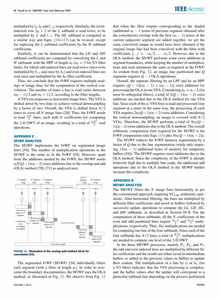
APPENDIX CSFrWF ANALYSISThe SFrWF implements the FrWF on segmented imagelines [54]. The number of multiplication operations in theSFrWF is the same as in the FrWF [54]. However, apartfrom the additions needed by the FrWF, the SFrWF needsnlN (Q−1)(nl−2) extra additions due to the overlap and add(OLA) method [70], [71] as analyzed next.
FIGURE 12. Illustration of the overlap-add method (OLA) forconvolution [54].
The segmented FrWF (SFrWF) [54] individually filterseach segment (with a filter of length nl). In order to over-come the boundary discontinuities, the SFrWF uses the OLAmethod, as illustrated in Fig. 12. We observe from Fig. 12
that when the filter outputs corresponding to the shaded(additional nl − 1 terms of previous segment obtained afterthe convolution) overlap with the first (nl − 1) terms of thecurrent (adjacent) segment are added together, we get thesame convolved output as would have been obtained if theoriginal image line had been convolved with the filter withcoefficients lj, j = −nl/2, . . . , nl/2. However, due to theOLA method, the SFrWF performs some extra additions atsegment boundaries, while keeping the number of multiplica-tions and read operations the same as required in the FrWF.As evident from Fig. 12, an image line partitioned into Qsegments requires Q− 1 OLA operations.
Overall, the separate filtering by an LPF and by an HPFrequires (Q − 1)[(nl − 1) + (nh − 1)] extra additions forprocessing the OLA in one VFA. Considering nh = nl−2 (formost bi-orthogonal filters), a total of 2(Q − 1)(nl − 2) extraadditions are needed due to the OLA method for one VFAline. Since each of the nl VFA lines is read and processed (onesegment at a time) in the same way, the processing of eachVFA requires 2nl(Q−1)(nl−2) extra additions. Consideringthe vertical downsampling, an image is covered with N/2VFAs. Therefore, the SFrWF performs a total of Nnl(Q −1)(nl−2) extra additions due to the OLAmethod. The overallarithmetic computation time required for the SFrWF is theFrWF computation time Eqn. (13) plus Nnl(Q− 1)(nl − 2)a.
The SFrWF reduces the FrWF memory requirement by afactor of Q due to the line segmentation (while only requir-ing 12(nl − 1) additional bytes of memory for temporarybuffers [54]). The SFrWF requires more additions due to theOLA method. Since the complexity of the FrWF is alreadyrelatively high due to multiple line reads, the additional addoperations due to the OLA method in the SFrWF furtherincrease the complexity.
APPENDIX DMFrWF ANALYSISThe MFrWF filters the N image lines horizontally as perthe conventional approach, requiring NCLine arithmetic oper-ations. After horizontal filtering, the lines are multiplied bydifferent filter coefficients and saved in buffers followed bysuccessive update operations to compute the LL, LH , HL,and HH subbands, as described in Section III-B. For thecomputation of these subbands, all the N coefficients of theeven and odd numbered lines require nl−1
2 and nl+12 multi-
plications, respectively. Thus, Nnl multiplications are neededfor computing one line of the four subbands. Since each of thefour subbands has N/2 lines, a total of N 2nl
2 multiplicationsare needed to compute one level of the 2-D DWT.
In the three MFrWF processes, namely P1, P2, and P3,the odd and even indexed lines are multiplied by different fil-ter coefficients and the results are either saved in intermediatebuffers or added to the previous values in buffers to updatetheir content. The multiplication of a line by l2 or h1 (fora 5/3 filter) indicates that the VFA processing is complete,and the buffer values after the update will correspond to aparticular subband line depending on the process performed
VOLUME 7, 2019 84463
M. Tausif et al.: SMFrWF: Fast Low-Memory DWT
on the line. For every image line to be processed, the updateoperations require nl − 2 additions for each line element.For the N coefficients in an image line, N (nl − 2) add oper-ations are needed to implement the update operation of animage line. For an image with N lines, the update operationsrequire a total of N 2(nl − 2) additions.The total number of additions and multiplications needed
for the MFrWF is the sum of NCLine and the computationsneeded for computing the LL, LH , HL, and HH subbands,resulting in Eqn. (5).
APPENDIX ESMFrWF ANALYSISA. ANALYSIS OF SMFrWF ARITHMETIC OPERATIONSSince the SMFrWF uses a slightly different line segmentationapproach than the OLA method of SFrWF (as analyzed indetail in the next subsection), the numbers of arithmeticoperations needed for the SMFrWF are exactly the same asfor the MFrWF.
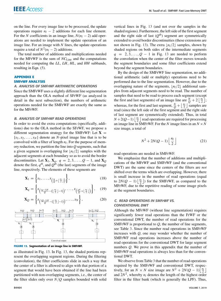
B. ANALYSIS OF SMFrWF READ OPERATIONSIn order to avoid the extra computations (specifically, addi-tions) due to the OLA method in the SFrWF, we propose adifferent segmentation strategy for the SMFrWF: Let X ={x1, x2, . . . , xN } denote an N -pixel image line that is to beconvolved with a filter of length nl . For the purpose of mem-ory reduction, we partition the line intoQ segments, such thata given segment is overlapping for bnl/2c samples with theadjacent segments at each boundary so as to avoid the borderdiscontinuities. Let X1, Xq, q = 2, 3, . . . ,Q − 1, and XQdenote the first, qth, and Qth (the last) segments of the imageline, respectively. The elements of these segments are
X1 =
{x1, . . . , x(N
Q+⌊ nl
2
⌋)} , (18)
Xq =
{x( (q−1)N
Q −(⌊ nl
2
⌋−1)), . . . , x( qN
Q +⌊ nl
2
⌋)} , (19)
XQ =
{x( (Q−1)N
Q −(⌊ nl
2
⌋−1)), . . . , xN
}, (20)
FIGURE 13. Segmentation of an image line in SMFrWF.
as illustrated in Fig. 13. In Fig. 13, the shaded portions rep-resent the overlapping segment regions. During the filtering(convolution), the filter coefficients slide in such a way thatthe center of a filter is allowed to align with that portion of asegment that would have been obtained if the line had beenpartitioned with non-overlapping segments, i.e., the center ofthe filter slides only over N/Q samples bounded with solid
vertical lines in Fig. 13 (and not over the samples in theshaded regions). Furthermore, the left side of the first segmentand the right side of last (Qth) segment are symmetricallyextended to avoid border discontinuities (these extensions arenot shown in Fig. 13). The extra bnl/2c samples, shown byshaded regions on both sides of the intermediate segmentsq = 2, 3, . . . ,Q − 1 in Fig. 13 are needed to performthe convolution when the center of the filter moves towardsthe segment boundaries and some filter coefficients extendbeyond the segment boundaries.
By the design of the SMFrWF line segmentation, no addi-tional arithmetic (add or multiply) operations need to beperformed due to the line segmentation. However, due to theoverlapping nature of the segments, bnl/2c additional sam-ples from adjacent segments need to be read. The number ofsamples that need to be read to process each segment (exceptthe first and last segments) of an image line are N
Q + 2⌊ nl2
⌋;
whereas, for the first and last segment, NQ +⌊ nl2
⌋samples are
read (since the left side of the first segment and the right sideof last segment are symmetrically extended). Thus, in totalN+2(Q−1)
⌊ nl2
⌋read operations are required for processing
an image line in SMFrWF. For the N image lines in an N ×Nsize image, a total of
N 2+ 2N (Q− 1)
⌊nl2
⌋(21)
read operations are needed in SMFrWF.We emphasize that the number of additions and multipli-
cations of the MFrWF and SMFrWF (and the conventionalDWT) are the same since the centers of the filters are notshifted over the terms which are overlapping. However, thereis small increase in the number of read operations (equalto 2N (Q − 1)
⌊ nl2
⌋) for the SMFrWF, as compared to the
MFrWF, due to the repetitive reading of some image pixelsat the segment boundaries.
C. READ OPERATIONS IN SMFrWF VS.CONVENTIONAL DWTAlthough the MFrWF (without line segmentation) requiressignificantly fewer read operations than the FrWF or theconventional DWT, the number of read operations for theSMFrWF is proportional to Q, the number of line segments,see Table 3. Since the number read operations in SMFrWFincreases with Q, one may wonder whether the number ofSMFrWF read operations increases above the number ofread operations for the conventional DWT for large segmentnumbers Q. We prove in this appendix that the number ofSMFrWF read operations is always less than for the conven-tional DWT.
We observe fromTable 3 that the number of read operationsrequired by the SMFrWF and conventional DWT, respec-tively, for an N × N size image are N 2
+ 2N (Q − 1)⌊ nl2
⌋and 2N 2, whereby nl denotes the length of the highest orderfilter in the filter bank (which is generally the LPF). Thus,
84464 VOLUME 7, 2019

M. Tausif et al.: SMFrWF: Fast Low-Memory DWT
it is sufficient to prove that
(Q− 1)2⌊nl2
⌋< N . (22)
Considering the largest possible number of segments Q =N
nl+2bnl2 c
for a given image size (with N pixels per line),(N
nl + 2b nl2 c− 1
)2⌊nl2
⌋< N (23)
⇔ −2⌊nl2
⌋ (nl + 2
⌊nl2
⌋)< Nnl, (24)
which holds true for all positive integers N and nl .
REFERENCES[1] J. Jiang, X. Ma, C. Chen, T. Lu, Z. Wang, and J. Ma, ‘‘Single image
super-resolution via locally regularized anchored neighborhood regressionand nonlocal means,’’ IEEE Trans. Multimedia, vol. 19, no. 1, pp. 15–26,Jan. 2017.
[2] M. Elhoseny, G. Ramírez-González, O. M. Abu-Elnasr, S. A. Shawkat,A. N, and A. Farouk, ‘‘Secure medical data transmission model forIoT-based healthcare systems,’’ IEEE Access, vol. 6, pp. 20596–20608,2018.
[3] R. J.Mstafa, K.M. Elleithy, and E. Abdelfattah, ‘‘A robust and secure videosteganography method in DWT-DCT domains based on multiple objecttracking and ECC,’’ IEEE Access, vol. 5, pp. 5354–5365, 2017.
[4] Y. Shu, C. Han, M. Lv, and X. Liu, ‘‘Fast super-resolution ultrasoundimaging with compressed sensing reconstruction method and single planewave transmission,’’ IEEE Access, vol. 6, pp. 39298–39306, 2018.
[5] H. Zheng, K. Zeng, D. Guo, J. Ying, Y. Yang, X. Peng, F. Huang,Z. Chen, and X. Qu, ‘‘Multi-contrast brain MRI image super-resolutionwith gradient-guided edge enhancement,’’ IEEE Access, vol. 6,pp. 57856–57867, 2018.
[6] G. Latif, D. N. F. A. Iskandar, J. M. Alghazo, and N. Mohammad,‘‘Enhanced MR image classification using hybrid statistical and waveletsfeatures,’’ IEEE Access, vol. 7, pp. 9634–9644, 2019.
[7] S. A. Azzouzi, A. Vidal-Pantaleoni, and H. A. Bentounes, ‘‘Monitor-ing desertification in Biskra, Algeria using Landsat 8 and Sentinel-1Aimages,’’ IEEE Access, vol. 6, pp. 30844–30854, 2018.
[8] G. Chander and B.Markham, ‘‘Revised Landsat-5 TM radiometric calibra-tion procedures and postcalibration dynamic ranges,’’ IEEE Trans. Geosci.Remote Sens., vol. 41, no. 11, pp. 2674–2677, Nov. 2003.
[9] S. Li and G. Jiang, ‘‘Land surface temperature retrieval from Landsat-8data with the generalized split-window algorithm,’’ IEEE Access, vol. 6,pp. 18149–18162, 2018.
[10] S. C. Park, M. K. Park, and M. G. Kang, ‘‘Super-resolution image recon-struction: A technical overview,’’ IEEE Signal Process.Mag., vol. 20, no. 3,pp. 21–36, May 2003.
[11] A. Madanayake, R. J. Cintra, V. Dimitrov, F. Bayer, K. A. Wahid,A. Edirisuriya, U. Potluri, S. Madishetty, and N. Rajapaksha, ‘‘Low-powerVLSI architectures for DCT/DWT: Precision vs approximation for HDvideo, biomedical, and smart antenna applications,’’ IEEE Circuits Syst.Mag., vol. 15, no. 1, pp. 25–47, 1st Quart., 2015.
[12] C. Chrysafis and A. Ortega, ‘‘Line-based, reduced memory, waveletimage compression,’’ IEEE Trans. Image Process., vol. 9, no. 3,pp. 378–389, Mar. 2000.
[13] J. Oliver and M. Perez Malumbres, ‘‘On the design of fast wavelet trans-form algorithms with low memory requirements,’’ IEEE Trans. CircuitsSyst. Video Technol., vol. 18, no. 2, pp. 237–248, Feb. 2008.
[14] P. Cosman and K. Zeger, ‘‘Memory constrained wavelet based imagecoding,’’ IEEE Signal Process. Lett., vol. 5, no. 9, pp. 221–223, Sep. 1998.
[15] I. F. Akyildiz, T. Melodia, and K. R. Chowdhury, ‘‘Wireless multimediasensor networks: Applications and testbeds,’’ Proc. IEEE, vol. 96, no. 10,pp. 1588–1605, Oct. 2008.
[16] M. A. Jan, M. Usman, X. He, and A. U. Rehman, ‘‘SAMS: A seamless andauthorized multimedia streaming framework for WMSN-based IoMT,’’IEEE Internet Things J., vol. 6, no. 2, pp. 1576–1583, Apr. 2019.
[17] H. Tao, M. Z. A. Bhuiyan, A. N. Abdalla, M. M. Hassan, J. M. Zain, andT. Hayajneh, ‘‘Secured data collection with hardware-based ciphersfor IoT-based healthcare,’’ IEEE Internet Things J., vol. 6, no. 1,pp. 410–420, Feb. 2019.
[18] M. M. Rana and W. Xiang, ‘‘IoT communications network for wirelesspower transfer system state estimation and stabilization,’’ IEEE InternetThings J., vol. 5, no. 5, pp. 4142–4150, Oct. 2018,
[19] O. Elijah, T. A. Rahman, I. Orikumhi, C. Y. Leow, and M. N. Hindia,‘‘An overview of Internet of Things (IoT) and data analytics in agricul-ture: Benefits and challenges,’’ IEEE Internet Things J., vol. 5, no. 5,pp. 3758–3773, Oct. 2018.
[20] S. Rein and M. Reisslein, ‘‘Low-memory wavelet transforms for wirelesssensor networks: A tutorial,’’ IEEE Commun. Surveys Tuts., vol. 13, no. 2,pp. 291–307, 2nd Quart., 2011.
[21] S. Rein and M. Reisslein, ‘‘Performance evaluation of the fractionalwavelet filter: A low-memory image wavelet transform for multimediasensor networks,’’ Ad Hoc Netw., vol. 9, no. 4, pp. 482–496, Jun. 2011.
[22] Y. Chung-Hsien, W. Jia-Ching, W. Jhing-Fa, and C.-W. Chang, ‘‘A block-based architecture for lifting scheme discrete wavelet transform,’’IEICE Trans. Fundam. Electr., Commun. Comput. Sci., vol. 90, no. 5,pp. 1062–1071, May 2007.
[23] L. W. Chew, W. C. Chia, L.-M. Ang, and K. P. Seng, ‘‘Very low-memorywavelet compression architecture using strip-based processing for imple-mentation in wireless sensor networks,’’ EURASIP J. Embedded Syst.,vol. 2009, no. 479281, pp. 1–16, Dec. 2009.
[24] N. R. Kidwai, E. Khan, and M. Reisslein, ‘‘ZM-SPECK: A fast and mem-oryless image coder for multimedia sensor networks,’’ IEEE Sensors J.,vol. 16, no. 8, pp. 2575–2587, Apr. 2016.
[25] M. Tausif, N. R. Kidwai, E. Khan, and M. Reisslein, ‘‘FrWF-basedLMBTC: Memory-efficient image coding for visual sensors,’’ IEEE Sen-sors J., vol. 15, no. 11, pp. 6218–6228, Nov. 2015.
[26] S. A. Rein, F. H. Fitzek, C. Gühmann, and T. Sikora, ‘‘Evaluation ofthe wavelet image two-line coder: A low complexity scheme for imagecompression,’’ Signal Process. Image Commun., vol. 37, pp. 58–74,Sep. 2015.
[27] M. Vishwanath, ‘‘The recursive pyramid algorithm for the discretewavelet transform,’’ IEEE Trans. Signal Process., vol. 42, no. 3,pp. 673–676, Mar. 1994.
[28] L. Ye, J. Guo, B. Nutter, and S. Mitra, ‘‘Low-memory-usage imagecoding with line-based wavelet transform,’’ Opt. Eng., vol. 50, no. 2,pp. 027005-1–027005-11, Feb. 2011.
[29] Y. Bao and C.-C. J. Kuo, ‘‘Design of wavelet-based image codec inmemory-constrained environment,’’ IEEE Trans. Circuits Syst. Video Tech-nol., vol. 11, no. 5, pp. 642–650, May 2001.
[30] C.-K. Hu, W.-M. Yan, and K.-L. Chung, ‘‘Efficient cache-based spatialcombinative lifting algorithm for wavelet transform,’’ Signal Process.,vol. 84, no. 9, pp. 1689–1699, 2004.
[31] V. Ratnakar, ‘‘TROBIC: Two-row buffer image compression,’’ in Proc.IEEE Int. Conf. Acoust., Speech, Signal Proc. (ICASSP), vol. 6, Mar. 1999,pp. 3133–3136.
[32] L. W. Chew, W. C. Chia, L.-M. Ang, and K. P. Seng, ‘‘Low–memory videocompression architecture using strip–based processing for implementationin wireless multimedia sensor networks,’’ Int. J. Sensor Netw., vol. 11,no. 1, pp. 33–47, Jan. 2012.
[33] W. C. Chia, L. W. Chew, L.-M. Ang, and K. P. Seng, ‘‘Low memory imagestitching and compression for WMSN using strip-based processing,’’ Int.J. Sensor Netw., vol. 11, no. 1, pp. 22–32, Jan. 2012.
[34] L. W. Chew, L. M. Ang, and K. P. Seng, ‘‘New virtual SPIHT treestructures for very low memory strip-based image compression,’’ IEEESignal Process. Lett., vol. 15, pp. 389–392, 2008.
[35] R. K. Bhattar, K. R. Ramakrishnan, and K. S. Dasgupta, ‘‘Stripbased coding for large images using wavelets,’’ Signal Process., ImageCommun., vol. 17, no. 6, pp. 441–456, Jul. 2002.
[36] L. Ye and Z. Hou, ‘‘Memory efficient multilevel discrete wavelet trans-form schemes for JPEG2000,’’ IEEE Trans. Circuits Syst. Video Technol.,vol. 25, no. 11, pp. 1773–1785, Nov. 2015.
[37] C.-T. Huang, P.-C. Tseng, and L.-G. Chen, ‘‘Generic RAM-based archi-tectures for two-dimensional discrete wavelet transform with line-basedmethod,’’ IEEE Trans. Circuits Syst. Video Technol., vol. 15, no. 7, pp. 910–920, Jul. 2005.
[38] Y.-H. Seo and D.-W. Kim, ‘‘VLSI architecture of line-based lifting wavelettransform for motion JPEG2000,’’ IEEE J. Solid-State Circuits, vol. 42,no. 2, pp. 431–440, Feb. 2007.
[39] W.-H. Chang, Y.-S. Lee, W.-S. Peng, and C.-Y. Lee, ‘‘A line-based, mem-ory efficient and programmable architecture for 2D DWT using liftingscheme,’’ inProc IEEE Int. Symp. Circuits Syst. (ISCAS), vol. 4, May 2001,pp. 330–333.
VOLUME 7, 2019 84465

M. Tausif et al.: SMFrWF: Fast Low-Memory DWT
[40] C.-Y. Xiong, J.-W. Tian, and J. Liu, ‘‘Efficient high-speed/low-powerline-based architecture for two-dimensional discrete wavelet transformusing lifting scheme,’’ IEEE Trans. Circuits Syst. Video Technol., vol. 16,no. 2, pp. 309–316, Feb. 2006.
[41] B. K. Mohanty, A. Mahajan, and P. K. Meher, ‘‘Area- and power-efficientarchitecture for high-throughput implementation of lifting 2-D DWT,’’IEEE Trans. Circuits Syst. II, Exp. Briefs, vol. 59, no. 7, pp. 434–438,Jul. 2012.
[42] C. Cheng and K. K. Parhi, ‘‘High-speed VLSI implementation of 2-Ddiscrete wavelet transform,’’ IEEE Trans. Signal Process., vol. 56, no. 1,pp. 393–403, Jan. 2008.
[43] K. Andra, C. Chakrabarti, and T. Acharya, ‘‘A VLSI architecture forlifting-based forward and inverse wavelet transform,’’ IEEE Trans. SignalProcess., vol. 50, no. 4, pp. 966–977, Apr. 2002.
[44] B.-F. Wu and C.-F. Lin, ‘‘Memory-efficient architecture forJPEG 2000 coprocessor with large tile image,’’ IEEE Trans. Circuits Syst.II, Exp. Briefs, vol. 53, no. 4, pp. 304–308, Apr. 2006.
[45] A. D. Darji, S. S. Kushwah, S. N. Merchant, and A. N. Chandorkar,‘‘High-performance hardware architectures for multi-level lifting-baseddiscrete wavelet transform,’’ EURASIP J. Image Video Process., vol. 2014,nos. 1–19, p. 47, Oct. 2014.
[46] A.Mason, J. Li, K. Thomson, Y. Suhail, and K. Oweiss, ‘‘Design optimiza-tion of integer lifting DWT circuitry for implantable neuroprosthetics,’’in Proc. 3rd IEEE/EMBS Special Topic Conf. Microtechnol. Med. Biol.,May 2005, pp. 136–139.
[47] B. K. Mohanty and P. K. Meher, ‘‘Memory-efficient high-speedconvolution-based generic structure formultilevel 2-DDWT,’’ IEEE Trans.Circuits Syst. Video Technol., vol. 23, no. 2, pp. 353–363, Feb. 2013.
[48] Y. Hu and C. C. Jong, ‘‘A memory-efficient high-throughput architecturefor lifting-based multi-level 2-D DWT,’’ IEEE Trans. Signal Process.,vol. 61, no. 20, pp. 4975–4987, Oct. 2013.
[49] W. Jiang and A. Ortega, ‘‘Lifting factorization-based discrete wavelettransform architecture design,’’ IEEE Trans. Circuits Syst. VideoTechnol., vol. 11, no. 5, pp. 651–657, May 2001.
[50] C.-T. Huang, P.-C. Tseng, and L.-G. Chen, ‘‘Analysis and VLSI archi-tecture for 1-D and 2-D discrete wavelet transform,’’ IEEE Trans. SignalProcess., vol. 53, no. 4, pp. 1575–1586, Apr. 2005.
[51] B. K. Mohanty and P. K. Meher, ‘‘Memory efficient modular VLSIarchitecture for high throughput and low-latency implementation of mul-tilevel lifting 2-D DWT,’’ IEEE Trans. Signal Process., vol. 59, no. 5,pp. 2072–2084, May 2011.
[52] W. Zhang, Z. Jiang, Z. Gao, and Y. Liu, ‘‘An efficient VLSI architecturefor lifting-based discrete wavelet transform,’’ IEEE Trans. Circuits Syst. II,Exp. Briefs, vol. 59, no. 3, pp. 158–162, Mar. 2012.
[53] W. Sweldens, ‘‘The lifting scheme: A construction of second gener-ation wavelets,’’ SIAM J. Math. Anal., vol. 29, no. 2, pp. 511–546,1998.
[54] M. Tausif, E. Khan, M. Hasan, and M. Reisslein, ‘‘SFrWF: Segmentedfractional wavelet filter based DWT for low memory image coders,’’in Proc. IEEE Uttar Pradesh Section Int. Conf. Electr., Comput. Electr.(UPCON), Oct. 2017, pp. 593–597.
[55] M. Tausif, A. Jain, E. Khan, and M. Hasan, ‘‘Efficient architectures offractional wavelet filter (FrWF) for visual sensors and wearable devices,’’in Proc. IEEE SENSORS, Oct. 2018, pp. 1–4.
[56] A. Said andW. A. Pearlman, ‘‘A new, fast, and efficient image codec basedon set partitioning in hierarchical trees,’’ IEEE Trans. Circuits Syst. VideoTechnol., vol. 6, no. 3, pp. 243–250, Jun. 1996.
[57] W. A. Pearlman, A. Islam, N. Nagaraj, and A. Said, ‘‘Efficient,low-complexity image coding with a set-partitioning embedded blockcoder,’’ IEEE Trans. Circuits Syst. Video Technol., vol. 14, no. 11,pp. 1219–1235, Nov. 2004.
[58] A. A. Moinuddin, E. Khan, andM. Ghanbari, ‘‘Efficient algorithm for verylow bit rate embedded image coding,’’ IET Image Process., vol. 2, no. 2,pp. 59–71, Apr. 2008.
[59] F. W. Wheeler and W. A. Pearlman, ‘‘SPIHT image compression with-out lists,’’ in Proc. IEEE Conf. Acoust., Speech Signal Process., vol. 4.Jun. 2000, pp. 2047–2050.
[60] M. V. Latte, N. H. Ayachit, and D. K. Deshpande, ‘‘Reduced memorylistless SPECK image compression,’’Digit. Signal Process., vol. 16, no. 6,pp. 817–824, Nov. 2006.
[61] G. Bjontegaard, ‘‘Calculation of average PSNR differences between RDcurves,’’ ITU–Telecommun. Standardization Sector, Video Coding ExpertsGroup, Austin, TX, USA, Tech. Rep. VCEG-M33, ITU-T SG16/Q6,Apr. 2001, pp. 1–4.
[62] K. Han, S. Li, S. Tang, H. Huang, S. Zhao, G. Fu, and Z. Zhu, ‘‘Application-driven end-to-end slicing: When wireless network virtualization orches-trates with NFV-based mobile edge computing,’’ IEEE Access, vol. 6,pp. 26567–26577, 2018.
[63] G. Mokhtari, A. Anvari-Moghaddam, and Q. Zhang, ‘‘A new layeredarchitecture for future big data-driven smart homes,’’ IEEE Access, vol. 7,pp. 19002–19012, 2019.
[64] P. Shantharama, A. S. Thyagaturu, N. Karakoc, L. Ferrari, M. Reisslein,and A. Scaglione, ‘‘LayBack: SDN management of multi-access edgecomputing (MEC) for network access services and radio resource sharing,’’IEEE Access, vol. 6, pp. 57545–57561, 2018.
[65] J. Ren, Y. Guo, D. Zhang, Q. Liu, and Y. Zhang, ‘‘Distributed and efficientobject detection in edge computing: Challenges and solutions,’’ IEEENetw., vol. 32, no. 6, pp. 137–143, Nov./Dec. 2018.
[66] Y. Gao, X. Xu, Y. L. Guan, and P. H. J. Chong, ‘‘V2X content distributionbased on batched network coding with distributed scheduling,’’ IEEEAccess, vol. 6, pp. 59449–59461, 2018.
[67] D. E. Lucani, M. V. Pedersen, D. Ruano, C. W. Sørensen,F. H. P. Fitzek, J. Heide, O. Geil, V. Nguyen, and M. Reisslein, ‘‘Fulcrum:Flexible network coding for heterogeneous devices,’’ IEEE Access, vol. 6,pp. 77890–77910, 2018.
[68] A. Naeem, M. H. Rehmani, Y. Saleem, I. Rashid, and N. Crespi, ‘‘Net-work coding in cognitive radio networks: A comprehensive survey,’’ IEEECommun. Surveys Tuts., vol. 19, no. 3, pp. 1945–1973, 3rd Quart., 2017.
[69] X. Shao, C. Wang, C. Zhao, and J. Gao, ‘‘Traffic shaped network cod-ing aware routing for wireless sensor networks,’’ IEEE Access, vol. 6,pp. 71767–71782, 2018.
[70] J. S. Lim, Two-Dimensional Signal and Image Processing. EnglewoodCliffs, NJ, USA: Prentice-Hall, 1990.
[71] J. G. Proakis and D. Manolakis, Digital Signal Processing: Principles,Algorithms and Applications, 4th ed. Delhi, India: Pearson, 2006.
MOHD TAUSIF received the B.Tech. degreein electronics engineering from Gautam BuddhaTechnical University, Lucknow, India, in 2012,and the M.Tech. degree in communication andinformation system from Aligarh Muslim Uni-versity (AMU), Aligarh, India, in 2014, wherehe is currently pursuing the Ph.D. degree. Hisresearch interests include signal processing andlow-complexity image coding algorithms. He hasqualified for the Junior Research Fellowship (JRF)
conducted by University Grants Commission, India, in 2015. He was arecipient of the prestigious Visvesvaraya Fellowship from the Ministry ofInformation and Technology, Government of India, for pursuing the Ph.D.degree.
EKRAM KHAN received the B.Sc.(Eng.) andM.Sc.(Eng.) degrees in electronics engineeringfrom Aligarh Muslim University (AMU), Aligarh,India, in 1991 and 1994, respectively, and thePh.D. degree in electronics engineering from theUniversity of Essex, Colchester, U.K., in 2003.In 1993, he joined the Department of ElectronicsEngineering, AMU,where he has been a Professor,since 2009. He has successfully completed severalresearch projects funded by various agencies in
India and U.K. He spent the summer of 2005 and 2006, as an AcademicVisitor, at the University of Essex (funded by the Royal Society, U.K).He has authored or coauthored over 90 papers in refereed academic journalsand international conference proceedings. His research interests includelow-complexity image/video coding, video transmission over wireless net-works, and biomedical image processing. He is also a Life Member of theInstitution of Electronics and Telecommunication Engineers, India, and theSystems Society of India. He received the Commonwealth Scholarship topursue the Ph.D. degree with the University of Essex. He also received theResearch Award from the IBM J. T. Watson Research Laboratory, USA, forthe best disruptive idea presented at the IEEE ICME 2002, held at EPFL,Switzerland.
84466 VOLUME 7, 2019

M. Tausif et al.: SMFrWF: Fast Low-Memory DWT
MOHD HASAN (M’10–SM’13) received theB.Tech. degree in electronics engineering fromAligarh Muslim University (AMU), India,the M.Tech. degree in integrated electronics andcircuits from the IIT Delhi, India, and the Ph.D.degree from The University of Edinburgh, U.K.He worked as a Visiting Postdoctoral Researcheron a project funded by the prestigious RoyalAcademy of Engineering, U.K., on low-powerfield programmable gate array architecture with
the School of Engineering, The University of Edinburgh. He has been aFull Professor with AMU, since 2005. He has authored over 137 researchpapers in reputed journals and conference proceedings. His research inter-ests include low-power VLSI design, nanoelectronics, spintronics, andbattery-less electronics.
MARTIN REISSLEIN (S’96–M’98–SM’03–F’14)received the Ph.D. degree in systems engineeringfrom the University of Pennsylvania, Philadelphia,in 1998. He is currently a Professor with theSchool of Electrical, Computer, and Energy Engi-neering, Arizona State University (ASU), Tempe.He also chairs the Steering Committee of the IEEETRANSACTIONS ON MULTIMEDIA. He also serves asan Associate Editor for the IEEE TRANSACTIONS
ON MOBILE COMPUTING, IEEE TRANSACTIONS ON
EDUCATION, IEEE ACCESS, and Computer Networks. He is also an AssociateEditor-in-Chief of the IEEE COMMUNICATIONS SURVEYS & TUTORIALS and aCo-Editor-in-Chief of Optical Switching and Networking.
VOLUME 7, 2019 84467