smc pneumatics rsh/rs1h heavy duty stopper cylinder · 2011. 5. 12. · rsh rs1h standard stroke 15...
TRANSCRIPT

Series RSH Series RS1H ����� ��� ���� �������
���� ��� ���� ���� ���
����� �� ��� �� ���� ���� �� ����!���� � ��� "� ����#
����� �� ��� � � ����� �� ��������� �� ��� ������ ������� ���� �� �����
$��� ���� ���� �� �"� % ���� �� �
���� � ������ � ���� �� �� � ����� ����������� ��� � � �!� � ��� �� ����� �� �� �������� ����� ������� " # �� ��� "�� �� �������
$����� �� � �� ����� �� ����
%� ������� �� !��� ��� � ������ �� ����� ���� ������ �� � ���
&� ��� ������ ��������� ������ '�" ����(���"� % ���� ��
&� ��� ������ �����
&���
����� �������
������ ���
�� ��� �'(�
)� *� +� (�,�� ������
�� � '���� �����
$����� ������
-�� ��.�� � /� �
�������� ����� � � �������� !�� �� ���
� ��� )� ������
*�
*+�
������� ���
������ � ����� ��� ���
����� � ��� � � ��� ���
.� ��� � ���� 0 �� ���� ���� �
0 �����# �������
��!������
,�����
-���
����
������
�����
�����
�����
��������
��
0 �������
$����� �� � ��
)(�)
RSQ
RSG
RS�
MI�
Individual-X�
D-�
-X�
P1371-P1434-E.qxd 08.11.17 3:43 PM Page 1401
Courtesy of Steven Engineering, Inc.-230 Ryan Way, South San Francisco, CA 94080-6370-Main Office: (650) 588-9200-Outside Local Area: (800) 258-9200-www.stevenengineering.com
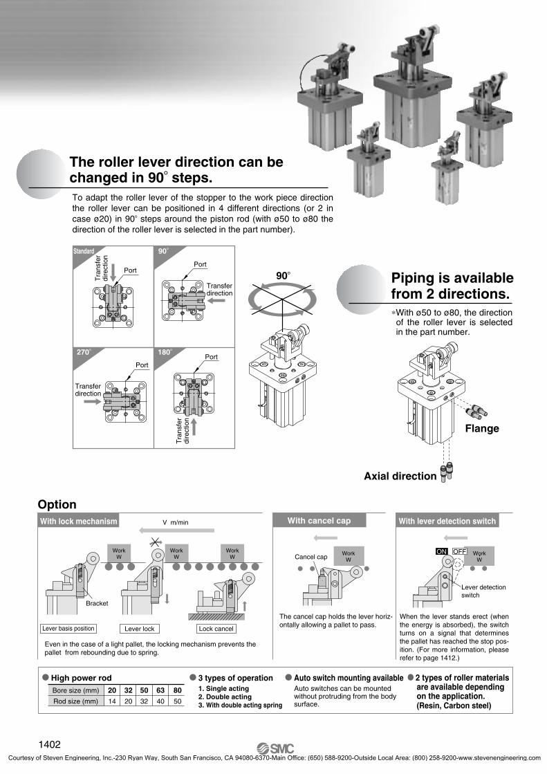
V m/min
OptionWith cancel cap With lever detection switch
WorkW
WorkW
WorkW
Bracket
�Auto switch mounting availableAuto switches can be mounted without protruding from the bodysurface.
�2 types of roller materialsare available dependingon the application.(Resin, Carbon steel)
�3 types of operation1. Single acting2. Double acting3. With double acting spring
�High power rodBore size (mm)
Rod size (mm)
2014
3220
5032
6340
8050
Even in the case of a light pallet, the locking mechanism prevents the pallet from rebounding due to spring.
The roller lever direction can be changed in 90� steps.To adapt the roller lever of the stopper to the work piece direction the roller lever can be positioned in 4 different directions (or 2 in case ø20) in 90� steps around the piston rod (with ø50 to ø80 the direction of the roller lever is selected in the part number).
270�
Port
180�Port
90�
Transferdirection
Transferdirection
Port
Standard
Tra
nsfe
rdi
rect
ion
Tra
nsfe
rdi
rect
ion
Port90� Piping is available
from 2 directions.
Flange
Axial direction
∗With ø50 to ø80, the direction of the roller lever is selected in the part number.
With lock mechanism
Lever basis position Lever lock Lock cancel
Cancel capON OFF
Lever detectionswitch
When the lever stands erect (when the energy is absorbed), the switch turns on a signal that determines the pallet has reached the stop pos-ition. (For more information, please refer to page 1412.)
The cancel cap holds the lever horiz-ontally allowing a pallet to pass.
WorkW
WorkW
1402
P1371-P1434-E.qxd 08.11.17 3:43 PM Page 1402
Courtesy of Steven Engineering, Inc.-230 Ryan Way, South San Francisco, CA 94080-6370-Main Office: (650) 588-9200-Outside Local Area: (800) 258-9200-www.stevenengineering.com

100
200
300
400
500
600
700
10 20 30 40
800
900
1000
1100
1200
1300
100
200
300
400
500
600
700
10 20 30 40
800
900
1000
1100
1200
1300
10
20
30
40
10 20 30 40
50
60
10 20 30 40
70
80
10
20
30
40
50
60
70
80
ø80
ø63
ø50
ø80
ø63
ø50
ø32
ø20
ø32
ø20
0.1
0.2
0.3
0.4
0.5
0.6
0.7
100 200 300 400
0.8
0.9
1.0
5000
0.1
0.2
0.3
0.4
0.5
0.6
0.7
1000 2000 3000 4000
0.8
0.9
1.0
50000
0 0
0 0
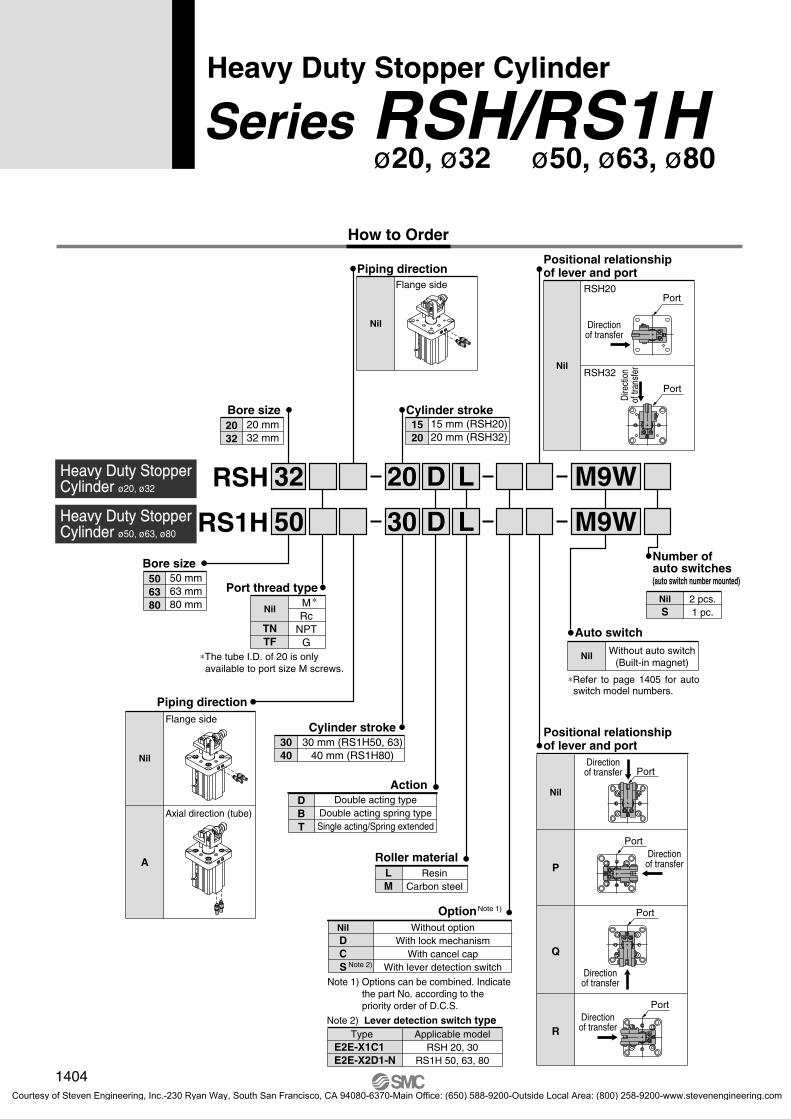
Series RSH/RS1HModel Selection
RS
1H50
RS1
H63
RS1H80
RS
H20
RSH32
*The graphs for the load mass and transfer speed show the values measured at room temperature (20 to 25°C).
Operating Range
Graph q Graph wBore size ø50, ø63, ø80/μ = 0 Bore size ø50, ø63, ø80/μ = 0.1
(Example) Load mass 300 kg, Transfer speed 20 m/min, Friction coefficient μ = 0.1
(How to read graph)In graph [2], find the intersection of the vertical axis representing the mass of 300 kg and the horizontal axis representing the speed of 20 m/min. And select the bore size ø63 positioned within the operating range of the cylinder.
Lateral Load and Operating Pressure
The greater lateral load needs higher cylinder operating pressure. Set the operating pressure by using the graph as a guideline.
RSH20, 32
RS1H50, 63, 80
Graph e Graph rBore size ø20, ø32/μ = 0 Bore size ø20, ø32/μ = 0.1
Load
mas
s m
[kg]
Load
mas
s m
[kg]
Transfer speed υ [m/min]μ = 0
Transfer speed υ [m/min]μ = 0.1
Transfer speed υ [m/min]μ = 0
Load
mas
s m
[kg]
Load
mas
s m
[kg]
Transfer speed υ [m/min]μ = 0.1
Lateral load F [N]
Ope
ratin
g pr
essu
re Z
P [M
Pa]
Lateral load F [N]
Ope
ratin
g pr
essu
re P
[MP
a]
1403
RSQ
RSG
RS�
MI�
Individual-X�
D-�
-X�
P1371-P1434-E.qxd 08.11.17 3:43 PM Page 1403
Courtesy of Steven Engineering, Inc.-230 Ryan Way, South San Francisco, CA 94080-6370-Main Office: (650) 588-9200-Outside Local Area: (800) 258-9200-www.stevenengineering.com
RSH
RS1H M9W
2 pcs.1 pc.
Number of auto switches(auto switch number mounted)
NilS
D
D
L
L
M9W
Auto switch
Nil Without auto switch(Built-in magnet)
∗Refer to page 1405 for auto switch model numbers.
Positional relationship of lever and port
32
50
20
30Heavy Duty StopperCylinder ø50, ø63, ø80
Heavy Duty StopperCylinder ø20, ø32
Nil
P
Q
R
Positional relationship of lever and port
Nil
RSH20
RSH32
Directionof transfer
Port
Port
Piping directionFlange side
Nil
15 mm (RSH20)20 mm (RSH32)
Cylinder stroke1520
30 mm (RS1H50, 63)40 mm (RS1H80)
Cylinder stroke3040
20 mm32 mm
Bore size 2032
50 mm63 mm80 mm
Bore size 506380
Port thread type
Nil
A
Flange side
Axial direction (tube)
Piping direction
Dire
ctio
nof
tran
sfer
Port
Port
Port
Port
Directionof transfer
Directionof transfer
Directionof transfer
Directionof transfer
OptionNote 1)
NilDCS
Without optionWith lock mechanism
With cancel capWith lever detection switch
Note 2) Lever detection switch type TypeE2E-X1C1E2E-X2D1-N
Applicable modelRSH 20, 30
RS1H 50, 63, 80
Note 1) Options can be combined. Indicate the part No. according to the priority order of D.C.S.
Note 2)
Roller materialLM
ResinCarbon steel
ActionDBT
Double acting typeDouble acting spring typeSingle acting/Spring extended
MRc
NPTG
∗
∗The tube I.D. of 20 is only available to port size M screws.
Nil
TNTF
1404
Heavy Duty Stopper Cylinder
ø20, ø32 ø50, ø63, ø80Series RSH/RS1H
How to Order
P1371-P1434-E.qxd 08.11.17 3:43 PM Page 1404
Courtesy of Steven Engineering, Inc.-230 Ryan Way, South San Francisco, CA 94080-6370-Main Office: (650) 588-9200-Outside Local Area: (800) 258-9200-www.stevenengineering.com

Bore size (mm)
Action
Style of rod end
Fluid
Proof pressure
Max. operating pressure
Model RSH RS1H
Ambient and fluid temperature
Lubrication
Cushion
Stroke length tolerance
Mounting
Port sizeRc, NPT, G
Double acting, Double acting spring, Single acting (Spring extended)
Lever with built-in shock absorber type
Air
1.5 MPa
1.0 MPa
�10 to 60�C (No freezing)
Not required (non-lube)
Rubber bumper
Flange
20 32 50 63 80
M5 x 0.8
�
�
(mm)
20
32
50
63
80
Bore size (mm)Model
RSH
RS1H
Standard stroke
15
20
30
30
40
(kg)
Action
Double acting type
Double acting spring type
Single acting spring extended
Rod end configuration
Lever with built-inshock absorber type
Bore size(mm)
20
32
50
63
80
Mass
0.41
0.75
2.03
3.56
6.33
Specifications
Bore size, Standard strokes
Mass
RSH
RS1H
Applicable auto switches/Refer to pages 1719 to 1827 for detailed auto switch specifications.
M9NVM9PVM9BV
M9NWVM9PWVM9BWVM9NAVM9PAVM9BAV
M9NM9PM9B
M9NWM9PWM9BWM9NAM9PAM9BA
Type Special function
24 V
3-wire (NPN)3-wire (PNP)
2-wire3-wire (NPN)3-wire (PNP)
2-wire3-wire (NPN)3-wire (PNP)
2-wire
Yes
Electricalentry
Load voltageWiring
(output)Pre-wiredconnector
Applicable loadDC AC
Auto switch models Lead wire length (m)
Perpendicular In-line0.5(Nil)
3(L)
5(Z)
Grommet
Grommet
���������
���������
���������
�
��
1(M)
���������
���������
�
��
ICcircuit
ICcircuit
ICcircuit
ICcircuit
�
�
�
�
�
�
Relay, PLC
Relay, PLC
�
Diagnostic indication(2-color display)
Water resistance(2-color display)
5 V, 12 V
12 V
5 V, 12 V
12 V
5 V, 12 V
12 V
Z76
Z73Z80
3-wire(NPN equiv)
2-wire
�
24 V
�
100 V
�
�
��
�
��
�
��
�
��100 V or less
Yes
No
�5 V
12 V
1/8
1/8
1/8
1/8
1/8
1/8
1/4
1/4
1/4
1/4
1/4
1/4
Reed
swi
tch
So
lid s
tate
sw
itch
Indica
tor lig
ht
∗ Lead wire length symbols: 0.5 m ·········· Nil (Example) M9NW 1 m ·········· M (Example) M9NWM 3 m ·········· L (Example) M9NWL 5 m ·········· Z (Example) M9NWZ
∗ Solid state auto switches marked with a “�” symbol are produced upon receipt of order.
∗ D-A9�/A9�V types cannot be mounted.
∗ Refer to page 1411 since there are applicable auto switches other than listed.∗ Refer to pages 1784 and 1785 for the details of auto switches with a pre-wired connector. ∗ Auto switches are shipped together (not assembled).
+1.40
1405
Heavy Duty Stopper Cylinder Series RSH/RS1H
RSQ
RSG
RS�
MI�
Individual-X�
D-�
-X�
P1371-P1434-E.qxd 08.11.17 3:43 PM Page 1405
Courtesy of Steven Engineering, Inc.-230 Ryan Way, South San Francisco, CA 94080-6370-Main Office: (650) 588-9200-Outside Local Area: (800) 258-9200-www.stevenengineering.com

Series RSH/RS1H
Double acting (DL, DM)
ø20, ø32
ø50, ø63, ø80Double acting (DL, DM)
ø20
ø32
Single acting spring extended(TL, TM)
Double acting spring type(BL, BM)
Single acting(TL, TM)
Double acting spring type(BL, BM)
Construction
!7
!6
@6
!0
@7
@4
@0 !3
!4
o
@1
#9
!9
t
q
$1
r
e
!2
#1
$3
#0
#2
@9
i
u
#6
#8
y
$0
!1
@2
#7
#3
$2
w
@5
@5
#7
#7
#5
#4
#6
i
@9
u
#8
y
$0
!1
#7
@2
#3
$2
w
#1
$3
#4
#5
#7
#7
@8
@8
e
!2
r
$1
q
t
!0
@1
o
!3
@3
!5
@5
@4
@7
!7
@6
!6
!8
1406
3-02-63-RSH-RS1H.qxd 10.2.15 11:23 AM Page 1
Courtesy of Steven Engineering, Inc.-230 Ryan Way, South San Francisco, CA 94080-6370-Main Office: (650) 588-9200-Outside Local Area: (800) 258-9200-www.stevenengineering.com

1407
No.
1234
5
6789101112
13
141516171819202122232425262728293031323334353637383940414243
DescriptionRod coverBottom plateCylinder tubePiston
Piston rod
BushingGuide rodStopper screwLeverLever holderBumper ABumper B
Roller
Spring pinRoller pinLever pinRing ARing BAdjustment dialEnd rodLever springMagnetFlat washerFlat washerType C retaining ring for shaftType C retaining ring for shaftType C retaining ring for shaftReturn springHexagon socket head set screwHexagon socket head set screwHexagon socket head plugSpring pinWear ringElementRetaining ringShock absorberPiston sealRod sealScraperTube gasketO-ringBottom plate gasketType C retaining ring for hole
MaterialAluminium alloyAluminium alloyAluminium alloyAluminium alloy
ø20: Stainless steelø32, ø50, ø63, ø80: Carbon steel
Bronze alloyCarbon steel
Stainless steelCarbon steelCarbon steel
Urethane rubberUrethane rubber
ResinCarbon steel
Carbon tool steelCarbon steelCarbon steel
Aluminium alloyAluminium alloyAluminium alloy
Special steelSteel wire
—Steel wireSteel wire
Carbon tool steelCarbon tool steelCarbon tool steel
Steel wireChrome molybdenum steelChrome molybdenum steelChrome molybdenum steel
Carbon tool steelResin
BronzeCarbon tool steel
—NBRNBRNBRNBRNBRNBR
Carbon tool steel
Parts list (Single acting)Note
Metallic paintedChromate
Hard anodizedChromate
Hard chromium electro plating
Hard chromium electro plating
Nickel platedNickel plated
-��L-��M
ø20, 32 only
Clear anodizedClear anodized
ø20, 32 onlyø20, 32 only
Nickel platedNickel plated
ø20 onlyNickel plated
ø20 only
ø20 is socket set screwø32 to 80 only
ø20, 32 only
Phosphate coated
Heavy Duty Stopper Cylinder Series RSH/RS1H
Replacement parts/ Seal kitBore size
(mm) Double acting
Kit no.
Double acting spring type Single acting
RSH20T-PS20 RSH20D-PS
32 RSH32D-PS RSH32T-PS
506380
RS1H50D-PSRS1H63D-PSRS1H80D-PS
RS1H50T-PSRS1H63T-PSRS1H80T-PS
Contents
Set of items #7 to $1in above table(excluding #8)
Set of items #7 to $1in above table(excluding #8 and #9)
Replacement parts/ Shock absorberBore size
(mm)
2032506380
Order no.
RSH-R20RSH-R32RS1H-R50RS1H-R63RS1H-R80
∗Seal kit includes #7 to $1 (excluding #8) for ø20 to ø32 and #7 to $1 (excluding #8 and #9) for ø50 to ø80. Order the seal kit based on each bore size.
∗Since the seal kit does not include a grease pack, order it separately.Grease pack part no.: GR-S-010 (10 g)
RSQ
RSG
RS�
MI�
Individual-X�
D-�
-X�
3-02-63-RSH-RS1H.qxd 10.2.15 11:23 AM Page 2
Courtesy of Steven Engineering, Inc.-230 Ryan Way, South San Francisco, CA 94080-6370-Main Office: (650) 588-9200-Outside Local Area: (800) 258-9200-www.stevenengineering.com

Dimensions/Bore size: ø20
Load carrying direction
4 x ø4.4 through
4840
RSH20-15��
∗The figure shows an extended piston rod.
48
40
Note 1) The figure shows dimensions at the maximum energy absorption capacity.Note 2) Dimensions with auto switch are identical to the above.Note 3) The figure shows an extended piston rod.Note 4) The dimensions marked with "∗" vary according to adjustment of the shock absorber dial.Note 5) Circumscriber circle ø47 means that diameter of the circle circumscribed to the cylinder angles. Mounting hole diameter must be ø48. Be
careful of the interference between the lever and the mounting base when mounted from the lever side. Thus, the thickness of the mounting base must be 8 mm or less.
Series RSH/RS1H
12 3
28 �∗
10.3
∗6
3∗
Conveyor lower limit position
1
R25
74
4
144
70
12
36
2 x M5 x 0.8ø14
12Front pressure port
Rear pressure port
Str
oke
13
6
ø12
8
4.52 x Plug
18
40 (Circumscribed circle ø47) Note 5)
1408
P1371-P1434-E.qxd 08.11.17 3:43 PM Page 1408
Courtesy of Steven Engineering, Inc.-230 Ryan Way, South San Francisco, CA 94080-6370-Main Office: (650) 588-9200-Outside Local Area: (800) 258-9200-www.stevenengineering.com
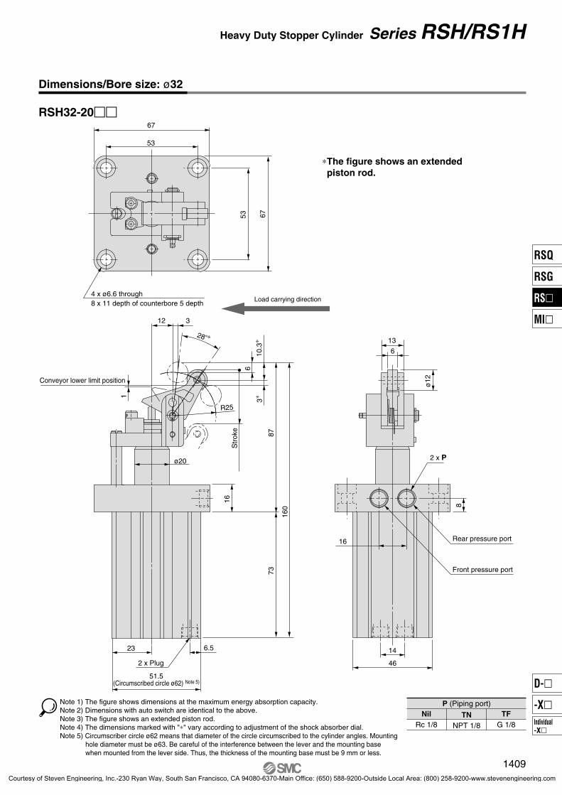
Dimensions/Bore size: ø32
RSH32-20��
Load carrying direction4 x ø6.6 through 8 x 11 depth of counterbore 5 depth
6753
∗The figure shows an extended piston rod.
P (Piping port)
TNNPT 1/8
NilRc 1/8
TFG 1/8
67
53
Note 1) The figure shows dimensions at the maximum energy absorption capacity.Note 2) Dimensions with auto switch are identical to the above.Note 3) The figure shows an extended piston rod.Note 4) The dimensions marked with "∗" vary according to adjustment of the shock absorber dial.Note 5) Circumscriber circle ø62 means that diameter of the circle circumscribed to the cylinder angles. Mounting
hole diameter must be ø63. Be careful of the interference between the lever and the mounting base when mounted from the lever side. Thus, the thickness of the mounting base must be 9 mm or less.
12 3
28 �∗
R25
10.3
∗6
3∗
Conveyor lower limit position
ø20
16
160
7387
2 x Plug
6.523
Str
oke
51.5(Circumscribed circle ø62) Note 5)
2 x P
16
13
6
ø12
8
14
46
Rear pressure port
Front pressure port
1409
Heavy Duty Stopper Cylinder Series RSH/RS1H
1
RSQ
RSG
RS�
MI�
Individual-X�
D-�
-X�
P1371-P1434-E.qxd 08.11.17 3:43 PM Page 1409
Courtesy of Steven Engineering, Inc.-230 Ryan Way, South San Francisco, CA 94080-6370-Main Office: (650) 588-9200-Outside Local Area: (800) 258-9200-www.stevenengineering.com

RS1H 63 -���50
80
GBE
GA
QA
LCZ
CT CT
øC
D
FZ
FX
Dimensions/Bore size: ø50, ø63, ø80
FZ
FX
B 93 99128
CD202025
CT81010
CZ364545
D324050
E647798
FT202525
FX 73 90110
FZ93 114138
GA162424
H128 144.5171.5
Width acrosscorners �
85103132
L455456
N 91113
O14 depth 518 depth 620 depth 6
QA10 12.512.5
QB 7 8.510
R404754
S21 24.531
T2 3.53
U5.56.46.7
V15.516 19.4
WB32 38.549
X556
Y10 10 12.5
θ�
242423
Stroke303040
A221 243.5299.5
Bore size (mm)
506380
Stroke303040
Bore size (mm)
506380
Model
RS1H50RS1H63RS1H80
P (Piping port)
TNNPT 1/8NPT 1/4NPT 1/4
NilRc 1/8Rc 1/4Rc 1/4
TFG 1/8G 1/4G 1/4
GB162435
W 72 87.5109
Note 1) The figure shows dimensions at the maximum energy absorption capacity.Note 2) The figure shows an extended piston rod.Note 3) Circumscriber circle ø� means that diameter of the circle circumscribed to the cylinder angles. Mounting hole diameter must be ø(�+1). Be careful of the interference
between the lever and the mounting base when mounted from the lever side. Thus, the thickness of the mounting base must be the values shown below or less.(RS1H50 : 10mm RS1H63 : 15mm RS1H80 : 18mm)
Load carrying directionS X
R
Conveyor lower limit position
T
Y VU
øD
FT
HB
A
QB2 x PlugWB
Str
oke
θ �
W(Circumscribed circle ø�) Note 3)
Series RSH/RS1H
4 x øN through8 x øO depth of counterbore
(mm)
Rear pressure port
Front pressure port
2 x P
1410
P1371-P1434-E.qxd 08.11.17 3:43 PM Page 1410
Courtesy of Steven Engineering, Inc.-230 Ryan Way, South San Francisco, CA 94080-6370-Main Office: (650) 588-9200-Outside Local Area: (800) 258-9200-www.stevenengineering.com
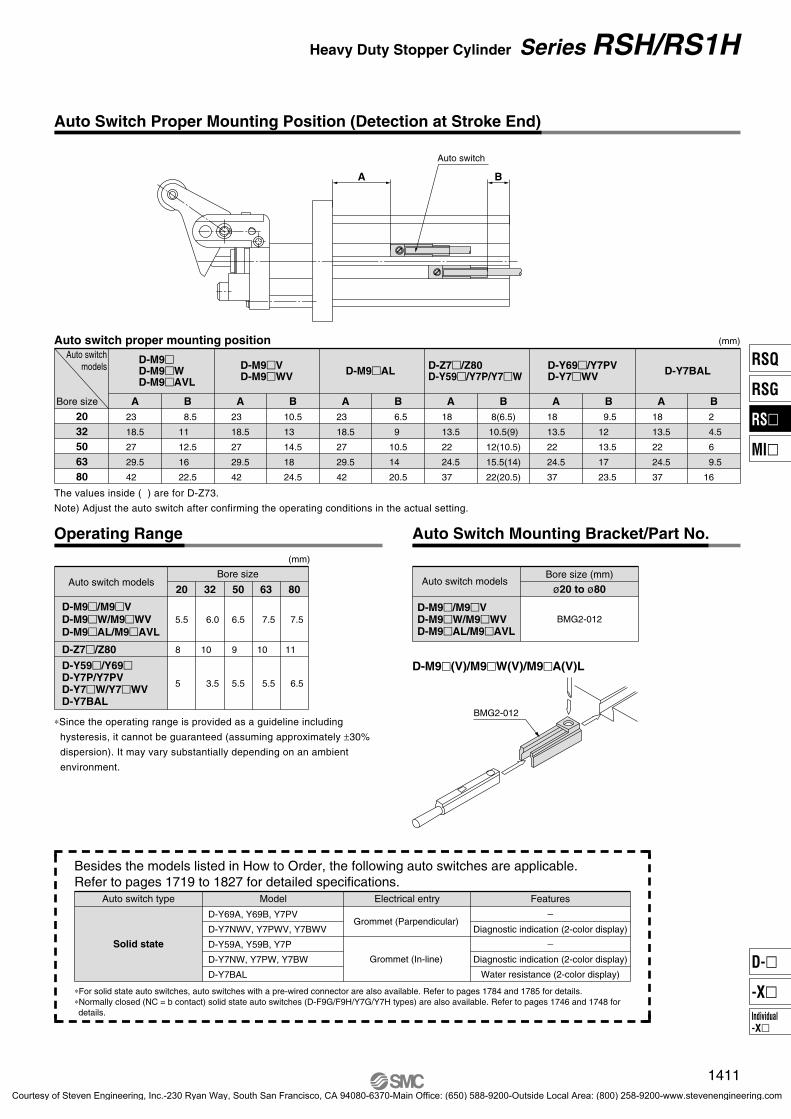
Auto switch modelsBore size
5.5
8
5
6.0
10
3.5
20
6.5
9
5.5
32 50
7.5
10
5.5
7.5
11
6.5
63 80
D-Z7�/Z80
D-M9�/M9�VD-M9�W/M9�WVD-M9�AL/M9�AVL
(mm)
Operating Range
D-Y59�/Y69�D-Y7P/Y7PVD-Y7�W/Y7�WVD-Y7BAL
Auto Switch Mounting Bracket/Part No.
Bore size (mm) Auto switch models
BMG2-012D-M9�/M9�VD-M9�W/M9�WVD-M9�AL/M9�AVL
ø20 to ø80
∗For solid state auto switches, auto switches with a pre-wired connector are also available. Refer to pages 1784 and 1785 for details.∗Normally closed (NC = b contact) solid state auto switches (D-F9G/F9H/Y7G/Y7H types) are also available. Refer to pages 1746 and 1748 for details.
Auto switch type Model FeaturesElectrical entry
D-Y69A, Y69B, Y7PV
D-Y7NWV, Y7PWV, Y7BWV
D-Y59A, Y59B, Y7P
D-Y7NW, Y7PW, Y7BW
D-Y7BAL
�
Diagnostic indication (2-color display)
�
Diagnostic indication (2-color display)
Water resistance (2-color display)
Grommet (Parpendicular)
Grommet (In-line)
Besides the models listed in How to Order, the following auto switches are applicable.Refer to pages 1719 to 1827 for detailed specifications.
Solid state
Auto switch proper mounting position
Bore size
Auto switchmodels
D-M9�D-M9�WD-M9�AVL
D-M9�VD-M9�WV D-M9�AL
23
18.5
27
29.5
42
2032506380
A 8.5
11
12.5
16
22.5
B23
18.5
27
29.5
42
A10.5
13
14.5
18
24.5
B23
18.5
27
29.5
42
A 6.5
9
10.5
14
20.5
B
D-Z7�/Z80D-Y59�/Y7P/Y7�W
18
13.5
22
24.5
37
A8(6.5)
10.5(9)
12(10.5)
15.5(14)
22(20.5)
B
D-Y69�/Y7PVD-Y7�WV
18
13.5
22
24.5
37
A 9.5
12
13.5
17
23.5
B
(mm)
Auto Switch Proper Mounting Position (Detection at Stroke End)
BA
Auto switch
D-Y7BAL
18
13.5
22
24.5
37
A 2
4.5
6
9.5
16
B
The values inside ( ) are for D-Z73.
Note) Adjust the auto switch after confirming the operating conditions in the actual setting.
D-M9�(V)/M9�W(V)/M9�A(V)L
∗Since the operating range is provided as a guideline including
hysteresis, it cannot be guaranteed (assuming approximately ±30%
dispersion). It may vary substantially depending on an ambient
environment.
BMG2-012
1411
Heavy Duty Stopper Cylinder Series RSH/RS1H
RSQ
RSG
RS�
MI�
Individual-X�
D-�
-X�
P1371-P1434-E.qxd 08.11.17 3:43 PM Page 1411
Courtesy of Steven Engineering, Inc.-230 Ryan Way, South San Francisco, CA 94080-6370-Main Office: (650) 588-9200-Outside Local Area: (800) 258-9200-www.stevenengineering.com
Lever Detection Switch (Proximity Switch)
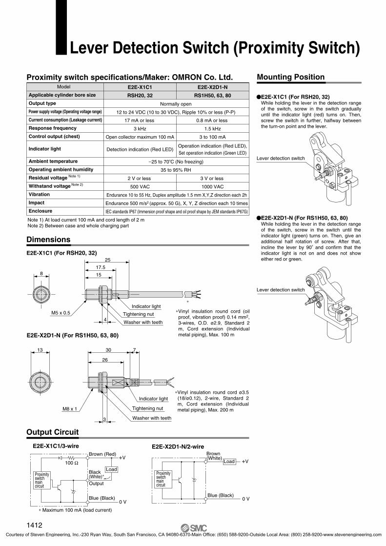
Proximity switch specifications/Maker: OMRON Co. Ltd.
Note 1) At load current 100 mA and cord length of 2 mNote 2) Between case and whole charging part
E2E-X1C1/3-wire E2E-X2D1-N/2-wire
E2E-X1C1 (For RSH20, 32)
E2E-X2D1-N (For RS1H50, 63, 80)
Load
E2E-X1C1 (For RSH20, 32)While holding the lever in the detection range of the switch, screw in the switch gradually until the indicator light (red) turns on. Then, screw the switch in further, halfway between the turn-on point and the lever.
E2E-X2D1-N (For RS1H50, 63, 80)While holding the lever in the detection range of the switch, screw in the switch until the indicator light (green) turns on. Then, give an additional half rotation of screw. After that, incline the lever by 90� and confirm that the indicator light is not on and does not show either red or green.
Mounting Position
Dimensions
Output Circuit
Model
Applicable cylinder bore size
Output type
Power supply voltage (Operating voltage range)
Current consumption (Leakage current)
Response frequency
Control output (chest)
Indicator light
Ambient temperature
Operating ambient humidity
Residual voltage
Withstand voltage
Vibration
Impact
Enclosure
Note 1)
Note 2)
E2E-X1C1
RSH20, 32
17 mA or less
3 kHz
Open collector maximum 100 mA
Detection indication (Red LED)
2 V or less
500 VAC
E2E-X2D1-N
RS1H50, 63, 80
0.8 mA or less
1.5 kHz
3 to 100 mA
Operation indication (Red LED),Set operation indication (Green LED)
3 V or less
1000 VAC
Normally open
12 to 24 VDC (10 to 30 VDC), Ripple 10% or less (P-P)
�25 to 70�C (No freezing)
35 to 95% RH
Endurance 10 to 55 Hz, Duplex amplitude 1.5 mm X,Y,Z direction each 2h
Endurance 500 m/s2 (approx. 50 G), X, Y, Z direction each 10 times
IEC standards IP67 (Immersion proof shape and oil proof shape by JEM standards IP67G)
100 Ω
Brown (Red)
Black (White)∗
Blue (Black)
Output
Proximityswitchmain circuit
∗ Maximum 100 mA (load current)
+V
0 V
Brown (White)
Blue (Black)
Proximityswitchmain circuit
+V
0 V
Load
Tightening nut
Washer with teeth
∗Vinyl insulation round cord ø3.5 (18/ø0.12), 2-wire, Standard 2 m, Cord extension (Individual metal piping), Max. 200 m
13
3
730
26
M8 x 1
Indicator light
8
25
17.5
15
Indicator light
Tightening nut
Washer with teeth4M5 x 0.5
∗
∗Vinyl insulation round cord (oil proof, vibration proof) 0.14 mm2, 3-wires, O.D. ø2.9, Standard 2 m, Cord extension (Individual metal piping), Max. 100 m
Lever detection switch
Lever detection switch
1412
P1371-P1434-E.qxd 08.11.17 3:43 PM Page 1412
Courtesy of Steven Engineering, Inc.-230 Ryan Way, South San Francisco, CA 94080-6370-Main Office: (650) 588-9200-Outside Local Area: (800) 258-9200-www.stevenengineering.com

CautionInstructions Selection
Danger
Caution
Mounting
Caution
Operation
Caution
1. Shock absorber capacity variable adjust-ment method (ø50 to ø80)To stop the work gently, loosen the fixing screw (M4) on the stopper and turn the shock absorber dial according to the energy value of the transferred object to select the optimum absorption position (retardation value). After adjustment, tighten the fixing screw firmly to secure the shock absorber dial.Note 1) Cautions for adjustment When adjusting the shock absorber retardation value, first try the maximum value and then proceed to smaller values. If the energy value of the transferred work piece is larger than the retardation value of the shock absorber, an excessive load will be applied to the lever and may cause damage.Note 2) Although it is not possible to change the shock absorber drag value of ø20 and ø32 types, the shock absorber stroke can be changed by adjusting the height of the adjustment dial (6st to 4st.)Note 3) Please consult SMC if shock absorption is not soft, even after adjusting the shock absorber with the above method.
2. How to change the positional relationship between the transfer and piping directionsThe positional relationship between the transfer and piping directions can be changed in 90� increments (or 180� increments in case of ø20).
3. How to replace shock absorber during maintenanceLoosen the hexagon socket head bolts and shock absorber fixing screw (M4) on the stopper to remove the stopper from the lever holder. Incline the lever by 90� and pull out the shock absorber. (In case of ø20 and ø32, remove the stopper, loosen the adjustment dial and then pull out the shock absorber.)∗Cautions for assemblyAfter replacing the shock absorber, tighten the bolts and fixing screw firmly and apply grease to the shock absorber rod end surface.
�ø20Loosen the fixing screw (M3) be-side the rod cover and pull up the guide rod. The lever is released to allow 180� rotations.
�ø32 to ø80Fit a driver (-) into the notch on the guide rod end surface and loosen the guide rod. The lever is released to allow rotations in 90� increments.
1. Do not collide the pallet while the lever is standing erect.In case of a lever with built-in shock absorber type, do not collide the next pallet while the lever is standing erect. Otherwise, all energy will be applied to the cylinder body.
2. When a load directly connected to the cylin-der is stopped at an intermediate position:Apply the operating range in the catalog only in these cases where the stopper cylinder is used to stop pallets on a conveyor belt. When using the stopper cylinder to stop loads directly connected to a cylinder or some other equipment, a lateral load is applied as the cylinder thrust. Consult SMC in such cases.
1. Use the equipment only within the specified operating range.If the condition exceeds the specified operating range, it will cause excessive impact or vibration to the stopper cylinder, leading to possible damages.
1. Do not apply rotational torque to the cylin-der rod.Align the cylinder parallel to the working face of the pallet working when installing in order to prevent rotational torque working on the cylinder rod.
2. Do not scratch or gouge the sliding part of the piston rod or guide rod.Scratches and gouges may damage the packing, causing air leakage or malfunction.
1. In case of cylinders with locking mechanism, do not apply an external force from the opposite side when the lever is locked.Lower the cylinder before adjusting the conveyor or moving the pallet.
2. In case of cylinders with locking mechanism, do not collide the pallet and roller when the lever is locked.If the pallet collides with the roller in the locked state, it may cause lever malfunction. (The lever is released when the cylinder is fully retracted.)
3. Do not let your hand become caught when operating the cylinder.The lever holder goes up and down while the cylinder is in operation. Pay sufficient attention not to let your hand or fingers become caught between the rod cover and lever holder.
4. Do not let water, cutting oil or dust splash on the equipment.It can cause oil leakage and malfunction of the shock absorber.
Series RSH/RS1HSpecific Product PrecautionsBe sure to read before handling. Refer to front matters 42 and 43 for Safety Instructions and pages 3 to 11 for Actuator and Auto Switch Precautions.
Set screw (M4)
Stopper
Adjustmentdial
Shockabsorber
Stopper
Lever
Set screw (M4)
ø50 to ø80ø20, ø32
LeverShockabsorber
Set screw (M4)
Stopper
Adjustmentdial
ø20
Guide rod
Set screw (M3)
ø32, ø50, ø63, ø80
1413
RSQ
RSG
RS�
MI�
Individual-X�
D-�
-X�
337-RSH-RS1H.qxd 10.12.27 1:28 PM Page 1
Courtesy of Steven Engineering, Inc.-230 Ryan Way, South San Francisco, CA 94080-6370-Main Office: (650) 588-9200-Outside Local Area: (800) 258-9200-www.stevenengineering.com