smb and smc connectors€“32 threaded coupling, and have a higher upper frequency limit than smb....
TRANSCRIPT

(978) 927-1060 • FAX (978) 922-6430 • www.DeltaRF.comP.O. Box 53 • 416 Cabot St. • Beverly, MA 01915
SMB and SMC Connectors
ContentsCLICK ON ANY LINE TO GO DIRECTLY TO THE INDICATED PAGE
Navigation Guide . . . . . . . . . . . . . . . . . . . . . . . . . . . . . . . . . . . . . . . . . . . . 2
Specifications and interface dimensions . . . . . . . . . . . . . . . . . . . . . . . . . . . 3
ONLINE CATALOG
Technical InformationMounting Figures . . . . . . . . . . . . . . . . . . . . . . . . . . . . . . . . . . . . . . . . . . . . . . . . 9Cable Groups. . . . . . . . . . . . . . . . . . . . . . . . . . . . . . . . . . . . . . . . . . . . . . . . . . . 10Cable Assembly Instructions . . . . . . . . . . . . . . . . . . . . . . . . . . . . . . . . . . . . . . . 11Assembly Tooling . . . . . . . . . . . . . . . . . . . . . . . . . . . . . . . . . . . . . . . . . . . . . . . 11Ordering and Warranty . . . . . . . . . . . . . . . . . . . . . . . . . . . . . . . . . . . . . . . . . . . 12
SMB Cable ConnectorsStraight Cable Plugs . . . . . . . . . . . . 4Right Angle Cable Plugs . . . . . . . . . 4Bulkhead Mounted Cable Jacks . . . . 4
SMB ReceptaclesBulkhead Jack Receptacles . . . . . . . . 5Panel Jack Receptacles. . . . . . . . . . . 5P.C. Board Receptacles . . . . . . . . . . 6PressMount Receptacles . . . . . . . . . 6
SMC Cable ConnectorsStraight Cable Plugs . . . . . . . . . . . . 7Right Angle Cable Plugs . . . . . . . . . 7Bulkhead Mounted Cable Jacks . . . . 7
SMC ReceptaclesBulkhead Jack Receptacles . . . . . . . . 8Panel Jack Receptacles. . . . . . . . . . . 8P.C. Board Receptacles . . . . . . . . . . 8
Connect Here.Connect Here.

DELTA ELECTRONICS MANUFACTURING
(978) 927-1060 • FAX (978) 922-6430 • www.deltarf.com 2
Online Catalog Navigation Guide
We have configured this online catalog to take advantage of Acrobat navigation shortcuts (links).However, these links are not visible on the pages— making them visible would compromise thepage’s readability.• Clicking on any entry in the Table of Contents will take you to the indicated page.• Shown below are the “hot spots” on all of the product pages that will take you to background
information on various connector characteristics.• After you use a link to jump to another page, you can use the “back” arrow in Acrobat’s menu bar
to return to the page you jumped from.• Configure Acrobat Reader to show bookmarks for a table of contents by specific characteristic
(for example, cable plugs broken out by cable attachment method).• To find a specific part number, use Acrobat’s search feature.In addition, the pages are formatted to fit within the margins of standard laser or inkjet printers—no need to use the “shrink to fit” option when printing pages from Acrobat.
Click here to go to the Table of Contents
Panel Jack—Military Clamp for Flexible Cable
CableFig.
Dimensions Mounting PlatingDelta P/NGroup A B C Figure Body Contact
1 1 1.75 .63 .75 33 Nickel Silver 1011-001-N330 A/202, 3 1 1.75 .63 .75 33 Nickel Silver 1011-004-N330 A/205, 6 2 1.16 .55 .50 07 Nickel Silver UG-291C/U A/17
Figure 1 Figure 2
C dia.
AB
AB
C dia.
AssemblyProcedure/Trim Code
Click here to jump to a guide to Delta cable groups.
Click here to jump to dimensionsfor Delta mounting figures.
Click here to jump to the cable assembly procedure for this connector.
DELTA ELECTRONICS MANUFACTURINGBNC Cable Jacks
Click on the Delta logo on any pageto jump to the table of contents. Click on the page title to jump to specifications
and interface dimensions.
Click here to go to Delta’s website if your computer is configured for Web connection via Acrobat.

DELTA ELECTRONICS MANUFACTURING
(978) 927-1060 • FAX (978) 922-6430 • www.deltarf.com 3
SMB and SMC Connectors
General DescriptionDelta SMB connectors are subminiature, 50Ω impedance connectors with snap-on coupling.They are best suited for use with cables in the range of .070" to .120" diameter, such as RG-178 and RG-316/U.Delta SMC connectors (page 7) are similar in size and construction to SMB series, but employ#10–32 threaded coupling, and have a higher upper frequency limit than SMB.All Delta SMB and SMC connectors are available with gold-plated bodies, or with nickel-platedbodies for economy.As with our other connector series, Delta’s customer-driven design results in SMB and SMC series connectors with practical and unique features that make your design and assemblyprocess easier. Some of these include:• SMB PressMount receptacles (page 6) mount securely in a single round hole, saving space on
your components and reducing your housing fabrication costs.• SMB and SMC panel receptacles with flange sizes to match the same hole pattern as
standard SMA connectors, letting you drill one hole pattern and mount SMB, SMC, BNC, N, SMA, or TNC series connectors as needed.
Our SMB and SMC series product line is still growing, so call if you don’t see what you need.For adapters between SMB or SMC and other series, download the documentDeltaABS.pdf from our website.
Electrical:Nominal Impedance: 50 ohms.Frequency Range: SMB: DC–4 GHz.
SMC: DC–10 GHz.Voltage Rating: 250 volts RMS (when used with RG-178-
class cables); 335 volts RMS (when usedwith RG-316-class cables).
Dielectric WithstandingVoltage: 750 volts RMS (when used with RG-178-class
cables); 1,000 volts RMS (when used with RG-316-class cables).
Insulation Resistance: 1,000 megohms.
Materials/Finishes:Insulators: Teflon per ASTM D1710.Male Contacts: Brass per ASTM B16.Female Contacts: Beryllium Copper per ASTM B196.
Contact Plating: Gold per MIL-G-45204.Gaskets: Silicone rubber per ZZ-R-765, Class II,
Grade 50.Other Metal Parts: Brass per ASTM B16, plated:
Gold per MIL-G-45208, orNickel per QQ-N-290.
All other specifications are in accordance with thelatest issues of MIL-PRF-39012, or MIL-A-55339, orother applicable MIL specifications, and interfacesare in accordance with MIL-STD-348.
*These specifications are typical and may not apply to all connectors. Detailed specifications forindividual connectors are available on request.
SMB and SMC Specifications*
.064 max.
.007/.037
.081 max.
.007min.
.141 min.
Reference Plane
Plug
ReferencePlane
.019/.021
.146 max.
.082 min.
.065 min.
.000 min.
.131/.141
.052 min..117 max.
.007 max.
Jack
**Some proportions altered to illustrate detail.
SMB Interfaces**
.147 min.
.081 max.
.233 max.
.134 max..122 max.
Reference Plane
.190-32 UNEF-2B;
.110 min. thread length
Plug
.019/.021
.146 max.
.082 min.
.000 min.
.024 min..084 max..134 min.
.234 min.
.190-32 UNEF-2A; min. 2 complete threads
.123/.133
Reference PlaneJack
SMC Interfaces**
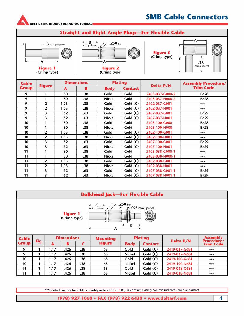
Straight and Right Angle Plugs—For Flexible Cable
CableFigure
Dimensions PlatingDelta P/N
Assembly Procedure/Group A B Body Contact Trim Code
9 1 .80 .38 Gold Gold 2403-037-G000-2 B/289 1 .80 .38 Nickel Gold 2403-037-N000-2 B/289 2 1.03 .38 Gold Gold (C) 2402-037-G001 ***9 2 1.03 .38 Nickel Gold (C) 2402-037-N001 ***9 3 .52 .63 Gold Gold (C) 2407-037-G001 B/299 3 .52 .63 Nickel Gold (C) 2407-037-N001 B/29
10 1 .80 .38 Gold Gold 2403-100-G000 B/2810 1 .80 .38 Nickel Gold 2403-100-N000 B/2810 2 1.03 .38 Gold Gold (C) 2402-100-G001 ***10 2 1.03 .38 Nickel Gold (C) 2402-100-N001 ***10 3 .52 .63 Gold Gold (C) 2407-100-G001 B/2910 3 .52 .63 Nickel Gold (C) 2407-100-N001 B/2911 1 .80 .38 Gold Gold 2403-038-G000-1 ***11 1 .80 .38 Nickel Gold 2403-038-N000-1 ***11 2 1.03 .38 Gold Gold (C) 2402-038-G001 ***11 2 1.03 .38 Nickel Gold (C) 2402-038-N001 ***11 3 .52 .63 Gold Gold (C) 2407-038-G001-1 B/2911 3 .52 .63 Nickel Gold (C) 2407-038-N001-1 B/29
Figure 1(Crimp type)
A
B (crimp sleeve)
Figure 2(Crimp type)
A
B(crimp sleeve) .250 hex
Figure 3(Crimp type)
A
B.38
(crimp sleeve)
Bulkhead Jack—For Flexible Cable
Figure 1(Crimp type)
AB
.093 max. panelC
(crimp sleeve).250 hex
CableFig.
Dimensions Mounting PlatingDelta P/NGroup A B C Figure Body Contact
9 1 1.17 .426 .38 68 Gold Gold (C) 2419-037-G681 ***9 1 1.17 .426 .38 68 Nickel Gold (C) 2419-037-N681 ***10 1 1.17 .426 .38 68 Gold Gold (C) 2419-100-G681 ***10 1 1.17 .426 .38 68 Nickel Gold (C) 2419-100-N681 ***11 1 1.17 .426 .38 68 Gold Gold (C) 2419-038-G681 ***11 1 1.17 .426 .38 68 Nickel Gold (C) 2419-038-N681 ***
AssemblyProcedure/Trim Code
DELTA ELECTRONICS MANUFACTURING
(978) 927-1060 • FAX (978) 922-6430 • www.deltarf.com 4
SMB Cable Connectors
***Contact factory for cable assembly instructions. • (C) in contact plating column indicates captive contact.

Bulkhead Jack Receptacles
Figure 1
Figure 2
AB
C (I.D.)
.250 hex
.093 max. panel
C (I.D.)
.312 hex
.093 max. panel
A
.38B
FigureDimensions Mounting Plating
Delta P/NA B C Figure Body Contact
1 .59 .265 .035 68 Gold Gold (C) 2420-000-G6811 .59 .265 .035 68 Nickel Gold (C) 2420-000-N6812 .59 .75 .022 68 Gold Gold (C) 2422-000-G6812 .59 .75 .022 68 Nickel Gold (C) 2422-000-N681
Panel Jack Receptacle
Figure 1(3/8" square flange)
Figure 2(1/2" square flange)
.58
.375Asquare
Cdia. typ.
.065.025 (I.D.)
B (L) typ.C
.58
.375Asquare
Cdia. typ.
.065.025 (I.D.)
B(L) typ.C
FigureDimensions Mounting Plating
Delta P/NA B C Figure Body Contact
1 .375 .232 .093 91A Gold Gold (C) 2413-000-G9111 .375 .232 .093 91A Nickel Gold (C) 2413-000-N9112 .500 .340 .102 05 Gold Gold (C) 2413-000-G0512 .500 .340 .102 05 Nickel Gold (C) 2413-000-N051
DELTA ELECTRONICS MANUFACTURING
(978) 927-1060 • FAX (978) 922-6430 • www.deltarf.com 5
SMB Receptacles
(C) in contact plating column indicates captive contact.

FigureDimensions Max. Mounting Plating
Delta P/NA B C Board Figure Body Contact
1 .300 .060 .155 .100 PCB06 Gold Gold (C) 2468-000-G0011 .300 .060 .155 .100 PCB06 Nickel Gold (C) 2468-000-N0012 .59 .375 .155 .100 PCB06 Gold Gold (C) 2470-000-G00E2 .59 .375 .155 .100 PCB06 Nickel Gold (C) 2470-000-N00E
Printed-Circuit Board Receptacles
Figure 1 Figure 2
AB
C.038 dia.
.312 hex
.040 sq. typ. .200 typ.
A
BC
.038 dia..312
hex
.040 sq. typ.
.200 typ.
PressMount Receptacles
FigureDimensions Min. Mounting Plating
Delta P/NA B Panel Hole Body Contact
1 .062 .050 .100 .267 ±.001 dia. Passivated Gold (C) 2420-000-K911-12 .500 .060 .062 .182 ±.001 dia. Gold Gold (C) 2421-000-G911
Figure 1(Post contact, front mount,
stainless steel body)
.265.115
A
B dia.
.300 dia.
.270dia. over knurl
Delta PressMount ReceptaclesComponent housing
InternalCircuitry
Component housing
InternalCircuitry
These connectors eliminate the need for complicatedmounting hole patterns and mounting hardware.
They are simply pressed into a single through hole, and the precisely-engineered knurled mounting sectionprovides retention strength far greater than normalmating and unmating forces. An integral shoulder provides a positive stop when mounting.
PressMounts are available for a wide variety of Deltaconnector series, and can be used in packages as smallas the outer diameter of the connector body.
Figure 2(Post contact, rear mount,
brass body)
.240.070
A
B dia.
.275 dia..060.062
.030.100
.186dia. over knurl
.195 dia.
.115 dia.
Front mount Rear mount
DELTA ELECTRONICS MANUFACTURING
(978) 927-1060 • FAX (978) 922-6430 • www.deltarf.com 6
SMB Receptacles
(C) in contact plating column indicates captive contact.

Straight and Right Angle Plugs—For Flexible Cable
CableFigure
Dimensions PlatingDelta P/N
Assembly Procedure/Group A B Body Contact Trim Code
9 1 .80 .38 Gold Gold 2503-037-G000 B/289 1 .80 .38 Nickel Gold 2503-037-N000 B/289 2 1.03 .38 Gold Gold (C) 2502-045-G001-1 ***9 2 1.03 .38 Nickel Gold (C) 2502-045-N001-1 ***9 3 .56 .63 Gold Gold (C) 2507-037-G001 B/299 3 .56 .63 Nickel Gold (C) 2507-037-N001 B/29
10 1 .80 .38 Gold Gold 2503-100-G000 B/2810 1 .80 .38 Nickel Gold 2503-100-N000 B/2810 2 1.03 .38 Gold Gold (C) 2502-100-G000-1 ***10 2 1.03 .38 Nickel Gold (C) 2502-100-N000-1 ***10 3 .56 .63 Gold Gold (C) 2507-100-G001 B/2910 3 .56 .63 Nickel Gold (C) 2507-100-N001 B/2911 1 .80 .38 Gold Gold 2503-038-G000 B/2811 1 .80 .38 Nickel Gold 2503-038-N000 B/2811 2 1.03 .38 Gold Gold (C) 2502-038-G001-1 ***11 2 1.03 .38 Nickel Gold (C) 2502-038-N001-1 ***11 3 .56 .63 Gold Gold (C) 2507-038-G001 B/2911 3 .56 .63 Nickel Gold (C) 2507-038-N001 B/29
Figure 1(Crimp type)
A
B(crimp sleeve)
.250 hex
Figure 2(Crimp type)
A
B(crimp sleeve)
.250 hex.234 hex
Figure 3(Crimp type)
.234 hex
A
B.38
(crimp sleeve)
Bulkhead Jack—For Flexible Cable
Figure 1(Crimp type)
AB
.093 max. panelC
(crimp sleeve).250 hex
CableFig.
Dimensions Mounting PlatingDelta P/NGroup A B C Figure Body Contact
9 1 1.17 .426 .38 68 Gold Gold (C) 2519-037-G681 ***9 1 1.17 .426 .38 68 Nickel Gold (C) 2519-037-N681 ***10 1 1.17 .426 .38 68 Gold Gold (C) 2519-100-G681 ***10 1 1.17 .426 .38 68 Nickel Gold (C) 2519-100-N681 ***11 1 1.17 .426 .38 68 Gold Gold (C) 2519-038-G681 ***11 1 1.17 .426 .38 68 Nickel Gold (C) 2519-038-N681 ***
AssemblyProcedure/Trim Code
DELTA ELECTRONICS MANUFACTURING
(978) 927-1060 • FAX (978) 922-6430 • www.deltarf.com 7
SMC Cable Connectors
***Contact factory for cable assembly instructions. • (C) in contact plating column indicates captive contact.

Bulkhead Jack Receptacles
Figure 1
Figure 2
AB
C (I.D.)
.250 hex
.093 max. panel
C (I.D.)
.312 hex
.093 max. panel
A
.38B
FigureDimensions Mounting Plating
Delta P/NA B C Figure Body Contact
1 .59 .265 .035 68 Gold Gold (C) 2520-000-G6811 .59 .265 .035 68 Nickel Gold (C) 2520-000-N6812 .59 .75 .022 68 Gold Gold (C) 2522-000-G6812 .59 .75 .022 68 Nickel Gold (C) 2522-000-N681
Panel Jack Receptacle
Figure 1(3/8" square flange)
Figure 2(1/2" square flange)
.58
.375Asquare
Cdia. typ.
.065.025 (I.D.)
B (L) typ.C
.58
.375Asquare
Cdia. typ.
.065.025 (I.D.)
B(L) typ.C
FigureDimensions Mounting Plating
Delta P/NA B C Figure Body Contact
1 .375 .232 .093 91A Gold Gold (C) 2513-000-G9111 .375 .232 .093 91A Nickel Gold (C) 2513-000-N9112 .500 .340 .102 05 Gold Gold (C) 2513-000-G0512 .500 .340 .102 05 Nickel Gold (C) 2513-000-N051
Printed-Circuit Board Receptacles
Figure 1 Figure 2
AB
C.038 dia.
.312 hex
.040 sq. typ. .200 typ.
A
BC
.038 dia..312
hex
.040 sq. typ.
.200 typ.
FigureDimensions Max. Mounting Plating
Delta P/NA B C Board Figure Body Contact
1 .300 .060 .155 .100 PCB06 Gold Gold (C) 2568-000-G0011 .300 .060 .155 .100 PCB06 Nickel Gold (C) 2568-000-N0012 .59 .375 .155 .100 PCB06 Gold Gold (C) 2570-000-G00E2 .59 .375 .155 .100 PCB06 Nickel Gold (C) 2570-000-N00E
DELTA ELECTRONICS MANUFACTURING
(978) 927-1060 • FAX (978) 922-6430 • www.deltarf.com 8
SMC Receptacles
(C) in contact plating column indicates captive contact.
DELTA ELECTRONICS MANUFACTURING
(978) 927-1060 • FAX (978) 922-6430 • www.deltarf.com 9
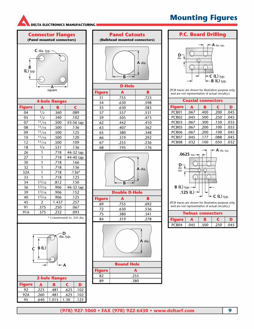
Mounting Figures
Connector Flanges(Panel mounted connectors)
4-hole flangesFigure A B C
04 1/2 .360 .08905 1/2 .340 .10207 11/16 .500 #3-56 tap08 11/16 .500 .13609 11/16 .500 .12510 11/16 .500 .12012 11/16 .500 .10918 3/4 .531 .13626 1 .718 #6-32 tap27 1 .718 #4-40 tap30 1 .718 .16632 1 .718 .136
32A 1 .718 .136*33 1 .718 .12534 13/32 .812 .15036 13/16 .906 #6-32 tap39 13/16 .906 .15240 13/16 .906 .12545 2 1.437 .25791 .375 .250 .067
91A .375 .232 .093
Asquare
C dia. typ.
B(L) typ.C
A
D dia. typ.
B (L)CC
* Countersunk to .245 dia.
2-hole flanges
Figure A B C D92 .223 .481 .625 .102
92A .260 .481 .625 .10295 .640 1.015 1.30 .125
Panel Cutouts(Bulkhead mounted connectors)
D-Hole
Figure A B51 .755 .72354 .630 .59855 .630 .58357 .557 .53159 .505 .47362 .442 .41063 .407 .36265 .380 .34866 .319 .29267 .255 .23668 .195 .176
Double D-Hole
Figure A B69 .755 .69272 .630 .53675 .380 .34184 .319 .278
B
A dia.
B
A dia.
Round Hole
Figure A82 .25589 .380
A dia.
P.C. Board Drilling
Twinax connectors
Figure A B C DPCB04 .045 .500 .250 .045
A dia. typ.
Ddia.
B (L) typ.CC (L) typ.C
A dia. typ.
.0625 typ.
Ddia.typ.
B (L) typ.C
C (L) typ.C.125 (L)C
Coaxial connectors
Figure A B C DPCB01 .067 .400 .200 .045PCB02 .045 .500 .250 .045PCB03 .067 .300 .150 .035PCB05 .067 .200 .100 .055PCB06 .067 .200 .100 .045PCB07 .045 .177 .088 .045PCB08 .032 .100 .050 .032
(PCB traces are shown for illustrative purpose only,and are not representative of actual circuitry.)
(PCB traces are shown for illustrative purpose only,and are not representative of actual circuitry.)

DELTA ELECTRONICS MANUFACTURING
(978) 927-1060 • FAX (978) 922-6430 • www.deltarf.com 10
Cable Groups
Delta Cable Groups
Group Cables
1A RG-5, 5A, 5B, 21, 21A; M17/73, /162
1 1B RG-6, 6A; M17/2
1C RG-143, 143A, 212, 222; M17/73, /112, /162
22A RG-8, 8A, 213; M17/74
2B RG-11, 11A; M17/6
3A RG-9, 9A, 9B, 214; M17/75
3 3B RG-13A, 216; M17/77
3C RG-225; M17/127
4 RG-393; M17/127
5 RG-58, 58A, 58C, 141, 141A; M17/28, /111
66A RG-55A, 142, 142A, 223, 400; M17/60, /84, /128
6B RG-55, 55B, 142B; M17/60, /84
77A RG-59, 59A, 59B, 62, 62A, 62B, 62C, 210; M17/29, /30, /97
7B RG-71, 71A, 71B; M17/90
88A RG-122; M17/54
8B RG-180, 180A, 180B, 195; M17/95, /137
99A RG-174, 188, 188A, 316; M17/152
9B RG-179A, 179B, 187, 187A; M17/94, /136
10 Double-Shielded RG-174, 316; M17/152
11 RG-178, 178A, 178B, 196, 196A; M17/93
12 .250" semi-rigid; RG-401; M17/129
13 .141" semi-rigid; RG-402; M17/130
14 .085" semi-rigid; RG-405; M17/133
15 RG-10, 12, 215; M17/6, /74
16 RG-14A, 217; M17/78, /165
17 RG-17A, 218
18 RG-18A, 219
19 RG-115A
20 RG-118A, 228A
21 RG-126
22 RG-302
23 RG-303
24 RG-304
25 Special 8X cable; contact factory for details.
26 Belden 8281
27 RG-108, 108A; M17/45
28 RG-22, 22A, 22B; M17/15
29 Belden 9207; Dearborn 6207; IBM 7362211
30 M17/176
31 AT&T 735A
RG-5, 5A, B 1ARG-6, 6A 1BRG-8, 8A 2ARG-9, 9A, B 3ARG-10 15RG-11, 11A 2BRG-12 15RG-13A 3BRG-14A 16RG-17A 17RG-18A 18RG-21, 21A 1ARG-22, 22A, B 28RG-55, 55B 6BRG-55A 6ARG-58, 58A, C 5RG-59, 59A, B 7ARG-62, 62A, B, C 7ARG-71, 71A, B 7BRG-108, 108A 27RG-115A 19RG-118A 20RG-122 8ARG-126 21RG-141, 141A 5RG-142, 142A 6ARG-142B 6BRG-143, 143A 1CRG-174 9ARG-174DS 10RG-178, 178A, B 11RG-179A, 179B 9BRG-180, 180A, B 8BRG-187, 187A 9BRG-188, 188A 9ARG-195 8BRG-196, 196A 11RG-210 7ARG-212 1CRG-213 2ARG-214 3ARG-215 15RG-217 16RG-218 17RG-219 18RG-222 1CRG-223 6A
RG-225 3CRG-228A 20RG-302 22RG-303 23RG-304 24RG-316 9ARG-316DS 10RG-393 4RG-400 6ARG-401 12RG-402 13RG-405 14M17/2 1BM17/6 2BM17/15 28M17/28 5M17/29 7AM17/30 7AM17/45 27M17/73 1AM17/162 1AM17/112 1CM17/74 2AM17/75 3AM17/127 3CM17/77 3BM17/60 6AM18/84 6AM17/128 6AM17/97 7AM17/54 8AM17/95 8BM17/137 8BM17/152 9AM17/93 11M17/129 12M17/130 13M17/133 14M17/78 16M17/165 16M17/176 30AT&T 735A 31Belden 8281 26Belden 9207 29Dearborn 6207 29IBM 7362211 29
Cable Group FinderCable Group Cable Group

DELTA ELECTRONICS MANUFACTURING
(978) 927-1060 • FAX (978) 922-6430 • www.deltarf.com 11
Assembly Procedures
Frame only—P/N M22520/5-01—Use with interchangeable dies listed below.
For Cable Group(s) Hex Die Size Die Set P/N Closure
2, 3, 4 .429 hex, .400 wide M22520/5-61 A
5, 6 .213 hex, .400 wide M22520/5-19 B
7 .255 hex, .400 wide M22520/5-19 A
9 .128 hex, .400 wide M22520/5-35 B
10 .151 hex, .400 wide M22520/5-37 B
11 .105 hex, .400 wide M22520/5-33 B
M22520/5-01
Crimp Tools for Flexible Cable
Assembly Procedure B
Crimp Sleeve Contact (captive)
Contact(non-captive)
Solder
A
or
B C
1) Trim cable per chart. Slide crimpsleeve back onto cable.
2) If support insulator is provided for RG-62 or 71cable, insert into hollow in dielectric. Solder con-tact onto center conductor; back of contact flushwith trimmed end of cable dielectric (omit this stepfor right angle connectors with access caps). Flarecut end of braid slightly by rotating dielectric.
3) Insert cable/contact into rear of body, with all braid wires on outside of crimp tail. a) For captive contact connectors, push cable in until contact snaps into insulator. b) For noncaptive contact connectors, push cable in until cable dielectric bottoms
in connector.c) For right angle or tee connectors with access caps, push cable in until end of
braid touches connector body shoulder, and cable center conductor rests incontact slot.
Trim excess braid wires even with shoulder of body. Slide crimp sleeve forwarduntil flush with body and crimp (see page 176 for hex die sizes).For right angle or tee connectors with access caps, solder center conductor intocontact slot, then press cap into body until seated or screw into place.
Code A B C
B/28 .219 .271 .078
B/29 .200 .320 .060
Trim Codes For Assembly Procedure B

DELTA ELECTRONICS MANUFACTURING
(978) 927-1060 • FAX (978) 922-6430 • www.deltarf.com 12
WarrantyWe warrant our parts to be free from defects in materials and workmanship for oneyear from date of purchase. During that time, we will repair or replace (at our option) any parts found to be defective.
This warranty does not apply to parts which have been modified, used in conditions exceeding Delta or military specifications, or disassembled. We will not,under any circumstances, be responsible for consequential or incidental damages orinstallation costs.
No other warranties apply, and no other liability may be assumed or extended byrepresentatives or distributors.
ReturnsReturns will be accepted only with a Return Authorization number issued by Delta,and are subject to inspection and acceptance upon arrival. Restocking charges will bedetermined prior to issuance of Return Authorization.
All claims for shortages must be made within 30 days of receipt by customer.
Ordering InformationOrders are subject to the terms and conditions on our order acknowledgement,which may only be modified by written agreement prior to sale. Order changes, cancellation, or termination will be accepted only with written approval from DeltaElectronics Manufacturing.
Copyright, Trademarks, and PatentsEntire contents copyright 2003, Delta Electronics Manufacturing Corporation.Reproduction rights are hereby granted for, and specifically limited to, printing or other reproduction of drawings and specifications for inclusion in specification or source control drawings, or for purchasing procedures, by Delta customers only.
Heli-Grip, PressMount, and the New England Craftsmanship logo are trademarks. The Heli-Grip design is covered by U.S. and foreign patents.
Delta Electronics Manufacturing Corporation416 Cabot Street, P.O. Box 53Beverly, MA 01915FSCM/CAGE 00795
Catalog # SMBCpdf 1.2 (7/09)
Ordering and Warranty Information