smartlct - novastar user's manual v3.2.pdf · 1. test tool is added in the tools menu. 2. when...
TRANSCRIPT
SmartLCT
Screen Configuration Software
User Manual
Product Version: V3.2.0
Document Number: NS110100363
XI'AN N
OVASTAR TE
CH CO.,LTD.

www.novastar.tech i
Copyright © 2017 Xi'an NovaStar Tech Co., Ltd. All Rights Reserved.
No part of this document may be copied, reproduced, extracted or transmitted in any form or by any means without the prior written consent of Xi'an NovaStar Tech Co., Ltd.
Trademark
is a registered trademark of Xi'an NovaStar Tech Co., Ltd.
Statement
You are welcome to use the product of Xi'an NovaStar Tech Co., Ltd. (hereinafter referred to as NovaStar). This document is intended to help you understand and use the product. For accuracy and reliability, NovaStar may make improvements and/or changes to this document at any time and without notice. Any problem in use or any good suggestion, please contact us through ways provided in the document. We will do our utmost to solve the problems and adopt the suggestions after evaluation as soon as possible.
XI'AN N
OVASTAR TE
CH CO.,LTD.
SmartLCT Screen Configuration Software
User Manual Change History
www.novastar.tech ii
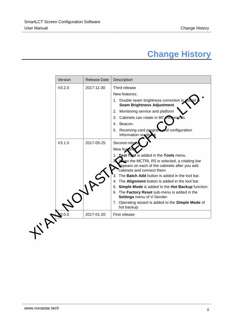
Change History
Version Release Date Description
V3.2.0 2017-11-30 Third release
New features:
1. Double seam brightness correction is added in
Seam Brightness Adjustment.
2. Monitoring service and platform
3. Cabinets can rotate in 90° increments.
4. Beacon.
5. Receiving card program and configuration
information readback
V3.1.0 2017-05-25 Second release
New features:
1. Test Tool is added in the Tools menu.
2. When the MCTRL R5 is selected, a rotating bar
appears on each of the cabinets after you add
cabinets and connect them.
3. The Batch Add button is added in the tool bar.
4. The Alignment button is added in the tool bar.
5. Simple Mode is added to the Hot Backup function.
6. The Factory Reset sub-menu is added in the
Settings menu of V-Sender.
7. Operating wizard is added to the Simple Mode of
hot backup.
V3.0.0 2017-01-20 First release
XI'AN N
OVASTAR TE
CH CO.,LTD.

SmartLCT Screen Configuration Software
User Manual Contents
www.novastar.tech iii
Contents
Change History .................................................................................................................. ii
Contents ............................................................................................................................ iii
1 Introduction ..................................................................................................................... 1
1.1 System Architecture ..................................................................................................................................... 2
1.2 Configuration List ......................................................................................................................................... 2
1.3 Software Installation .................................................................................................................................... 2
2 User Interface .................................................................................................................. 3
3 Language ......................................................................................................................... 6
4 Offline Operation............................................................................................................. 7
4.1 New Projects ................................................................................................................................................ 7
4.2 Screen Configuration ................................................................................................................................... 8
4.2.1 Adding Cabinets ........................................................................................................................................ 8
4.2.2 Cabinet Connection .................................................................................................................................. 9
4.3 Sending Configuration Information ............................................................................................................ 12
4.4 Other Operations ....................................................................................................................................... 13
4.4.1 Adding Devices ....................................................................................................................................... 13
4.4.2 Hot Backup ............................................................................................................................................. 13
5 Online Operation ........................................................................................................... 16
5.1 New Projects .............................................................................................................................................. 16
5.2 Screen Configuration ................................................................................................................................. 17
5.2.1 Adding Cabinets ...................................................................................................................................... 17
5.2.2 Cabinet Connection ................................................................................................................................ 17
5.3 Seam Brightness Adjustment .................................................................................................................... 17
5.3.1 Module Mode .......................................................................................................................................... 18
5.3.2 Cabinet Mode ......................................................................................................................................... 18
5.3.3 Border Selection ..................................................................................................................................... 18
5.3.4 Seam Brightness Parameter Adjustment ............................................................................................... 19
5.3.5 Display Window Modes .......................................................................................................................... 19
5.3.6 Deleting Inforamtion................................................................................................................................ 20
5.4 Seam Brightness Restoration .................................................................................................................... 20
5.5 Monitoring .................................................................................................................................................. 21
5.5.1 Real-Time Monitoring ............................................................................................................................. 22
5.5.2 BER Detection ........................................................................................................................................ 23
XI'AN N
OVASTAR TE
CH CO.,LTD.
SmartLCT Screen Configuration Software
User Manual Contents
www.novastar.tech iv
5.5.3 Version Information ................................................................................................................................. 23
5.5.4 Monitoring Configuration ........................................................................................................................ 23
5.6 Sending Configuration Information ............................................................................................................ 24
5.7 V-Sender .................................................................................................................................................... 24
5.7.1 Accessing V-Sender................................................................................................................................ 24
5.7.2 Adding Devices ....................................................................................................................................... 25
5.7.3 Screen Control ........................................................................................................................................ 26
5.7.4 Template Settings ................................................................................................................................... 27
5.7.5 Device Properties ................................................................................................................................... 27
5.7.6 Picture in Picture (PIP) ........................................................................................................................... 28
5.7.7 Mosaic .................................................................................................................................................... 31
5.8 Other Operations ....................................................................................................................................... 31
5.8.1 Hot Backup ............................................................................................................................................. 31
5.8.2 Beacon .................................................................................................................................................... 31
5.8.3 Mapping .................................................................................................................................................. 31
6 Features ......................................................................................................................... 32
6.1 Building Screens like Building Blocks ........................................................................................................ 32
6.2 Rotating in 90° Increments ........................................................................................................................ 32
6.3 360° Free Rotation..................................................................................................................................... 32
6.4 LED Display Test ....................................................................................................................................... 34
6.5 Receiving Card Program and Configuration Parameter Readback .......................................................... 35
6.6 Exporting Screen Configuration Information as Image .............................................................................. 36
XI'AN N
OVASTAR TE
CH CO.,LTD.

SmartLCT Screen Configuration Software
User Manual 1 Introduction
www.novastar.tech 1
1 Introduction
Overview
SmartLCT is the new generation of screen configuration software from NovaStar. Working with LED display controllers, it allows smart configuration of various complex LED displays, including building-block screen configuration, offline (online) design, seam brightness adjustment, cabinet rotation, etc. SmartLCT makes screen configuration much easier and further enhances user experience.
Key features:
Angles of rotation supports the multiples of 90° (working with the Armor series receiving cards).
Supports 360° free rotation (working with the MCTRL R5).
Supports 18bit+.
Supports ClearView.
Supports receiving card program and configuration information readback.
Supports the monitoring service and platform.
Screen configuration like building blocks.
Supports seam brightness adjustment.
The functions of video controllers can be set on V-Sender.
Supports hot backup.
The canvas can be exported as an image.
Operating environment: OS X, Windows 7 or later. XI'AN N
OVASTAR TE
CH CO.,LTD.
SmartLCT Screen Configuration Software
User Manual 1 Introduction
www.novastar.tech 2
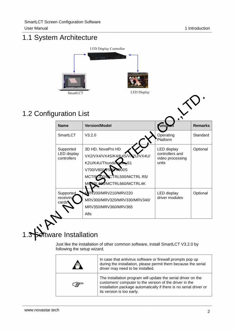
1.1 System Architecture
1.2 Configuration List
Name Version/Model Function Remarks
SmartLCT V3.2.0 Operating Platform
Standard
Supported LED display controllers
3D HD, NovaPro HD
VX2/VX4/VX4S/K4/K4S/VX2U/VX4U/
K2U/K4U/Thunderview_S1
V700/V800/V900/V900S
MCTRL300/MCTRL500/MCTRL R5/
MCTRL600/MCTRL660/MCTRL4K
LED display controllers and video processing units
Optional
Supported receiving cards
MRV200/MRV210/MRV220
MRV300/MRV320/MRV330/MRV340/
MRV350/MRV360/MRV365
A8s
LED display driver modules
Optional
1.3 Software Installation
Just like the installation of other common software, install SmartLCT V3.2.0 by following the setup wizard.
In case that antivirus software or firewall prompts pop up during the installation, please permit them because the serial driver may need to be installed.
The installation program will update the serial driver on the customers' computer to the version of the driver in the installation package automatically if there is no serial driver or its version is too early.
XI'AN N
OVASTAR TE
CH CO.,LTD.
SmartLCT Screen Configuration Software
User Manual 2 User Interface
www.novastar.tech 3
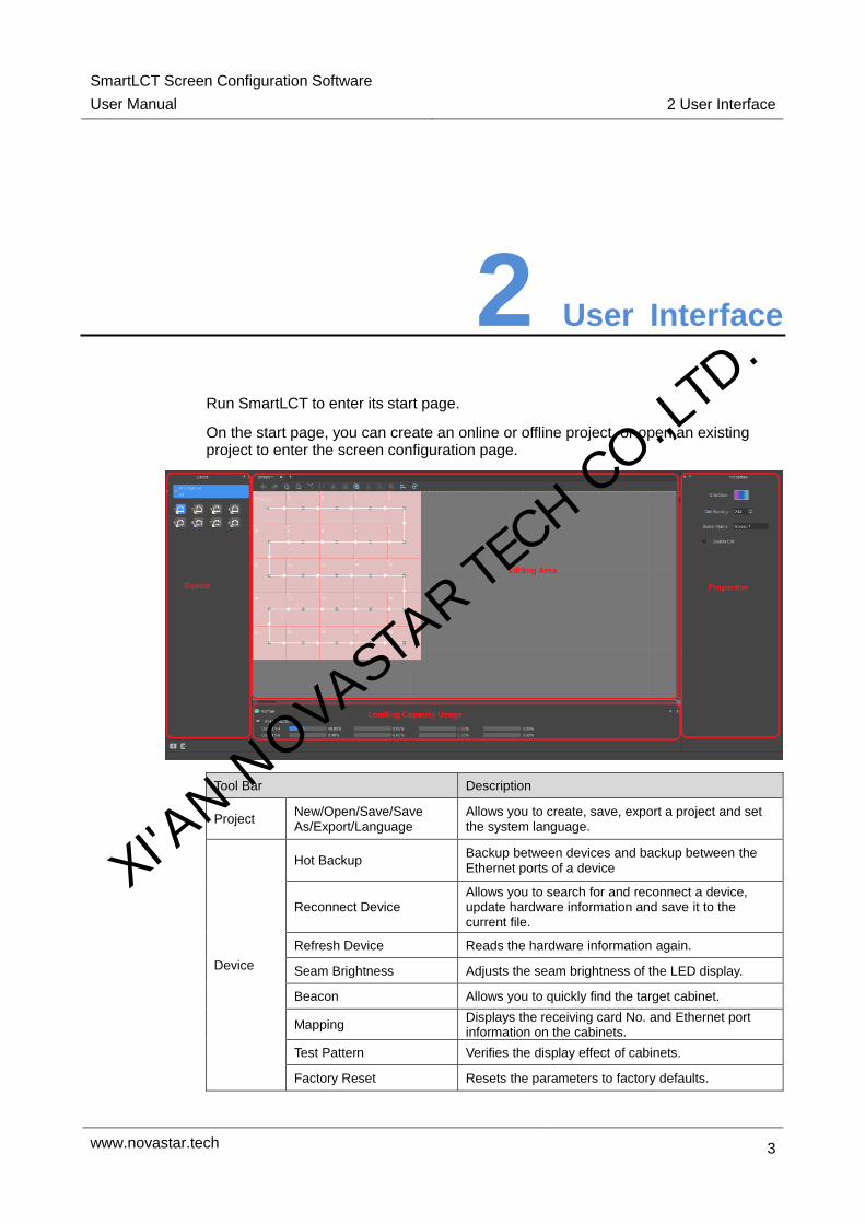
2 User Interface
Run SmartLCT to enter its start page.
On the start page, you can create an online or offline project, or open an existing project to enter the screen configuration page.
Tool Bar Description
Project New/Open/Save/Save As/Export/Language
Allows you to create, save, export a project and set the system language.
Device
Hot Backup Backup between devices and backup between the Ethernet ports of a device
Reconnect Device Allows you to search for and reconnect a device, update hardware information and save it to the current file.
Refresh Device Reads the hardware information again.
Seam Brightness Adjusts the seam brightness of the LED display.
Beacon Allows you to quickly find the target cabinet.
Mapping Displays the receiving card No. and Ethernet port information on the cabinets.
Test Pattern Verifies the display effect of cabinets.
Factory Reset Resets the parameters to factory defaults.
XI'AN N
OVASTAR TE
CH CO.,LTD.
SmartLCT Screen Configuration Software
User Manual 2 User Interface
www.novastar.tech 4
Edit
Cabinet Management Allows you to add cabinets and set cabinet size.
Cabinet Connection Allows you to choose the cabinet connection type.
Advanced Allows you to set cabinet display status in the editing area and the snapping mode.
View Includes front view and rear view.
Delete Connection Removes the lines between cabinets.
Send Sends the display configuration file to hardware devices.
Save to Hardware(online operation)
Sends and saves the screen configuration file to hardware devices.
Monitor
Real-Time Monitoring Monitors cabinet status in real time.
BER Detection Detects data packet loss during the communication between receiving cards.
Version Information Displays the Ethernet port information and program version information of the controllers and receiving cards.
Monitoring Configuration Allows you to configure the parameters to be monitored.
Tools
Calculator Launches the Windows calculator.
Test Tool
A LED display test tool developed by NovaStar can be used for editing and testing the display window. It allows you to open the preview window on the desktop and view the result of the test.
Help User Manual User manual of SmartLCT
About Software information
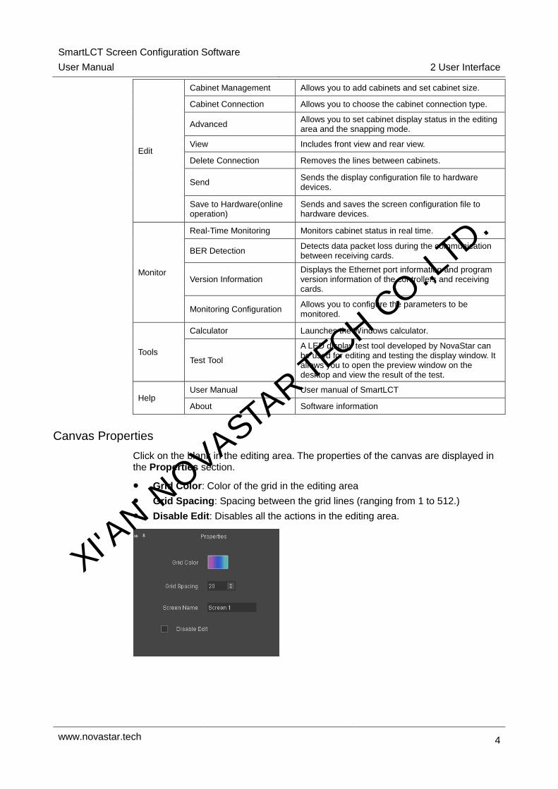
Canvas Properties
Click on the blank in the editing area. The properties of the canvas are displayed in the Properties section.
Grid Color: Color of the grid in the editing area
Grid Spacing: Spacing between the grid lines (ranging from 1 to 512.)
Disable Edit: Disables all the actions in the editing area.
XI'AN N
OVASTAR TE
CH CO.,LTD.

SmartLCT Screen Configuration Software
User Manual 2 User Interface
www.novastar.tech 5
Device Properties
Click to select a cabinet. The properties of the device is displayed in the Properties section. In the following description, the MCTRL 4K is taken as an example.
Connection 1-2-3: Denotes that the sending card No. is 1, Ethernet port No. is 2, and the receiving card No. is 3.
Mapping Position: Position of the cabinet on the LED display
Position: Position of the cabinet on the canvas
Test Pattern: Test patterns are used for verifying the display effect of the screen.
When the connected device supports rotation function (Currently, only the MCTRL R5 supports rotation function), the center and angle of rotation can be set in the properties of the device to achieve free rotation of the LED display.
Loading Capacity Usage
The Loading Capacity Usage section displays the usage of the loading capacity of Ethernet ports.
Blue: Denotes the loading capacity is normal. The length of the blue bar indicates the used capacity of the Ethernet port.
Red: Beyond the loading capacity.
XI'AN N
OVASTAR TE
CH CO.,LTD.
SmartLCT Screen Configuration Software
User Manual 3 Language
www.novastar.tech 6
3 Language
SmartLCT is available in German, French, Russian, Spanish, Chinese and English.
You can change the language through any of the following methods.
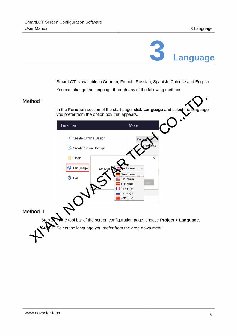
Method I
In the Function section of the start page, click Language and select the language you prefer from the option box that appears.
Method II
Step 1 In the tool bar of the screen configuration page, choose Project > Language.
Step 2 Select the language you prefer from the drop-down menu.
XI'AN N
OVASTAR TE
CH CO.,LTD.

SmartLCT Screen Configuration Software
User Manual 4 Offline Operation
www.novastar.tech 7
4 Offline Operation
4.1 New Projects
Run SmartLCT. In the Function section of the start page, click Create Offline Design to enter the Create a new project page.
Project Name: Name the project and choose a save path for the project.
Device Selection: Select a video controller. Here the VX4S is taken as an example.
Cabinet Selection: Select the manufacturer and type of the cabinets.
Screen Size: Set the columns and rows of the cabinets.
Max. Load: The maximum screen width and height that can be loaded by the device.
Connection Type: Select the connection type of the cabinets. You can select Auto Connect.
Cabinet Management
① Export the selected cabinets: Export the cabinet file.
XI'AN N
OVASTAR TE
CH CO.,LTD.

SmartLCT Screen Configuration Software
User Manual 4 Offline Operation
www.novastar.tech 8
② Export all: Export all the cabinet files.
③ Delete: Delete cabinet files.
④ Add: Add and import cabinet files.
⑤ Edit: Edit cabinet files.
Creating Modes
You can choose Normal Mode or Smart Mode when creating a new project.
Normal Mode: You only need to edit the project name, choose the save path, and select the cabinet.
Smart Mode: For details, see 4.1 New Project.
4.2 Screen Configuration
After an offline project is created, you will enter the screen configuration page.
4.2.1 Adding Cabinets
Step 1 Select device type and Ethernet port type.
Step 2 Choose Edit > Cabinet Management. Click the following icons to select the cabinet type.
: Clicking this icon allows you to add cabinets in batches.
: Clicking this icon allows you to add a single cabinet.
Step 3 Move the mouse to the editing area and click to add cabinets.
XI'AN N
OVASTAR TE
CH CO.,LTD.

SmartLCT Screen Configuration Software
User Manual 4 Offline Operation
www.novastar.tech 9
4.2.2 Cabinet Connection
Connecting Cabinets
After cabinets are added, you need to connect the cabinets with lines. SmartLCT offers two methods for you to connect the cabinets.
Method I: Auto connect
Step 1 When you create a new project, select Auto Connect in smart mode.
Step 2 Click OK to enter the screen configuration page. The cabinets are added in the editing area and connected with lines automatically.
Note: When you add new cabinets to the editing area, lines between cabinets appear automatically. You can stop adding cabinets with a right click or by pressing Esc on the keyboard.
II: Manually connect
Step 1 On the screen configuration page, add cabinets and select any of the following methods to connect the cabinets manually.
Select the target cabinets. In the Cabinet Connection section of the tool bar, select a connection type.
Click to select the center of the first target cabinet and then point to the center of the second cabinet. A line appears between these two centers. You can now move on to the third cabinet and so forth.
Note: Choose Edit > Advanced to select the method to connect cabinets.
Grouping Cabinets
Step 1 Select the target cabinets and click (or right click to choose Group).
Step 2 In the Properties section, set the name and color of the group of cabinets.
The grouped cabinets will be edited as a whole.
XI'AN N
OVASTAR TE
CH CO.,LTD.

SmartLCT Screen Configuration Software
User Manual 4 Offline Operation
www.novastar.tech 10
Deleting Cabinet Connection
Select the target cabinets and click in the tool bar (or right click to choose Delete Connection) to remove the connection between the cabinets.
Setting Cabinet Offset
After cabinets are added, a fixed coordinate system will be generated in the editing area.
Step 1 Click , and you can drag a cabinet to change its position relative to the dashed box.
Step 2 Click to quit the edit.
XI'AN N
OVASTAR TE
CH CO.,LTD.

SmartLCT Screen Configuration Software
User Manual 4 Offline Operation
www.novastar.tech 11
Rotating Cabinets
When the added device supports rotation function, rotate the cabinets according to the following steps.
Step 1 Click . Click and rotate the rotation bar (or set the angle of rotation) to rotate the cabinets to the target position.
Step 2 Click to quit the edit.
XI'AN N
OVASTAR TE
CH CO.,LTD.

SmartLCT Screen Configuration Software
User Manual 4 Offline Operation
www.novastar.tech 12
4.3 Sending Configuration Information
Step 1 In the tool bar, click .
Step 2 Click Yes in the prompt box that appears.
Step 3 In the Match Device dialog box that appears, select the matched online device.
Step 4 Click OK.
XI'AN N
OVASTAR TE
CH CO.,LTD.

SmartLCT Screen Configuration Software
User Manual 4 Offline Operation
www.novastar.tech 13
4.4 Other Operations
4.4.1 Adding Devices
Step 1 At the bottom left of the Device section, click . The Add Devices dialog box appears.
Step 2 Select device type, enter the number of the devices to be cascaded, and then click Add.
Step 3 Click OK.
Note: Multiple devices can be added for a screen and multiple Ethernet ports can be added for a device.
4.4.2 Hot Backup
Choose Device > Hot Backup. The Hot Backup page appears. For detailed operation, see the page navigation.
The hot backup includes Ethernet port backup and device backup.
Hot backup is only available for the devices with the same communication ports.
After device backup is set, the Ethernet ports of the backup device will be the backup of the corresponding ports of the master device. The backup relations cannot be crossed and removed.
Advanced Mode
Step 1 The Add page appears.
XI'AN N
OVASTAR TE
CH CO.,LTD.

SmartLCT Screen Configuration Software
User Manual 4 Offline Operation
www.novastar.tech 14
Step 2 Set the serial numbers of the device and Ethernet port to be backed up.
Step 3 Click Add.
Step 4 Click Save.
Simple Mode
In simple mode, users are not allowed to self-define the corresponding backup Ethernet ports during Ethernet port backup and device backup.
Ethernet port backup
Step 1 Add a device to the editing area.
Step 2 Click , as shown in the figure below.
Note:
When the Ethernet ports are backed up, click at the top right of the device to remove the backup.
Click between two Ethernet ports to delete the line.
Click at the top right of the device to delete the device.
Device backup
Step 1 Add devices that requires backup to the editing area.
Step 2 Drag a device onto another device, and the backup can be done automatically. Or click the small triangle in the right side of the device, drag to the small triangle of the other device and click to complete the backup.
Note:
When the backup is done, the icon appears on the line between the two devices. Click this icon to switch between master and backup.
XI'AN N
OVASTAR TE
CH CO.,LTD.

SmartLCT Screen Configuration Software
User Manual 4 Offline Operation
www.novastar.tech 15
Click at the top right of a device to delete the device.
Click at the top right of the dashed box to remove the backup.
Master/Backup device switching
Before backup, click the toggle button on the right of a device to set it as the master device or backup device.
Table 4-1 Ethernet port description
Icon Description Icon Description
Connection of the primary port is not available.
Connection of the primary port is available.
The backup port is enabled.
The port is not backed up.
The backup port is not enabled.
The port is backed up.
Backup device Master device
Note: Devices that can be set as the maser device or backup device independently include VX2, VX2U, VX4, VX4S, VX4U, V700, V800, V900, NovaPro HD, MCTRL R5, MCTRL4K, K4U, K4S, K4, K2U, 3D HD.
XI'AN N
OVASTAR TE
CH CO.,LTD.

SmartLCT Screen Configuration Software
User Manual 5 Online Operation
www.novastar.tech 16
5 Online Operation
5.1 New Projects
Step 1 Run SmartLCT. On the start page, click next to Device List to refresh the device list and screen list.
Step 2 In the Function section, click Create Online Design to enter the Create a new project page.
Project Name: Name the project and choose a save path for the project.
Cabinet Selection: Select the manufacturer and type of the cabinets.
Screen Size: Set the columns and rows of the cabinets.
Max. Load: The maximum screen width and height that can be loaded by the device.
Connection Type: Select the connection type of the cabinets.
XI'AN N
OVASTAR TE
CH CO.,LTD.

SmartLCT Screen Configuration Software
User Manual 5 Online Operation
www.novastar.tech 17
5.2 Screen Configuration
After an online design is created, the screen configuration page will be displayed.
5.2.1 Adding Cabinets
Step 1 Select an Ethernet port type.
Step 2 Choose Edit > Cabinet Management and click the following icons to select the cabinet type.
: Clicking this icon allows you to add cabinets in batches.
: Clicking this icon allows you to add a single cabinet.
Step 3 Move the mouse to the editing area and click to add cabinets.
5.2.2 Cabinet Connection
For detailed operation of cabinet configuration, see 4.2.2 Cabinet Connection.
5.3 Seam Brightness Adjustment
Before you begin: Configure the LED display (that is, add cabinets and connect them).
Step 1 Choose Device > Seam Brightness > Seam Brightness Adjustment to enter the seam brightness adjustment page.
Step 2 Select the border of the target cabinet.
Step 3 Adjust the seam brightness parameters.
XI'AN N
OVASTAR TE
CH CO.,LTD.

SmartLCT Screen Configuration Software
User Manual 5 Online Operation
www.novastar.tech 18
Send: Clicking this button will send the seam brightness adjustment information to the sending card.
Save to HW: Clicking this button will save the seam brightness adjustment parameters to hardware.
Save: Clicking this button will save the current seam brightness adjustment information.
5.3.1 Module Mode
Step 1 In the tool bar, click . The Area Splitting page appears.
Step 2 Set the number of rows and columns (as shown in the figure below, a cabinet is split into 2 rows and 2 columns). Click OK.
5.3.2 Cabinet Mode
In the tool bar, click to recover the split cabinet.
5.3.3 Border Selection
Selection methods include Select row and column, Column selection and Row selection.
In the tool bar, clicking allows you to select all the borders of the cabinets, as shown in the first figure below.
In the tool bar, clicking allows you to select the horizontal borders of the cabinets, as shown in the second figure below.
In the tool bar, clicking allows you to select the vertical borders of the cabinets, as shown in the third figure below.
XI'AN N
OVASTAR TE
CH CO.,LTD.

SmartLCT Screen Configuration Software
User Manual 5 Online Operation
www.novastar.tech 19
5.3.4 Seam Brightness Parameter Adjustment
After the borders of cabinets are selected, details of the LEDs in the selected cabinet borders will be displayed on the right of the editing area. LED details of the right border of the cabinet 4 are shown in the figure below.
Select some of the LEDs, drag the slider next to Selected Area Parameter Adjustment to adjust the parameter (which defaults to 1.000). The adjustment result is displayed on the border of the cabinet.
Table 5-1 Meanings of the colors of the LEDs
Gray Indicates the LED is not
selected and the
parameter is not
adjusted.
Blue Indicates the LED is
selected and the
parameter is not
adjusted.
Light green Indicates the LED is not
selected and the
parameter is already
adjusted.
Dark green Indicates the LED is
selected and the
parameter is already
adjusted.
5.3.5 Display Window Modes
In the tool bar, click to switch the display window mode (between main display and extended display).
In the tool bar, click to show the dashed box of the LEDs on the border of the selected cabinet on the display window.
XI'AN N
OVASTAR TE
CH CO.,LTD.

SmartLCT Screen Configuration Software
User Manual 5 Online Operation
www.novastar.tech 20
In the tool bar, click to show or hide the display window.
In the tool bar, click to show or hide the selection area (which is the editing area of the seam brightness adjustment page).
Showing/Hiding Cabinet Numbers
In the tool bar, click to show or hide cabinet numbers on the display window.
The keyboard shortcuts for operation is displayed at the top left of the display window. See the following description for details.
SHIFT+F1: Show/Hide prompts.
SHIFT+E: Main/Extended display
SHIFT+H: Show/Hide the display window.
Display Window Background
In the tool bar, clicking allows you to select the background color of the display window.
5.3.6 Deleting Inforamtion
In the tool bar, clicking will deselect the borders of the cabinets.
In the tool bar, clicking will clear the settings and restore the cabinets to the original state.
5.4 Seam Brightness Restoration
Step 1 Choose Device > Seam Brightness > Restore Seam Brightness. The Restore Seam Brightness window appears.
Step 2 Click on the right of Seam Brightness Adjustment File to select a save path for the file.
Step 3 Select the screen to be restored.
Step 4 Click Restore. XI'AN N
OVASTAR TE
CH CO.,LTD.

SmartLCT Screen Configuration Software
User Manual 5 Online Operation
www.novastar.tech 21
Double Seam Brightness Correction
Before you begin: Connect the device to receiving cards.
Type "admin" with your keyboard. The page below appears.
Save to Factory Area: Saves seam brightness adjustment parameters to the factory area of the receiving card. These parameters will be used for maintenance after the cabinet is returned to factory.
Restore to Factory Area: Restores seam brightness adjustment parameters to the parameters last saved in the factory area.
Restore to User Area: Restores seam brightness adjustment parameters to the parameters last saved in the user area.
Save to User Area: Saves seam brightness adjustment parameters to the user area of the receiving cards. These parameters will be used for on-site screen adjustment.
5.5 Monitoring
Real-Time
Monitoring
Monitors the real-time status of the hardware devices such as
receiving cards, multifunction cards.
XI'AN N
OVASTAR TE
CH CO.,LTD.

SmartLCT Screen Configuration Software
User Manual 5 Online Operation
www.novastar.tech 22
BER Detection Detects data packet loss during the communication between receiving
cards.
Version
Information
Displays the device type, communication port status major version and
other versions of the controllers and receiving cards.
Monitoring
Configuration
Allows you to configure the information to be monitored.
5.5.1 Real-Time Monitoring
A: Editing area, where the real-time statuses of cabinets are displayed.
In the editing area, move the mouse and point to a cabinet. The current status of the cabinet will be displayed. Double clicking the target cabinet allows you to view the real-time status of the device and parameters, as shown in the figure below.
B: Monitoring area, where the status statistics of the parameters are displayed.
XI'AN N
OVASTAR TE
CH CO.,LTD.

SmartLCT Screen Configuration Software
User Manual 5 Online Operation
www.novastar.tech 23
C: Device area, where the real-time connection status of the device being monitored is displayed.
In the device area, move the mouse and point to the device icon. The working status of the device is displayed. Clicking the device icon allows you to view the hot backup status of the device and Ethernet ports and the working status of the signal sources.
5.5.2 BER Detection
The statistics of data packet loss during communication between receiving cards is called Bit Error Rate (BER), which is shown by a line chart in the editing area.
Clicking Refresh will refresh the BER of current period so that users can observe the stability of network communication.
5.5.3 Version Information
Clicking on the right of Controller or Receiving Card will refresh the version information.
Clicking will refresh the version information of the Controller and Receiving Card simultaneously.
5.5.4 Monitoring Configuration
Basic Information
You can configure the refresh rules for the real-time monitoring.
Select Auto refresh, and the monitoring information will be automatically refreshed based on the Refresh cycle and the times of Retry you set.
When the Auto refresh is not selected, you need to refresh the monitoring information manually.
Device Configuration
Device configuration allows you to configure the Hot backup status and Signal source status of the device for real-time monitoring.
If Hot backup status is selected, the hot backup status of the device will be monitored in real time.
If Signal source status is selected, clicking Configuration allows you to select the signal source to be monitored.
Screen Configuration
Step 1 Select the target devices (monitoring card, smart module and HUB).
Step 2 Click Configuration to configure the corresponding parameter.
Step 3 Adjust monitoring parameters.
In the Threshold column, drag the slider to adjust the threshold.
XI'AN N
OVASTAR TE
CH CO.,LTD.

SmartLCT Screen Configuration Software
User Manual 5 Online Operation
www.novastar.tech 24
In the Error Detection column, selected parameters are added to Real-Time Monitoring.
Step 4 Click Save.
Threshold description: Green denotes normal, yellow denotes alarm, and red denotes error.
Type Threshold Description
Temperature When the temperature is higher than 66°C, you will see a temperature
alarm in the real-time monitoring.
Humidity When the temperature is higher than 60%, you will see a humidity
alarm in the real-time monitoring.
Voltage When the voltage is lower than 3.40 V, you will see a voltage error in the
real-time monitoring. When the voltage is higher than 3.40 V and lower
than 3.80 V, or higher than 5.50 V, you will see a voltage alarm in the
real-time monitoring.
Fan When the fan speed is lower than 1000 r/m, you will see a fan alarm in
the real-time monitoring.
Note: The figure above only shows some of the monitoring types. The meanings of the thresholds of other types are similar.
5.6 Sending Configuration Information
Step 1 In the tool bar, click .
Step 2 In the prompt box that appears, click OK.
5.7 V-Sender
V-Sender allows you to set the status of the current device and operate the device on PC.
Supported devices include MCTRL300 (MSD300), MCTRL660, VX4S, Pro HD, 3D HD, MCTRL4K.
5.7.1 Accessing V-Sender
Method I
On the start page, click in the Device List section to access V-Sender, as shown in the figure below.
XI'AN N
OVASTAR TE
CH CO.,LTD.

SmartLCT Screen Configuration Software
User Manual 5 Online Operation
www.novastar.tech 25
Method II
In the Device section of the editing page, click to access V-Sender, as shown in the figure below.
5.7.2 Adding Devices
Step 1 At the bottom of the device list, click . The Add Devices page appears.
Step 2 Select the devices you want to add and click OK.
XI'AN N
OVASTAR TE
CH CO.,LTD.
SmartLCT Screen Configuration Software
User Manual 5 Online Operation
www.novastar.tech 26
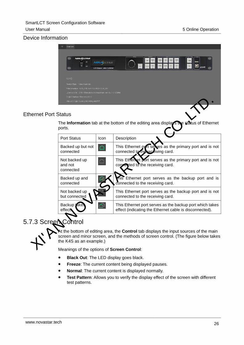
Device Information
Ethernet Port Status
The Information tab at the bottom of the editing area displays the status of Ethernet ports.
Port Status Icon Description
Backed up but not
connected This Ethernet port serves as the primary port and is not
connected to the receiving card.
Not backed up
and not
connected
This Ethernet port serves as the primary port and is not
connected to the receiving card.
Backed up and
connected This Ethernet port serves as the backup port and is
connected to the receiving card.
Not backed up
but connected This Ethernet port serves as the backup port and is not
connected to the receiving card.
Backup takes
effect.
This Ethernet port serves as the backup port which takes
effect (indicating the Ethernet cable is disconnected).
5.7.3 Screen Control
At the bottom of editing area, the Control tab displays the input sources of the main screen and minor screen, and the methods of screen control. (The figure below takes the K4S as an example.)
Meanings of the options of Screen Control:
Black Out: The LED display goes black.
Freeze: The current content being displayed pauses.
Normal: The current content is displayed normally.
Test Pattern: Allows you to verify the display effect of the screen with different test patterns.
XI'AN N
OVASTAR TE
CH CO.,LTD.

SmartLCT Screen Configuration Software
User Manual 5 Online Operation
www.novastar.tech 27
5.7.4 Template Settings
Select a template on the Template tab below the editing area and click to save current configuration parameters as a template. You can save up to 10 templates by default.
Clicking will save current configuration parameters to any of the templates.
Clicking will delete the selected template.
5.7.5 Device Properties
After you set the Input, Color and Output, clicking Apply will complete the settings.
Option Description
Properties Displays the device's type, name, communication port, program version,
etc.
Input Used for switching input source, setting the number of sources, displaying
current resolution, setting the configuration information of the input source
(resolution and refresh rate)
Color Used for adjusting the screen color
Output Mosaic: If the number of the pixels of the LED display exceeds the loading
capacity of the device, the mosaic function is required. For detailed
operation, see 5.7.7 Mosaic.
Note: When Mosaic is selected, the Disable Zoom, Auo Fit, Video
Source Synchronization options under Main Screen are hidden.
Main Screen: Used for setting the parameters of the main screen, such
as capture, output size, output position
Minor Screen: Used for setting the parameters of the minor screen, such
as capture, output size, output position, transparency
Video Source Synchronization: Syncs the parameters of input and
output video sources.
XI'AN N
OVASTAR TE
CH CO.,LTD.
SmartLCT Screen Configuration Software
User Manual 5 Online Operation
www.novastar.tech 28
System Used for system parameter settings
Meanings of the parameters:
LCD Lock: Locks the operation screen of the device. After the operation
screen is locked, buttons on the device are disabled.
Smart Gray Scale: Adjusts the grayscale of the LED display.
Deinterlace: Restores the interlaced video signal to progressive signal.
VGA Auto Adjusting: Adjusts the sampling parameters of VGA input
signal automatically.
ADC Auto Calibration: Adjusts color cast, dimming and other display
problems.
Audio Used for enabling and disabling audio output and adjusting audio output
parameters
Audio types:
Following Mode: Uses the audio source of HDMI.
Constant Mode: Uses the external audio source.
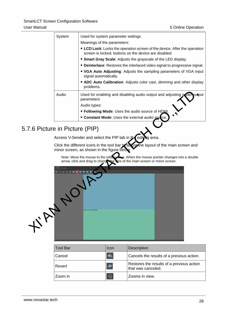
5.7.6 Picture in Picture (PIP)
Access V-Sender and select the PIP tab in the editing area.
Click the different icons in the tool bar to adjust the layout of the main screen and minor screen, as shown in the figure below.
Note: Move the mouse to the editing area. When the mouse pointer changes into a double arrow, click and drag to change the size of the main screen or minor screen.
Tool Bar Icon Description
Cancel Cancels the results of a previous action.
Revert Restores the results of a previous action that was canceled.
Zoom in Zooms in view.
XI'AN N
OVASTAR TE
CH CO.,LTD.

SmartLCT Screen Configuration Software
User Manual 5 Online Operation
www.novastar.tech 29
Zoom out Zooms out view.
Main and Minor Screens Switching
Switches between main and minor screens.
Horizontal Layout N/C
Vertical Layout N/C
In the Middle N/C
Upper Left Layout N/C
Lower Left Layout N/C
Upper Right Layout N/C
Lower Right Layout N/C
Main Screen Settings
You can set the zoom status of the main screen. Three options are provided: Disable Zoom, Customize Zoom and Auto Fit.
Disable Zoom: The size of input image is the same as the size of the output image and only the image offset position is settable.
Customize Zoom: Allows you to set the start position and size for Capture. The captured content will be displayed on the LED display. Output Size is the size of the main screen in the editing area. Output Position is the start position of the current main screen in the editing area.
XI'AN N
OVASTAR TE
CH CO.,LTD.

SmartLCT Screen Configuration Software
User Manual 5 Online Operation
www.novastar.tech 30
Auto Fit: The input image is zoomed to fit the main screen automatically. This mode is suitable for full screen display.
Selecting Apply to All will apply the settings to all the input sources.
After the settings are done, clicking Apply will send the current configuration information to the input source.
Minor Screen Settings
The size and position of the minor screen are editable. Selecting Capture allows you to set the size and start position of the content to be captured. The captured content will be displayed on the LED display.
After the settings are done, clicking Apply will send the current configuration information to the signal source.
XI'AN N
OVASTAR TE
CH CO.,LTD.

SmartLCT Screen Configuration Software
User Manual 5 Online Operation
www.novastar.tech 31
Video Source Synchronization
Video source synchronization allows you to sync the input video source with the output video source.
5.7.7 Mosaic
Prerequisites: When the pixels of the output image exceeds the loading capacity of a single device, the mosaic function will be required.
Step 1 Access V-Sender. On the Output tab, select Mosaic.
Step 2 Set parameters through any of the following methods.
Non-Equal Division: When the loading capacities of each of the VX4S units are different, set the total number of pixels of the LED display, the loading area of current device and the start position.
Equal Division: When the loading capacities of each of the VX4S units are the same, set the total number of pixels of the LED display, the number of mosaic rows and columns, and the start position of the loading area of the current device.
Step 3 After the parameter settings are done, click Apply to send the settings to hardware.
5.8 Other Operations
5.8.1 Hot Backup
For the detailed operation of hot backup, see 4.4.2 Hot Backup.
5.8.2 Beacon
In the editing area, select the target cabinet and click . The corresponding cabinet on the LED display flashes. This function allows you to quickly find the target cabinet.
5.8.3 Mapping
SmartLCT supports the Mapping function.
Choose Device > Mapping. The receiving card numbers and Ethernet port information are displayed on the cabinets of the screen.
XI'AN N
OVASTAR TE
CH CO.,LTD.

SmartLCT Screen Configuration Software
User Manual 6 Features
www.novastar.tech 32
6 Features
6.1 Building Screens like Building Blocks
Step 1 In the Device section, select a device and Ethernet port.
Step 2 In the tool bar, choose Edit > Cabinet Management > or .
Step 3 Move the mouse to the editing area and click to add cabinets.
Step 4 Select one or multiple cabinets and move the mouse to change the position of the cabinet(s). Build different shapes of screens as required.
6.2 Rotating in 90° Increments
Before you begin: Connect the receiving cards or controllers that support rotation to SmartLCT, for example, A8s.
Step 1 In the editing area, select the target cabinet.
Step 2 In the property area, click Reorient to select the angle of cabinet rotation (0°, 90°, 180°, 270°).
6.3 360° Free Rotation
Before you begin: Connect the controller MCTRL R5 to SmartLCT, and the rotation function can be enabled.
Rotation of a Single Cabinet
Step 1 Click and select the cabinets. A rotating bar appears on each of the cabinets.
Step 2 Select any of the rotating bars and drag the mouse. The cabinet rotates around its rotation center.
Step 3 (Optional) Set the rotation center and angles of rotation in the property section on the right.
XI'AN N
OVASTAR TE
CH CO.,LTD.

SmartLCT Screen Configuration Software
User Manual 6 Features
www.novastar.tech 33
Rotation of Grouped Cabinets
Step 1 Click and select the target cabinets.
Step 2 Right click the cabinets and choose Group.
Step 3 Click to select the grouped cabinets. A rotation bar appears on the rotation center of the grouped cabinets.
Step 4 Click the rotation bar and drag the cabinets. The group of cabinets rotates around the rotation center.
Step 5 (Optional) Set the rotation center and angles of rotation in the property section on the right.
XI'AN N
OVASTAR TE
CH CO.,LTD.

SmartLCT Screen Configuration Software
User Manual 6 Features
www.novastar.tech 34
6.4 LED Display Test
Choose Tools > Test Tool to enter the display test tool page (that is, receiving card test page).
Note: Display test is only available for Windows.
Window: Allows you to set window position and size, or hide the window.
Pure Color: Allows you to set window color (pure color), grayscale and refresh rate.
Gradient: Allows you to set the gradient color and levels of the window.
Grid: Allows you to set grid and color and other parameters of the window.
XI'AN N
OVASTAR TE
CH CO.,LTD.
SmartLCT Screen Configuration Software
User Manual 6 Features
www.novastar.tech 35
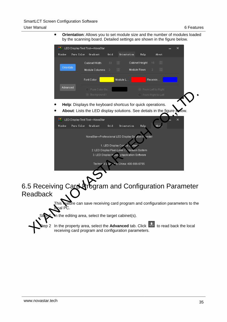
Orientation: Allows you to set module size and the number of modules loaded by the scanning board. Detailed settings are shown in the figure below.
Help: Displays the keyboard shortcus for quick operations.
About: Lists the LED display solutions. See detials in the figure below.
6.5 Receiving Card Program and Configuration Parameter Readback
This feature can save receiving card program and configuration parameters to the local PC.
Step 1 In the editing area, select the target cabinet(s).
Step 2 In the property area, select the Advanced tab. Click to read back the local receiving card program and configuration parameters. XI'AN N
OVASTAR TE
CH CO.,LTD.

SmartLCT Screen Configuration Software
User Manual 6 Features
www.novastar.tech 36
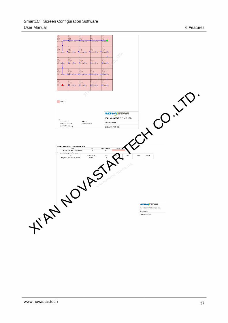
6.6 Exporting Screen Configuration Information as Image
The screen configuration information can be exported as an image,
Step 1 Choose Project > Export. The Export page appears.
Step 2 Set export parameters and information.
Step 3 Click Export to export the image to the local PC.
XI'AN N
OVASTAR TE
CH CO.,LTD.
SmartLCT Screen Configuration Software
User Manual 6 Features
www.novastar.tech 37
XI'AN N
OVASTAR TE
CH CO.,LTD.