smart positioner product manual yt-3700 / 3750 · 2020-04-23 · smart positioner yt-3700 / 3750...
TRANSCRIPT
SMART POSITIONER PRODUCT MANUAL YT-3700 / 3750
YT-3700
YT-3750
Rotork YTC Limited
VERSION 1.10
Smart Positioner YT-3700 / 3750 Product Manual
Ver. 1.10 2
Contents 1 Introduction .................................................................................................................................................5
1.1 General Information for the users .........................................................................................................5
1.2 Manufacturer Warranty .........................................................................................................................5
1.3 Explosion Proof Warning (Only for Intrinsic safety type positioners) ....................................................6
2 Product Description ...................................................................................................................................7
2.1 General .................................................................................................................................................7
2.2 Main Features and Functions ...............................................................................................................7
2.3 Label Description ..................................................................................................................................8
2.4 Product Code ..................................................................................................................................... 13
2.5 Product Specification ......................................................................................................................... 14
2.6 Specification of Digital In, Digital out ................................................................................................. 15
2.7 Certifications ...................................................................................................................................... 16
2.8 Parts and Assembly ........................................................................................................................... 18
2.9 Product Dimension ............................................................................................................................ 20
2.9.1 YT-3700 ......................................................................................................................................... 20
2.9.2 YT-3750 ......................................................................................................................................... 20
3 Installation ................................................................................................................................................ 21
3.1 Safety ................................................................................................................................................. 21
3.2 Tools for installation ........................................................................................................................... 21
3.3 Linear positioner Installation .............................................................................................................. 22
3.3.1 Linear positioner Installation of Standard lever type...................................................................... 22
3.3.2 Safety ............................................................................................................................................. 22
3.3.3 Standard lever type positioner Installation Steps .......................................................................... 23
3.4 Rotary positioner Installation ............................................................................................................. 26
3.4.1 Components................................................................................................................................... 26
3.4.2 Rotary Bracket Information ............................................................................................................ 27
3.4.3 Rotary positioner Installation Steps ............................................................................................... 28
4 Connection - Air ....................................................................................................................................... 29
4.1 Safety ................................................................................................................................................. 29
4.2 Supply Pressure Condition ................................................................................................................ 29
4.3 Piping Condition ................................................................................................................................. 29
4.4 Connection – Piping with actuator ..................................................................................................... 30
4.4.1 Single acting actuator .................................................................................................................... 30
4.4.2 Double acting actuator ................................................................................................................... 30
5 Connection – Power ................................................................................................................................ 31
5.1 Safety ................................................................................................................................................. 31
5.2 Connection ......................................................................................................................................... 32
5.2.1 Standard Terminals ....................................................................................................................... 32
5.2.2 Terminals with micro-limit switch option ........................................................................................ 34
Smart Positioner YT-3700 / 3750 Product Manual
Ver. 1.10 3
5.2.3 Terminals with proximity Limit Switch option ................................................................................. 35
5.3 Ground ............................................................................................................................................... 35
6 Adjustments ............................................................................................................................................. 36
6.1 Limit Switch Adjustment ..................................................................................................................... 36
6.2 A/M switch adjustment ....................................................................................................................... 37
6.3 Orifice Installment .............................................................................................................................. 38
6.3.1 Plate type Orifice Installment ......................................................................................................... 38
7 Optional Sub-PCB Installment ................................................................................................................ 39
7.1 Installation steps ................................................................................................................................ 39
8 Auto Calibration and PCB Operation ..................................................................................................... 41
8.1 Warning .............................................................................................................................................. 41
8.2 LCD display and buttons .................................................................................................................... 41
8.2.1 LCD display and symbols .............................................................................................................. 41
8.2.2 Button and function ........................................................................................................................ 42
8.3 Menu levels ........................................................................................................................................ 43
8.4 RUN Mode Monitor ............................................................................................................................ 44
8.5 Configuration and Operation .............................................................................................................. 45
8.6 Calibration (CALIb) ............................................................................................................................ 49
8.6.1 Acting Type (SINGLE / dOUBLE) .................................................................................................. 49
8.6.2 Auto Calibration 1 (AUTO 1) .......................................................................................................... 50
8.6.3 Auto Calibration 2 (AUTO 2) .......................................................................................................... 50
8.6.4 Travel Zero (TVL ZERO) and Travel end (TVL ENd) .................................................................... 51
8.7 Manual Operation (MAN OPER)........................................................................................................ 52
8.7.1 Manual Operation by Set position (MAN SP) ................................................................................ 52
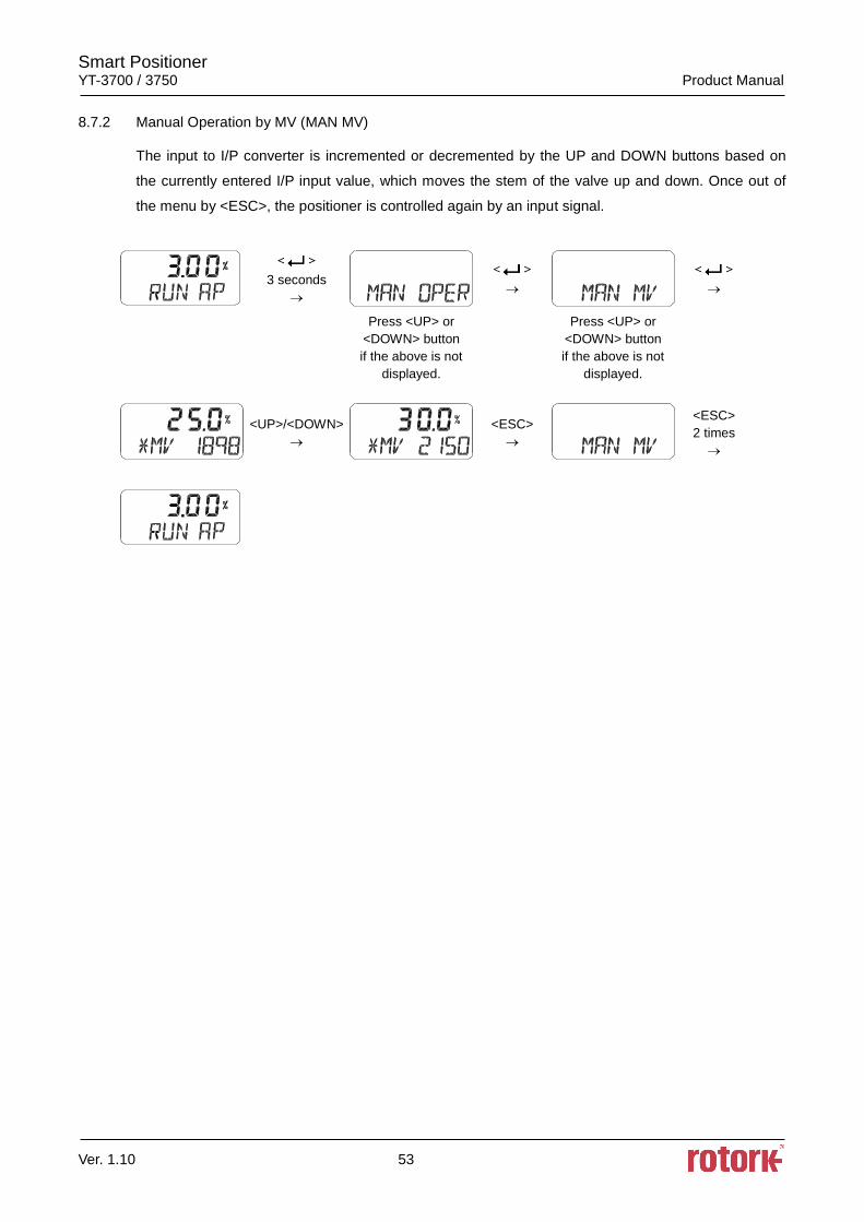
8.7.2 Manual Operation by MV (MAN MV) ............................................................................................. 53
8.8 Control Parameters (CTL PARM) ...................................................................................................... 54
8.8.1 Dead Band (dEAdbANd) ................................................................................................................ 54
8.8.2 Forward P parameter (KP UP) and reverse P parameter (KP dN) ................................................ 55
8.8.3 Forward Integral time parameter (TI UP) and reverse Integral time parameter (TI dN) ................ 55
8.8.4 Forward D parameter (Kd UP) and reverse D parameter (Kd dN) ................................................ 56
8.8.5 Auto Dead band Mode (AUTO db) ................................................................................................ 56
8.8.6 Performance Mode (PER) ............................................................................................................. 57
8.9 Input Configuration (IN CFG) ............................................................................................................. 58
8.9.1 Signal Direction (SIG NORM / REVS) ........................................................................................... 58
8.9.2 Split Range Mode (SPLIT) ............................................................................................................. 59
8.9.3 Custom Split Range Zero (CST ZERO) ......................................................................................... 59
8.9.4 Custom Split Range End (CST ENd) ............................................................................................. 60
8.9.5 Valve Flow Characterization Curves (CHAR) ................................................................................ 60
8.9.6 User Set Characterization 5 Points (U5) ....................................................................................... 61
8.9.7 User Set Characterization 21 Points (U21) ................................................................................... 62
Smart Positioner YT-3700 / 3750 Product Manual
Ver. 1.10 4
8.9.8 Tight Shut Open (TSHUT OP) ....................................................................................................... 63
8.9.9 Tight Shut Close (TSHUT CL) ....................................................................................................... 64
8.9.10 Target Position Ramp Up Rate (RAMP UP) and Target Position Ramp Down Rate (RAMP dN)
65
8.9.11 Digital Input Function (dIF) ........................................................................................................ 67
8.9.12 Digital Input Logic (dI LOGIC) .................................................................................................... 67
8.10 Output Configuration (OUT CFG) ...................................................................................................... 68
8.10.1 Position Transmitter Direction (PTM NORM / REVS) ................................................................ 68
8.10.2 Position Transmitter Zero / End (PTM ZERO / ENd) ................................................................. 69
8.10.3 HART Feedback Direction (HT NORM / REVS) ........................................................................ 70
8.10.4 Back Calculation (bACKCAL oFF / on) ...................................................................................... 71
8.10.5 Digital Output Function (dOF) .................................................................................................... 72
8.10.6 Digital Output Logic (dO LOGIC HI / Lo) ................................................................................... 73
8.10.7 Analog Output Function (AOF) .................................................................................................. 74
8.10.8 Analog Output Logic (AO LOGIC Lo / HI) .................................................................................. 75
8.11 Device Configuration (dEV CFG)....................................................................................................... 76
8.11.1 Action Setting (ACT) .................................................................................................................. 76
8.11.2 Linear Interpolation (ITP oFF / on)............................................................................................. 77
8.11.3 Lock of Parameters (Write Protect, W UNLOCK / LOCK) ......................................................... 77
8.11.4 Actual Position View Mode (View Mode, VI NORM / REVS) .................................................... 78
8.11.5 Polling address setting (POL AddR) .......................................................................................... 78
8.11.6 Factory Reset (dEFAULT oFF / on) ........................................................................................... 79
8.11.7 Positioner Self-Test (SELFTEST) .............................................................................................. 80
8.12 Diagnosis Mode (dIAGNd) ................................................................................................................. 81
8.12.1 Default Alarm Settings ............................................................................................................... 81
8.12.2 Process Status (PS) .................................................................................................................. 83
8.12.3 Device Status (dS) ..................................................................................................................... 84
8.12.4 View Monitoring Counts (VI CNTS) ........................................................................................... 86
8.12.5 Diagnostic Limit Configuration (LIMT CFG) ............................................................................... 87
8.12.6 Reset Alarm Status (RST ALRM oFF / on) ................................................................................ 88
8.12.7 View Event Log (EVT LOG) ....................................................................................................... 89
8.12.8 Partial Stroke Test Record (View PST Result Record, PST RSLT) .......................................... 90
8.12.9 PST Configuration (PST CFG) .................................................................................................. 91
8.12.10 Run PST (PST NOW) ................................................................................................................ 92
8.12.11 Periodic PST Test (PST Schedule, PST SCHd oFF / on) ......................................................... 93
8.13 Position information (INFO) ............................................................................................................... 94
8.14 Status and Alarm Code ...................................................................................................................... 96
9 Main Software Map .................................................................................................................................. 99
Smart Positioner YT-3700 / 3750 Product Manual
Ver. 1.10 5
1 Introduction
1.1 General Information for the users
Thank you for purchasing Rotork YTC Limited products. Each product has been fully inspected after
its production to offer you the highest quality and reliable performance. Please read the product
manual carefully prior to installing and commissioning the product.
Installation, commissioning, and maintenance of the product may only be performed by trained
specialist personnel who have been authorized by the plant operator accordingly.
The manual should be provided to the end-user.
Factory Mutual approved Intrinsically Safe and Non-Incendive units must be Installed Per
drwg SKC_XXXXX_XXXXXX.pdf
CSA approved Intrinsically Safe and Non-Incendive units must be Installed Per drwg SKC-
XXXX.pdf
The manual can be altered or revised without any prior notice. Any changes in product’s
specification, design, and/or any components may not be printed immediately but until the
following revision of the manual.
When the manual refers to “Valve Zero / Zero” means the final valve position upon pneumatic
pressure has been fully exhausted from positioner’s OUT1 port. For example, the valve zero
position may differ between linear direct and reverse actions. (DA/RA)
The manual should not be duplicated or reproduced for any purpose without prior approval from
Rotork YTC Limited, Gimpo-si, South Korea.
In case of any other problems that are not stated in this manual, please make immediate contact
to Rotork YTC Limited.
Positioner is an accessory of the control valve, so please make sure to read the applicable
instruction manual of the control valve prior to installation and operation.
1.2 Manufacturer Warranty
For the safety, it is important to follow the instructions in the manual. Manufacturer will not be
responsible for any damages caused by user’s negligence.
Any modifications or repairs to the product may only be performed if expressed in this manual.
Injuries and physical damages caused by customer’s modifying or repairing the product without
a prior consultation with Rotork YTC Limited will not be compensated. If any alterations or
modifications are necessary, please contact Rotork YTC Limited directly.
The warranty period of the product is (18) months from the date of shipment unless stated
otherwise. Date of shipment can be checked by providing the LOT NO. or SERIAL NO. to us.
Manufacturer warranty will not cover products that have been subjected to abuse, accidents,
alterations, modifications, tampering, negligence, misuse, faulty installation, lack of reasonable
care, repair or service in any way that is not contemplated in the documentation for the product,
or if the model or serial number has been altered, tampered with, defaced or removed; damages
Smart Positioner YT-3700 / 3750 Product Manual
Ver. 1.10 6
that occurs in shipment, due to act of God, failure due to power surge, or cosmetic damage.
Improper or incorrectly performed maintenance will void this limited warranty.
For detailed warranty information, please contact the corresponding local Rotork YTC Limited
office or main office in South Korea.
1.3 Explosion Proof Warning (Only for Intrinsic safety type positioners)
Please ensure the unit is being used and installed in conformity with local, regional, and national
explosion proof within the proper safety barrier environment.
Refer to “2.7 Certifications”
Explosion proof type of cables and gaskets should be used, when explosion gases are present
at the installation site.
Positioner has 2 ports for power connection. Explosion proof type wires and packing should be
used. Blind plug is required when any port is not being used.
Ring terminal with surface area of more than 1.25mm2 with M4 spring washer should be used to
connect the power.
For external ground terminal, ring terminal with surface area of more than 5.5mm2 should be
used.
Wiring in these applications shall utilize appropriate methods for Class I, Division 2 / Zone 2
Substitution of components may impair intrinsic safety.
Substitution of components may impair suitability for Class I, Division 2
(FM/CSA: Class I, Division1, Division 2)
EXPLOSION HAZARD. Do not connect or disconnect wiring unless all sources of power have
been removed or the area is known to be non-hazardous.
(French) RISQUE D'EXPLOSION. Ne pas raccorder ou débrancher le câblage à moins Toutes
les sources d'énergie ont été enlevées ou la zone est connue pour être non dangereux.
The enclosure of model YT-3700 contains aluminum, which is considered to constitute a
potential risk of ignition when subjected to impact or friction. Care must be used during
installation in locating this equipment to prevent impact or friction
Some of the enclosure parts are made of non-metallic materials. To prevent the risk of
Electrostatic sparking, clean the enclosure only with a damp cloth.
The product must be installed in such a manner as to minimize the risk of impact or friction with
other metal surfaces.
For Intrinsically Safe installations, the product must be connected to suitably rated intrinsically
safe equipment, and must be installed in accordance with applicable intrinsically safe installation
standards.
Smart Positioner YT-3700 / 3750 Product Manual
Ver. 1.10 7
2 Product Description
2.1 General
YT-3700 / 3750 series Smart Valve Positioner accurately controls valve stroke in response to an input
signal of 4~20mA from the controller. Built-in micro-processor optimizes the positioner ’s performance
and provides unique functions such as Auto-Calibration, PID Control, and HART Protocol
Communications.
2.2 Main Features and Functions
LCD display enables users to monitor the positioner status.
User will easily understand the method of using 4 buttons because it work same in all versions of
firmware interfaces.
When unexpected situation like momentary blackout happens, our positioner boot-time only take
0.5 second and this can minimize the travel of valve which consequentially increase the safety of
system.
Positioner operates normally even there are sudden changes in supply pressure and / or high
vibration environment.
The method of Auto Calibration is very simple.
As an advantage of having very low air consumption, It could greatly reduce operating costs in
large-scale plants.
It is compatible with most of controllers.
Orifices can be installed even in the field to minimize the hunting occurrence and optimize
operating conditions.
Various information about positioner can be processed by HART communication.
Valve system becomes more stable by outputting analog feedback signal.
Different valve characteristics can be adjusted – Linear, Quick Open, Equal Percentage, and
User Set which user can make 5 or 21 points characterizations.
Tight Shut – Close and Shut - Open can be set.
PID parameters can be adjusted in the field without any additional communicator.
A/M switch can be used to direct supply air to the actuator or to manually operate the positioner
or valve without any signal.
Split range 4~12mA or 12~20mA can be set.
Operating temperature for positioners is -30 ~ 85 or -40 ~ 85 (Please check certified
explosion proof temperature)
Hand calibration function can set Zero point or End point manually.
It has IP66 protection grade.
Polyester powder coating resists the corrosion process. (except YT-3750).
Maintenance of the positioner is easy because of modularized inner structure.
Smart Positioner YT-3700 / 3750 Product Manual
Ver. 1.10 8
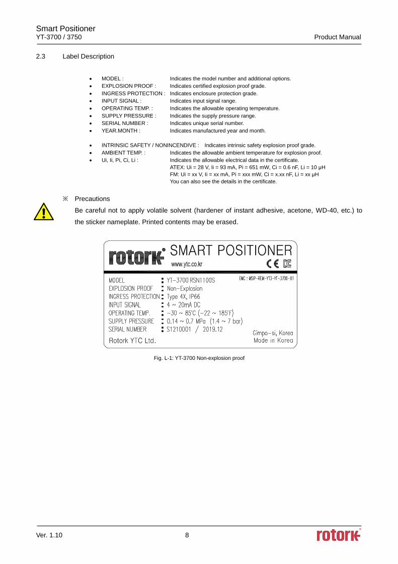
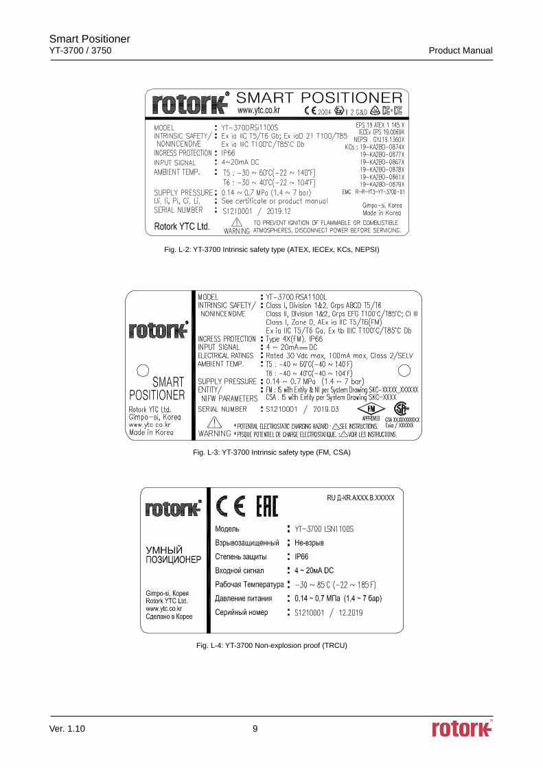
2.3 Label Description
• MODEL : Indicates the model number and additional options.
• EXPLOSION PROOF : Indicates certified explosion proof grade.
• INGRESS PROTECTION : Indicates enclosure protection grade.
• INPUT SIGNAL : Indicates input signal range.
• OPERATING TEMP. : Indicates the allowable operating temperature.
• SUPPLY PRESSURE : Indicates the supply pressure range.
• SERIAL NUMBER : Indicates unique serial number.
• YEAR.MONTH : Indicates manufactured year and month.
• INTRINSIC SAFETY / NONINCENDIVE : Indicates intrinsic safety explosion proof grade.
• AMBIENT TEMP. : Indicates the allowable ambient temperature for explosion proof.
• Ui, Ii, Pi, Ci, Li : Indicates the allowable electrical data in the certificate.
ATEX: Ui = 28 V, Ii = 93 mA, Pi = 651 mW, Ci = 0.6 nF, Li = 10 μH
FM: Ui = xx V, Ii = xx mA, Pi = xxx mW, Ci = x.xx nF, Li = xx μH
You can also see the details in the certificate.
※ Precautions
Be careful not to apply volatile solvent (hardener of instant adhesive, acetone, WD-40, etc.) to
the sticker nameplate. Printed contents may be erased.
Fig. L-1: YT-3700 Non-explosion proof
Smart Positioner YT-3700 / 3750 Product Manual
Ver. 1.10 9
Fig. L-2: YT-3700 Intrinsic safety type (ATEX, IECEx, KCs, NEPSI)
Fig. L-3: YT-3700 Intrinsic safety type (FM, CSA)
Fig. L-4: YT-3700 Non-explosion proof (TRCU)
Smart Positioner YT-3700 / 3750 Product Manual
Ver. 1.10 10
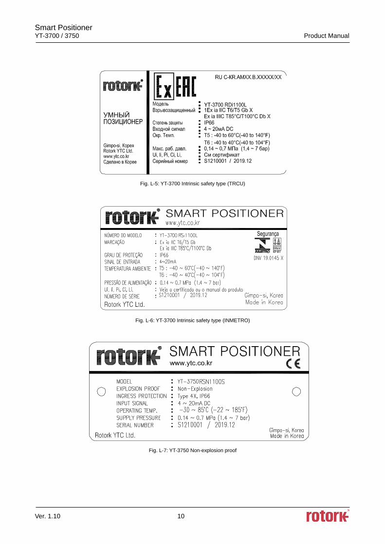
Fig. L-5: YT-3700 Intrinsic safety type (TRCU)
Fig. L-6: YT-3700 Intrinsic safety type (INMETRO)
Fig. L-7: YT-3750 Non-explosion proof
Smart Positioner YT-3700 / 3750 Product Manual
Ver. 1.10 11
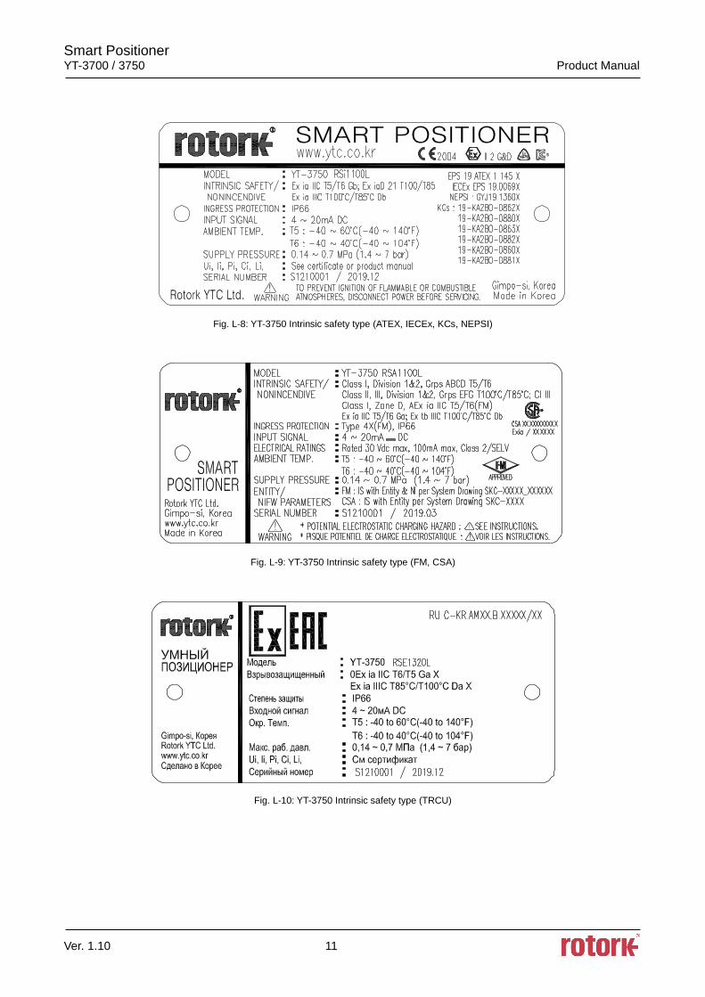
Fig. L-8: YT-3750 Intrinsic safety type (ATEX, IECEx, KCs, NEPSI)
Fig. L-9: YT-3750 Intrinsic safety type (FM, CSA)
Fig. L-10: YT-3750 Intrinsic safety type (TRCU)
Smart Positioner YT-3700 / 3750 Product Manual
Ver. 1.10 12
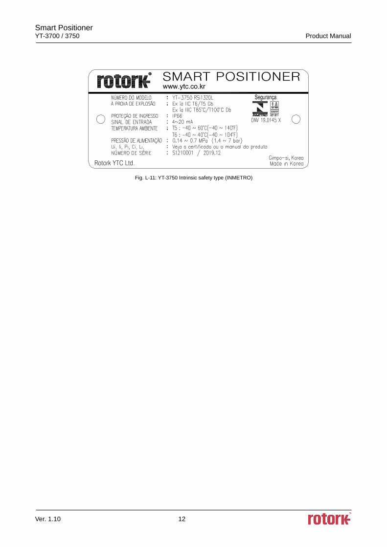
Fig. L-11: YT-3750 Intrinsic safety type (INMETRO)
Smart Positioner YT-3700 / 3750 Product Manual
Ver. 1.10 13
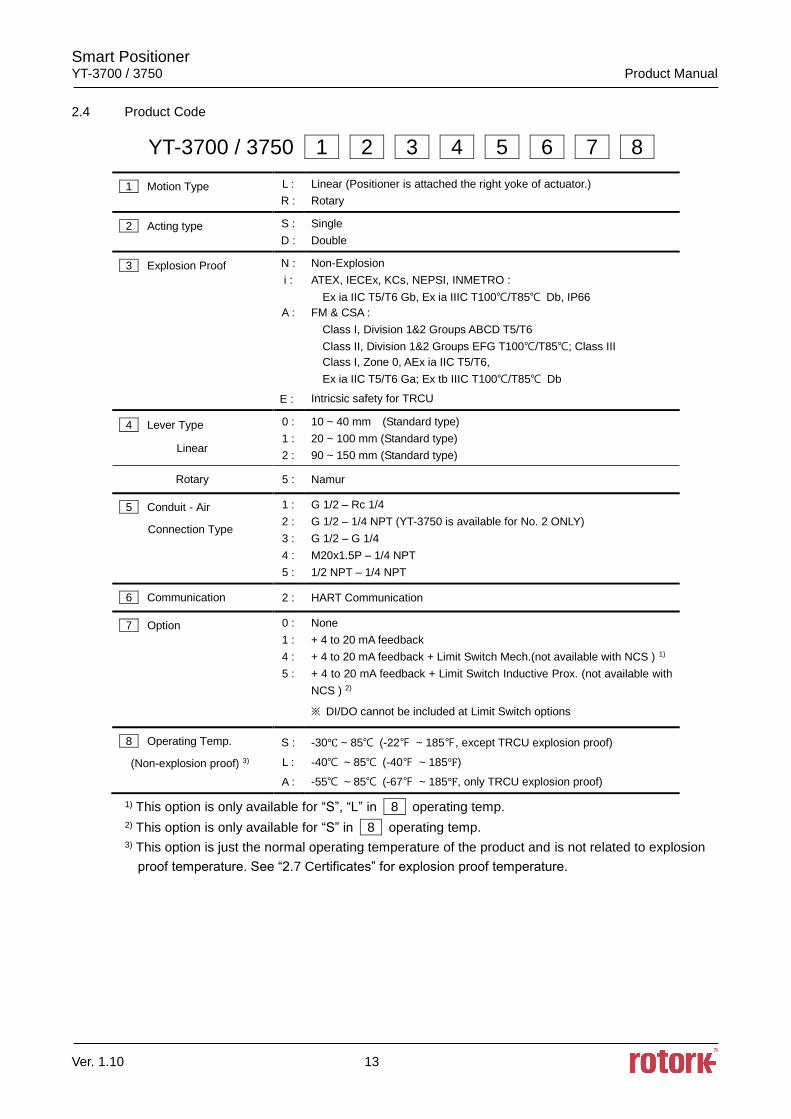
2.4 Product Code
YT-3700 / 3750 1 2 3 4 5 6 7 8
1 Motion Type L :
R :
Linear (Positioner is attached the right yoke of actuator.)
Rotary
2 Acting type S :
D :
Single
Double
3 Explosion Proof N :
i :
A :
E :
Non-Explosion
ATEX, IECEx, KCs, NEPSI, INMETRO :
Ex ia IIC T5/T6 Gb, Ex ia IIIC T100/T85 Db, IP66
FM & CSA :
Class I, Division 1&2 Groups ABCD T5/T6
Class II, Division 1&2 Groups EFG T100/T85; Class III
Class I, Zone 0, AEx ia IIC T5/T6,
Ex ia IIC T5/T6 Ga; Ex tb IIIC T100/T85 Db
Intricsic safety for TRCU
4 Lever Type
Linear
0 :
1 :
2 :
10 ~ 40 mm (Standard type)
20 ~ 100 mm (Standard type)
90 ~ 150 mm (Standard type)
Rotary 5 : Namur
5 Conduit - Air
Connection Type
1 :
2 :
3 :
4 :
5 :
G 1/2 – Rc 1/4
G 1/2 – 1/4 NPT (YT-3750 is available for No. 2 ONLY)
G 1/2 – G 1/4
M20x1.5P – 1/4 NPT
1/2 NPT – 1/4 NPT
6 Communication 2 : HART Communication
7 Option
0 :
1 :
4 :
5 :
None
+ 4 to 20 mA feedback
+ 4 to 20 mA feedback + Limit Switch Mech.(not available with NCS ) 1)
+ 4 to 20 mA feedback + Limit Switch Inductive Prox. (not available with
NCS ) 2)
※ DI/DO cannot be included at Limit Switch options
8 Operating Temp.
(Non-explosion proof) 3)
S :
L :
A :
-30 ~ 85 (-22 ~ 185, except TRCU explosion proof)
-40 ~ 85 (-40 ~ 185)
-55 ~ 85 (-67 ~ 185, only TRCU explosion proof)
1) This option is only available for “S”, “L” in 8 operating temp.
2) This option is only available for “S” in 8 operating temp.
3) This option is just the normal operating temperature of the product and is not related to explosion
proof temperature. See “2.7 Certificates” for explosion proof temperature.
Smart Positioner YT-3700 / 3750 Product Manual
Ver. 1.10 14
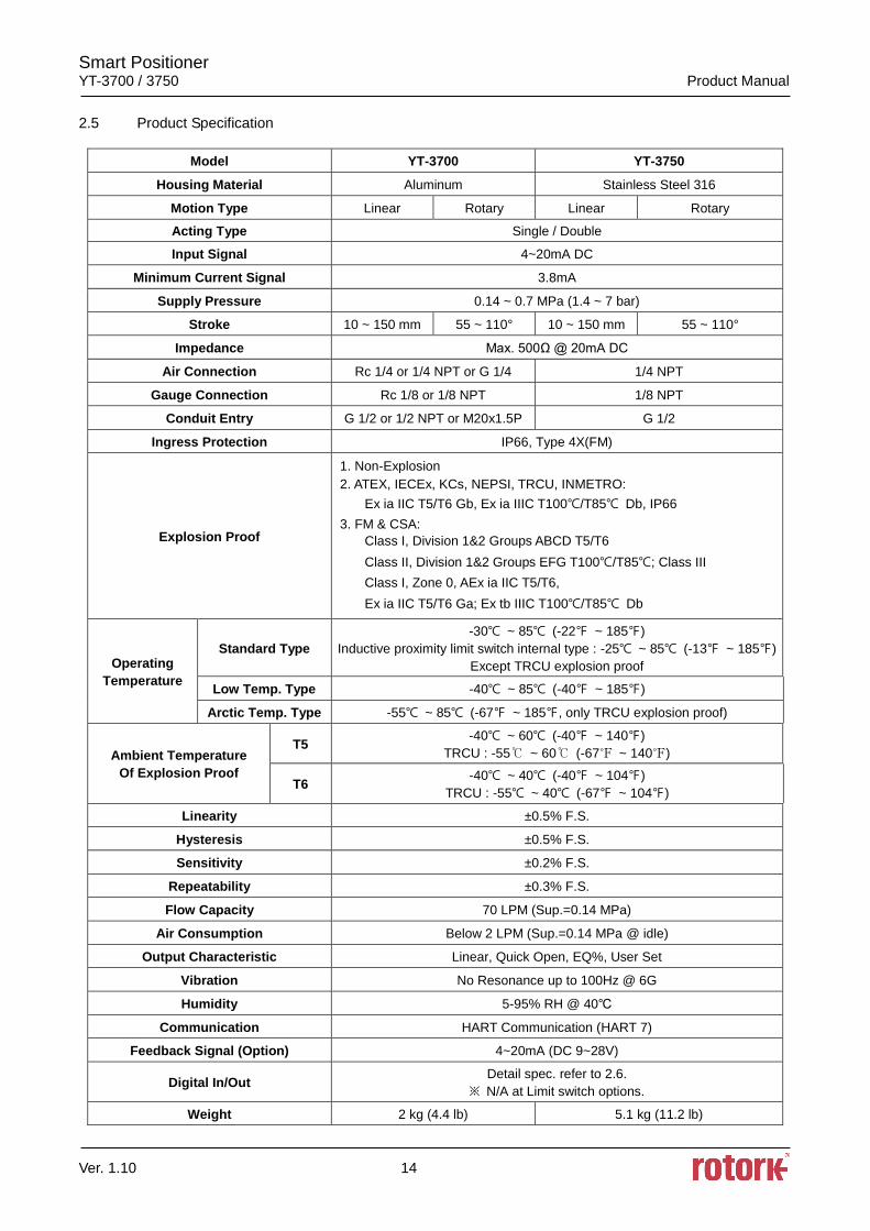
2.5 Product Specification
Model YT-3700 YT-3750
Housing Material Aluminum Stainless Steel 316
Motion Type Linear Rotary Linear Rotary
Acting Type Single / Double
Input Signal 4~20mA DC
Minimum Current Signal 3.8mA
Supply Pressure 0.14 ~ 0.7 MPa (1.4 ~ 7 bar)
Stroke 10 ~ 150 mm 55 ~ 110° 10 ~ 150 mm 55 ~ 110°
Impedance Max. 500Ω @ 20mA DC
Air Connection Rc 1/4 or 1/4 NPT or G 1/4 1/4 NPT
Gauge Connection Rc 1/8 or 1/8 NPT 1/8 NPT
Conduit Entry G 1/2 or 1/2 NPT or M20x1.5P G 1/2
Ingress Protection IP66, Type 4X(FM)
Explosion Proof
1. Non-Explosion
2. ATEX, IECEx, KCs, NEPSI, TRCU, INMETRO:
Ex ia IIC T5/T6 Gb, Ex ia IIIC T100/T85 Db, IP66
3. FM & CSA:
Class I, Division 1&2 Groups ABCD T5/T6
Class II, Division 1&2 Groups EFG T100/T85; Class III
Class I, Zone 0, AEx ia IIC T5/T6,
Ex ia IIC T5/T6 Ga; Ex tb IIIC T100/T85 Db
Operating
Temperature
Standard Type
-30 ~ 85 (-22 ~ 185)
Inductive proximity limit switch internal type : -25 ~ 85 (-13 ~ 185)
Except TRCU explosion proof
Low Temp. Type -40 ~ 85 (-40 ~ 185)
Arctic Temp. Type -55 ~ 85 (-67 ~ 185, only TRCU explosion proof)
Ambient Temperature
Of Explosion Proof
T5 -40 ~ 60 (-40 ~ 140)
TRCU : -55 ~ 60 (-67 ~ 140)
T6 -40 ~ 40 (-40 ~ 104)
TRCU : -55 ~ 40 (-67 ~ 104)
Linearity ±0.5% F.S.
Hysteresis ±0.5% F.S.
Sensitivity ±0.2% F.S.
Repeatability ±0.3% F.S.
Flow Capacity 70 LPM (Sup.=0.14 MPa)
Air Consumption Below 2 LPM (Sup.=0.14 MPa @ idle)
Output Characteristic Linear, Quick Open, EQ%, User Set
Vibration No Resonance up to 100Hz @ 6G
Humidity 5-95% RH @ 40
Communication HART Communication (HART 7)
Feedback Signal (Option) 4~20mA (DC 9~28V)
Digital In/Out Detail spec. refer to 2.6.
※ N/A at Limit switch options.
Weight 2 kg (4.4 lb) 5.1 kg (11.2 lb)
Smart Positioner YT-3700 / 3750 Product Manual
Ver. 1.10 15
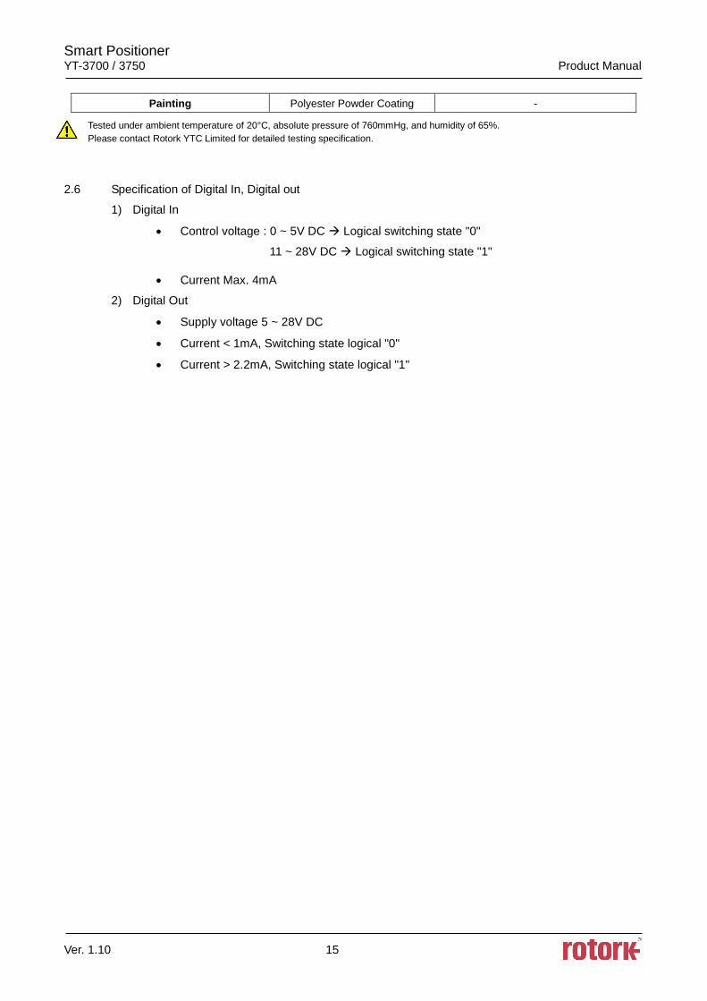
Painting Polyester Powder Coating -
Tested under ambient temperature of 20°C, absolute pressure of 760mmHg, and humidity of 65%.
Please contact Rotork YTC Limited for detailed testing specification.
2.6 Specification of Digital In, Digital out
1) Digital In
• Control voltage : 0 ~ 5V DC Logical switching state "0"
11 ~ 28V DC Logical switching state "1"
• Current Max. 4mA
2) Digital Out
• Supply voltage 5 ~ 28V DC
• Current < 1mA, Switching state logical "0"
• Current > 2.2mA, Switching state logical "1"
Smart Positioner YT-3700 / 3750 Product Manual
Ver. 1.10 16
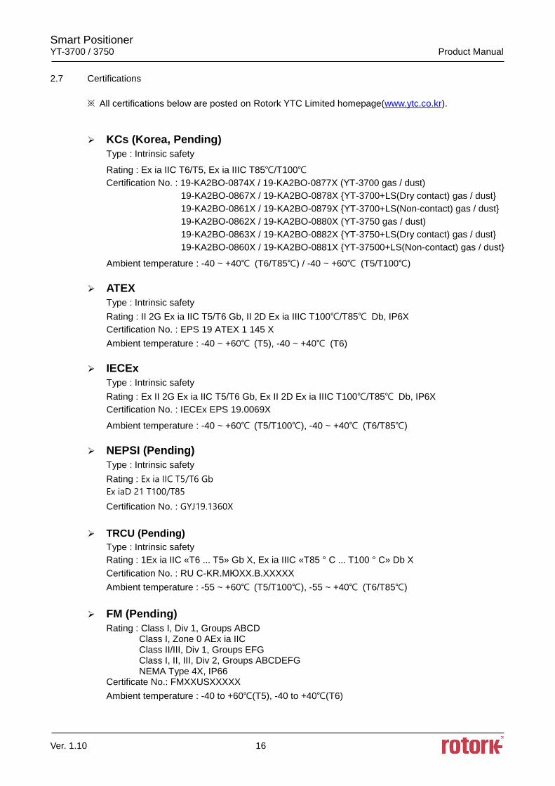
2.7 Certifications
※ All certifications below are posted on Rotork YTC Limited homepage(www.ytc.co.kr).
KCs (Korea, Pending)
Type : Intrinsic safety
Rating : Ex ia IIC T6/T5, Ex ia IIIC T85/T100
Certification No. : 19-KA2BO-0874X / 19-KA2BO-0877X (YT-3700 gas / dust)
19-KA2BO-0867X / 19-KA2BO-0878X YT-3700+LS(Dry contact) gas / dust
19-KA2BO-0861X / 19-KA2BO-0879X YT-3700+LS(Non-contact) gas / dust
19-KA2BO-0862X / 19-KA2BO-0880X (YT-3750 gas / dust)
19-KA2BO-0863X / 19-KA2BO-0882X YT-3750+LS(Dry contact) gas / dust
19-KA2BO-0860X / 19-KA2BO-0881X YT-37500+LS(Non-contact) gas / dust
Ambient temperature : -40 ~ +40 (T6/T85) / -40 ~ +60 (T5/T100)
ATEX
Type : Intrinsic safety
Rating : II 2G Ex ia IIC T5/T6 Gb, II 2D Ex ia IIIC T100/T85 Db, IP6X
Certification No. : EPS 19 ATEX 1 145 X
Ambient temperature : -40 ~ +60 (T5), -40 ~ +40 (T6)
IECEx
Type : Intrinsic safety
Rating : Ex II 2G Ex ia IIC T5/T6 Gb, Ex II 2D Ex ia IIIC T100/T85 Db, IP6X
Certification No. : IECEx EPS 19.0069X
Ambient temperature : -40 ~ +60 (T5/T100), -40 ~ +40 (T6/T85)
NEPSI (Pending)
Type : Intrinsic safety
Rating : Ex ia IIC T5/T6 Gb
Ex iaD 21 T100/T85
Certification No. : GYJ19.1360X
TRCU (Pending)
Type : Intrinsic safety
Rating : 1Ex ia IIC «T6 ... T5» Gb X, Ex ia IIIC «T85 ° C ... T100 ° C» Db X
Certification No. : RU C-KR.MЮXX.B.XXXXX
Ambient temperature : -55 ~ +60 (T5/T100), -55 ~ +40 (T6/T85)
FM (Pending)
Rating : Class I, Div 1, Groups ABCD Class I, Zone 0 AEx ia IIC Class II/III, Div 1, Groups EFG Class I, II, III, Div 2, Groups ABCDEFG NEMA Type 4X, IP66 Certificate No.: FMXXUSXXXXX
Ambient temperature : -40 to +60(T5), -40 to +40(T6)
Smart Positioner YT-3700 / 3750 Product Manual
Ver. 1.10 17
CSA (Pending)
Type : Intrinsic safety
Rating : Class I, Division 1&2 Groups ABCD T5/T6
Class II, Division 1&2 Groups EFG T100/T85
Class III Ex ia IIC T5/T6 Ga
Ex tb IIIC T100/T85 Db
IP66
Certificate No.: CSA XX.XXXXXXXX
Ambient temperature : -40 to +60(T5), -40 to +40(T6)
INMETRO (Brazil)
Type : Intrinsic safety
Rating : Ex ia IIC T5/T6 Gb, Ex ia IIIC T100/T85 Db, IP66
Certification No. : DNV 19.0145 X
Ambient temperature : -40 ~ +60 (T5), -40 ~ +40 (T6)
SIL2 (in a redundant structure up to SIL 3, Pending)
Intended application : Safety function is defined as to move into fail-safe-position, when
signal to positioner is interrupted.
Certification No. : XXX/V XXX.XX/XX
Electromagnetic Compatibility (EMC)
- EMC directive 2014/30/EC from April 2016
- EC Directive for CE conformity marking
- Registration No. : R-R-YT3-YT-3700-01 R-R-YT3-YT-3700LSN-01
Smart Positioner YT-3700 / 3750 Product Manual
Ver. 1.10 18
2.8 Parts and Assembly
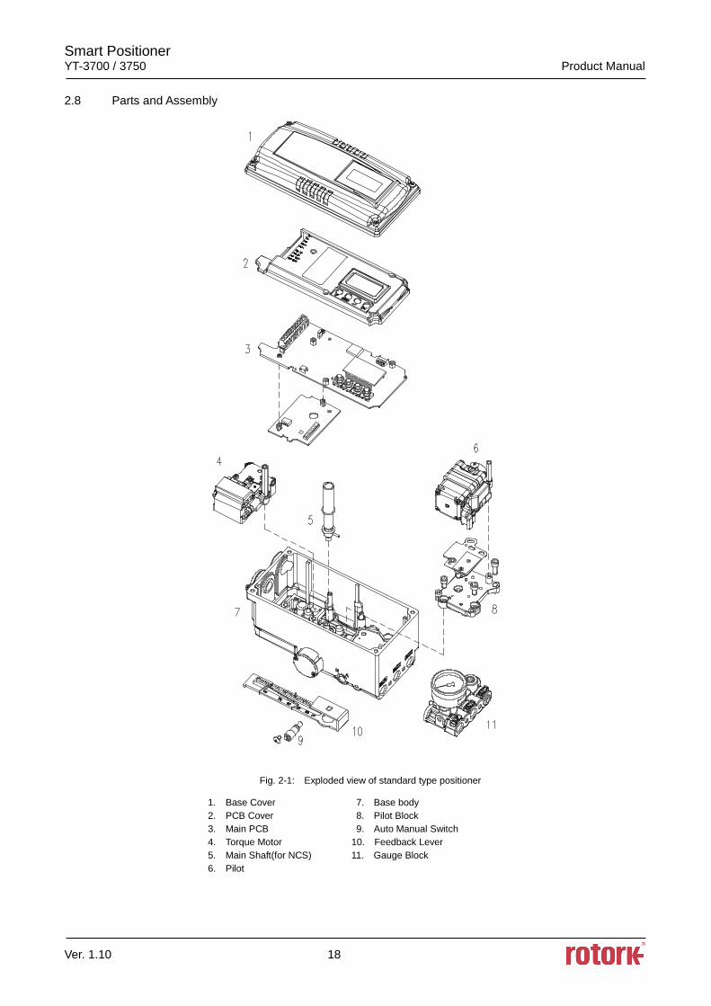
Fig. 2-1: Exploded view of standard type positioner
1. Base Cover 7. Base body
2. PCB Cover 8. Pilot Block
3. Main PCB 9. Auto Manual Switch
4. Torque Motor 10. Feedback Lever
5. Main Shaft(for NCS) 11. Gauge Block
6. Pilot
Smart Positioner YT-3700 / 3750 Product Manual
Ver. 1.10 19
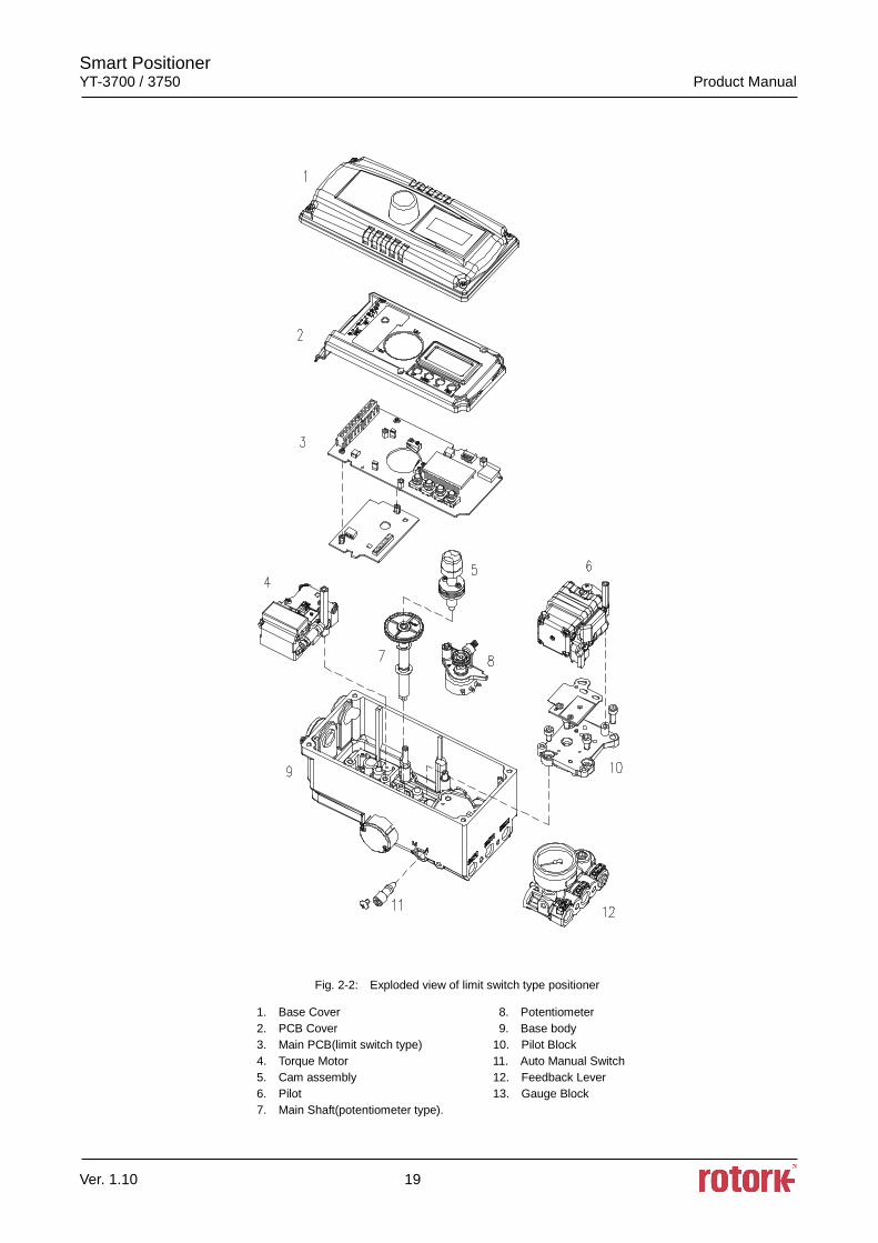
Fig. 2-2: Exploded view of limit switch type positioner
1. Base Cover 8. Potentiometer
2. PCB Cover 9. Base body
3. Main PCB(limit switch type) 10. Pilot Block
4. Torque Motor 11. Auto Manual Switch
5. Cam assembly 12. Feedback Lever
6. Pilot 13. Gauge Block
7. Main Shaft(potentiometer type).
Smart Positioner YT-3700 / 3750 Product Manual
Ver. 1.10 20
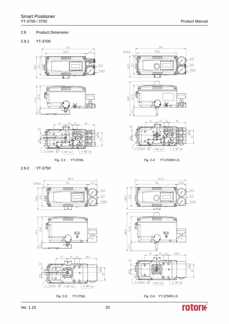
2.9 Product Dimension
2.9.1 YT-3700
Fig. 2-3: YT-3700L Fig. 2-4: YT-3700R+LS
2.9.2 YT-3750
Fig. 2-5: YT-3750L Fig. 2-6: YT-3750R+LS
Smart Positioner YT-3700 / 3750 Product Manual
Ver. 1.10 21
3 Installation
3.1 Safety
When installing a positioner, please ensure to read and follow safety instructions.
Any input or supply pressures to valve, actuator, and / or to other related devices must be turned
off.
Use bypass valve or other supportive equipment to avoid entire system “shut down”.
Ensure there is no remaining pressure in the actuator.
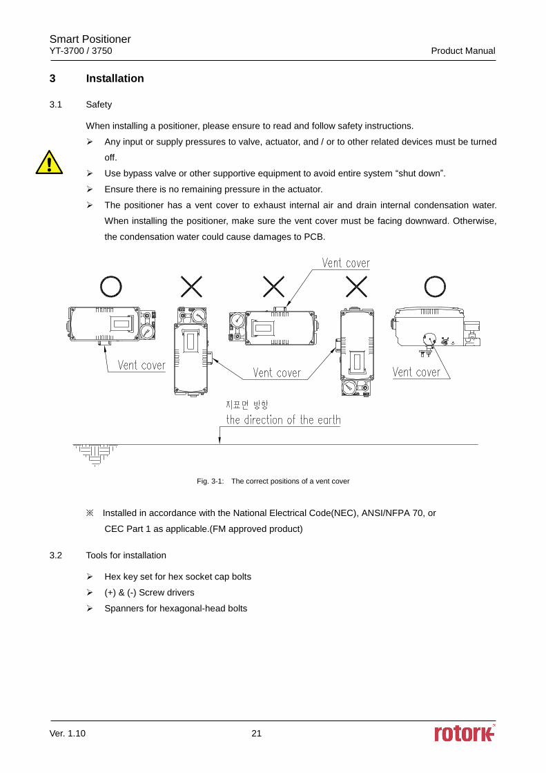
The positioner has a vent cover to exhaust internal air and drain internal condensation water.
When installing the positioner, make sure the vent cover must be facing downward. Otherwise,
the condensation water could cause damages to PCB.
Fig. 3-1: The correct positions of a vent cover
※ Installed in accordance with the National Electrical Code(NEC), ANSI/NFPA 70, or
CEC Part 1 as applicable.(FM approved product)
3.2 Tools for installation
Hex key set for hex socket cap bolts
(+) & (-) Screw drivers
Spanners for hexagonal-head bolts
Smart Positioner YT-3700 / 3750 Product Manual
Ver. 1.10 22
3.3 Linear positioner Installation
Linear positioner should be installed on linear motion valves such as globe or gate type which uses
spring return type diaphragm or piston actuators.
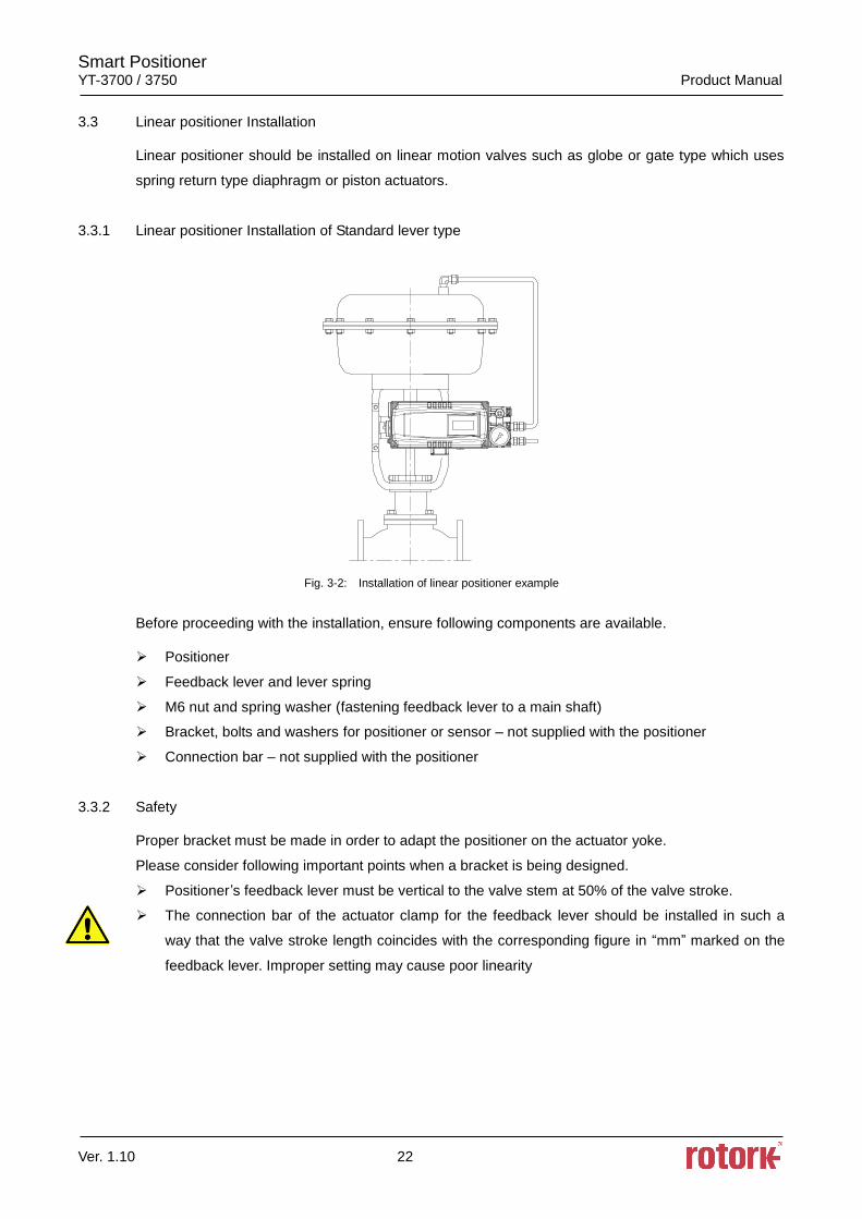
3.3.1 Linear positioner Installation of Standard lever type
Fig. 3-2: Installation of linear positioner example
Before proceeding with the installation, ensure following components are available.
Positioner
Feedback lever and lever spring
M6 nut and spring washer (fastening feedback lever to a main shaft)
Bracket, bolts and washers for positioner or sensor – not supplied with the positioner
Connection bar – not supplied with the positioner
3.3.2 Safety
Proper bracket must be made in order to adapt the positioner on the actuator yoke.
Please consider following important points when a bracket is being designed.
Positioner’s feedback lever must be vertical to the valve stem at 50% of the valve stroke.
The connection bar of the actuator clamp for the feedback lever should be installed in such a
way that the valve stroke length coincides with the corresponding figure in “mm” marked on the
feedback lever. Improper setting may cause poor linearity
Smart Positioner YT-3700 / 3750 Product Manual
Ver. 1.10 23
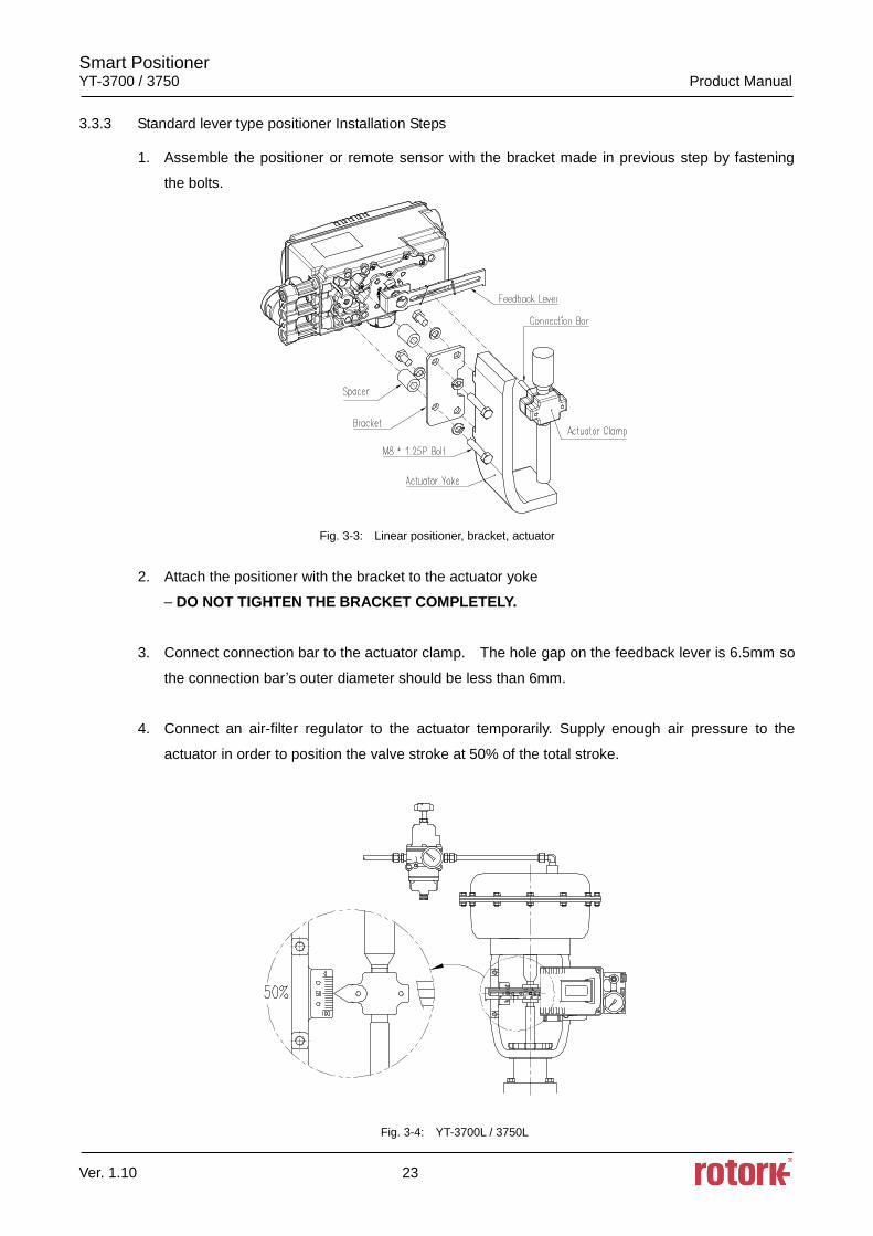
3.3.3 Standard lever type positioner Installation Steps
1. Assemble the positioner or remote sensor with the bracket made in previous step by fastening
the bolts.
Fig. 3-3: Linear positioner, bracket, actuator
2. Attach the positioner with the bracket to the actuator yoke
– DO NOT TIGHTEN THE BRACKET COMPLETELY.
3. Connect connection bar to the actuator clamp. The hole gap on the feedback lever is 6.5mm so
the connection bar’s outer diameter should be less than 6mm.
4. Connect an air-filter regulator to the actuator temporarily. Supply enough air pressure to the
actuator in order to position the valve stroke at 50% of the total stroke.
Fig. 3-4: YT-3700L / 3750L
Smart Positioner YT-3700 / 3750 Product Manual
Ver. 1.10 24
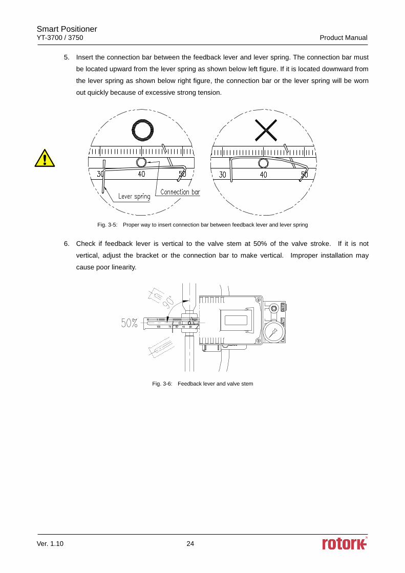
5. Insert the connection bar between the feedback lever and lever spring. The connection bar must
be located upward from the lever spring as shown below left figure. If it is located downward from
the lever spring as shown below right figure, the connection bar or the lever spring will be worn
out quickly because of excessive strong tension.
Fig. 3-5: Proper way to insert connection bar between feedback lever and lever spring
6. Check if feedback lever is vertical to the valve stem at 50% of the valve stroke. If it is not
vertical, adjust the bracket or the connection bar to make vertical. Improper installation may
cause poor linearity.
Fig. 3-6: Feedback lever and valve stem
Smart Positioner YT-3700 / 3750 Product Manual
Ver. 1.10 25
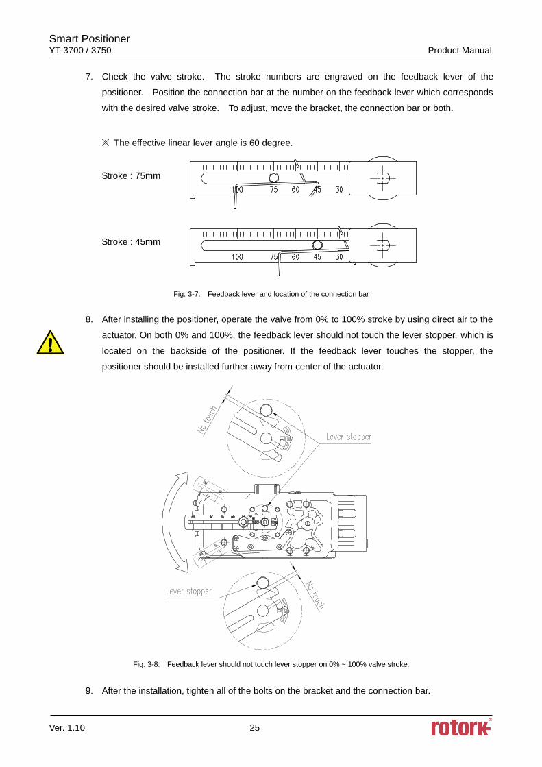
7. Check the valve stroke. The stroke numbers are engraved on the feedback lever of the
positioner. Position the connection bar at the number on the feedback lever which corresponds
with the desired valve stroke. To adjust, move the bracket, the connection bar or both.
※ The effective linear lever angle is 60 degree.
Stroke : 75mm
Stroke : 45mm
Fig. 3-7: Feedback lever and location of the connection bar
8. After installing the positioner, operate the valve from 0% to 100% stroke by using direct air to the
actuator. On both 0% and 100%, the feedback lever should not touch the lever stopper, which is
located on the backside of the positioner. If the feedback lever touches the stopper, the
positioner should be installed further away from center of the actuator.
Fig. 3-8: Feedback lever should not touch lever stopper on 0% ~ 100% valve stroke.
9. After the installation, tighten all of the bolts on the bracket and the connection bar.
Smart Positioner YT-3700 / 3750 Product Manual
Ver. 1.10 26
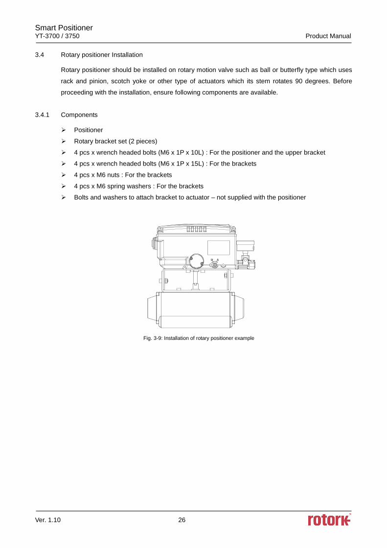
3.4 Rotary positioner Installation
Rotary positioner should be installed on rotary motion valve such as ball or butterfly type which uses
rack and pinion, scotch yoke or other type of actuators which its stem rotates 90 degrees. Before
proceeding with the installation, ensure following components are available.
3.4.1 Components
Positioner
Rotary bracket set (2 pieces)
4 pcs x wrench headed bolts (M6 x 1P x 10L) : For the positioner and the upper bracket
4 pcs x wrench headed bolts (M6 x 1P x 15L) : For the brackets
4 pcs x M6 nuts : For the brackets
4 pcs x M6 spring washers : For the brackets
Bolts and washers to attach bracket to actuator – not supplied with the positioner
Fig. 3-9: Installation of rotary positioner example
Smart Positioner YT-3700 / 3750 Product Manual
Ver. 1.10 27
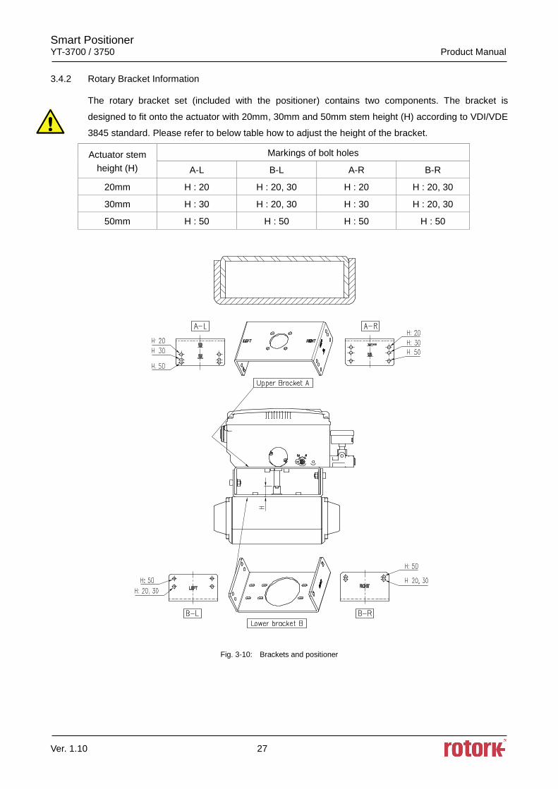
3.4.2 Rotary Bracket Information
The rotary bracket set (included with the positioner) contains two components. The bracket is
designed to fit onto the actuator with 20mm, 30mm and 50mm stem height (H) according to VDI/VDE
3845 standard. Please refer to below table how to adjust the height of the bracket.
Actuator stem
height (H)
Markings of bolt holes
A-L B-L A-R B-R
20mm H : 20 H : 20, 30 H : 20 H : 20, 30
30mm H : 30 H : 20, 30 H : 30 H : 20, 30
50mm H : 50 H : 50 H : 50 H : 50
Fig. 3-10: Brackets and positioner
Smart Positioner YT-3700 / 3750 Product Manual
Ver. 1.10 28
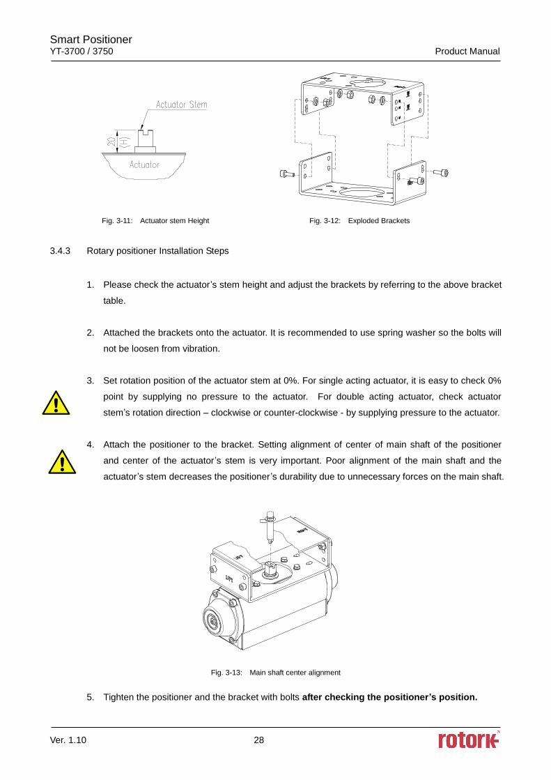
Fig. 3-11: Actuator stem Height Fig. 3-12: Exploded Brackets
3.4.3 Rotary positioner Installation Steps
1. Please check the actuator’s stem height and adjust the brackets by referring to the above bracket
table.
2. Attached the brackets onto the actuator. It is recommended to use spring washer so the bolts will
not be loosen from vibration.
3. Set rotation position of the actuator stem at 0%. For single acting actuator, it is easy to check 0%
point by supplying no pressure to the actuator. For double acting actuator, check actuator
stem’s rotation direction – clockwise or counter-clockwise - by supplying pressure to the actuator.
4. Attach the positioner to the bracket. Setting alignment of center of main shaft of the positioner
and center of the actuator’s stem is very important. Poor alignment of the main shaft and the
actuator’s stem decreases the positioner ’s durability due to unnecessary forces on the main shaft.
Fig. 3-13: Main shaft center alignment
5. Tighten the positioner and the bracket with bolts after checking the positioner’s position.
Smart Positioner YT-3700 / 3750 Product Manual
Ver. 1.10 29
4 Connection - Air
4.1 Safety
Supply pressure should be clean and dry air – avoiding moisture, oil and dust.
Always recommended to use air filter regulator (i.e. YT-200 series).
Rotork YTC Limited has not tested positioner’s operation with any other gases other than
clean air. Please contact Rotork YTC Limited for any questions.
4.2 Supply Pressure Condition
Dry air with dew point of at least 10 lower than ambient temperature.
Avoid from dusty air. Use 5 micron or smaller filter.
Avoid oil.
Comply with ISO 8573-1 or ISA 7.0.01.
Supply pressure range is 0.14 ~0.7 MPa (1.4 ~ 7 bar)
Set air filter regulator’s pressure level 10% higher than actuator’s spring range pressure.
4.3 Piping Condition
Ensure inside of pipe is clean of obstructions.
Do not use pipeline that is squeezed or shows any type of damamges.
Pipeline should have more than 6mm of inner diameter (10mm outer diameter) to maintain flow
rate.
The length of pipeline system should not be extremely long. Longer pipeline system may affect
flow rate due to the friction inside of the pipeline.
Smart Positioner YT-3700 / 3750 Product Manual
Ver. 1.10 30
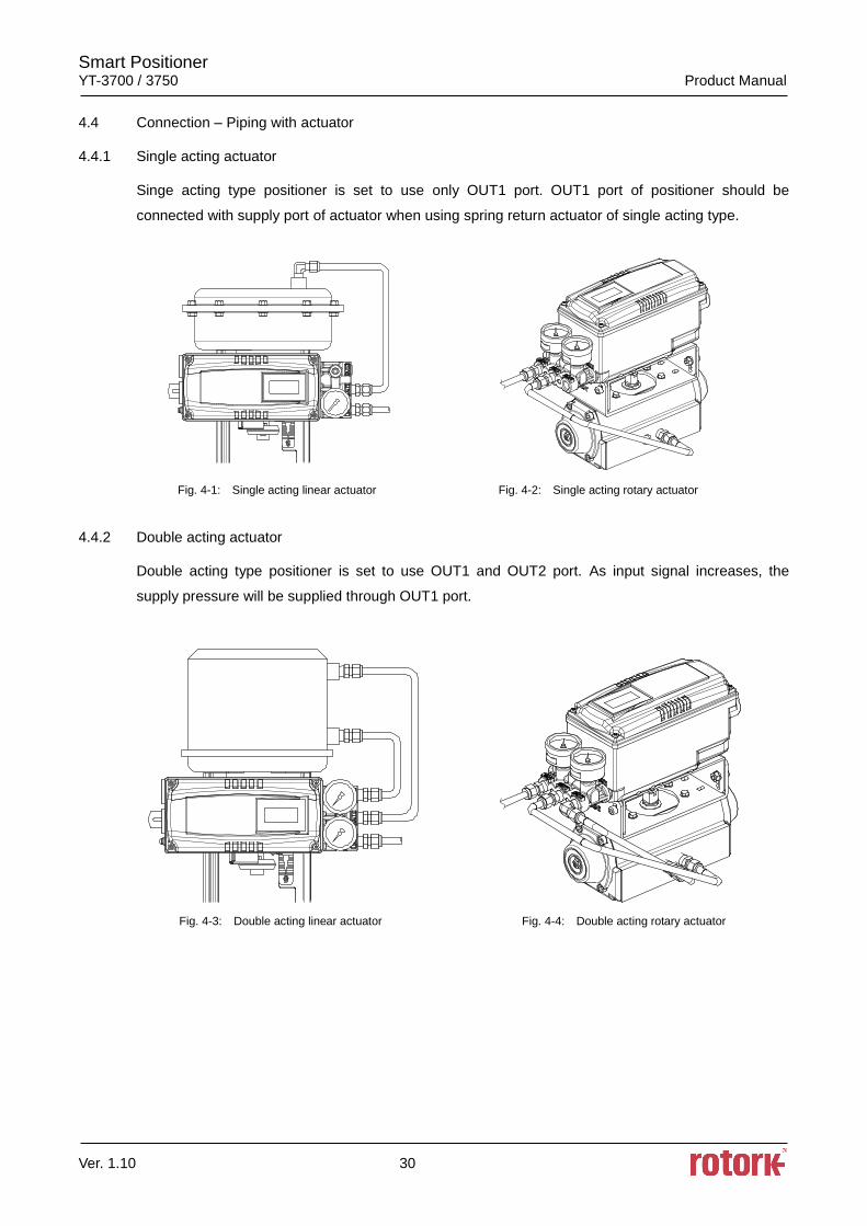
4.4 Connection – Piping with actuator
4.4.1 Single acting actuator
Singe acting type positioner is set to use only OUT1 port. OUT1 port of positioner should be
connected with supply port of actuator when using spring return actuator of single acting type.
Fig. 4-1: Single acting linear actuator Fig. 4-2: Single acting rotary actuator
4.4.2 Double acting actuator
Double acting type positioner is set to use OUT1 and OUT2 port. As input signal increases, the
supply pressure will be supplied through OUT1 port.
Fig. 4-3: Double acting linear actuator Fig. 4-4: Double acting rotary actuator
Smart Positioner YT-3700 / 3750 Product Manual
Ver. 1.10 31
5 Connection – Power
5.1 Safety
There are two conduit entries on the product. See “2.4 Product Code” for conduit entry threads.
Before connecting terminal, ensure that the power is off completely.
Please use ring terminal to protect against vibration or any other external impact.
Positioner usually uses 4~20mA DC. Minimum ampere of input signal is 3.8 mA but maximum
ampere of input signal should be 24mA or under.
Compliance voltage of current source must be Min. 10V and Max. 28V. If the length of the supply
cable between the current source and the positioner is long, or if there is a filter or safety barrier,
then consider using a current source which could supply higher Compliance voltage.
Positioner with PTM options must be supplied with 9~28V DC separately. For mechanical limit
switch option, separate 12~30V DC must be supplied. For inductive proximity limit switch option,
separate 8.2V DC must be supplied.
DO NOT connect Voltage source (9~28V DC) to Input (4~20mA DC) terminal (IN+, IN-) as it will
cause PCB failure.
Positioner should be grounded.
Please use twisted cable with conductor section are 1.25mm2 and that is suitable for 600V
(complying with the conductor table of NEC Article 310). The outer diameter of the cable should
be between 6.35 ~ 10mm. Use shield wire to protect against electro-magnetic field and noise.
Please do not install the cable near high noise equipment, such as high-capacity transformer or
motor.
Please ensure that keep away magnetic materials from a product. It may cause malfunction. For
a magnetic screwdriver, It must be away more than 30cm from a product cover.
Smart Positioner YT-3700 / 3750 Product Manual
Ver. 1.10 32
5.2 Connection
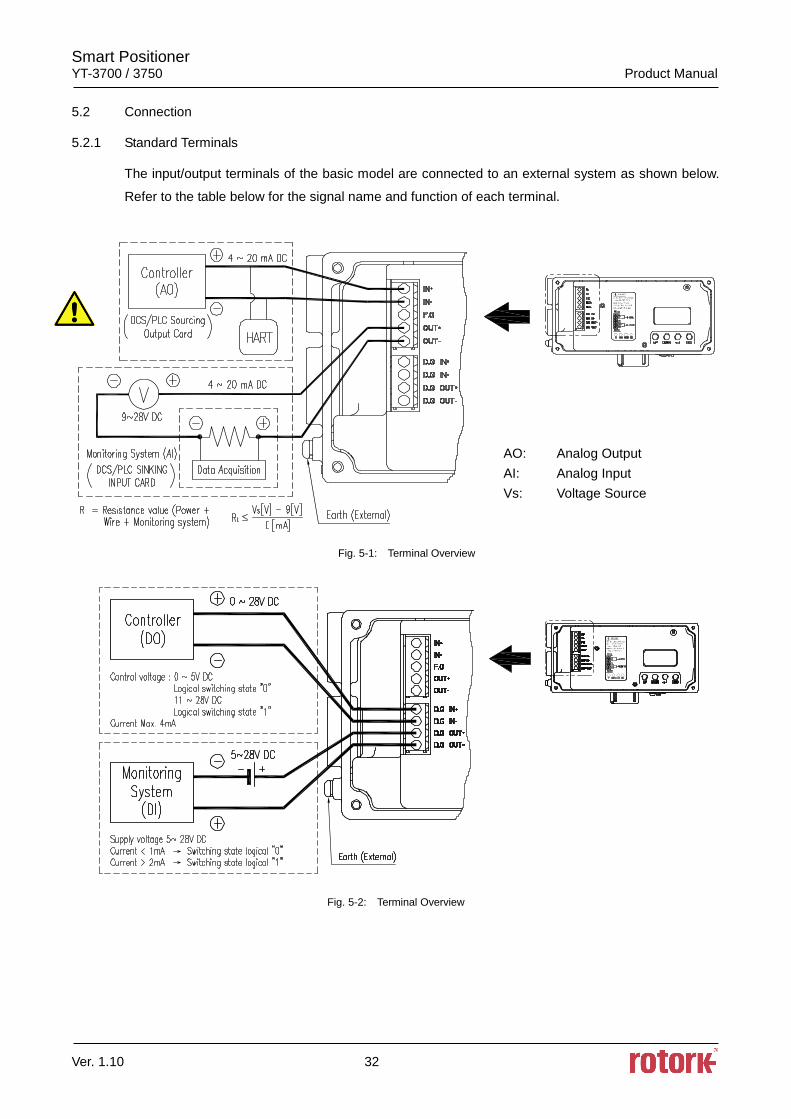
5.2.1 Standard Terminals
The input/output terminals of the basic model are connected to an external system as shown below.
Refer to the table below for the signal name and function of each terminal.
Fig. 5-1: Terminal Overview
Fig. 5-2: Terminal Overview
AO: Analog Output
AI: Analog Input
Vs: Voltage Source
Smart Positioner YT-3700 / 3750 Product Manual
Ver. 1.10 33
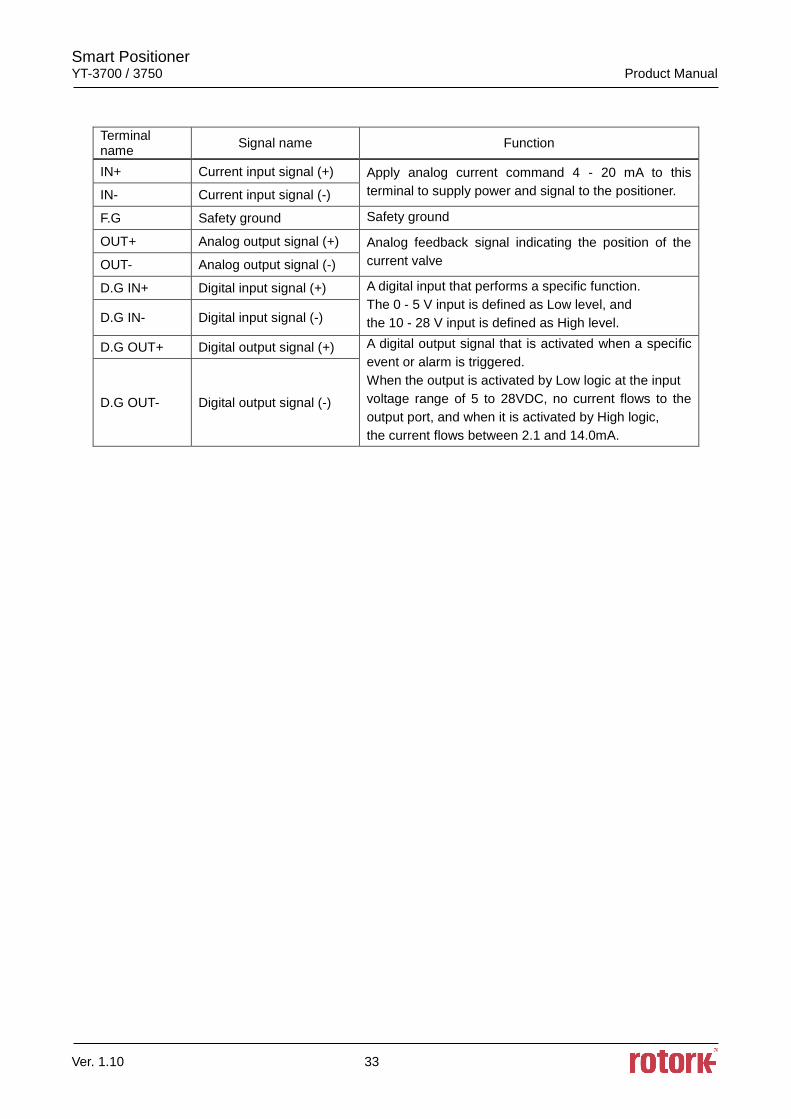
Terminal name
Signal name Function
IN+ Current input signal (+) Apply analog current command 4 - 20 mA to this
terminal to supply power and signal to the positioner. IN- Current input signal (-)
F.G Safety ground Safety ground
OUT+ Analog output signal (+) Analog feedback signal indicating the position of the
current valve OUT- Analog output signal (-)
D.G IN+ Digital input signal (+) A digital input that performs a specific function.
The 0 - 5 V input is defined as Low level, and
the 10 - 28 V input is defined as High level. D.G IN- Digital input signal (-)
D.G OUT+ Digital output signal (+) A digital output signal that is activated when a specific
event or alarm is triggered.
When the output is activated by Low logic at the input
voltage range of 5 to 28VDC, no current flows to the
output port, and when it is activated by High logic,
the current flows between 2.1 and 14.0mA.
D.G OUT- Digital output signal (-)
Smart Positioner YT-3700 / 3750 Product Manual
Ver. 1.10 34
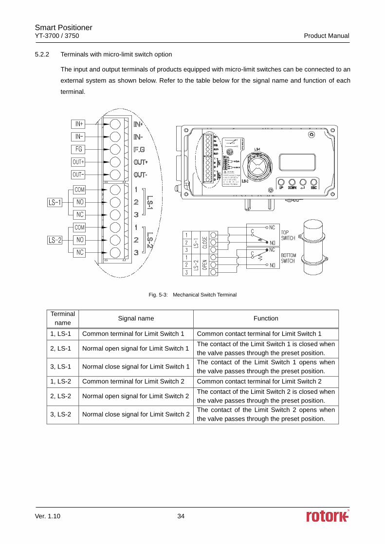
5.2.2 Terminals with micro-limit switch option
The input and output terminals of products equipped with micro-limit switches can be connected to an
external system as shown below. Refer to the table below for the signal name and function of each
terminal.
Fig. 5-3: Mechanical Switch Terminal
Terminal
name Signal name Function
1, LS-1 Common terminal for Limit Switch 1 Common contact terminal for Limit Switch 1
2, LS-1 Normal open signal for Limit Switch 1 The contact of the Limit Switch 1 is closed when
the valve passes through the preset position.
3, LS-1 Normal close signal for Limit Switch 1 The contact of the Limit Switch 1 opens when
the valve passes through the preset position.
1, LS-2 Common terminal for Limit Switch 2 Common contact terminal for Limit Switch 2
2, LS-2 Normal open signal for Limit Switch 2 The contact of the Limit Switch 2 is closed when
the valve passes through the preset position.
3, LS-2 Normal close signal for Limit Switch 2 The contact of the Limit Switch 2 opens when
the valve passes through the preset position.
Smart Positioner YT-3700 / 3750 Product Manual
Ver. 1.10 35
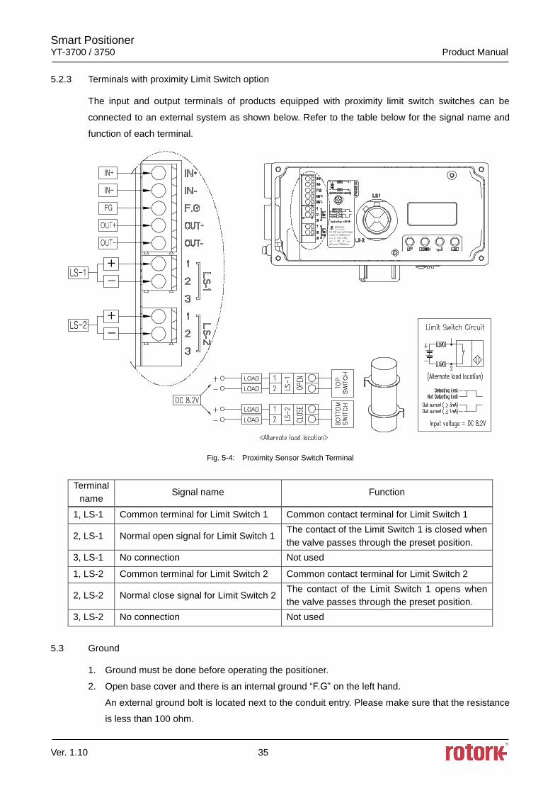
5.2.3 Terminals with proximity Limit Switch option
The input and output terminals of products equipped with proximity limit switch switches can be
connected to an external system as shown below. Refer to the table below for the signal name and
function of each terminal.
Fig. 5-4: Proximity Sensor Switch Terminal
Terminal
name Signal name Function
1, LS-1 Common terminal for Limit Switch 1 Common contact terminal for Limit Switch 1
2, LS-1 Normal open signal for Limit Switch 1 The contact of the Limit Switch 1 is closed when
the valve passes through the preset position.
3, LS-1 No connection Not used
1, LS-2 Common terminal for Limit Switch 2 Common contact terminal for Limit Switch 2
2, LS-2 Normal close signal for Limit Switch 2 The contact of the Limit Switch 1 opens when
the valve passes through the preset position.
3, LS-2 No connection Not used
5.3 Ground
1. Ground must be done before operating the positioner.
2. Open base cover and there is an internal ground “F.G” on the left hand.
An external ground bolt is located next to the conduit entry. Please make sure that the resistance
is less than 100 ohm.
Smart Positioner YT-3700 / 3750 Product Manual
Ver. 1.10 36
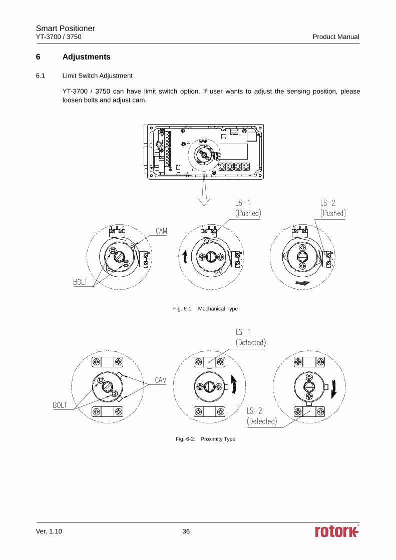
6 Adjustments
6.1 Limit Switch Adjustment
YT-3700 / 3750 can have limit switch option. If user wants to adjust the sensing position, please
loosen bolts and adjust cam.
Fig. 6-1: Mechanical Type
Fig. 6-2: Proximity Type
Smart Positioner YT-3700 / 3750 Product Manual
Ver. 1.10 37
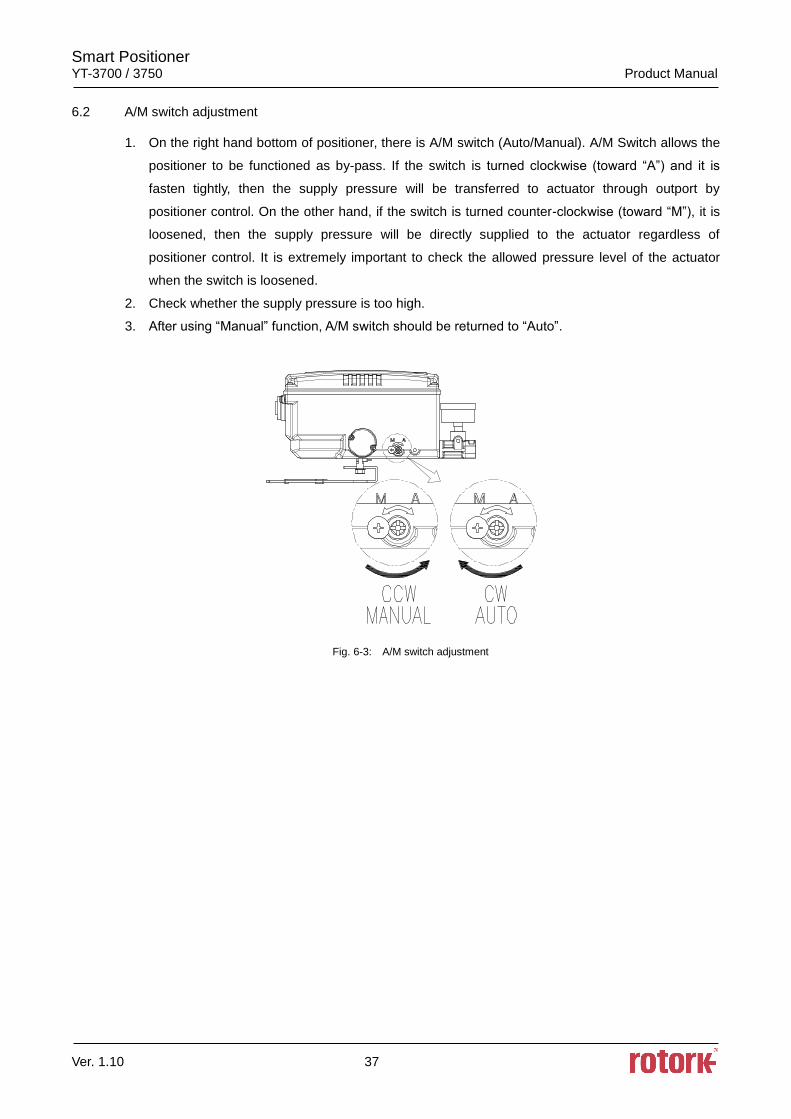
6.2 A/M switch adjustment
1. On the right hand bottom of positioner, there is A/M switch (Auto/Manual). A/M Switch allows the
positioner to be functioned as by-pass. If the switch is turned clockwise (toward “A”) and it is
fasten tightly, then the supply pressure will be transferred to actuator through outport by
positioner control. On the other hand, if the switch is turned counter-clockwise (toward “M”), it is
loosened, then the supply pressure will be directly supplied to the actuator regardless of
positioner control. It is extremely important to check the allowed pressure level of the actuator
when the switch is loosened.
2. Check whether the supply pressure is too high.
3. After using “Manual” function, A/M switch should be returned to “Auto”.
Fig. 6-3: A/M switch adjustment
Smart Positioner YT-3700 / 3750 Product Manual
Ver. 1.10 38
6.3 Orifice Installment
Hunting can be occurred when the actuator ’s volume is too small. In order to prevent hunting, orifice
can be used.
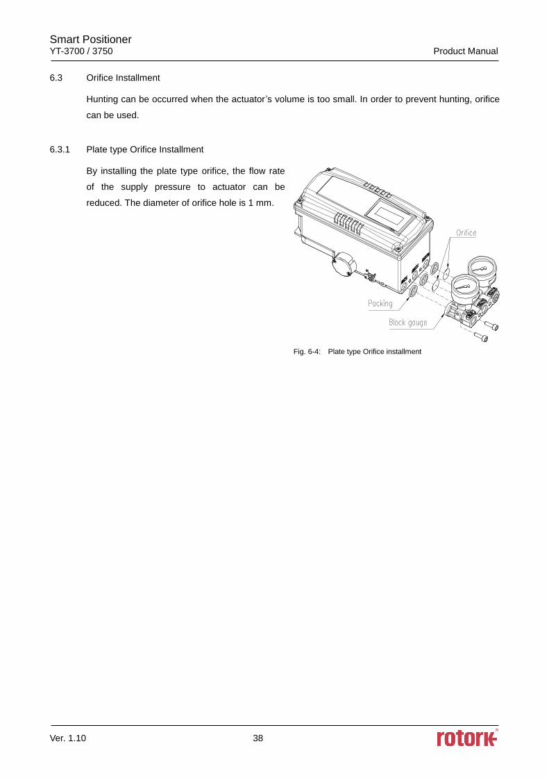
6.3.1 Plate type Orifice Installment
By installing the plate type orifice, the flow rate
of the supply pressure to actuator can be
reduced. The diameter of orifice hole is 1 mm.
Fig. 6-4: Plate type Orifice installment
Smart Positioner YT-3700 / 3750 Product Manual
Ver. 1.10 39
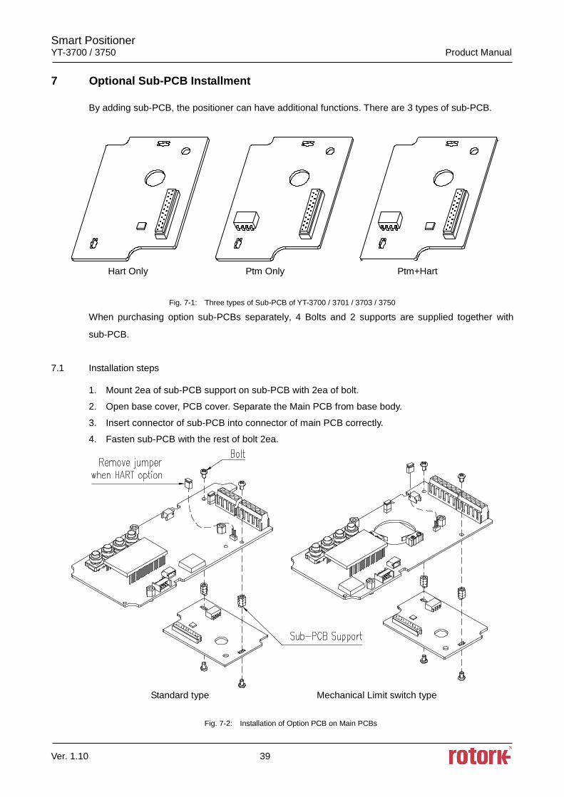
7 Optional Sub-PCB Installment
By adding sub-PCB, the positioner can have additional functions. There are 3 types of sub-PCB.
Hart Only Ptm Only Ptm+Hart
Fig. 7-1: Three types of Sub-PCB of YT-3700 / 3701 / 3703 / 3750
When purchasing option sub-PCBs separately, 4 Bolts and 2 supports are supplied together with
sub-PCB.
7.1 Installation steps
1. Mount 2ea of sub-PCB support on sub-PCB with 2ea of bolt.
2. Open base cover, PCB cover. Separate the Main PCB from base body.
3. Insert connector of sub-PCB into connector of main PCB correctly.
4. Fasten sub-PCB with the rest of bolt 2ea.
Standard type Mechanical Limit switch type
Fig. 7-2: Installation of Option PCB on Main PCBs
Smart Positioner YT-3700 / 3750 Product Manual
Ver. 1.10 40
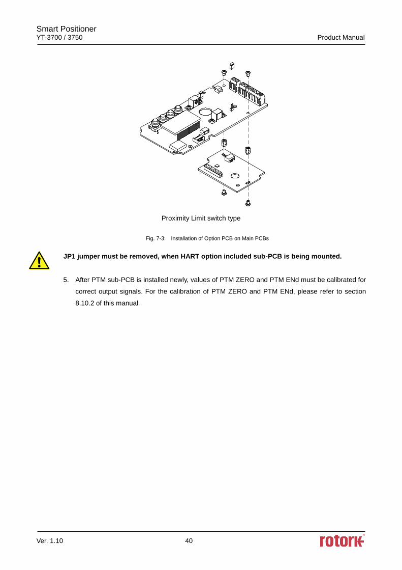
Proximity Limit switch type
Fig. 7-3: Installation of Option PCB on Main PCBs
JP1 jumper must be removed, when HART option included sub-PCB is being mounted.
5. After PTM sub-PCB is installed newly, values of PTM ZERO and PTM ENd must be calibrated for
correct output signals. For the calibration of PTM ZERO and PTM ENd, please refer to section
8.10.2 of this manual.
Smart Positioner YT-3700 / 3750 Product Manual
Ver. 1.10 41
8 Auto Calibration and PCB Operation
8.1 Warning
Following process will operate valve and actuator. Make sure to disconnect the Valve from
the system prior to the automatic calibration (AutoCal) to prevent any disruption of the
process since this operation shall move the Valve and Actuator.
8.2 LCD display and buttons
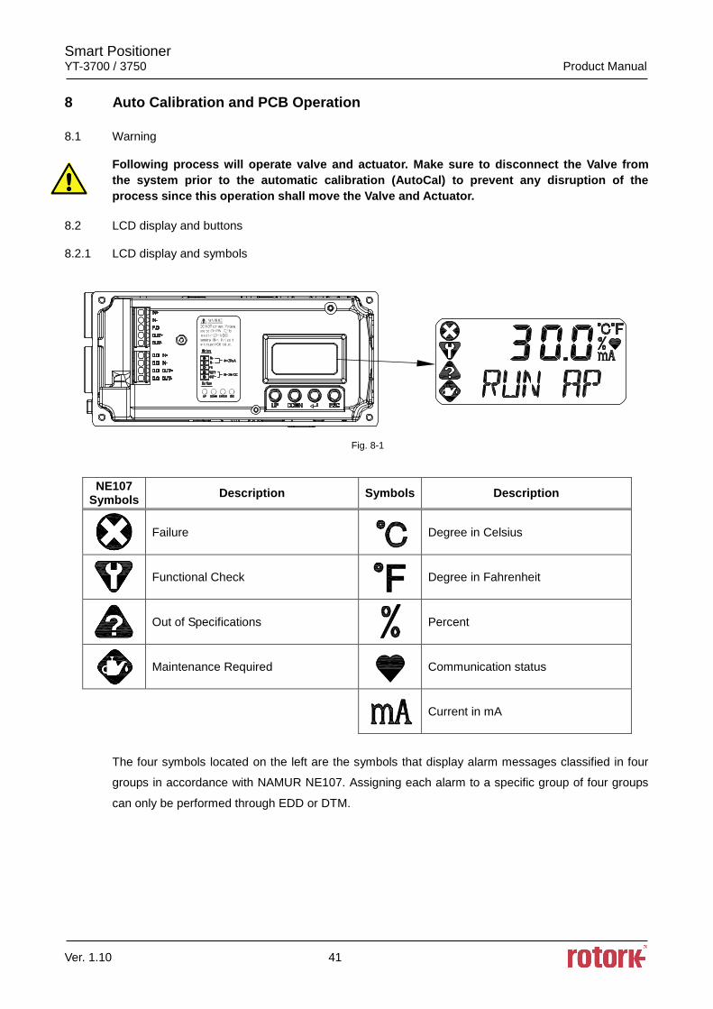
8.2.1 LCD display and symbols
Fig. 8-1
NE107 Symbols
Description Symbols Description
Failure
Degree in Celsius
Functional Check
Degree in Fahrenheit
Out of Specifications
Percent
Maintenance Required
Communication status
Current in mA
The four symbols located on the left are the symbols that display alarm messages classified in four
groups in accordance with NAMUR NE107. Assigning each alarm to a specific group of four groups
can only be performed through EDD or DTM.
Smart Positioner YT-3700 / 3750 Product Manual
Ver. 1.10 42
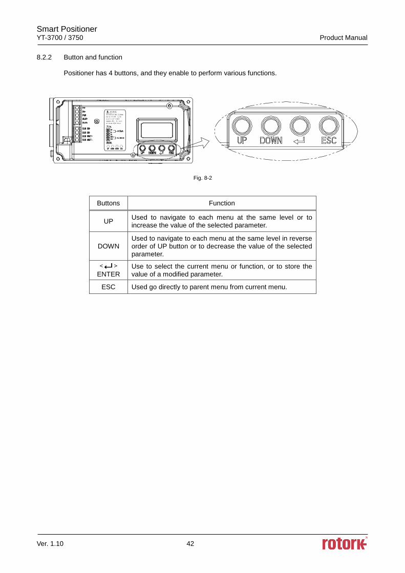
8.2.2 Button and function
Positioner has 4 buttons, and they enable to perform various functions.
Fig. 8-2
Buttons Function
UP Used to navigate to each menu at the same level or to increase the value of the selected parameter.
DOWN Used to navigate to each menu at the same level in reverse order of UP button or to decrease the value of the selected parameter.
ENTER
Use to select the current menu or function, or to store the value of a modified parameter.
ESC Used go directly to parent menu from current menu.
Smart Positioner YT-3700 / 3750 Product Manual
Ver. 1.10 43
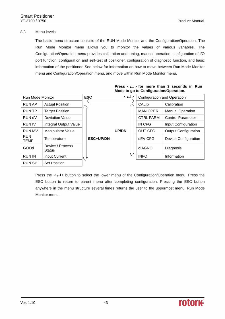
8.3 Menu levels
The basic menu structure consists of the RUN Mode Monitor and the Configuration/Operation. The
Run Mode Monitor menu allows you to monitor the values of various variables. The
Configuration/Operation menu provides calibration and tuning, manual operation, configuration of I/O
port function, configuration and self-test of positioner, configuration of diagnostic function, and basic
information of the positioner. See below for information on how to move between Run Mode Monitor
menu and Configuration/Operation menu, and move within Run Mode Monitor menu.
Press for more than 3 seconds in Run Mode to go to Configuration/Operation.
Run Mode Monitor ESC Configuration and Operation
RUN AP Actual Position CALIb Calibration
RUN TP Target Position MAN OPER Manual Operation
RUN dV Deviation Value CTRL PARM Control Parameter
RUN IV Integral Output Value IN CFG Input Configuration
RUN MV Manipulator Value UP/DN OUT CFG Output Configuration
RUN TEMP
Temperature ESC+UP/DN dEV CFG Device Configuration
GOOd Device / Process Status
dIAGNO Diagnosis
RUN IN Input Current INFO Information
RUN SP Set Position
Press the button to select the lower menu of the Configuration/Operation menu. Press the
ESC button to return to parent menu after completing configuration. Pressing the ESC button
anywhere in the menu structure several times returns the user to the uppermost menu, Run Mode
Monitor menu.
Smart Positioner YT-3700 / 3750 Product Manual
Ver. 1.10 44
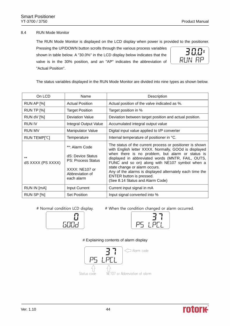
8.4 RUN Mode Monitor
The RUN Mode Monitor is displayed on the LCD display when power is provided to the positioner.
Pressing the UP/DOWN button scrolls through the various process variables
shown in table below. A "30.0%" in the LCD display below indicates that the
valve is in the 30% position, and an "AP" indicates the abbreviation of
"Actual Position".
The status variables displayed in the RUN Mode Monitor are divided into nine types as shown below.
On LCD Name Description
RUN AP [%] Actual Position Actual position of the valve indicated as %.
RUN TP [%] Target Position Target position in %
RUN dV [%] Deviation Value Deviation between target position and actual position.
RUN IV Integral Output Value Accumulated integral output value
RUN MV Manipulator Value Digital input value applied to I/P converter
RUN TEMP[] Temperature Internal temperature of positioner in °C.
** dS XXXX (PS XXXX)
**: Alarm Code dS: Device Status PS: Process Status XXXX: NE107 or Abbreviation of each alarm
The status of the current process or positioner is shown with English letter XXXX. Normally, GOOd is displayed when there is no problem, but alarm or status is displayed in abbreviated words (MNTR, FAIL, OUTS, FUNC and so on) along with NE107 symbol when a state change or alarm occurs. Any of the alarms is displayed alternately each time the ENTER button is pressed. (See 8.14 Status and Alarm Code)
RUN IN [mA] Input Current Current input signal in mA
RUN SP [%] Set Position Input signal converted into %
# Normal condition LCD display. # When the condition changed or alarm occurred.
# Explaining contents of alarm display
Smart Positioner YT-3700 / 3750 Product Manual
Ver. 1.10 45
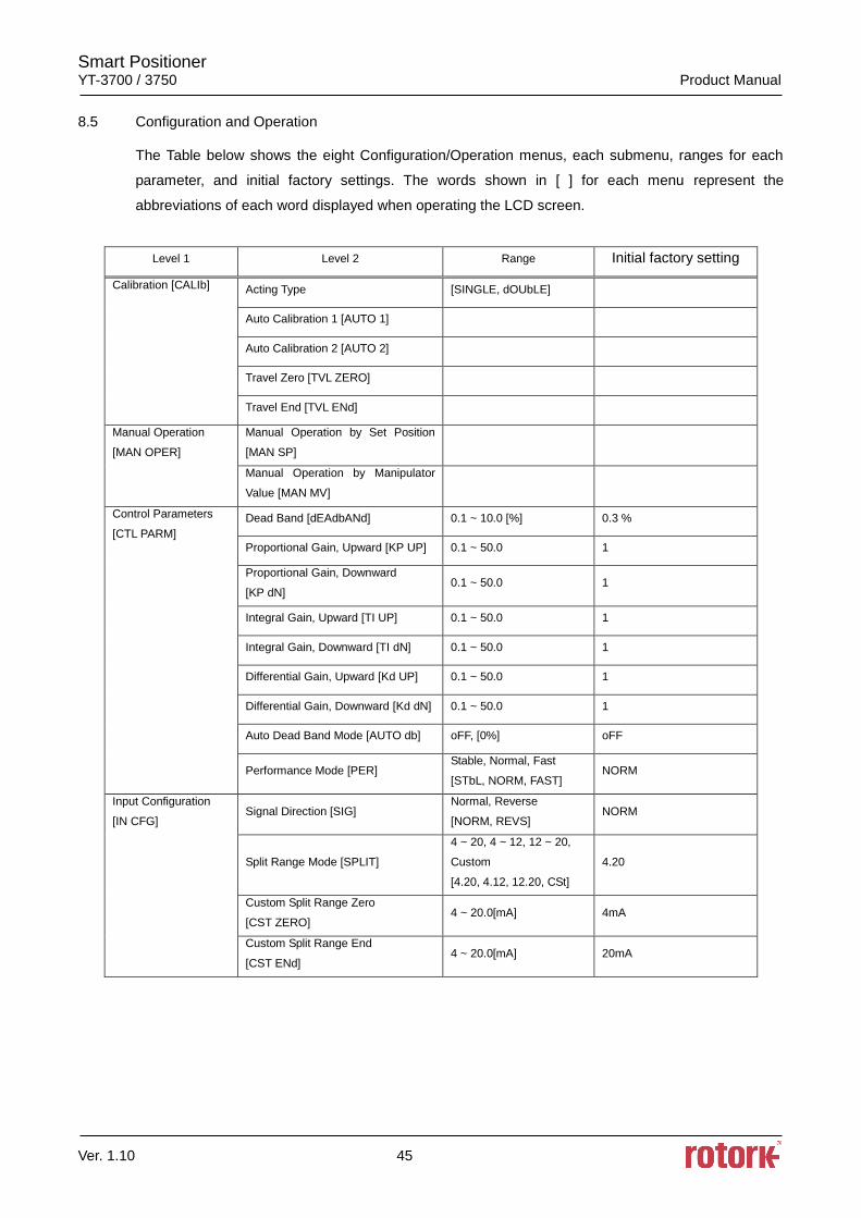
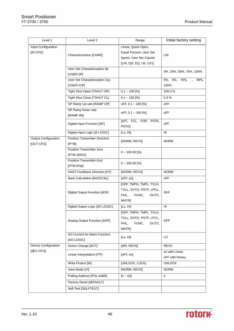
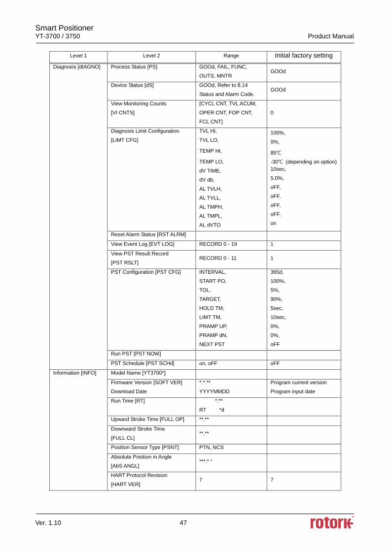
8.5 Configuration and Operation
The Table below shows the eight Configuration/Operation menus, each submenu, ranges for each
parameter, and initial factory settings. The words shown in [ ] for each menu represent the
abbreviations of each word displayed when operating the LCD screen.
Level 1 Level 2 Range Initial factory setting
Calibration [CALIb] Acting Type [SINGLE, dOUbLE]
Auto Calibration 1 [AUTO 1]
Auto Calibration 2 [AUTO 2]
Travel Zero [TVL ZERO]
Travel End [TVL ENd]
Manual Operation
[MAN OPER]
Manual Operation by Set Position
[MAN SP]
Manual Operation by Manipulator
Value [MAN MV]
Control Parameters
[CTL PARM]
Dead Band [dEAdbANd] 0.1 ~ 10.0 [%] 0.3 %
Proportional Gain, Upward [KP UP] 0.1 ~ 50.0 1
Proportional Gain, Downward
[KP dN] 0.1 ~ 50.0 1
Integral Gain, Upward [TI UP] 0.1 ~ 50.0 1
Integral Gain, Downward [TI dN] 0.1 ~ 50.0 1
Differential Gain, Upward [Kd UP] 0.1 ~ 50.0 1
Differential Gain, Downward [Kd dN] 0.1 ~ 50.0 1
Auto Dead Band Mode [AUTO db] oFF, [0%] oFF
Performance Mode [PER] Stable, Normal, Fast
[STbL, NORM, FAST] NORM
Input Configuration
[IN CFG] Signal Direction [SIG]
Normal, Reverse
[NORM, REVS] NORM
Split Range Mode [SPLIT]
4 ~ 20, 4 ~ 12, 12 ~ 20,
Custom
[4.20, 4.12, 12.20, CSt]
4.20
Custom Split Range Zero
[CST ZERO] 4 ~ 20.0[mA] 4mA
Custom Split Range End
[CST ENd] 4 ~ 20.0[mA] 20mA
Smart Positioner YT-3700 / 3750 Product Manual
Ver. 1.10 46
Level 1 Level 2 Range Initial factory setting
Input Configuration
[IN CFG] Characterization [CHAR]
Linear, Quick Open,
Equal Percent, User Set
5point, User Set 21point
[LIN, QO, EQ, U5, U21]
LIN
User Set Characterization 5p
[USER 5P] 0%, 25%, 50%, 75%, 100%
User Set Characterization 21p
[USER 21P]
0%, 5%, 10%, … 95%,
100%
Tight Shut Open [TSHUT OP] 0.1 ~ 100 [%] 100.0 %
Tight Shut Close [TSHUT CL] 0.1 ~ 100 [%] 0.3 %
SP Ramp Up rate [RAMP UP] oFF, 0.1 ~ 100 [%] oFF
SP Ramp Down rate
[RAMP dN] oFF, 0.1 ~ 100 [%] oFF
Digital Input Function [dIF] [oFF, FCL, FOP, PSTA,
PSTO] oFF
Digital Input Logic [dI LOGIC] [Lo, HI] HI
Output Configuration
[OUT CFG]
Position Transmitter Direction
[PTM] [NORM, REVS] NORM
Position Transmitter Zero
[PTM ZERO] 0 ~ 100.00 [%]
Position Transmitter End
[PTM ENd] 0 ~ 100.00 [%]
HART Feedback Direction [HT] [NORM, REVS] NORM
Back Calculation [bACKCAL] [oFF, on] oFF
Digital Output Function [dOF]
[OFF, TMPH, TMPL, TVLH,
TVLL, DVTO, PSTF, LPCL,
FAIL, FUNC, OUTS,
MNTR]
OFF
Digital Output Logic [dO LOGIC] [Lo, HI] HI
Analog Output Function [AOF]
[OFF, TMPH, TMPL, TVLH,
TVLL, DVTO, PSTF, LPCL,
FAIL, FUNC, OUTS,
MNTR]
OFF
AO Current for Alarm Function
[AO LOGIC] [Lo, HI] LO
Device Configuration
[dEV CFG]
Action Change [ACT] [dIR, REVS] REVS
Linear Interpolation [ITP] [oFF, on] on with Linear
oFF with Rotary
Write Protect [W] [UNLOCK, LOCK] UNLOCK
View Mode [VI] [NORM, REVS] NORM
Polling Address [POL AddR] [0 ~ 63] 0
Factory Reset [dEFAULT]
Self-Test [SELFTEST]
Smart Positioner YT-3700 / 3750 Product Manual
Ver. 1.10 47
Level 1 Level 2 Range Initial factory setting
Diagnosis [dIAGNO] Process Status [PS] GOOd, FAIL, FUNC,
OUTS, MNTR GOOd
Device Status [dS] GOOd, Refer to 8.14
Status and Alarm Code. GOOd
View Monitoring Counts
[VI CNTS]
[CYCL CNT, TVL ACUM,
OPER CNT, FOP CNT,
FCL CNT]
0
Diagnosis Limit Configuration
[LIMT CFG]
TVL HI,
TVL LO,
TEMP HI,
TEMP LO,
dV TIME,
dV db,
AL TVLH,
AL TVLL,
AL TMPH,
AL TMPL,
AL dVTO
100%,
0%,
85
-30 (depending on option)
10sec,
5.0%,
oFF,
oFF,
oFF,
oFF,
on
Reset Alarm Status [RST ALRM]
View Event Log [EVT LOG] RECORD 0 - 19 1
View PST Result Record
[PST RSLT] RECORD 0 - 11 1
PST Configuration [PST CFG] INTERVAL,
START PO,
TOL,
TARGET,
HOLD TM,
LIMT TM,
PRAMP UP,
PRAMP dN,
NEXT PST
365d,
100%,
5%,
90%,
5sec,
10sec,
0%,
0%,
oFF
Run PST [PST NOW]
PST Schedule [PST SCHd] on, oFF oFF
Information [INFO] Model Name [YT3700*]
Firmware Version [SOFT VER]
Download Date
*.*.**
YYYYMMDD
Program current version
Program input date
Run Time [RT] *.**
RT *d
Upward Stroke Time [FULL OP] **.**
Downward Stroke Time
[FULL CL] **.**
Position Sensor Type [PSNT] PTN, NCS
Absolute Position in Angle
[AbS ANGL] ***.* °
HART Protocol Revision
[HART VER] 7 7
Smart Positioner YT-3700 / 3750 Product Manual
Ver. 1.10 48
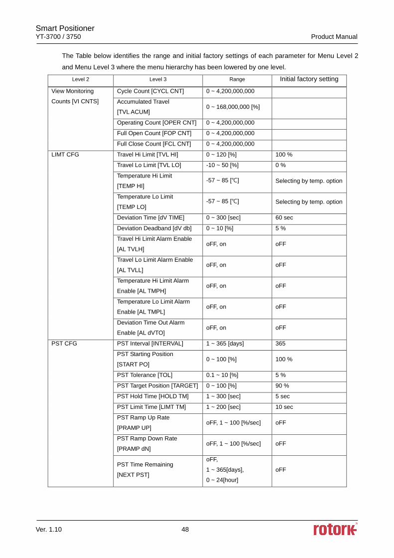
The Table below identifies the range and initial factory settings of each parameter for Menu Level 2
and Menu Level 3 where the menu hierarchy has been lowered by one level.
Level 2 Level 3 Range Initial factory setting
View Monitoring
Counts [VI CNTS]
Cycle Count [CYCL CNT] 0 ~ 4,200,000,000
Accumulated Travel
[TVL ACUM] 0 ~ 168,000,000 [%]
Operating Count [OPER CNT] 0 ~ 4,200,000,000
Full Open Count [FOP CNT] 0 ~ 4,200,000,000
Full Close Count [FCL CNT] 0 ~ 4,200,000,000
LIMT CFG Travel Hi Limit [TVL HI] 0 ~ 120 [%] 100 %
Travel Lo Limit [TVL LO] -10 ~ 50 [%] 0 %
Temperature Hi Limit
[TEMP HI] -57 ~ 85 [] Selecting by temp. option
Temperature Lo Limit
[TEMP LO] -57 ~ 85 [] Selecting by temp. option
Deviation Time [dV TIME] 0 ~ 300 [sec] 60 sec
Deviation Deadband [dV db] 0 ~ 10 [%] 5 %
Travel Hi Limit Alarm Enable
[AL TVLH] oFF, on oFF
Travel Lo Limit Alarm Enable
[AL TVLL] oFF, on oFF
Temperature Hi Limit Alarm
Enable [AL TMPH] oFF, on oFF
Temperature Lo Limit Alarm
Enable [AL TMPL] oFF, on oFF
Deviation Time Out Alarm
Enable [AL dVTO] oFF, on oFF
PST CFG PST Interval [INTERVAL] 1 ~ 365 [days] 365
PST Starting Position
[START PO] 0 ~ 100 [%] 100 %
PST Tolerance [TOL] 0.1 ~ 10 [%] 5 %
PST Target Position [TARGET] 0 ~ 100 [%] 90 %
PST Hold Time [HOLD TM] 1 ~ 300 [sec] 5 sec
PST Limit Time [LIMT TM] 1 ~ 200 [sec] 10 sec
PST Ramp Up Rate
[PRAMP UP] oFF, 1 ~ 100 [%/sec] oFF
PST Ramp Down Rate
[PRAMP dN] oFF, 1 ~ 100 [%/sec] oFF
PST Time Remaining
[NEXT PST]
oFF,
1 ~ 365[days],
0 ~ 24[hour]
oFF
Smart Positioner YT-3700 / 3750 Product Manual
Ver. 1.10 49
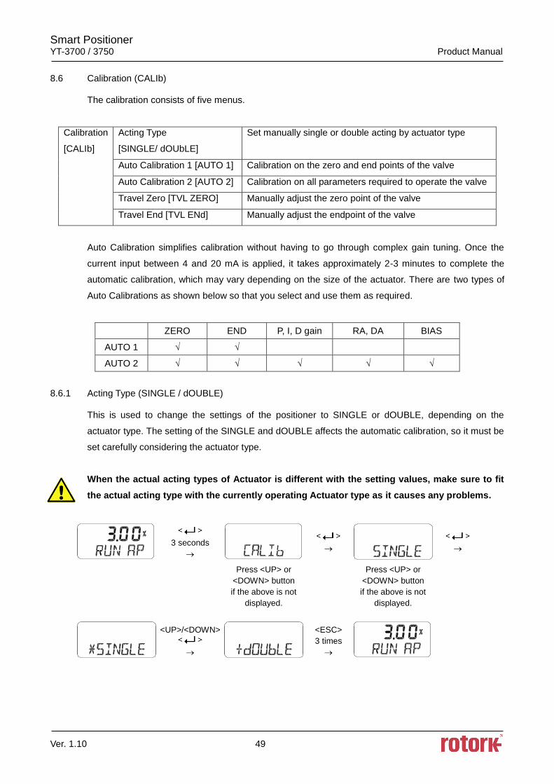
8.6 Calibration (CALIb)
The calibration consists of five menus.
Calibration
[CALIb]
Acting Type
[SINGLE/ dOUbLE]
Set manually single or double acting by actuator type
Auto Calibration 1 [AUTO 1] Calibration on the zero and end points of the valve
Auto Calibration 2 [AUTO 2] Calibration on all parameters required to operate the valve
Travel Zero [TVL ZERO] Manually adjust the zero point of the valve
Travel End [TVL ENd] Manually adjust the endpoint of the valve
Auto Calibration simplifies calibration without having to go through complex gain tuning. Once the
current input between 4 and 20 mA is applied, it takes approximately 2-3 minutes to complete the
automatic calibration, which may vary depending on the size of the actuator. There are two types of
Auto Calibrations as shown below so that you select and use them as required.
ZERO END P, I, D gain RA, DA BIAS
AUTO 1 √ √
AUTO 2 √ √ √ √ √
8.6.1 Acting Type (SINGLE / dOUBLE)
This is used to change the settings of the positioner to SINGLE or dOUBLE, depending on the
actuator type. The setting of the SINGLE and dOUBLE affects the automatic calibration, so it must be
set carefully considering the actuator type.
When the actual acting types of Actuator is different with the setting values, make sure to fit
the actual acting type with the currently operating Actuator type as it causes any problems.
3 seconds
Press <UP> or
<DOWN> button
if the above is not
displayed.
Press <UP> or
<DOWN> button
if the above is not
displayed.
<UP>/<DOWN>
<ESC>
3 times
Smart Positioner YT-3700 / 3750 Product Manual
Ver. 1.10 50
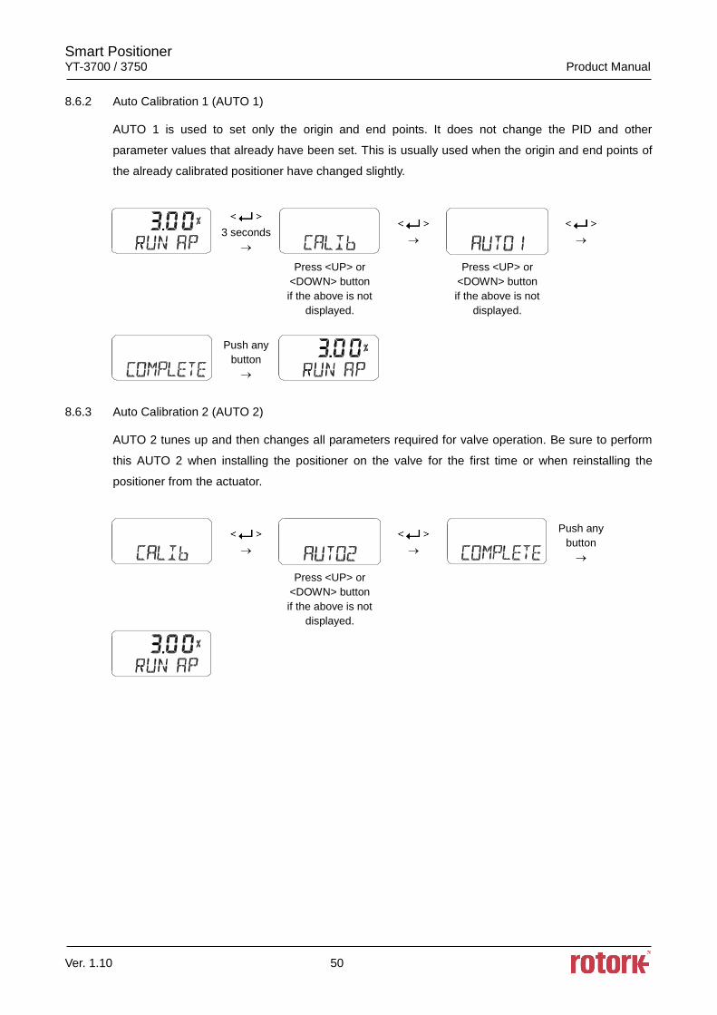
8.6.2 Auto Calibration 1 (AUTO 1)
AUTO 1 is used to set only the origin and end points. It does not change the PID and other
parameter values that already have been set. This is usually used when the origin and end points of
the already calibrated positioner have changed slightly.
3 seconds
Press <UP> or
<DOWN> button
if the above is not
displayed.
Press <UP> or
<DOWN> button
if the above is not
displayed.
Push any
button
8.6.3 Auto Calibration 2 (AUTO 2)
AUTO 2 tunes up and then changes all parameters required for valve operation. Be sure to perform
this AUTO 2 when installing the positioner on the valve for the first time or when reinstalling the
positioner from the actuator.
Push any
button
Press <UP> or
<DOWN> button
if the above is not
displayed.
Smart Positioner YT-3700 / 3750 Product Manual
Ver. 1.10 51
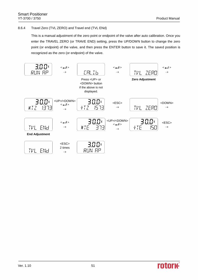
8.6.4 Travel Zero (TVL ZERO) and Travel end (TVL ENd)
This is a manual adjustment of the zero point or endpoint of the valve after auto calibration. Once you
enter the TRAVEL ZERO (or TRAVE END) setting, press the UP/DOWN button to change the zero
point (or endpoint) of the valve, and then press the ENTER button to save it. The saved position is
recognized as the zero (or endpoint) of the valve.
Press <UP> or
<DOWN> button
if the above is not
displayed.
Zero Adjustment
<UP>/<DOWN>
<ESC>
<DOWN>
<UP>/<DOWN>
<ESC>
End Adjustment
<ESC>
2 times
Smart Positioner YT-3700 / 3750 Product Manual
Ver. 1.10 52
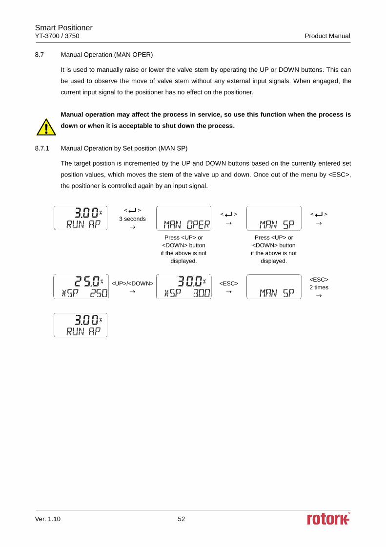
8.7 Manual Operation (MAN OPER)
It is used to manually raise or lower the valve stem by operating the UP or DOWN buttons. This can
be used to observe the move of valve stem without any external input signals. When engaged, the
current input signal to the positioner has no effect on the positioner.
Manual operation may affect the process in service, so use this function when the process is
down or when it is acceptable to shut down the process.
8.7.1 Manual Operation by Set position (MAN SP)
The target position is incremented by the UP and DOWN buttons based on the currently entered set
position values, which moves the stem of the valve up and down. Once out of the menu by <ESC>,
the positioner is controlled again by an input signal.
3 seconds
Press <UP> or
<DOWN> button
if the above is not
displayed.
Press <UP> or
<DOWN> button
if the above is not
displayed.
<UP>/<DOWN>
<ESC>
<ESC>
2 times
Smart Positioner YT-3700 / 3750 Product Manual
Ver. 1.10 53
8.7.2 Manual Operation by MV (MAN MV)
The input to I/P converter is incremented or decremented by the UP and DOWN buttons based on
the currently entered I/P input value, which moves the stem of the valve up and down. Once out of
the menu by <ESC>, the positioner is controlled again by an input signal.
3 seconds
Press <UP> or
<DOWN> button
if the above is not
displayed.
Press <UP> or
<DOWN> button
if the above is not
displayed.
<UP>/<DOWN>
<ESC>
<ESC>
2 times
Smart Positioner YT-3700 / 3750 Product Manual
Ver. 1.10 54
8.8 Control Parameters (CTL PARM)
Followings are the values changeable at the Control Parameters Mode.
1) Dead Band (dEAdbANd)
2) Forward P parameter (KP UP) and reverse P parameter (KP dN)
3) Forward Integral time parameter (TI UP) and reverse Integral time parameter (TI dN)
4) Forward D parameter (Kd UP) and reverse D parameter (Kd dN)
5) Auto Dead band Mode (AUTO db)
6) Performance Mode (PER)
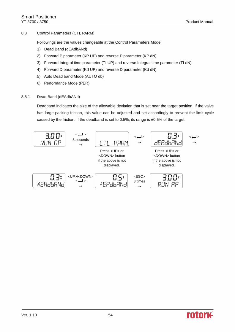
8.8.1 Dead Band (dEAdbANd)
Deadband indicates the size of the allowable deviation that is set near the target position. If the valve
has large packing friction, this value can be adjusted and set accordingly to prevent the limit cycle
caused by the friction. If the deadband is set to 0.5%, its range is ±0.5% of the target.
3 seconds
Press <UP> or
<DOWN> button
if the above is not
displayed.
Press <UP> or
<DOWN> button
if the above is not
displayed.
<UP>/<DOWN>
<ESC>
3 times
Smart Positioner YT-3700 / 3750 Product Manual
Ver. 1.10 55
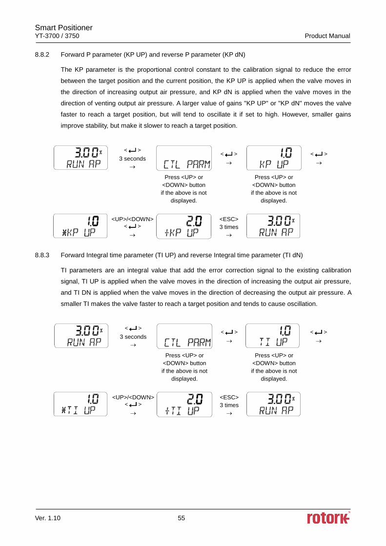
8.8.2 Forward P parameter (KP UP) and reverse P parameter (KP dN)
The KP parameter is the proportional control constant to the calibration signal to reduce the error
between the target position and the current position, the KP UP is applied when the valve moves in
the direction of increasing output air pressure, and KP dN is applied when the valve moves in the
direction of venting output air pressure. A larger value of gains "KP UP" or "KP dN" moves the valve
faster to reach a target position, but will tend to oscillate it if set to high. However, smaller gains
improve stability, but make it slower to reach a target position.
3 seconds
Press <UP> or
<DOWN> button
if the above is not
displayed.
Press <UP> or
<DOWN> button
if the above is not
displayed.
<UP>/<DOWN>
<ESC>
3 times
8.8.3 Forward Integral time parameter (TI UP) and reverse Integral time parameter (TI dN)
TI parameters are an integral value that add the error correction signal to the existing calibration
signal, TI UP is applied when the valve moves in the direction of increasing the output air pressure,
and TI DN is applied when the valve moves in the direction of decreasing the output air pressure. A
smaller TI makes the valve faster to reach a target position and tends to cause oscillation.
3 seconds
Press <UP> or
<DOWN> button
if the above is not
displayed.
Press <UP> or
<DOWN> button
if the above is not
displayed.
<UP>/<DOWN>
<ESC>
3 times
Smart Positioner YT-3700 / 3750 Product Manual
Ver. 1.10 56
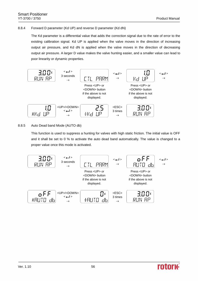
8.8.4 Forward D parameter (Kd UP) and reverse D parameter (Kd dN)
The Kd parameter is a differential value that adds the correction signal due to the rate of error to the
existing calibration signal. Kd UP is applied when the valve moves in the direction of increasing
output air pressure, and Kd dN is applied when the valve moves in the direction of decreasing
output air pressure. A larger D value makes the valve hunting easier, and a smaller value can lead to
poor linearity or dynamic properties.
3 seconds
Press <UP> or
<DOWN> button
if the above is not
displayed.
Press <UP> or
<DOWN> button
if the above is not
displayed.
<UP>/<DOWN>
<ESC>
3 times
8.8.5 Auto Dead band Mode (AUTO db)
This function is used to suppress a hunting for valves with high static friction. The initial value is OFF
and it shall be set to 0 % to activate the auto dead band automatically. The value is changed to a
proper value once this mode is activated.
3 seconds
Press <UP> or
<DOWN> button
if the above is not
displayed.
Press <UP> or
<DOWN> button
if the above is not
displayed.
<UP>/<DOWN>
<ESC>
3 times
Smart Positioner YT-3700 / 3750 Product Manual
Ver. 1.10 57
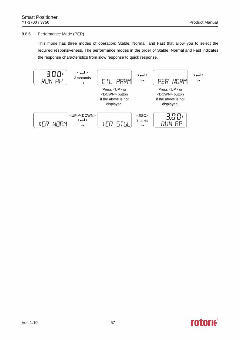
8.8.6 Performance Mode (PER)
This mode has three modes of operation: Stable, Normal, and Fast that allow you to select the
required responsiveness. The performance modes in the order of Stable, Normal and Fast indicates
the response characteristics from slow response to quick response.
3 seconds
Press <UP> or
<DOWN> button
if the above is not
displayed.
Press <UP> or
<DOWN> button
if the above is not
displayed.
<UP>/<DOWN>
<ESC>
3 times
Smart Positioner YT-3700 / 3750 Product Manual
Ver. 1.10 58
8.9 Input Configuration (IN CFG)
Followings are the values changeable at the Input Configuration Mode.
1) Signal Direction (SIG NORM / REVS)
2) Split Range Mode (SPLIT)
3) Custom Split Range Zero (CST ZERO)
4) Custom Split Range End (CST ENd)
5) Characterization Curves (CHAR)
6) User Set Characterization 5 Points (U5)
7) User Set Characterization 21 Points (U21)
8) Tight Shut Open (TSHUT OP)
9) Tight Shut Close (TSHUT CL)
10) Target Position Ramp Up Rate (RAMP UP) and Target Position Ramp Down Rate (RAMP dN)
11) Digital Input Function (dIF)
12) Digital Input Logic (dI LOGIC)
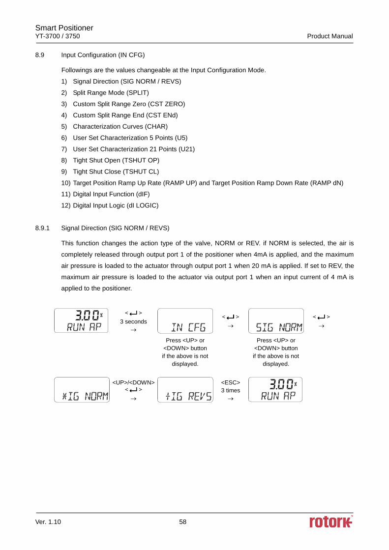
8.9.1 Signal Direction (SIG NORM / REVS)
This function changes the action type of the valve, NORM or REV. if NORM is selected, the air is
completely released through output port 1 of the positioner when 4mA is applied, and the maximum
air pressure is loaded to the actuator through output port 1 when 20 mA is applied. If set to REV, the
maximum air pressure is loaded to the actuator via output port 1 when an input current of 4 mA is
applied to the positioner.
3 seconds
Press <UP> or
<DOWN> button
if the above is not
displayed.
Press <UP> or
<DOWN> button
if the above is not
displayed.
<UP>/<DOWN>
<ESC>
3 times
Smart Positioner YT-3700 / 3750 Product Manual
Ver. 1.10 59
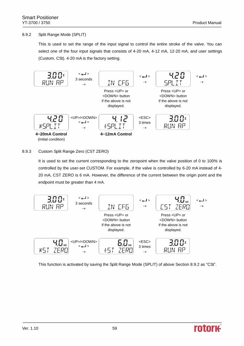
8.9.2 Split Range Mode (SPLIT)
This is used to set the range of the input signal to control the entire stroke of the valve. You can
select one of the four input signals that consists of 4-20 mA, 4-12 mA, 12-20 mA, and user settings
(Custom, CSt). 4-20 mA is the factory setting.
3 seconds
Press <UP> or
<DOWN> button
if the above is not
displayed.
Press <UP> or
<DOWN> button
if the above is not
displayed.
<UP>/<DOWN>
<ESC>
3 times
4~20mA Control
(Initial condition)
4~12mA Control
8.9.3 Custom Split Range Zero (CST ZERO)
It is used to set the current corresponding to the zeropoint when the valve position of 0 to 100% is
controlled by the user-set CUSTOM. For example, if the valve is controlled by 6-20 mA instead of 4-
20 mA, CST ZERO is 6 mA. However, the difference of the current between the origin point and the
endpoint must be greater than 4 mA.
3 seconds
Press <UP> or
<DOWN> button
if the above is not
displayed.
Press <UP> or
<DOWN> button
if the above is not
displayed.
<UP>/<DOWN>
<ESC>
3 times
This function is activated by saving the Split Range Mode (SPLIT) of above Section 8.9.2 as “CSt”.
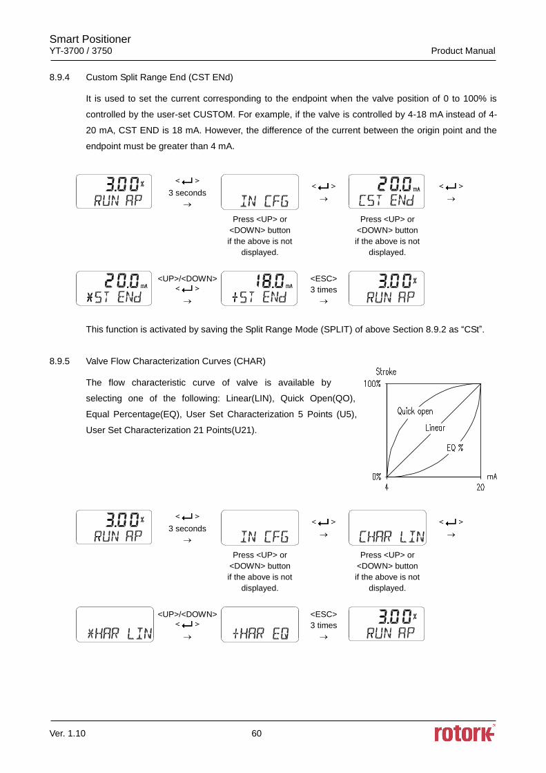
Smart Positioner YT-3700 / 3750 Product Manual
Ver. 1.10 60
8.9.4 Custom Split Range End (CST ENd)
It is used to set the current corresponding to the endpoint when the valve position of 0 to 100% is
controlled by the user-set CUSTOM. For example, if the valve is controlled by 4-18 mA instead of 4-
20 mA, CST END is 18 mA. However, the difference of the current between the origin point and the
endpoint must be greater than 4 mA.
3 seconds
Press <UP> or
<DOWN> button
if the above is not
displayed.
Press <UP> or
<DOWN> button
if the above is not
displayed.
<UP>/<DOWN>
<ESC>
3 times
This function is activated by saving the Split Range Mode (SPLIT) of above Section 8.9.2 as “CSt”.
8.9.5 Valve Flow Characterization Curves (CHAR)
The flow characteristic curve of valve is available by
selecting one of the following: Linear(LIN), Quick Open(QO),
Equal Percentage(EQ), User Set Characterization 5 Points (U5),
User Set Characterization 21 Points(U21).
3 seconds
Press <UP> or
<DOWN> button
if the above is not
displayed.
Press <UP> or
<DOWN> button
if the above is not
displayed.
<UP>/<DOWN>
<ESC>
3 times
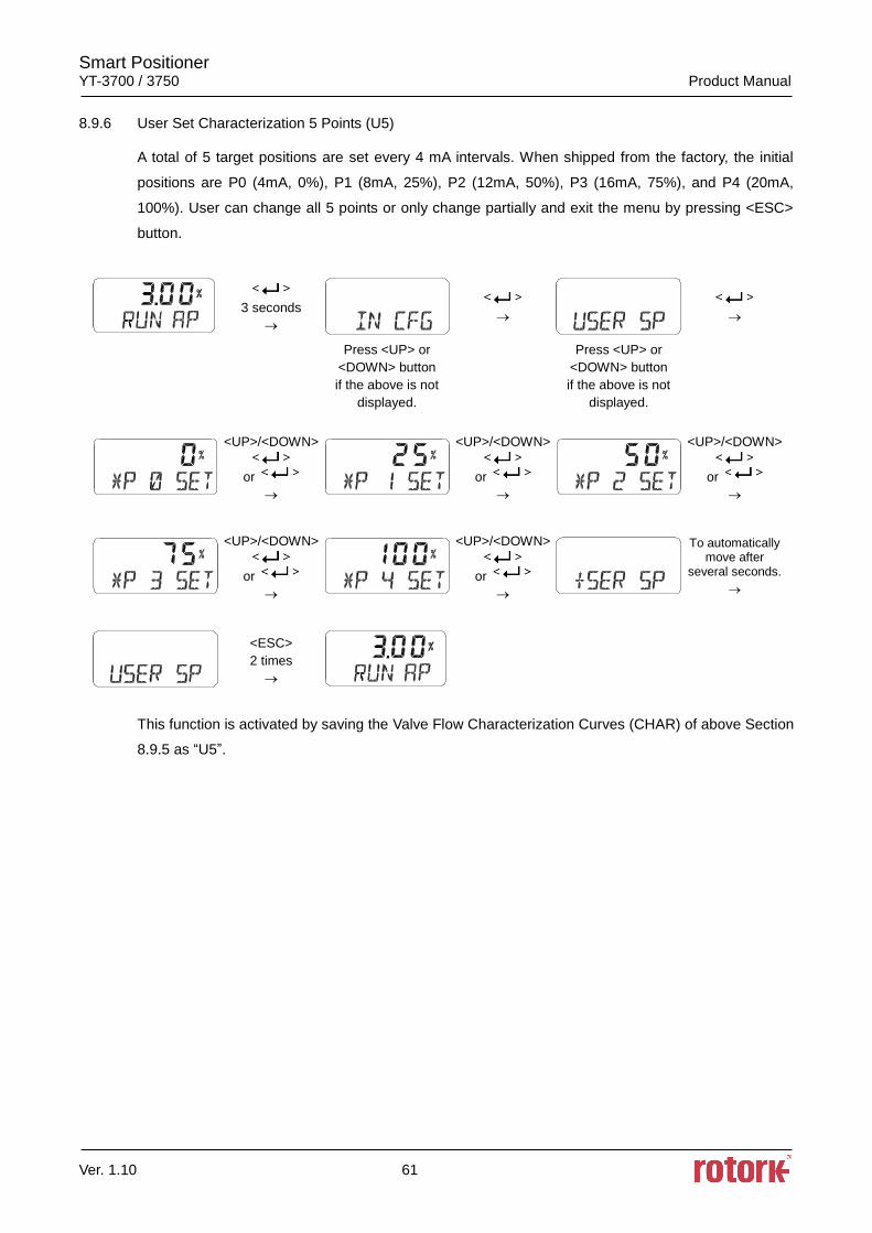
Smart Positioner YT-3700 / 3750 Product Manual
Ver. 1.10 61
8.9.6 User Set Characterization 5 Points (U5)
A total of 5 target positions are set every 4 mA intervals. When shipped from the factory, the initial
positions are P0 (4mA, 0%), P1 (8mA, 25%), P2 (12mA, 50%), P3 (16mA, 75%), and P4 (20mA,
100%). User can change all 5 points or only change partially and exit the menu by pressing <ESC>
button.
3 seconds
Press <UP> or
<DOWN> button
if the above is not
displayed.
Press <UP> or
<DOWN> button
if the above is not
displayed.
<UP>/<DOWN>
or
<UP>/<DOWN>
or
<UP>/<DOWN>
or
<UP>/<DOWN>
or
<UP>/<DOWN>
or
To automatically move after
several seconds.
<ESC>
2 times
This function is activated by saving the Valve Flow Characterization Curves (CHAR) of above Section
8.9.5 as “U5”.
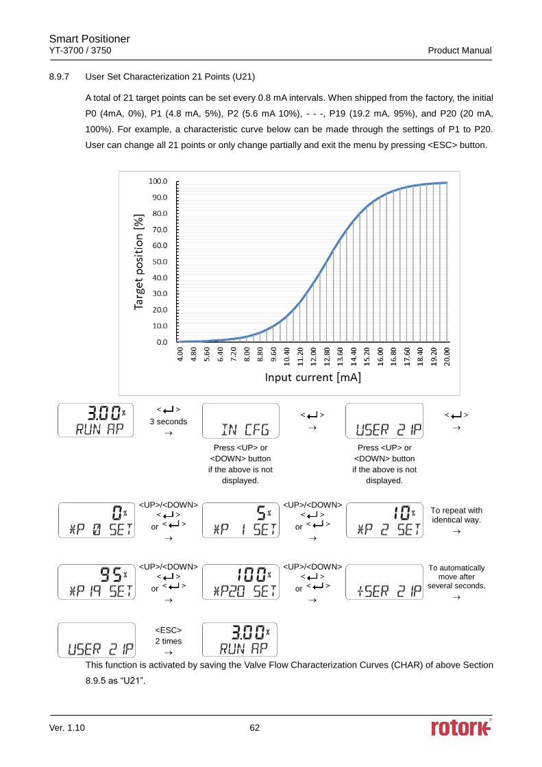
Smart Positioner YT-3700 / 3750 Product Manual
Ver. 1.10 62
8.9.7 User Set Characterization 21 Points (U21)
A total of 21 target points can be set every 0.8 mA intervals. When shipped from the factory, the initial
P0 (4mA, 0%), P1 (4.8 mA, 5%), P2 (5.6 mA 10%), - - -, P19 (19.2 mA, 95%), and P20 (20 mA,
100%). For example, a characteristic curve below can be made through the settings of P1 to P20.
User can change all 21 points or only change partially and exit the menu by pressing <ESC> button.
3 seconds
Press <UP> or
<DOWN> button
if the above is not
displayed.
Press <UP> or
<DOWN> button
if the above is not
displayed.
<UP>/<DOWN>
or
<UP>/<DOWN>
or
To repeat with identical way.
<UP>/<DOWN>
or
<UP>/<DOWN>
or
To automatically move after
several seconds.
<ESC>
2 times
This function is activated by saving the Valve Flow Characterization Curves (CHAR) of above Section
8.9.5 as “U21”.
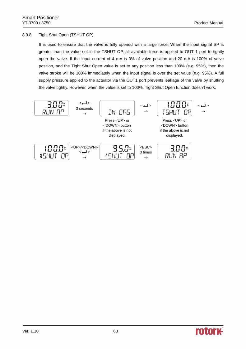
Smart Positioner YT-3700 / 3750 Product Manual
Ver. 1.10 63
8.9.8 Tight Shut Open (TSHUT OP)
It is used to ensure that the valve is fully opened with a large force. When the input signal SP is
greater than the value set in the TSHUT OP, all available force is applied to OUT 1 port to tightly
open the valve. If the input current of 4 mA is 0% of valve position and 20 mA is 100% of valve
position, and the Tight Shut Open value is set to any position less than 100% (e.g. 95%), then the
valve stroke will be 100% immediately when the input signal is over the set value (e.g. 95%). A full
supply pressure applied to the actuator via the OUT1 port prevents leakage of the valve by shutting
the valve tightly. However, when the value is set to 100%, Tight Shut Open function doesn’t work.
3 seconds
Press <UP> or
<DOWN> button
if the above is not
displayed.
Press <UP> or
<DOWN> button
if the above is not
displayed.
<UP>/<DOWN>
<ESC>
3 times
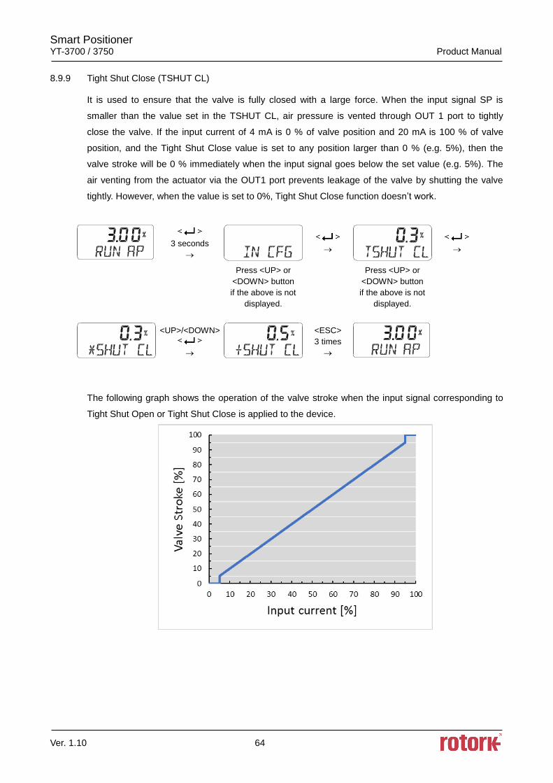
Smart Positioner YT-3700 / 3750 Product Manual
Ver. 1.10 64
8.9.9 Tight Shut Close (TSHUT CL)
It is used to ensure that the valve is fully closed with a large force. When the input signal SP is
smaller than the value set in the TSHUT CL, air pressure is vented through OUT 1 port to tightly
close the valve. If the input current of 4 mA is 0 % of valve position and 20 mA is 100 % of valve
position, and the Tight Shut Close value is set to any position larger than 0 % (e.g. 5%), then the
valve stroke will be 0 % immediately when the input signal goes below the set value (e.g. 5%). The
air venting from the actuator via the OUT1 port prevents leakage of the valve by shutting the valve
tightly. However, when the value is set to 0%, Tight Shut Close function doesn’t work.
3 seconds
Press <UP> or
<DOWN> button
if the above is not
displayed.
Press <UP> or
<DOWN> button
if the above is not
displayed.
<UP>/<DOWN>
<ESC>
3 times
The following graph shows the operation of the valve stroke when the input signal corresponding to
Tight Shut Open or Tight Shut Close is applied to the device.
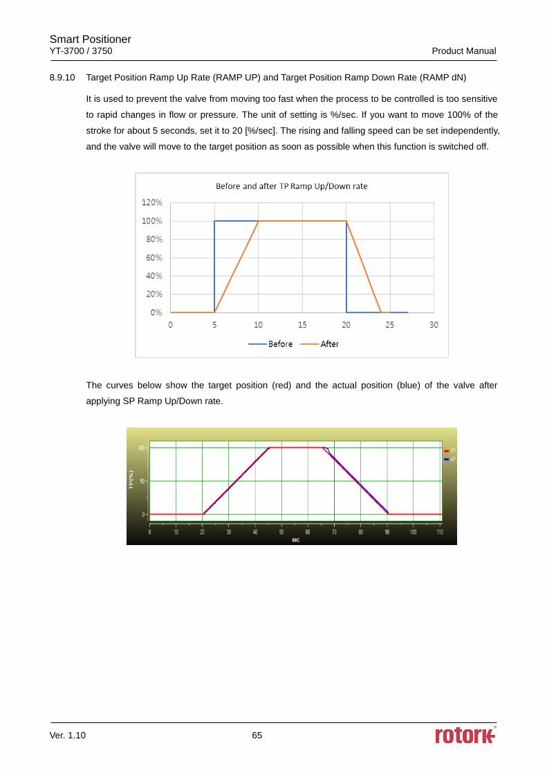
Smart Positioner YT-3700 / 3750 Product Manual
Ver. 1.10 65
8.9.10 Target Position Ramp Up Rate (RAMP UP) and Target Position Ramp Down Rate (RAMP dN)
It is used to prevent the valve from moving too fast when the process to be controlled is too sensitive
to rapid changes in flow or pressure. The unit of setting is %/sec. If you want to move 100% of the
stroke for about 5 seconds, set it to 20 [%/sec]. The rising and falling speed can be set independently,
and the valve will move to the target position as soon as possible when this function is switched off.
The curves below show the target position (red) and the actual position (blue) of the valve after
applying SP Ramp Up/Down rate.
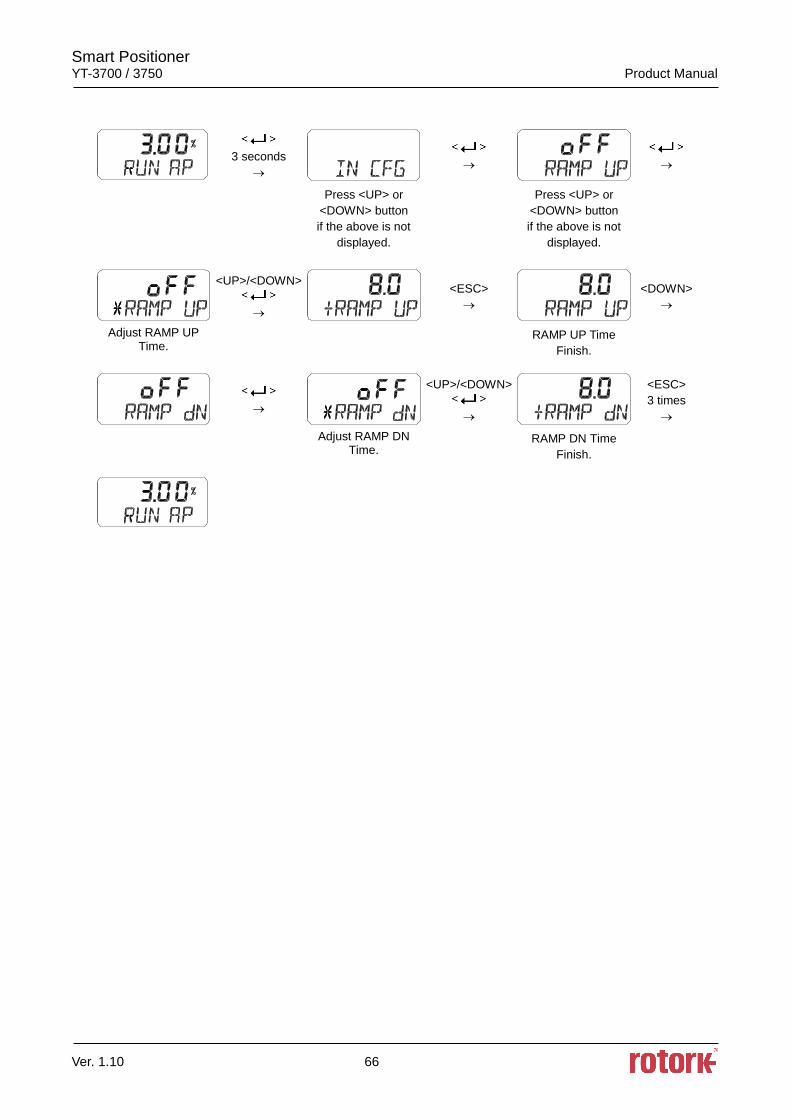
Smart Positioner YT-3700 / 3750 Product Manual
Ver. 1.10 66
3 seconds
Press <UP> or
<DOWN> button
if the above is not
displayed.
Press <UP> or
<DOWN> button
if the above is not
displayed.
<UP>/<DOWN>
<ESC>
<DOWN>
Adjust RAMP UP Time.
RAMP UP Time
Finish.
<UP>/<DOWN>
<ESC>
3 times
Adjust RAMP DN Time.
RAMP DN Time
Finish.
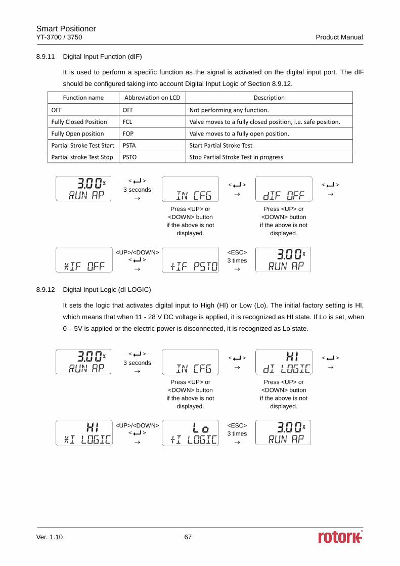
Smart Positioner YT-3700 / 3750 Product Manual
Ver. 1.10 67
8.9.11 Digital Input Function (dIF)
It is used to perform a specific function as the signal is activated on the digital input port. The dIF
should be configured taking into account Digital Input Logic of Section 8.9.12.
Function name Abbreviation on LCD Description
OFF OFF Not performing any function.
Fully Closed Position FCL Valve moves to a fully closed position, i.e. safe position.
Fully Open position FOP Valve moves to a fully open position.
Partial Stroke Test Start PSTA Start Partial Stroke Test
Partial stroke Test Stop PSTO Stop Partial Stroke Test in progress
3 seconds
Press <UP> or
<DOWN> button
if the above is not
displayed.
Press <UP> or
<DOWN> button
if the above is not
displayed.
<UP>/<DOWN>
<ESC>
3 times
8.9.12 Digital Input Logic (dI LOGIC)
It sets the logic that activates digital input to High (HI) or Low (Lo). The initial factory setting is HI,
which means that when 11 - 28 V DC voltage is applied, it is recognized as HI state. If Lo is set, when
0 – 5V is applied or the electric power is disconnected, it is recognized as Lo state.
3 seconds
Press <UP> or
<DOWN> button
if the above is not
displayed.
Press <UP> or
<DOWN> button
if the above is not
displayed.
<UP>/<DOWN>
<ESC>
3 times
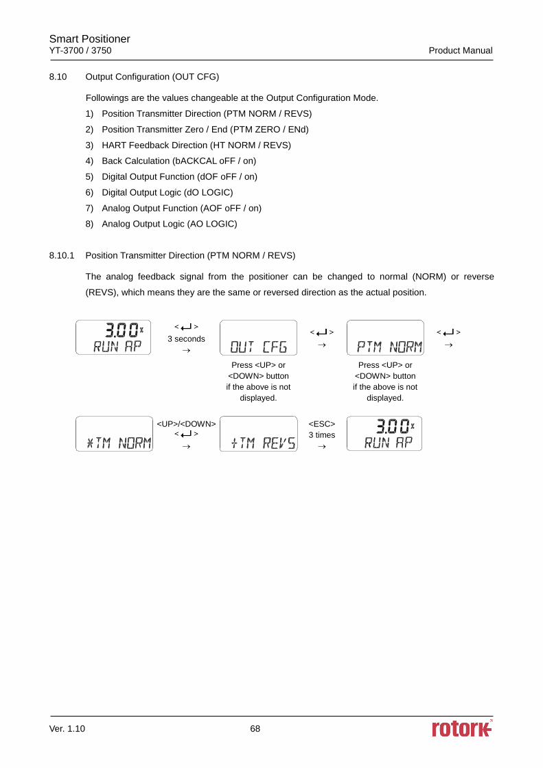
Smart Positioner YT-3700 / 3750 Product Manual
Ver. 1.10 68
8.10 Output Configuration (OUT CFG)
Followings are the values changeable at the Output Configuration Mode.
1) Position Transmitter Direction (PTM NORM / REVS)
2) Position Transmitter Zero / End (PTM ZERO / ENd)
3) HART Feedback Direction (HT NORM / REVS)
4) Back Calculation (bACKCAL oFF / on)
5) Digital Output Function (dOF oFF / on)
6) Digital Output Logic (dO LOGIC)
7) Analog Output Function (AOF oFF / on)
8) Analog Output Logic (AO LOGIC)
8.10.1 Position Transmitter Direction (PTM NORM / REVS)
The analog feedback signal from the positioner can be changed to normal (NORM) or reverse
(REVS), which means they are the same or reversed direction as the actual position.
3 seconds
Press <UP> or
<DOWN> button
if the above is not
displayed.
Press <UP> or
<DOWN> button
if the above is not
displayed.
<UP>/<DOWN>
<ESC>
3 times
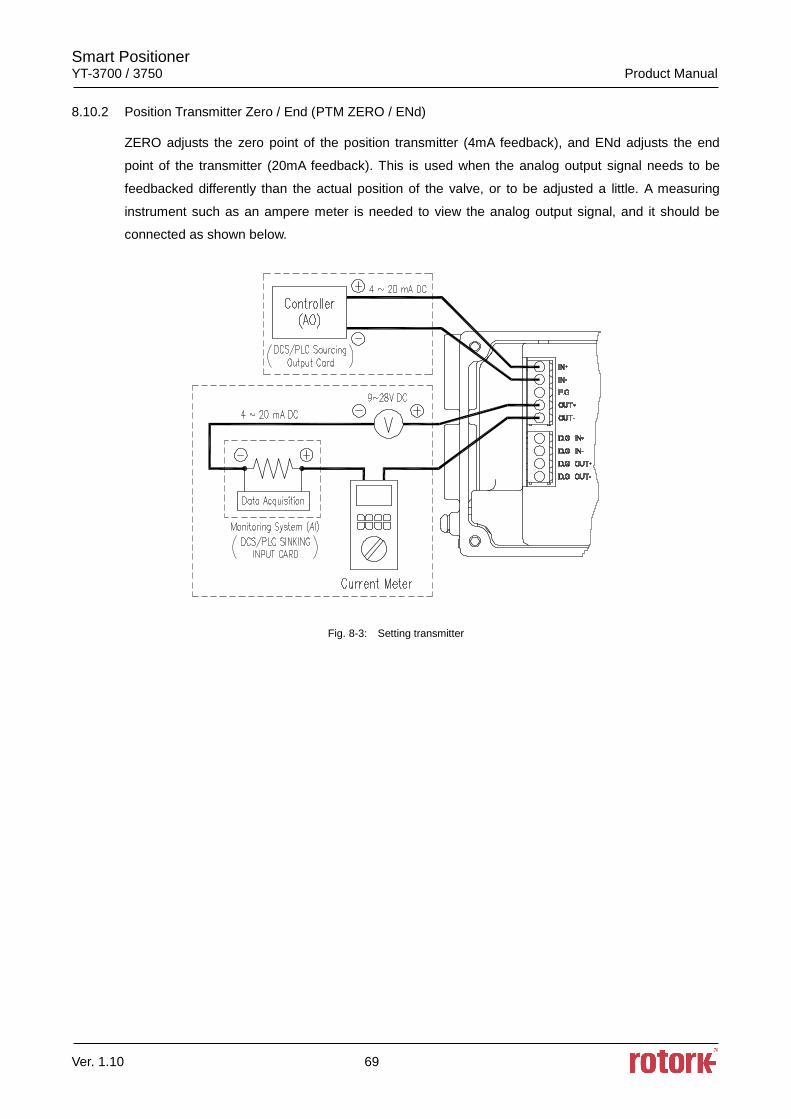
Smart Positioner YT-3700 / 3750 Product Manual
Ver. 1.10 69
8.10.2 Position Transmitter Zero / End (PTM ZERO / ENd)
ZERO adjusts the zero point of the position transmitter (4mA feedback), and ENd adjusts the end
point of the transmitter (20mA feedback). This is used when the analog output signal needs to be
feedbacked differently than the actual position of the valve, or to be adjusted a little. A measuring
instrument such as an ampere meter is needed to view the analog output signal, and it should be
connected as shown below.
Fig. 8-3: Setting transmitter
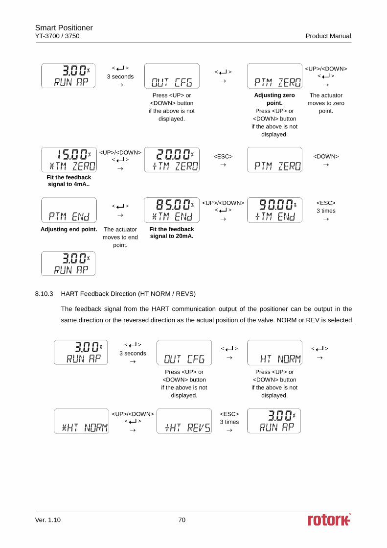
Smart Positioner YT-3700 / 3750 Product Manual
Ver. 1.10 70
3 seconds
<UP>/<DOWN>
Press <UP> or
<DOWN> button
if the above is not
displayed.
Adjusting zero
point.
Press <UP> or
<DOWN> button
if the above is not
displayed.
The actuator
moves to zero
point.
<UP>/<DOWN>
<ESC>
<DOWN>
Fit the feedback signal to 4mA..
<UP>/<DOWN>
<ESC>
3 times
Adjusting end point.
The actuator
moves to end
point.
Fit the feedback signal to 20mA.
8.10.3 HART Feedback Direction (HT NORM / REVS)
The feedback signal from the HART communication output of the positioner can be output in the
same direction or the reversed direction as the actual position of the valve. NORM or REV is selected.
3 seconds
Press <UP> or
<DOWN> button
if the above is not
displayed.
Press <UP> or
<DOWN> button
if the above is not
displayed.
<UP>/<DOWN>
<ESC>
3 times
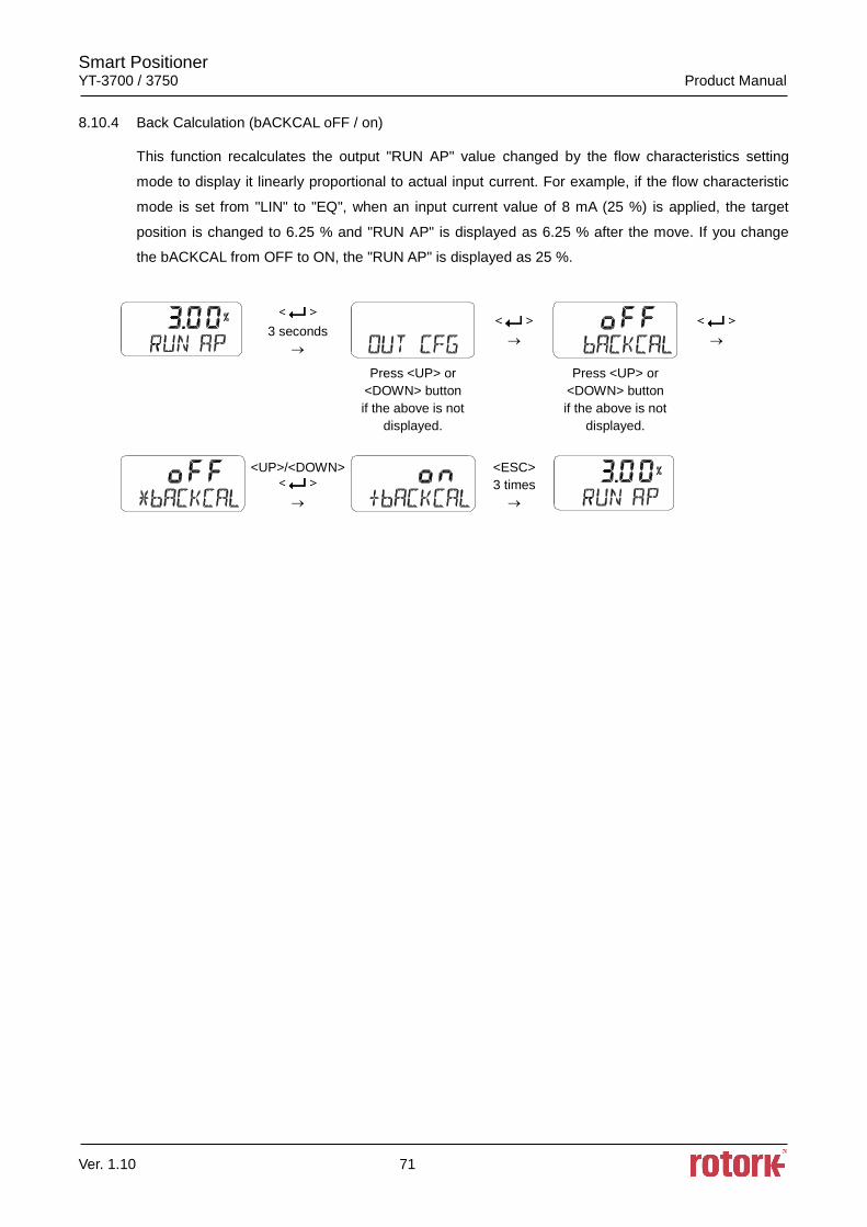
Smart Positioner YT-3700 / 3750 Product Manual
Ver. 1.10 71
8.10.4 Back Calculation (bACKCAL oFF / on)
This function recalculates the output "RUN AP" value changed by the flow characteristics setting
mode to display it linearly proportional to actual input current. For example, if the flow characteristic
mode is set from "LIN" to "EQ", when an input current value of 8 mA (25 %) is applied, the target
position is changed to 6.25 % and "RUN AP" is displayed as 6.25 % after the move. If you change
the bACKCAL from OFF to ON, the "RUN AP" is displayed as 25 %.
3 seconds
Press <UP> or
<DOWN> button
if the above is not
displayed.
Press <UP> or
<DOWN> button
if the above is not
displayed.
<UP>/<DOWN>
<ESC>
3 times
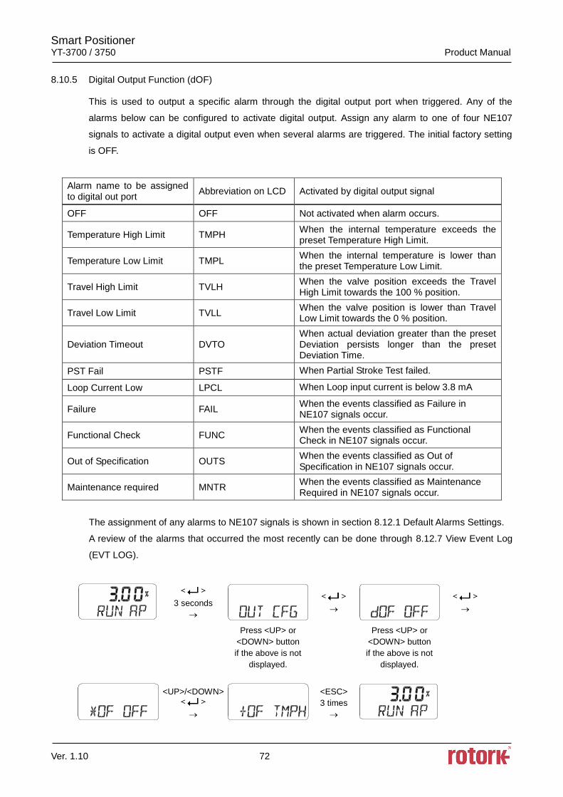
Smart Positioner YT-3700 / 3750 Product Manual
Ver. 1.10 72
8.10.5 Digital Output Function (dOF)
This is used to output a specific alarm through the digital output port when triggered. Any of the
alarms below can be configured to activate digital output. Assign any alarm to one of four NE107
signals to activate a digital output even when several alarms are triggered. The initial factory setting
is OFF.
Alarm name to be assigned to digital out port
Abbreviation on LCD Activated by digital output signal
OFF OFF Not activated when alarm occurs.
Temperature High Limit TMPH When the internal temperature exceeds the preset Temperature High Limit.
Temperature Low Limit TMPL When the internal temperature is lower than the preset Temperature Low Limit.
Travel High Limit TVLH When the valve position exceeds the Travel High Limit towards the 100 % position.
Travel Low Limit TVLL When the valve position is lower than Travel Low Limit towards the 0 % position.
Deviation Timeout DVTO When actual deviation greater than the preset Deviation persists longer than the preset Deviation Time.
PST Fail PSTF When Partial Stroke Test failed.
Loop Current Low LPCL When Loop input current is below 3.8 mA
Failure FAIL When the events classified as Failure in NE107 signals occur.
Functional Check FUNC When the events classified as Functional Check in NE107 signals occur.
Out of Specification OUTS When the events classified as Out of Specification in NE107 signals occur.
Maintenance required MNTR When the events classified as Maintenance Required in NE107 signals occur.
The assignment of any alarms to NE107 signals is shown in section 8.12.1 Default Alarms Settings.
A review of the alarms that occurred the most recently can be done through 8.12.7 View Event Log
(EVT LOG).
3 seconds
Press <UP> or
<DOWN> button
if the above is not
displayed.
Press <UP> or
<DOWN> button
if the above is not
displayed.
<UP>/<DOWN>
<ESC>
3 times
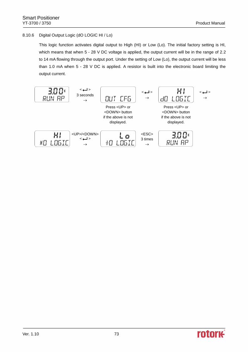
Smart Positioner YT-3700 / 3750 Product Manual
Ver. 1.10 73
8.10.6 Digital Output Logic (dO LOGIC HI / Lo)
This logic function activates digital output to High (HI) or Low (Lo). The initial factory setting is HI,
which means that when 5 - 28 V DC voltage is applied, the output current will be in the range of 2.2
to 14 mA flowing through the output port. Under the setting of Low (Lo), the output current will be less
than 1.0 mA when 5 - 28 V DC is applied. A resistor is built into the electronic board limiting the
output current.
3 seconds
Press <UP> or
<DOWN> button
if the above is not
displayed.
Press <UP> or
<DOWN> button
if the above is not
displayed.
<UP>/<DOWN>
<ESC>
3 times
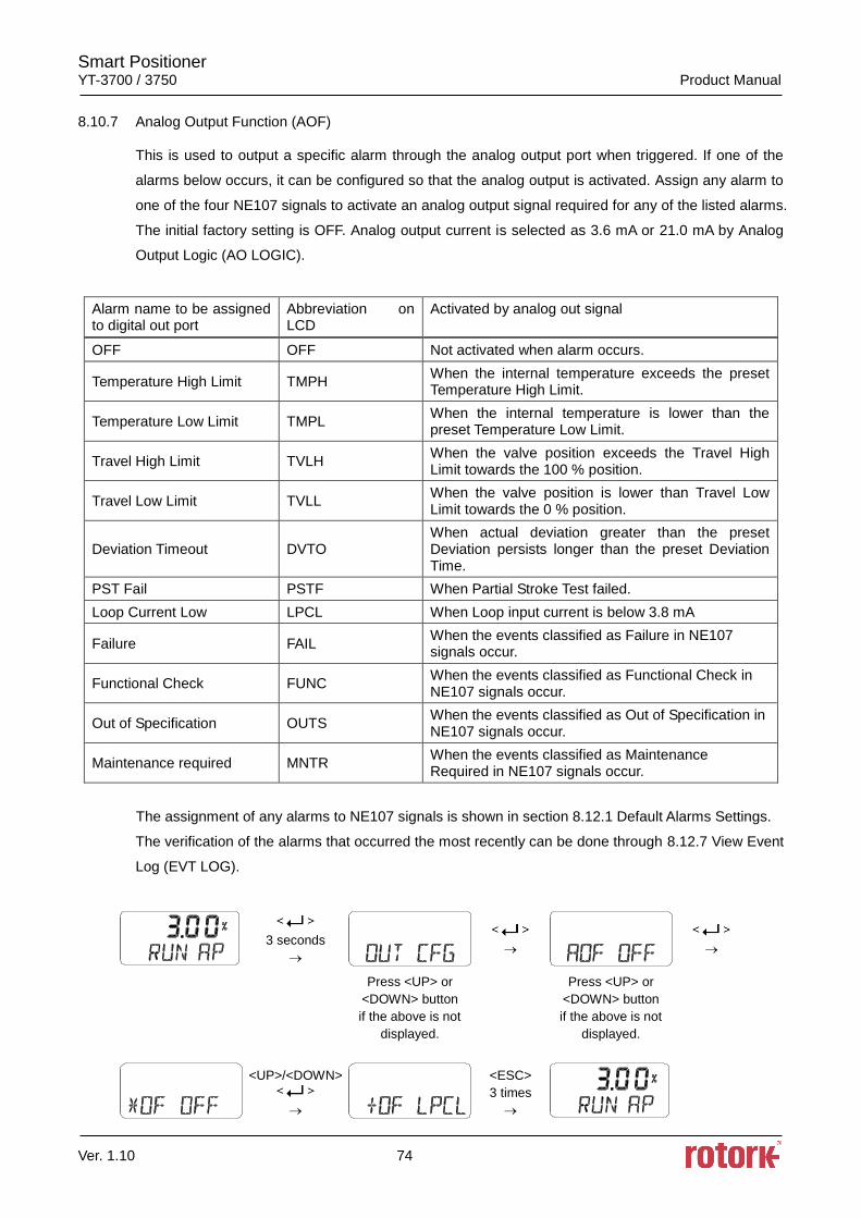
Smart Positioner YT-3700 / 3750 Product Manual
Ver. 1.10 74
8.10.7 Analog Output Function (AOF)
This is used to output a specific alarm through the analog output port when triggered. If one of the
alarms below occurs, it can be configured so that the analog output is activated. Assign any alarm to
one of the four NE107 signals to activate an analog output signal required for any of the listed alarms.
The initial factory setting is OFF. Analog output current is selected as 3.6 mA or 21.0 mA by Analog
Output Logic (AO LOGIC).
Alarm name to be assigned to digital out port
Abbreviation on LCD
Activated by analog out signal
OFF OFF Not activated when alarm occurs.
Temperature High Limit TMPH When the internal temperature exceeds the preset Temperature High Limit.
Temperature Low Limit TMPL When the internal temperature is lower than the preset Temperature Low Limit.
Travel High Limit TVLH When the valve position exceeds the Travel High Limit towards the 100 % position.
Travel Low Limit TVLL When the valve position is lower than Travel Low Limit towards the 0 % position.
Deviation Timeout DVTO When actual deviation greater than the preset Deviation persists longer than the preset Deviation Time.
PST Fail PSTF When Partial Stroke Test failed.
Loop Current Low LPCL When Loop input current is below 3.8 mA
Failure FAIL When the events classified as Failure in NE107 signals occur.
Functional Check FUNC When the events classified as Functional Check in NE107 signals occur.
Out of Specification OUTS When the events classified as Out of Specification in NE107 signals occur.
Maintenance required MNTR When the events classified as Maintenance Required in NE107 signals occur.
The assignment of any alarms to NE107 signals is shown in section 8.12.1 Default Alarms Settings.
The verification of the alarms that occurred the most recently can be done through 8.12.7 View Event
Log (EVT LOG).
3 seconds
Press <UP> or
<DOWN> button
if the above is not
displayed.
Press <UP> or
<DOWN> button
if the above is not
displayed.
<UP>/<DOWN>
<ESC>
3 times

Smart Positioner YT-3700 / 3750 Product Manual
Ver. 1.10 75
8.10.8 Analog Output Logic (AO LOGIC Lo / HI)
This logic function activates the analog output to High (HI) or Low (Lo). A current of less than 3.6 mA
is sourced from the analog output port when the initial factory setting is low (Lo) with an external
voltage source applied to the analog output. When the analog output logic is set to HI, more than
21.0 mA is sourced.
3 seconds
Press <UP> or
<DOWN> button
if the above is not
displayed.
Press <UP> or
<DOWN> button
if the above is not
displayed.
<UP>/<DOWN>
<ESC>
3 times
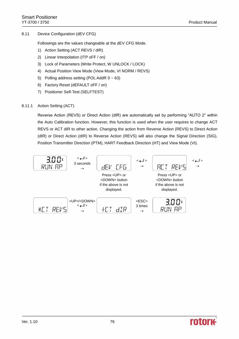
Smart Positioner YT-3700 / 3750 Product Manual
Ver. 1.10 76
8.11 Device Configuration (dEV CFG)
Followings are the values changeable at the dEV CFG Mode.
1) Action Setting (ACT REVS / dIR)
2) Linear Interpolation (ITP oFF / on)
3) Lock of Parameters (Write Protect, W UNLOCK / LOCK)
4) Actual Position View Mode (View Mode, VI NORM / REVS)
5) Polling address setting (POL AddR 0 ~ 63)
6) Factory Reset (dEFAULT oFF / on)
7) Positioner Self-Test (SELFTEST)
8.11.1 Action Setting (ACT)
Reverse Action (REVS) or Direct Action (dIR) are automatically set by performing “AUTO 2” within
the Auto Calibration function. However, this function is used when the user requires to change ACT
REVS or ACT dIR to other action. Changing the action from Reverse Action (REVS) to Direct Action
(dIR) or Direct Action (dIR) to Reverse Action (REVS) will also change the Signal Direction (SIG),
Position Transmitter Direction (PTM), HART Feedback Direction (HT) and View Mode (VI).
3 seconds
Press <UP> or
<DOWN> button
if the above is not
displayed.
Press <UP> or
<DOWN> button
if the above is not
displayed.
<UP>/<DOWN>
<ESC>
3 times
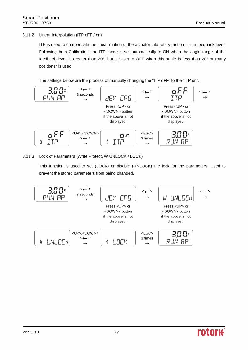
Smart Positioner YT-3700 / 3750 Product Manual
Ver. 1.10 77
8.11.2 Linear Interpolation (ITP oFF / on)
ITP is used to compensate the linear motion of the actuator into rotary motion of the feedback lever.
Following Auto Calibration, the ITP mode is set automatically to ON when the angle range of the
feedback lever is greater than 20°, but it is set to OFF when this angle is less than 20° or rotary
positioner is used.
The settings below are the process of manually changing the “ITP oFF” to the “ITP on”.
3 seconds
Press <UP> or
<DOWN> button
if the above is not
displayed.
Press <UP> or
<DOWN> button
if the above is not
displayed.
<UP>/<DOWN>
<ESC>
3 times
8.11.3 Lock of Parameters (Write Protect, W UNLOCK / LOCK)
This function is used to set (LOCK) or disable (UNLOCK) the lock for the parameters. Used to
prevent the stored parameters from being changed.
3 seconds
Press <UP> or
<DOWN> button
if the above is not
displayed.
Press <UP> or
<DOWN> button
if the above is not
displayed.
<UP>/<DOWN>
<ESC>
3 times
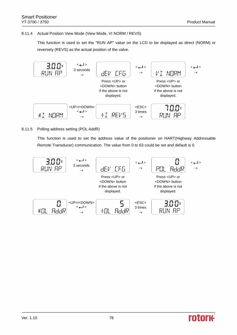
Smart Positioner YT-3700 / 3750 Product Manual
Ver. 1.10 78
8.11.4 Actual Position View Mode (View Mode, VI NORM / REVS)
This function is used to set the "RUN AP" value on the LCD to be displayed as direct (NORM) or
reversely (REVS) as the actual position of the valve.
3 seconds
Press <UP> or
<DOWN> button
if the above is not
displayed.
Press <UP> or
<DOWN> button
if the above is not
displayed.
<UP>/<DOWN>
<ESC>
3 times
8.11.5 Polling address setting (POL AddR)
This function is used to set the address value of the positioner on HART(Highway Addressable
Remote Transducer) communication. The value from 0 to 63 could be set and default is 0.
3 seconds
Press <UP> or
<DOWN> button
if the above is not
displayed.
Press <UP> or
<DOWN> button
if the above is not
displayed.
<UP>/<DOWN>
<ESC>
3 times
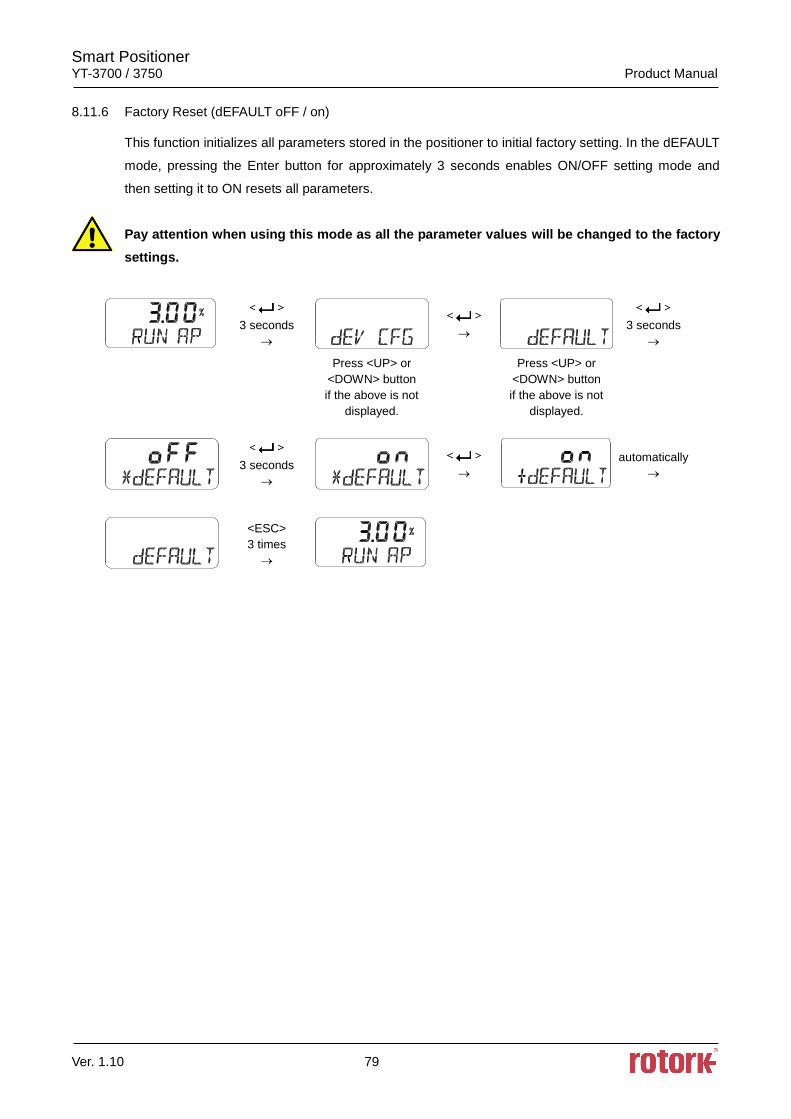
Smart Positioner YT-3700 / 3750 Product Manual
Ver. 1.10 79
8.11.6 Factory Reset (dEFAULT oFF / on)
This function initializes all parameters stored in the positioner to initial factory setting. In the dEFAULT
mode, pressing the Enter button for approximately 3 seconds enables ON/OFF setting mode and
then setting it to ON resets all parameters.
Pay attention when using this mode as all the parameter values will be changed to the factory
settings.
3 seconds
3 seconds
Press <UP> or
<DOWN> button
if the above is not
displayed.
Press <UP> or
<DOWN> button
if the above is not
displayed.
3 seconds
automatically
<ESC>
3 times
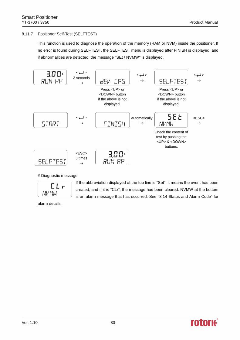
Smart Positioner YT-3700 / 3750 Product Manual
Ver. 1.10 80
8.11.7 Positioner Self-Test (SELFTEST)
This function is used to diagnose the operation of the memory (RAM or NVM) inside the positioner. If
no error is found during SELFTEST, the SELFTEST menu is displayed after FINISH is displayed, and
if abnormalities are detected, the message "SEt / NVMW" is displayed.
3 seconds
Press <UP> or
<DOWN> button
if the above is not
displayed.
Press <UP> or
<DOWN> button
if the above is not
displayed.
automatically
<ESC>
Check the content of
test by pushing the
<UP> & <DOWN>
buttons.
<ESC>
3 times
# Diagnostic message
If the abbreviation displayed at the top line is “Set”, it means the event has been
created, and if it is “CLr”, the message has been cleared. NVMW at the bottom
is an alarm message that has occurred. See "8.14 Status and Alarm Code" for
alarm details.
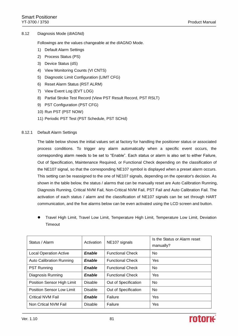
Smart Positioner YT-3700 / 3750 Product Manual
Ver. 1.10 81
8.12 Diagnosis Mode (dIAGNd)
Followings are the values changeable at the dIAGNO Mode.
1) Default Alarm Settings
2) Process Status (PS)
3) Device Status (dS)
4) View Monitoring Counts (VI CNTS)
5) Diagnostic Limit Configuration (LIMT CFG)
6) Reset Alarm Status (RST ALRM)
7) View Event Log (EVT LOG)
8) Partial Stroke Test Record (View PST Result Record, PST RSLT)
9) PST Configuration (PST CFG)
10) Run PST (PST NOW)
11) Periodic PST Test (PST Schedule, PST SCHd)
8.12.1 Default Alarm Settings
The table below shows the initial values set at factory for handling the positioner status or associated
process conditions. To trigger any alarm automatically when a specific event occurs, the
corresponding alarm needs to be set to “Enable”. Each status or alarm is also set to either Failure,
Out of Specification, Maintenance Required, or Functional Check depending on the classification of
the NE107 signal, so that the corresponding NE107 symbol is displayed when a preset alarm occurs.
This setting can be reassigned to the one of NE107 signals, depending on the operator's decision. As
shown in the table below, the status / alarms that can be manually reset are Auto Calibration Running,
Diagnosis Running, Critical NVM Fail, Non-Critical NVM Fail, PST Fail and Auto Calibration Fail. The
activation of each status / alarm and the classification of NE107 signals can be set through HART
communication, and the five alarms below can be even activated using the LCD screen and button.
Travel High Limit, Travel Low Limit, Temperature High Limit, Temperature Low Limit, Deviation
Timeout
Status / Alarm Activation NE107 signals Is the Status or Alarm reset
manually?
Local Operation Active Enable Functional Check No
Auto Calibration Running Enable Functional Check Yes
PST Running Enable Functional Check No
Diagnosis Running Enable Functional Check Yes
Position Sensor High Limit Disable Out of Specification No
Position Sensor Low Limit Disable Out of Specification No
Critical NVM Fail Enable Failure Yes
Non Crtical NVM Fail Disable Failure Yes
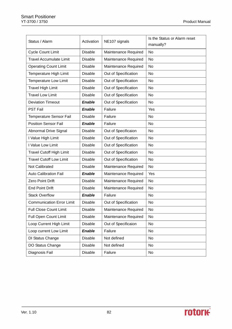
Smart Positioner YT-3700 / 3750 Product Manual
Ver. 1.10 82
Status / Alarm Activation NE107 signals Is the Status or Alarm reset
manually?
Cycle Count Limit Disable Maintenance Required No
Travel Accumulate Limit Disable Maintenance Required No
Operating Count Limit Disable Maintenance Required No
Temperature High Limit Disable Out of Specification No
Temperature Low Limit Disable Out of Specification No
Travel High Limit Disable Out of Specification No
Travel Low Limit Disable Out of Specification No
Deviation Timeout Enable Out of Specification No
PST Fail Enable Failure Yes
Temperature Sensor Fail Disable Failure No
Position Sensor Fail Enable Failure No
Abnormal Drive Signal Disable Out of Specificaion No
I Value High Limit Disable Out of Specification No
I Value Low Limit Disable Out of Specification No
Travel Cutoff High Limit Disable Out of Specification No
Travel Cutoff Low Limit Disable Out of Specification No
Not Calibrated Disable Maintenance Required No
Auto Calibration Fail Enable Maintenance Required Yes
Zero Point Drift Disable Maintenance Required No
End Point Drift Disable Maintenance Required No
Stack Overflow Enable Failure No
Communication Error Limit Disable Out of Specification No
Full Close Count Limit Disable Maintenance Required No
Full Open Count Limit Disable Maintenance Required No
Loop Current High Limit Disable Out of Specificaion No
Loop current Low Limit Enable Failure No
DI Status Change Disable Not defined No
DO Status Change Disable Not defined No
Diagnosis Fail Disable Failure No
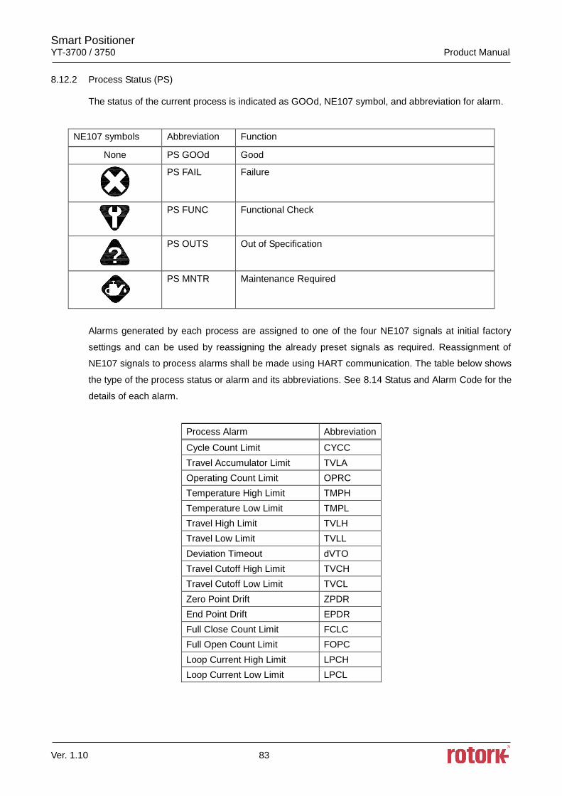
Smart Positioner YT-3700 / 3750 Product Manual
Ver. 1.10 83
8.12.2 Process Status (PS)
The status of the current process is indicated as GOOd, NE107 symbol, and abbreviation for alarm.
NE107 symbols Abbreviation Function
None PS GOOd Good
PS FAIL Failure
PS FUNC Functional Check
PS OUTS Out of Specification
PS MNTR Maintenance Required
Alarms generated by each process are assigned to one of the four NE107 signals at initial factory
settings and can be used by reassigning the already preset signals as required. Reassignment of
NE107 signals to process alarms shall be made using HART communication. The table below shows
the type of the process status or alarm and its abbreviations. See 8.14 Status and Alarm Code for the
details of each alarm.
Process Alarm Abbreviation
Cycle Count Limit CYCC
Travel Accumulator Limit TVLA
Operating Count Limit OPRC
Temperature High Limit TMPH
Temperature Low Limit TMPL
Travel High Limit TVLH
Travel Low Limit TVLL
Deviation Timeout dVTO
Travel Cutoff High Limit TVCH
Travel Cutoff Low Limit TVCL
Zero Point Drift ZPDR
End Point Drift EPDR
Full Close Count Limit FCLC
Full Open Count Limit FOPC
Loop Current High Limit LPCH
Loop Current Low Limit LPCL
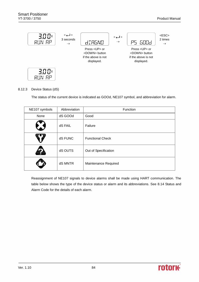
Smart Positioner YT-3700 / 3750 Product Manual
Ver. 1.10 84
3 seconds
<ESC>
2 times
Press <UP> or
<DOWN> button
if the above is not
displayed.
Press <UP> or
<DOWN> button
if the above is not
displayed.
8.12.3 Device Status (dS)
The status of the current device is indicated as GOOd, NE107 symbol, and abbreviation for alarm.
NE107 symbols Abbreviation Function
None dS GOOd Good
dS FAIL Failure
dS FUNC Functional Check
dS OUTS Out of Specification
dS MNTR Maintenance Required
Reassignment of NE107 signals to device alarms shall be made using HART communication. The
table below shows the type of the device status or alarm and its abbreviations. See 8.14 Status and
Alarm Code for the details of each alarm.
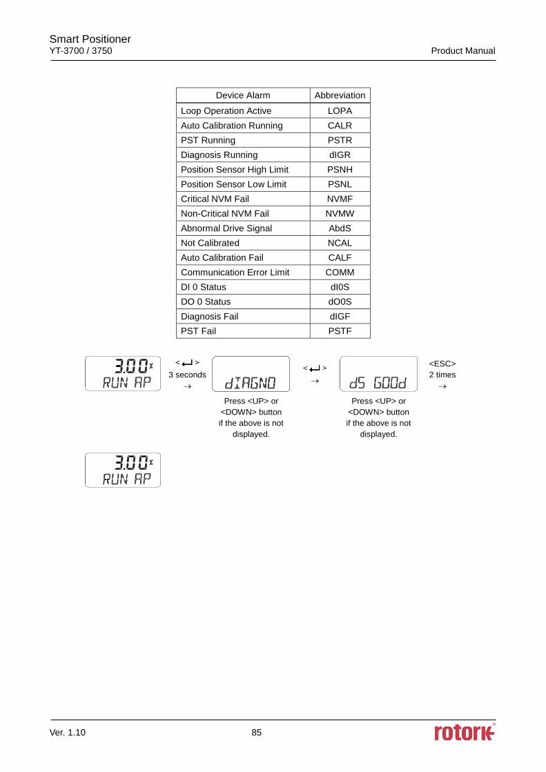
Smart Positioner YT-3700 / 3750 Product Manual
Ver. 1.10 85
Device Alarm Abbreviation
Loop Operation Active LOPA
Auto Calibration Running CALR
PST Running PSTR
Diagnosis Running dIGR
Position Sensor High Limit PSNH
Position Sensor Low Limit PSNL
Critical NVM Fail NVMF
Non-Critical NVM Fail NVMW
Abnormal Drive Signal AbdS
Not Calibrated NCAL
Auto Calibration Fail CALF
Communication Error Limit COMM
DI 0 Status dI0S
DO 0 Status dO0S
Diagnosis Fail dIGF
PST Fail PSTF
3 seconds
<ESC>
2 times
Press <UP> or
<DOWN> button
if the above is not
displayed.
Press <UP> or
<DOWN> button
if the above is not
displayed.
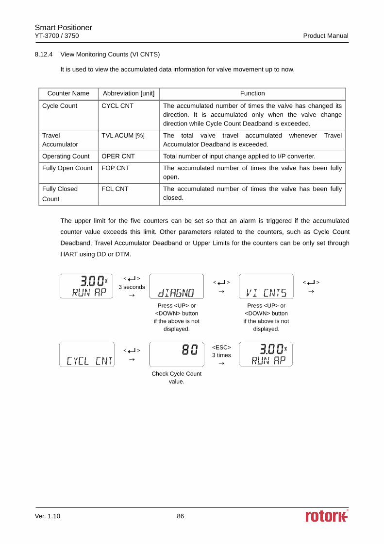
Smart Positioner YT-3700 / 3750 Product Manual
Ver. 1.10 86
8.12.4 View Monitoring Counts (VI CNTS)
It is used to view the accumulated data information for valve movement up to now.
Counter Name Abbreviation [unit] Function
Cycle Count CYCL CNT The accumulated number of times the valve has changed its
direction. It is accumulated only when the valve change
direction while Cycle Count Deadband is exceeded.
Travel
Accumulator
TVL ACUM [%] The total valve travel accumulated whenever Travel
Accumulator Deadband is exceeded.
Operating Count OPER CNT Total number of input change applied to I/P converter.
Fully Open Count FOP CNT The accumulated number of times the valve has been fully
open.
Fully Closed
Count
FCL CNT The accumulated number of times the valve has been fully
closed.
The upper limit for the five counters can be set so that an alarm is triggered if the accumulated
counter value exceeds this limit. Other parameters related to the counters, such as Cycle Count
Deadband, Travel Accumulator Deadband or Upper Limits for the counters can be only set through
HART using DD or DTM.
3 seconds
Press <UP> or
<DOWN> button
if the above is not
displayed.
Press <UP> or
<DOWN> button
if the above is not
displayed.
<ESC>
3 times
Check Cycle Count
value.
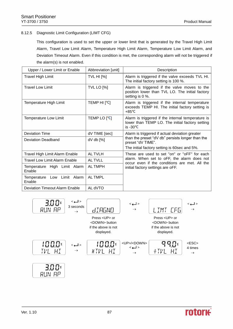
Smart Positioner YT-3700 / 3750 Product Manual
Ver. 1.10 87
8.12.5 Diagnostic Limit Configuration (LIMT CFG)
This configuration is used to set the upper or lower limit that is generated by the Travel High Limit
Alarm, Travel Low Limit Alarm, Temperature High Limit Alarm, Temperature Low Limit Alarm, and
Deviation Timeout Alarm. Even if this condition is met, the corresponding alarm will not be triggered if
the alarm(s) is not enabled.
Upper / Lower Limit or Enable Abbreviation [unit] Description
Travel High Limit TVL HI [%] Alarm is triggered if the valve exceeds TVL HI. The initial factory setting is 100 %.
Travel Low Limit TVL LO [%] Alarm is triggered if the valve moves to the position lower than TVL LO. The initial factory setting is 0 %.
Temperature High Limit TEMP HI [ ] Alarm is triggered if the internal temperature exceeds TEMP HI. The initial factory setting is +85
Temperature Low Limit TEMP LO [ ] Alarm is triggered if the internal temperature is lower than TEMP LO. The initial factory setting is -30
Deviation Time dV TIME [sec] Alarm is triggered if actual deviation greater than the preset “dV db” persists longer than the preset “dV TIME”.
The initial factory setting is 60sec and 5%.
Deviation Deadband dV db [%]
Travel High Limit Alarm Enable AL TVLH These are used to set "on" or "oFF" for each alarm. When set to oFF, the alarm does not occur even if the conditions are met. All the initial factory settings are oFF.
Travel Low Limit Alarm Enable AL TVLL
Temperature High Limit Alarm Enable
AL TMPH
Temperature Low Limit Alarm Enable
AL TMPL
Deviation Timeout Alarm Enable AL dVTO
3 seconds
Press <UP> or
<DOWN> button
if the above is not
displayed.
Press <UP> or
<DOWN> button
if the above is not
displayed.
<UP>/<DOWN>
<ESC>
4 times
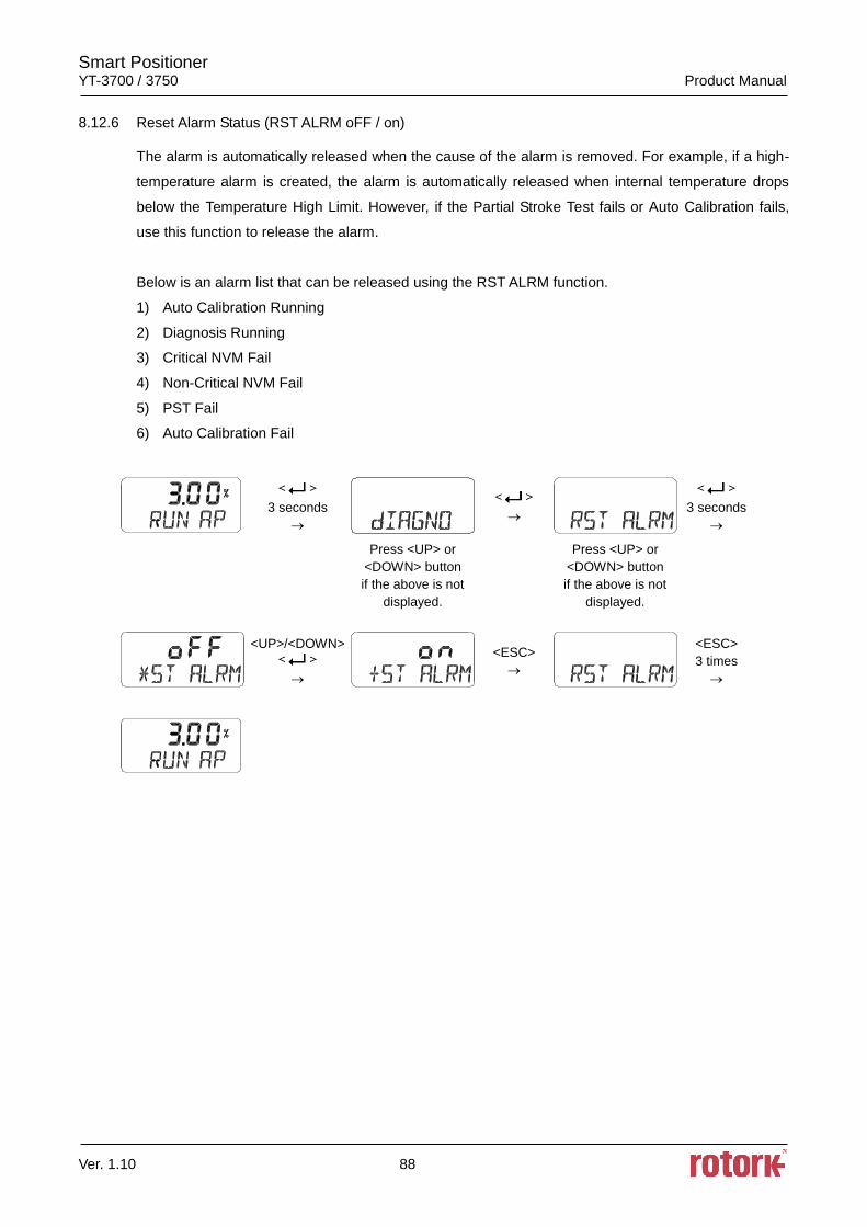
Smart Positioner YT-3700 / 3750 Product Manual
Ver. 1.10 88
8.12.6 Reset Alarm Status (RST ALRM oFF / on)
The alarm is automatically released when the cause of the alarm is removed. For example, if a high-
temperature alarm is created, the alarm is automatically released when internal temperature drops
below the Temperature High Limit. However, if the Partial Stroke Test fails or Auto Calibration fails,
use this function to release the alarm.
Below is an alarm list that can be released using the RST ALRM function.
1) Auto Calibration Running
2) Diagnosis Running
3) Critical NVM Fail
4) Non-Critical NVM Fail
5) PST Fail
6) Auto Calibration Fail
3 seconds
3 seconds
Press <UP> or
<DOWN> button
if the above is not
displayed.
Press <UP> or
<DOWN> button
if the above is not
displayed.
<UP>/<DOWN>
<ESC>
<ESC>
3 times
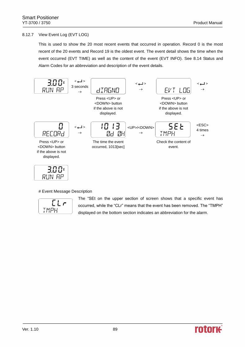
Smart Positioner YT-3700 / 3750 Product Manual
Ver. 1.10 89
8.12.7 View Event Log (EVT LOG)
This is used to show the 20 most recent events that occurred in operation. Record 0 is the most
recent of the 20 events and Record 19 is the oldest event. The event detail shows the time when the
event occurred (EVT TIME) as well as the content of the event (EVT INFO). See 8.14 Status and
Alarm Codes for an abbreviation and description of the event details.
3 seconds
Press <UP> or
<DOWN> button
if the above is not
displayed.
Press <UP> or
<DOWN> button
if the above is not
displayed.
<UP>/<DOWN>
<ESC>
4 times
Press <UP> or
<DOWN> button
if the above is not
displayed.
The time the event
occurred, 1013[sec]
Check the content of
event.
# Event Message Description
The “SEt on the upper section of screen shows that a specific event has
occurred, while the “CLr” means that the event has been removed. The “TMPH”
displayed on the bottom section indicates an abbreviation for the alarm.
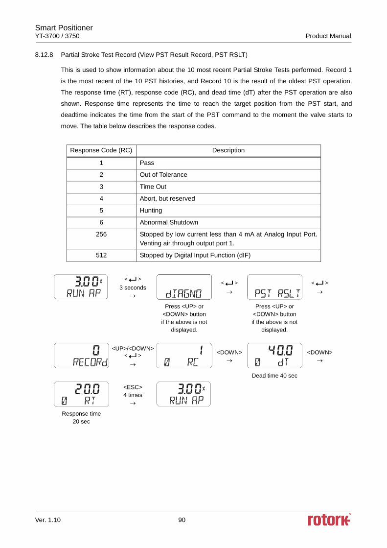
Smart Positioner YT-3700 / 3750 Product Manual
Ver. 1.10 90
8.12.8 Partial Stroke Test Record (View PST Result Record, PST RSLT)
This is used to show information about the 10 most recent Partial Stroke Tests performed. Record 1
is the most recent of the 10 PST histories, and Record 10 is the result of the oldest PST operation.
The response time (RT), response code (RC), and dead time (dT) after the PST operation are also
shown. Response time represents the time to reach the target position from the PST start, and
deadtime indicates the time from the start of the PST command to the moment the valve starts to
move. The table below describes the response codes.
Response Code (RC) Description
1 Pass
2 Out of Tolerance
3 Time Out
4 Abort, but reserved
5 Hunting
6 Abnormal Shutdown
256 Stopped by low current less than 4 mA at Analog Input Port.
Venting air through output port 1.
512 Stopped by Digital Input Function (dIF)
3 seconds
Press <UP> or
<DOWN> button
if the above is not
displayed.
Press <UP> or
<DOWN> button
if the above is not
displayed.
<UP>/<DOWN>
<DOWN>
<DOWN>
Dead time 40 sec
<ESC>
4 times
Response time
20 sec
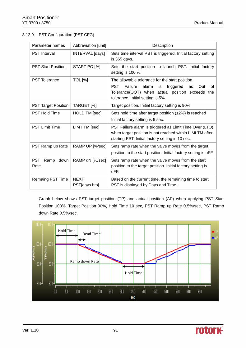
Smart Positioner YT-3700 / 3750 Product Manual
Ver. 1.10 91
8.12.9 PST Configuration (PST CFG)
Parameter names Abbreviation [unit] Description
PST Interval INTERVAL [days] Sets time interval PST is triggered. Initial factory setting
is 365 days.
PST Start Position START PO [%] Sets the start position to launch PST. Initial factory
setting is 100 %.
PST Tolerance TOL [%] The allowable tolerance for the start position.
PST Failure alarm is triggered as Out of
Tolerance(OOT) when actual position exceeds the
tolerance. Initial setting is 5%.
PST Target Position TARGET [%] Target position. Initial factory setting is 90%.
PST Hold Time HOLD TM [sec] Sets hold time after target position (±2%) is reached
Initial factory setting is 5 sec.
PST Limit Time LIMT TM [sec] PST Failure alarm is triggered as Limit Time Over (LTO)
when target position is not reached within LIMI TM after
starting PST. Initial factory setting is 10 sec.
PST Ramp up Rate RAMP UP [%/sec] Sets ramp rate when the valve moves from the target
position to the start position. Initial factory setting is oFF.
PST Ramp down
Rate
RAMP dN [%/sec] Sets ramp rate when the valve moves from the start
position to the target position. Initial factory setting is
oFF.
Remaing PST Time NEXT
PST[days.hrs]
Based on the current time, the remaining time to start
PST is displayed by Days and Time.
Graph below shows PST target position (TP) and actual position (AP) when applying PST Start
Position 100%, Target Position 90%, Hold Time 10 sec, PST Ramp up Rate 0.5%/sec, PST Ramp
down Rate 0.5%/sec.
Ramp down Rate
Hold Time
Hold Time
Dead Time
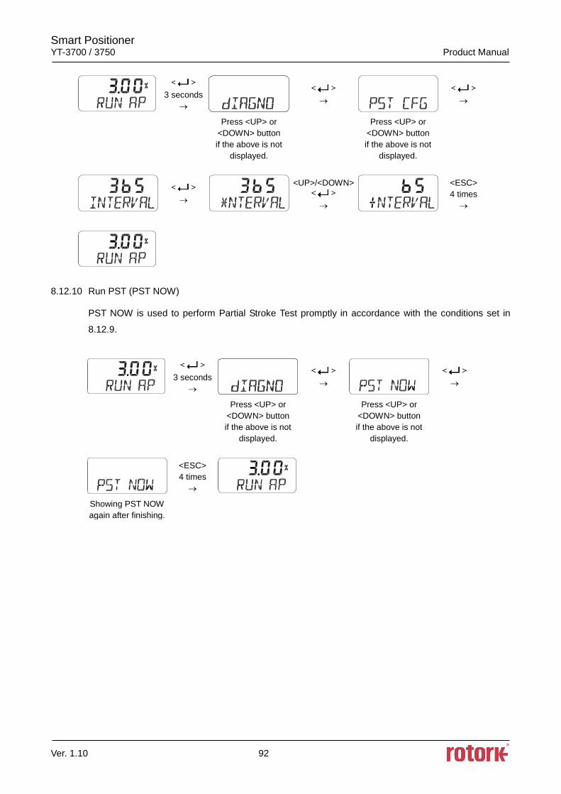
Smart Positioner YT-3700 / 3750 Product Manual
Ver. 1.10 92
3 seconds
Press <UP> or
<DOWN> button
if the above is not
displayed.
Press <UP> or
<DOWN> button
if the above is not
displayed.
<UP>/<DOWN>
<ESC>
4 times
8.12.10 Run PST (PST NOW)
PST NOW is used to perform Partial Stroke Test promptly in accordance with the conditions set in
8.12.9.
3 seconds
Press <UP> or
<DOWN> button
if the above is not
displayed.
Press <UP> or
<DOWN> button
if the above is not
displayed.
<ESC>
4 times
Showing PST NOW
again after finishing.
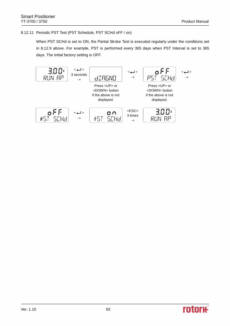
Smart Positioner YT-3700 / 3750 Product Manual
Ver. 1.10 93
8.12.11 Periodic PST Test (PST Schedule, PST SCHd oFF / on)
When PST SCHd is set to ON, the Partial Stroke Test is executed regularly under the conditions set
in 8.12.9 above. For example, PST is performed every 365 days when PST Interval is set to 365
days. The initial factory setting is OFF.
3 seconds
Press <UP> or
<DOWN> button
if the above is not
displayed.
Press <UP> or
<DOWN> button
if the above is not
displayed.
<ESC>
3 times
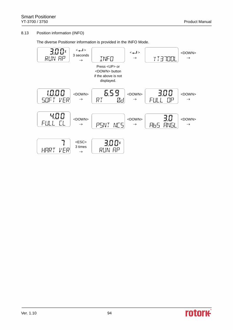
Smart Positioner YT-3700 / 3750 Product Manual
Ver. 1.10 94
8.13 Position information (INFO)
The diverse Positioner information is provided in the INFO Mode.
3 seconds
<DOWN>
Press <UP> or
<DOWN> button
if the above is not
displayed.
<DOWN>
<DOWN>
<DOWN>
<DOWN>
<DOWN>
<DOWN>
<ESC>
3 times
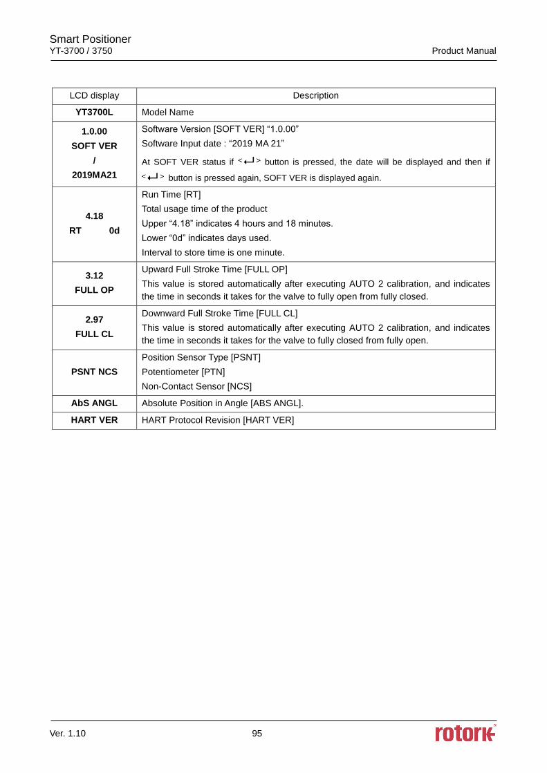
Smart Positioner YT-3700 / 3750 Product Manual
Ver. 1.10 95
LCD display Description
YT3700L Model Name
1.0.00
SOFT VER
/
2019MA21
Software Version [SOFT VER] “1.0.00”
Software Input date : “2019 MA 21”
At SOFT VER status if button is pressed, the date will be displayed and then if
button is pressed again, SOFT VER is displayed again.
4.18
RT 0d
Run Time [RT]
Total usage time of the product
Upper “4.18” indicates 4 hours and 18 minutes.
Lower “0d” indicates days used.
Interval to store time is one minute.
3.12
FULL OP
Upward Full Stroke Time [FULL OP]
This value is stored automatically after executing AUTO 2 calibration, and indicates
the time in seconds it takes for the valve to fully open from fully closed.
2.97
FULL CL
Downward Full Stroke Time [FULL CL]
This value is stored automatically after executing AUTO 2 calibration, and indicates
the time in seconds it takes for the valve to fully closed from fully open.
PSNT NCS
Position Sensor Type [PSNT]
Potentiometer [PTN]
Non-Contact Sensor [NCS]
AbS ANGL Absolute Position in Angle [ABS ANGL].
HART VER HART Protocol Revision [HART VER]
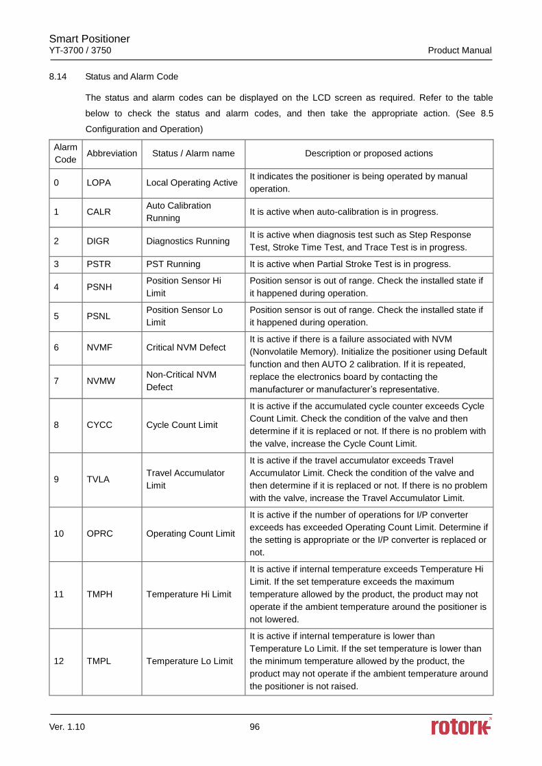
Smart Positioner YT-3700 / 3750 Product Manual
Ver. 1.10 96
8.14 Status and Alarm Code
The status and alarm codes can be displayed on the LCD screen as required. Refer to the table
below to check the status and alarm codes, and then take the appropriate action. (See 8.5
Configuration and Operation)
Alarm
Code Abbreviation Status / Alarm name Description or proposed actions
0 LOPA Local Operating Active It indicates the positioner is being operated by manual
operation.
1 CALR Auto Calibration
Running It is active when auto-calibration is in progress.
2 DIGR Diagnostics Running It is active when diagnosis test such as Step Response
Test, Stroke Time Test, and Trace Test is in progress.
3 PSTR PST Running It is active when Partial Stroke Test is in progress.
4 PSNH Position Sensor Hi
Limit
Position sensor is out of range. Check the installed state if
it happened during operation.
5 PSNL Position Sensor Lo
Limit
Position sensor is out of range. Check the installed state if
it happened during operation.
6 NVMF Critical NVM Defect It is active if there is a failure associated with NVM
(Nonvolatile Memory). Initialize the positioner using Default
function and then AUTO 2 calibration. If it is repeated,
replace the electronics board by contacting the
manufacturer or manufacturer’s representative. 7 NVMW
Non-Critical NVM
Defect
8 CYCC Cycle Count Limit
It is active if the accumulated cycle counter exceeds Cycle
Count Limit. Check the condition of the valve and then
determine if it is replaced or not. If there is no problem with
the valve, increase the Cycle Count Limit.
9 TVLA Travel Accumulator
Limit
It is active if the travel accumulator exceeds Travel
Accumulator Limit. Check the condition of the valve and
then determine if it is replaced or not. If there is no problem
with the valve, increase the Travel Accumulator Limit.
10 OPRC Operating Count Limit
It is active if the number of operations for I/P converter
exceeds has exceeded Operating Count Limit. Determine if
the setting is appropriate or the I/P converter is replaced or
not.
11 TMPH Temperature Hi Limit
It is active if internal temperature exceeds Temperature Hi
Limit. If the set temperature exceeds the maximum
temperature allowed by the product, the product may not
operate if the ambient temperature around the positioner is
not lowered.
12 TMPL Temperature Lo Limit
It is active if internal temperature is lower than
Temperature Lo Limit. If the set temperature is lower than
the minimum temperature allowed by the product, the
product may not operate if the ambient temperature around
the positioner is not raised.
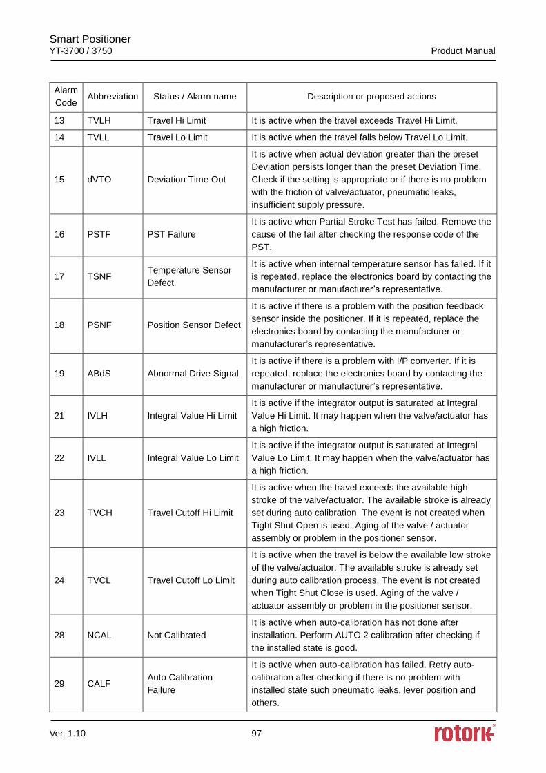
Smart Positioner YT-3700 / 3750 Product Manual
Ver. 1.10 97
Alarm
Code Abbreviation Status / Alarm name Description or proposed actions
13 TVLH Travel Hi Limit It is active when the travel exceeds Travel Hi Limit.
14 TVLL Travel Lo Limit It is active when the travel falls below Travel Lo Limit.
15 dVTO Deviation Time Out
It is active when actual deviation greater than the preset
Deviation persists longer than the preset Deviation Time.
Check if the setting is appropriate or if there is no problem
with the friction of valve/actuator, pneumatic leaks,
insufficient supply pressure.
16 PSTF PST Failure
It is active when Partial Stroke Test has failed. Remove the
cause of the fail after checking the response code of the
PST.
17 TSNF Temperature Sensor
Defect
It is active when internal temperature sensor has failed. If it
is repeated, replace the electronics board by contacting the
manufacturer or manufacturer’s representative.
18 PSNF Position Sensor Defect
It is active if there is a problem with the position feedback
sensor inside the positioner. If it is repeated, replace the
electronics board by contacting the manufacturer or
manufacturer’s representative.
19 ABdS Abnormal Drive Signal
It is active if there is a problem with I/P converter. If it is
repeated, replace the electronics board by contacting the
manufacturer or manufacturer’s representative.
21 IVLH Integral Value Hi Limit
It is active if the integrator output is saturated at Integral
Value Hi Limit. It may happen when the valve/actuator has
a high friction.
22 IVLL Integral Value Lo Limit
It is active if the integrator output is saturated at Integral
Value Lo Limit. It may happen when the valve/actuator has
a high friction.
23 TVCH Travel Cutoff Hi Limit
It is active when the travel exceeds the available high
stroke of the valve/actuator. The available stroke is already
set during auto calibration. The event is not created when
Tight Shut Open is used. Aging of the valve / actuator
assembly or problem in the positioner sensor.
24 TVCL Travel Cutoff Lo Limit
It is active when the travel is below the available low stroke
of the valve/actuator. The available stroke is already set
during auto calibration process. The event is not created
when Tight Shut Close is used. Aging of the valve /
actuator assembly or problem in the positioner sensor.
28 NCAL Not Calibrated
It is active when auto-calibration has not done after
installation. Perform AUTO 2 calibration after checking if
the installed state is good.
29 CALF Auto Calibration
Failure
It is active when auto-calibration has failed. Retry auto-
calibration after checking if there is no problem with
installed state such pneumatic leaks, lever position and
others.
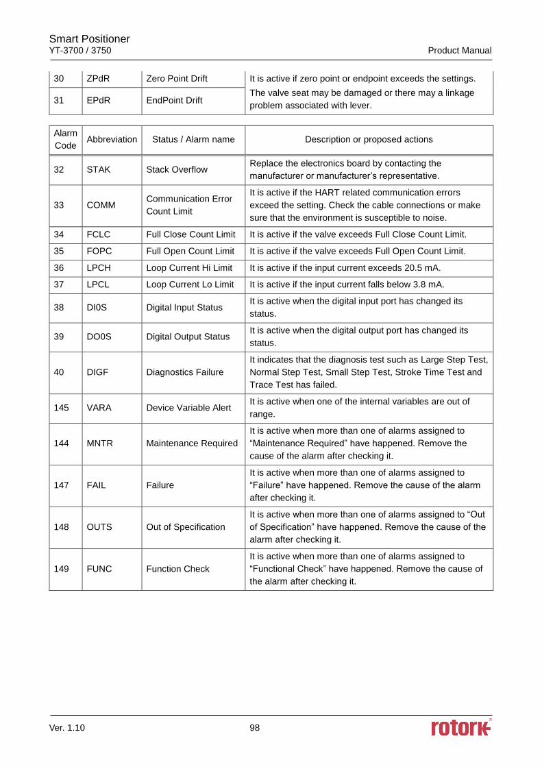
Smart Positioner YT-3700 / 3750 Product Manual
Ver. 1.10 98
30 ZPdR Zero Point Drift It is active if zero point or endpoint exceeds the settings.
The valve seat may be damaged or there may a linkage
problem associated with lever. 31 EPdR EndPoint Drift
Alarm
Code Abbreviation Status / Alarm name Description or proposed actions
32 STAK Stack Overflow Replace the electronics board by contacting the
manufacturer or manufacturer’s representative.
33 COMM Communication Error
Count Limit
It is active if the HART related communication errors
exceed the setting. Check the cable connections or make
sure that the environment is susceptible to noise.
34 FCLC Full Close Count Limit It is active if the valve exceeds Full Close Count Limit.
35 FOPC Full Open Count Limit It is active if the valve exceeds Full Open Count Limit.
36 LPCH Loop Current Hi Limit It is active if the input current exceeds 20.5 mA.
37 LPCL Loop Current Lo Limit It is active if the input current falls below 3.8 mA.
38 DI0S Digital Input Status It is active when the digital input port has changed its
status.
39 DO0S Digital Output Status It is active when the digital output port has changed its
status.
40 DIGF Diagnostics Failure
It indicates that the diagnosis test such as Large Step Test,
Normal Step Test, Small Step Test, Stroke Time Test and
Trace Test has failed.
145 VARA Device Variable Alert It is active when one of the internal variables are out of
range.
144 MNTR Maintenance Required
It is active when more than one of alarms assigned to
“Maintenance Required” have happened. Remove the
cause of the alarm after checking it.
147 FAIL Failure
It is active when more than one of alarms assigned to
“Failure” have happened. Remove the cause of the alarm
after checking it.
148 OUTS Out of Specification
It is active when more than one of alarms assigned to “Out
of Specification” have happened. Remove the cause of the
alarm after checking it.
149 FUNC Function Check
It is active when more than one of alarms assigned to
“Functional Check” have happened. Remove the cause of
the alarm after checking it.
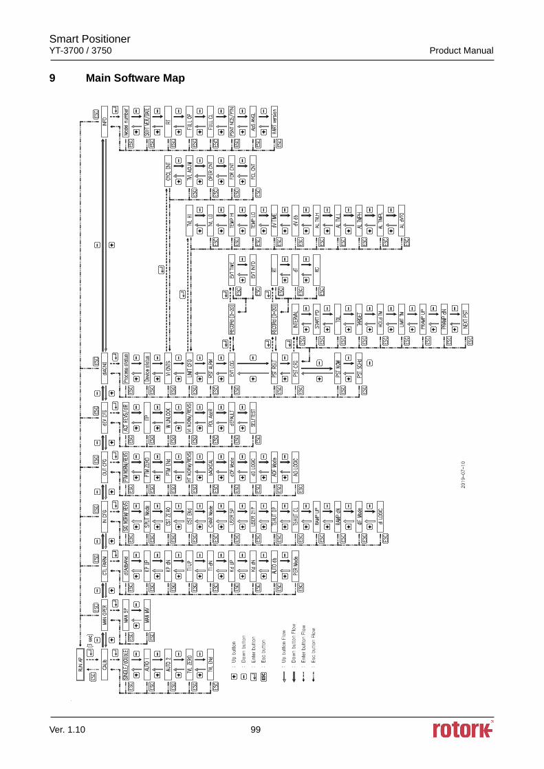
Smart Positioner YT-3700 / 3750 Product Manual
Ver. 1.10 99
9 Main Software Map
Smart Positioner YT-3700 / 3750 Product Manual
Ver. 1.10 100
Manufacturer: Rotork YTC Limited
Address: 81, Hwanggeum-ro, 89 Beon-gil, Yangchon-eup, Gimpo-si, Gyeonggi-do, South Korea
Postal code: 10048
Tel: +82-31-986-8545
Fax: +82-70-4170-4927
Email: [email protected]
Homepage : http://www.ytc.co.kr
Issued : 2020-01-02
Copyright © Rotork YTC Limited. All Rights Reserved.