smart optical ram for fast information management and analysis · smart optical ram for fast...
TRANSCRIPT

NASA ACRP GRANT NO. NAG2-1050
FINAL TECHNICAL REPORT
Smart Optical RAM for Fast Information
Management and Analysis
submitted to
NASA Ames Research Center
by
Hua-Kuang Liu, Ph. D.
Principal Investigator
Professor of Electrical Engineering
University of South Alabama
Mobile, Alabama 36688
Tel. (334)460-7516, Fax. (334)460-6028
E-mail: [email protected]
November 23, 1998
https://ntrs.nasa.gov/search.jsp?R=19990009321 2018-06-24T03:03:57+00:00Z
TABLE OF CONTENTS
I. Project Overview
1.1
1.2
1.3
1.4
1.5
Statement of Problem
Solution of the Problem
Potential ApplicationsInnovation of the Work
Concept Impact
II. Description of the Project
2.1
2.2
2.3
Project Objective
Theoretical backgroundResearch Results
"Massively parallel optical pattern recognition and retrieval
via a two-stage high-capacity multi-channel holographic
random-access memory system."
Acknowledgements
References
Figure captions
Appendix A: Invited Paper
"Translation Sensitive Adjustable Compact Optical Correlator"
Appendix B: US Patent Application
"A Large-Capacity Holographic Associative memory System"
Appendix C: Optical Engineering Paper
"Advanced ultra-high-capacity optical random access memory
and pattern recognition techniques"
Page
2
2
3
4
4
6
6
10
12
25
26
28
50
76
80
Smart Optical RAM for Fast Information Management and Analysis
I. Project Overview
1.1 Statement of Problem
Instruments for high speed and high capacity in-situ data identification, classification and
storage capabilities are needed by NASA for the information management and analysis of
extremely large volume of data sets in future space exploration, space habitation and utilization,
in addition to the various missions to planet-earth programs. Parameters such as communication
delays, limited resources, and inaccessibility of human manipulation require more intelligent,
compact, low power, and light weight information management and data storage techniques.
New and innovative algorithms and architecture using photonics will enable us to meet these
challenges. The technology has applications for other government and public agencies.
1.2 Solution of the Problem
In this NASA Advanced Concept Fellow Program, we have proposed and investigated a
totally new and innovative optical random-access memory (RAM) system. Comparing to the
digital RAM in electronic computers, the optical RAM has much broader capabilities. The
optical RAM can be used not only for the storage of an extremely large amount of information
and fast random-access to the data but also for pattern classification and interconnections in
future advanced computers.
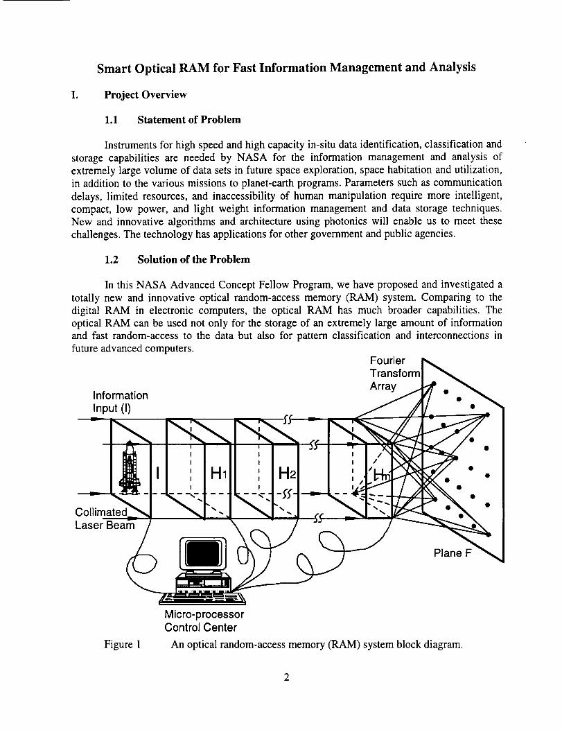
Information
Input (I)
Laser Beam
Fourier
Transform
Array
Plane F
Figure 1
Micro-processorControl Center
An optical random-access memory (RAM) system block diagram.
2

ThenewopticalRAM isconceptuallyillustratedin Fig. 1.Theinformationinput I in a2-D imageor dataformat is carriedby a collimatedlaserbeamandappliedthrougha sequenceofmultiple stagesof cascadedholographicoptical elements(HOE) and shutterarraysdenotedbythe H blocks. The HOE in H1 will divide and replicate the input I into an array of hlxhlidentical images.The shutterarray in H1 is electronicallycontrolledwhich can let any of the
(hl) 2 replicaof I passingthroughthe optical system.The subsequentH blocks have similar
functionsandcapabilities.Henceat the outputof theblock Hn, (hlh2.......hn)2 replicaof I willappearin a Fouriertransformarrayat planeF.For example,if 2 stagesof H areusedwith h1=9
andh2=5, (45)2= 2,025Fouriertransformsof I canbeobtainedat planeF. If 4 stagesof H are
usedwith h l=h3=9 andh2=h4=5,(9x5x9x5)2--4,100,625Fouriertransformsof I canbestoredatplaneF. If the input dataarepeople'sfaces,thenall thefacesof anyoneof mostof thecities intheworld canbememorizedin theoptical RAM. Furthermore,randomaccessibleretrievalcanbeachievedat the speedof light! The memorycanbeaccessedby simultaneousswitching theshutterarrays.
1.3 Potential Applications
In contrast to the conventional optical correlators that can process only one channel at a
given instant, the proposed optical RAM can memorize tens of thousands of channels of 2-D
information of on the order of megabytes and retrieve information accurately at the speed of
light. Partial information input can recall complete information from the optical RAM. These
unique abilities of the optical RAM allow it to be applied to many current fields of interest,
including parallel database search, image and signal understanding and synthesis, real-time
multi-sensory target recognition and classification, and parallel optical interconnections for
future computers. These areas are of importance to NASA's future space exploration, space
habitation and utilization, in addition to the various missions to planet-earth programs and many
commercial applications including fingerprints identification for police and FBI and optical
interconnections for future computers.
For purpose of demonstration, one example of these applications is illustrated in Fig. 2.
Fig. 2(a) shows how memorization in the optical RAM is accomplished by placing the objects as
represented by the satellite and space shuttle in the view of a video camera. Over tens of
thousands of 2-D data can be stored. Microprocessors may be used to control the random access
to any data set from the memory. After the optical RAM memorizes all the images presented to
it, it becomes smart. When input such as a partial and noisy space shuttle as shown in Fig. 2(b),
is presented to it, the smart RAM can recover and display at the output screen the perfectly
retrieved image. In addition, the optical RAM can be used to recognize input and tells us whether
it belongs to the memory. For example, if the fingerprints of FBI's most wanted criminals are
stored in the memory, the RAM can determine whether an arbitrary input fingerprint belongs to
one of the criminals. This can be done remotely and the optical RAM can make decision at the
speed of light!
3

In summary,a few potentialNASA andcommercialapplicationsaresummarizedbelow:
NASA Applications
a)b)c)d)e)f)g)
Planetary exploration in-situ data analysis and information screening
Space surveillance specific object identification and navigation guidance
Space image understanding and classification
Space station automated rendezvous and docking
Space habitation and utilization environmental evaluation and assessment
Navigation collision avoidance in Moon and Mars
Satellite repair, maintenance and sensing
Commercial applications
a)b)c)d)e)
Criminal fingerprints random access memory and retrieval for police
Security check of commercial building entrances
Automobile plate identification
Large capacity free space interconnection for future computers
Border patrol and illegal drug traffic prevention
1.4 Innovation of the Work
Comparing with existing technology can show the innovation. For example, the operation
of a digital computer requires that data can be stored and retrieved as desired, and information
can be put randomly into and out of each storage element as required. A digital RAM is used for
this purpose. However, according to Professor Jacob Millman of Columbia University, a major
disadvantage of the digital RAM is that it is volatile. Due to the fact that dynamic circuits are
exclusively used for large storage capacity, stored information is lost when the power is turned
off. The proposed optical RAM has some functions of a digital RAM but is non-volatile. When
the laser light is turned off, the memory remains in the hologram. Similar optical technology for
memory are limited to single channel operation with limited data throughput data processing
capacity, the proposed optical RAM has good sensitivity, high resolution, speed-of-light photon
processing, massive parallelism, accurate smart retrieval, and real-time operation capability.
1.5 Concept Impact
The optical RAM, which is quite different from the electronic RAM, displays a higher
level capability of optical multiplexing a 2D input and comparing it with many different
reference data sets, and can create an oscillatory optical resonance mode in which input variation
and error can be eliminated. As erasable optical recording materials such as the thermoplastic
material and photorefractive materials are used, the information will remain in the memory until
the writing of new information into the system. In addition to the conventional memory
capability similar to a digital RAM, it has the added capability of parallel pattern classification
for information management that the digital RAM does not have. For NASA, the impact of the
concept on increased automation and increased efficiency in information management based on
the optical RAM means that previously impossible missions are enabled.
4

Laser
Optical RAM
Input Micro-processorObjects Control Center
(a)
Optical RAM
Laser
J Iteration
Partial NoisyInput
Micro-processorControl Center
RetrievedNoise-free
Output
(b)
Figure 2. Example of the applications of an optical RAM. (a) Memory process;(b) Information retrieval.
II. Description of the Project
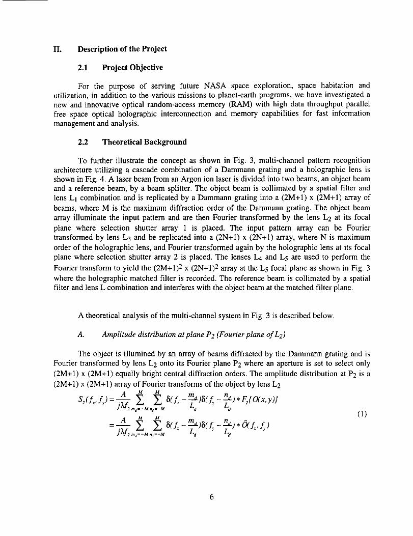
2.1 Project Objective
For the purpose of serving future NASA space exploration, space habitation and
utilization, in addition to the various missions to planet-earth programs, we have investigated a
new and innovative optical random-access memory (RAM) with high data throughput parallel
free space optical holographic interconnection and memory capabilities for fast information
management and analysis.
2.2 Theoretical Background
To further illustrate the concept as shown in Fig. 3, multi-channel pattern recognition
architecture utilizing a cascade combination of a Dammann grating and a holographic lens is
shown in Fig. 4. A laser beam from an Argon ion laser is divided into two beams, an object beam
and a reference beam, by a beam splitter. The object beam is collimated by a spatial filter and
lens L1 combination and is replicated by a Dammann grating into a (2M+l) x (2M+I) array of
beams, where M is the maximum diffraction order of the Dammann grating. The object beam
array illuminate the input pattern and are then Fourier transformed by the lens L2 at its focal
plane where selection shutter array 1 is placed. The input pattern array can be Fourier
transformed by lens L3 and be replicated into a (2N+l) x (2N+l) array, where N is maximum
order of the holographic lens, and Fourier transformed again by the holographic lens at its focal
plane where selection shutter array 2 is placed. The lenses L4 and L5 are used to perform the
Fourier transform to yield the (2M+l) 2 x (2N+l) 2 array at the L5 focal plane as shown in Fig. 3
where the holographic matched filter is recorded. The reference beam is collimated by a spatial
filter and lens L combination and interferes with the object beam at the matched filter plane.
A theoretical analysis of the multi-channel system in Fig. 3 is described below.
A. Amplitude distribution at pIane P2 (Fourier plane of L2)
The object is illumined by an array of beams diffracted by the Dammann grating and is
Fourier transformed by lens L2 onto its Fourier plane P2 where an aperture is set to select only
(2M+l) x (2M+l) equally bright central diffraction orders. The amplitude distribution at P2 is a
(2M+ 1) x (2M+ 1) array of Fourier transforms of the object by lens L2
S2(fx, fy ) a M M __L )5(fy _La) * Y)]2 ma=-Mna=-M d
(1)u M m n a
A E EiV2 m:-M.:-M
6

HolographicMatched Filter
SpatialFilter
L
L5 Selection
L4 Shutter Array 2
M HolographicLens
L2
L3M
Collimated
laser BeamBS
SpatialFilter Damman Selection
Grating Object Shutter Array 1
M
Figure 3 The experimental setup of a multi-channel pattern recognition architecture
utilizing a cascade combination of a Dammann Grating and a holographiclens.
where l is the wavelength of the laser, A is a constant associated with the input wave amplitude,
f2 is the focal length of lens L 2, and 1/L d is the periodic of the Dammann Grating in frequency
domain. Fn[] denotes the Fourier transform by lens Ln (n=l, 2 .... ),
O(f,,fy) = F2{O(x, y)}= j_ O(x, y)exp[-j2_(f,x+ f,.y)]dxdy (2)
where fx and fy are the special frequencies: fx=X2/(lf2) and fy=Y2/(If2), and (x2, Y2) are points in
plane P2. The amplitude distribution at P2 can also be expressed in terms of the position at plane
P2
7

s :-_ Y-_U2(x2, Y2) = 2, _f2' _'-f2"
_ A M _ md)5(y 2 _f2 na )-raa=-M na =-M
:V,
,6(2z, y_.a) (3)V_V2
Where
1 M M
Ma(xvy2)= (_'f2) 2 __, _., 8(x2-_.-_md)_(y2-_-_.n..,=-M.,=-M La Ld d)(4)
B. Amplitude distribution at Fourier plane of lens L3
A lens L 3 is placed at distance f3 from plane P2. Due to the input at plane P2, the
amplitude distribution at Fourier plane of lens L3 may be written as
I
s,(G, f,,) = _ F,:G(x2,y_)lA
- FJ Md(X 2, Y2)}" F3F2{ O(x, y)}
(5)
The amplitude distribution Eq. (5) can also be expressed in terms of the position at Fourier plane
of lens L3, that is
-- d, a: , ): )'O(-- Xr-- Y J)(v?(v,) .., ..,
(6)
where /l)a(f_,fy)= F3[Md(X, y)}.
C. Amplitude distribution at Fourier plane of the holographic lens
The holographic lens Fourier transforms the input U3(x3, Y3) to a (2N+l) x (2N+l) array
of spectrum onto its Fourier transform plane. The amplitude distribution is
8
Sh(f_vf,,,)-jV h _-_ 2 5(Ls L^m Lhm^=-N n_=-N
N N In n_
: A _ E E 5(fxs-'z_h)5(fy'- Lh )J(Ve )(V3 )( L ) m:-U,_=-N
A _y,)}X 3 ,
A N N
j(V,)(V,)(zA). ,. & L.
*FhFff Ma(xv Ye)} * F, Fff O(_f2 ,_)}
(7)
The amplitude distribution Eq. (7) can also be expressed in terms of the position at
Fourier plane of the holographic lens, that is
Uh(xh, Yh) = S (_'ff-_',"¢_")'V_V.
_ A 1 NN _- j(;_f2)(Zf3)(M ) (kfh), __, ___ _(x, - mh)_(y , -- n,)rtl_=- N n_ =- N
•M ,-f' x ,_.h., ,, 0(---_ __.A_a, fh ' L :h" _,f2A xh' _,LL y^)
=- A Mh(Xh,Yh).Ma(__fhXh,_fhyh).-f_.._X hj(_.f2)(_.L )(_,fh) - O(- xf2f h ,
(8)
wherefh is the focal length of the holographic lens, l/Lh is the periodic of the holographic lens in
frequency domain, and
u u _._I Z Z _)(xh- m_,)_)(y h kfhMh (xh' Yh ) - (Tvfh)2 ,,,:-N,,:-u -"-_ nh )
(9)
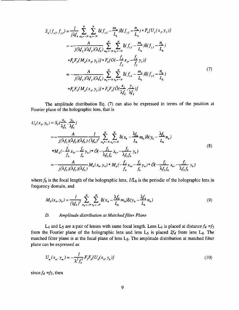
D. Amplitude distribution at Matched fiIter Plane
L4 and L5 are a pair of lenses with same focal length. Lens L4 is placed at distance f4 =f5
from the Fourier plane of the holographic lens and lens I-,5 is placed 2f4 from lens L4. The
matched filter plane is at the focal plane of lens L5. The amplitude distribution at matched filter
plane can be expressed as
1U,,,(x,,,, y,,,) =-_-"7"_2 FsF4{Uh(xh, Yh)]
t_ J4(10)
since f4 =f5, then
9

1
U_(x_. ym)=--_Uh(-x...-Y,_)
A-- J(kf2)(_f3)(_'fh)(_f4) 2 Mh(-x_'-Ym) * Me( f-}'Jhx,.. Ym),O, L x f_L ,
(ll)
where (x m, Ym) is the position at matched filter plane. It can be seen that the amplitude
distribution at the matched filter plane is a (N x N) with (M x M) array of the Fourier transforms
of the object
6(L,f,)= F2[O(x,Y)}= IIO( x, y)expt-j2rt(f_x + f_y)ldxdy
with
f_ _....fd._x andfy =---_y,_- V,A " V2A
E. Recording of the Holographic Matched fiIter
In the recording of the holographic matched filter, two selection arrays are placed at the
plane P2 and at the Fourier plane of the holographic lens, respectively. The selection arrays are
set that only one order from the Dammann grating or the holographic lens is selected to go
through while other orders are blocked. Once the order (ml, nl) from Dammann grating and the
order (m2, n2) from holographic lens are selected, the amplitude distribution at the matched filter
plane, or Eq. (11), becomes
A 5(-x_ _--_fmQ_(-y m _'-_tn'U_(x,..Y,.)=j(Tkf2),O_f_)O_fh)30_f4)2 - Lh - Lh 21
*5( x m-Lam,)o_fhy,,,- _ n,) O(La _'Lfh "' _fh y-)
_ axf_ _(_Xm_Xfhm2)_(_ym_Xfhn )j(_L)_(_L)"(V,)_ L_ L_
*5(Xm -_f-_m )_(Y,,-_Jhn, )*O( fj .f_-g-_ Ym)
(12)
2.3 Research Results
The latest results of the research are included in the preprint of a manuscript as shown
below. Other results including papers published and patent application are included in the
appendixes.
10

Massively parallel optical pattern recognition and retrieval
via a two-stage high-capacity multi-channel
holographic random-access memory system
Luzhong Cai*
Hua-Kuang Liu, FELLOW SPIE
University of South Alabama
Department of Electrical and Computer Engineering
Mobile, Alabama 36688
E-mail: lcai @ usamail.usouthal.edu
*Permanent address: Shandong University, Department of Optics, Jinan, 250100, China
11

Abstract. The multi-stage holographic optical random-access memory (HORAM) system
reported recently by Liu et al provides a new degree of freedom for improving the storage
capacity. In this paper we further presented theoretical and practical analysis on the HORAM
system with experimental results. Our discussions included the system design and geometrical
requirements, its applications for multi-channel pattern recognition and associate memory, the 2-
D and 3-D information storage capacity, and the multi-channel image storage and retrieval via
Vander Lugt correlator (VLC) filters and joint transform holograms. A series of experiments
have been perforrried to demonstrate the feasibility of the multi-channel pattern recognition and
image retrieval with both of the VLC and joint transform correlator (JTC) architectures. The
experimental results with as many as 2025 channels have shown good agreement with the
theoretical analysis.
Subject terms: multi-stage holographic optical random-access memory system; holographic
storage; optical pattern recognition; image storage and retrieval; optical information processing.
12
1 Introduction
Opticaldatastorageandpatternrecognitionaretwo importantandrelatedareasin modemoptics.
For thepurposeof opticalpatternrecognition,a varietyof architecturesandtechniqueshavebeen
developed,which aremainlycategorizedinto VanderLugt correlator(VLC)TM and joint transform
correlator (JTC) 5-8systems. Optical data storage offers inherent 2-D parallelism and high speed
processing. It may enable one to construct a holographic database with a large number of image
templates optically accessible and applicable for
recognition, image retrieval, and associate memory.
different applications including pattern
In order to increase the image storage and
recognition capability of a system, several methods have been proposed and experimentally
demonstrated. These include the composite filter synthesis 9'° and multiplexing techniques with the
use of a volume recording element'"2°. The latter approach has been considered as one of the most
successful and promising techniques for data storage. For example, Heanue et al demonstrated the
storage and retrieval of digital data using a volume hologram _2, Mok reported that over thousands
of holograms can be stored in a lithium niobate crystal via angular multiplexing '3, and Pu et al
reported the storage of up to one thousand holograms at a single location using the DuPont 100-
l.tm-thick photopolymer 2°. In these techniques, either the volume effect of a 3-D recording device
or the one-stage spectrum multiplexing is used to enhance the storage capacity of a given system.
More recently, Liu et al presented a multi-stage holographic optical random-access memory
(HORAM) system 2_'22, which has advantages including higher storage capacity over a single stage
system.
In this paper we will discuss the design principles of the multi-stage HORAM system for its
practical applications. We will introduce a few architectures for different applications and, for the
first time, present new and more detailed experimental demonstration results of multi-channel
13

patternrecognitionandreconstructionwith theuseof a two-stageHORAM systemincludingVLC
and JTC arrangements.The resultshaveverified the feasibility and usefulnessof a multi-stage
multi-channelHORAM system.
2 Theoretical analyses
2.1 Geometrical considerations for spectrum array generation and separation
A multi-stage HORAM system is composed of several stages cascaded in tandem. The use of
many stages in a system can greatly increase the spectrum multiplexing capacity, but it also
introduces the complication in the interconnection between any two succeeding stages. In order to
ensure that all the spectra of different orders in the final spatial spectrum plane are properly
separated, the optical arrangement of a HORAM system should satisfy certain geometrical
requirements. In the following we will discuss these requirements for a two-stage HORAM
system.
The working principle of a two-stage HORAM system may be schematically expressed in
Fig. 1, where (a), (b) and (c) are the optical setup and the spectral distributions in planes F and H,
respectively. The light from a point coherent source, S, becomes a plane wave after passing
through collimator L_, and then illuminates the object transparency, O, which is in close contact
with a Dammann grating, G. The first spectrum array is obtained at the back focal plane F of lens
L2. The grating G may produce many diffraction orders in plane F. By inserting a rectangular
opening aperture we can select only MxM central diffraction orders and block the higher orders. A
combination of lens L3 and a multi-focus hololens, Lh, images plane F onto plane H. In plane H the
spectrum is further multiplexed to a (MxM)x(NxN) array, where the NxN multiplexing is
produced by the hololens.
14

If we assumetheDammanngratinghasthesamespatialfrequencyVdin thex andy directions,
the lengthof onesideof theMxM spectrumarrayin planeFcanbedecidedby
D: = D_ = D_, = M,;t,f2Vd , (1)
where _, is the wavelength of the laser, and f2 is the focal length of lens Lz. This pattern is
magnified in plane H by a factor
fhA - (2)
f3'
and the hololens I__ further replicates the magnified M x M spectrum array to N x N arrays with
a spacing
Dh = _,Vh fh, (3)
where f3 and fh are the focal lengths of L3 and l_,h, respectively, and Vh is the spatial frequency of
the hololens. Obviously, in order to separate different orders in plane H, we need
Dh > AD:, (4)
that is
f,vh > M ''Vd, (5)
f3
or, if we use the parameter A,
A < fhVh (6)Mf2Vd
Actually the planes F and H are not necessarily placed in the front focal plane of L3 and back
focal plane of Lh, respectively. What we need here is the multiple imaging function, which can
be performed by either a single multi-focus hololens or a combination of a multi-focus hololens
15

and anotherconventionallens,asshownin Fig.2 (a) and (b).
from F to H maybewritten
dhA-
d t
The requirements similar to Eqs. (5) and (6) may then be written as
vh > M f2 va
d/
and
In both cases the magnification
(7)
(8)
dhvhA < _, (9)
Mf2va
or equivalently
> Mflva.d: (10)V^
We can see that the changes here are the substitutions of t'3 and fh by df and dh, respectively.
We may use Eq. (10) to adjust the magnification of the imaging system to ensure spectrum
separation. In the exact matching case where the equal sign is used in all the above expressions,
we will obtain an equal spacing (N x N) x (M x M) spectrum array in plane H.
The size of the M x M spectrum array in plane F has been given in Eq. (I). In case of exact
matching, the (N x N) x (M x M) spectrum array in H has the size D x D, where
D = N-"D:'4_ = MN2f_va d--L (11)d/ d/
The use of a Dammann grating sets a resolution limit on the input image. The maximum
transitive spatial frequency in object plane is half of yd. Increasing Vd may improve the object
resolution, but it also yields a larger spectrum size D as indicated by Eq. (11). In practice, D has
16

a limit, thereforeall the parameterssuchas M, N andvd are limited to a certainrangeby the
availabilityof usablespace.
2.2 Multi.channel pattern storage and recognition with VanderLugt correlator
An architecture of a multi-channel VanderLugt-correlator-based two-stage HORAM system is
shown in Fig.3, where F_ and F2 are the first and second spectrum planes respectively. An
additional imaging arrangement from plane F2 to plane H is used here for the convenience of
placing the shutter array in plane F2 We may record MNxMN different spectra in plane H by
using two shutter arrays at planes FI and F2, respectively, only a single aperture in each shutter
array is open when each input image is applied. Assume the same reference beam is used in the
recording process for all the input images and all the apertures of the shutters are opened
simultaneously in the correlation step. Applying an arbitrary input Oij among the memorized
images, we will obtain one autocorrelation term and (M2N2-1) crosscorrelation terms in the
center of plane P (i.e., the focus of the reference beam). The resultant correlation output is
MN MN
uc =o,j ®o,j + 2o.. ®o,,. (12)m,n=l k,l=l
m.n,k,l_i.j.i,j
where ® denotes correlation. Although the first term in the above equation is considerably larger
than any other, the combination of the other terms will be larger than the first one due to the
large number MZN 2. Therefore this setup is not usable for large capacity pattern recognition.
There are two remedying means to circumvent this problem.
First, we may open the shutter aperture sequentially for a given input pattern while
observing the correlation output in plane P. The position of the opened aperture corresponding
17

to the maximum correlation reveals the specific input object. Evidently we must scan the whole
shutter aperture array for each input image, and it takes a minimum time period of
T= M2N2'r, (13)
where • is the time required for the detection of the correlation peak. This time is dependent on
some practical factors such as the recording material and the detecting device. If a CCD of a
response time of 10 ms is used for correlation peak detection, T would be 10 seconds for
MZN2=10 3. This should be acceptable for some practical applications, but not fast enough for
high-speed recognition and high data transfer operation.
An effective approach to solve this problem is to use the reference beam angular
multiplexing technique. In this method we employ a different angle for each reference beam
with each shutter aperture which is opened successively for each different input image in the
recording process. The different reference beams form a focal array in plane P. In the correlation
process all the shutter apertures are opened simultaneously for a given input, and the location of
the brightest spot in P identifies the recognized input pattern. This technique can work much
faster compared to the fixed reference beam method, but it is at the expense of using a
complicated angle-adjusting recording system.
In the above analysis we have assumed that a planar hologram is used. In fact we may also
use 3-D holographic recording materials such as the photorefractive crystals _3for making the
matched filters. The volume effects of a 3-D recording material enable us to realize angular
multiplexing recording for each individual spectrum position. This property adds one more
dimension to the storage capacity of the device, which may be estimated as follows.
For a Dammann grating with spatial frequency Vd, the minimum resolvable size in the object
plane is 1/vd, and the information amount per binary input page is (DoVd)2 bits, where Do is the
18

dimensionof input image(assumeDox=Doy= Do). Since a 2-D recording plate can store (MN) 2
images, the storage capacity should be
C=(MN):(DoVd) 2 (14)
bits, provided the lens aperture is large enough to transmit the spatial frequency yd. On the other
hand, for a 3-D device, there may be KxL holograms recorded by angular multiplexing for each
spectrum position, where K and L are the angular changes in x and y directions respectively.
Consequently the storage capacity is increased up to
C_ = (MN)2 KL(DoVd )2 (15)
bits. The values of K and L are mainly determined by the thickness of the crystal. Other
limitations to MN and KL are the dimensions of the recording device and related optical
elements.
For an example, assume Do=25 mm, v_=15/mm, M=9, N=5, then the storage capacity of this
2-D recording system is C=2.8x108 bits. For making sufficient spectra separation in the 3-D
recording with a crystal, we may reduce MN to, for instance, 4x4-16, and take a reasonable
value of KL to be 10 2 ~ 103 , the resultant storage capacity Cv is 3.6x10 9 - 10_°bits for a crystal of
1 cm 3 . In comparison, the best result obtained recently by IBM using a single stage system with
a photorefractive crystal 23 is 8.5×10 7 bits/cm 3. Hence, the multi-stage architecture can provide a
new degree of freedom for improving the storage capacity.
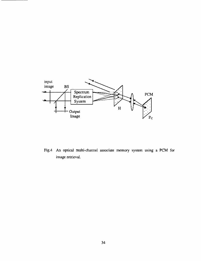
2.3 Multi-channel associate memory
Conceptually an associate memory may be realized with the use of a nonlinear threshold element
for feedback retrieval via a phase conjugate mirror (PCM). A viable architecture is shown in
19

Fig.4 wherethe multi-stageHORAM systemis simplified asa spectrumreplicationsystem.A
PCM is locatedin planePc andeachfilter in planeH is sequentiallymadefor a differentobject
andwith a different referenceangle. Whena partial imagecorrespondingto one of the stored
imagesis appliedto the input, a bright spot will appearat a properposition (the focus of its
recordingreferencebeam)in planePc. As a nonlinear and feedback device, the PCM reflects
only this beam and suppresses all other beams. The reflected light will form a plane wave,
conjugate to the original reference beam, and then generate a more complete image at the output
plane via a beam splitter.
Although this concept is simple, the practical limitation seems to be the availability of a high-
quality PCM with an effective aperture large enough to cover the whole correlation array.
2.4 Multi-channel joint transform hologram and image retrieval
The basic concept of making joint transform hologram (JTH) in a multi-channel system is
illustrated in Fig.5 (a), where two input images are placed side by side in plane Pin. Their joint
transform spectrum, which appears at the central region of the Fourier plane H, is recorded in a
holographic medium.
With the use of a multi-stage HORAM system for spectrum replication, a multi-channel JTH
can be made, where each element hologram in one position of the spectrum array corresponds to
a specific pair of input images. As many as (MN) 2 image pairs can be recorded in a 2-D
holographic medium. This multi-channel JTH may then be used for joint transform correlation
(JTC) or image retrieval. For the purpose of JTC, we can use a plane wave to illuminate the JTH
and obtain two correlation terms at the two opposite sides of the output plane located at the back
focal plane of a Fourier transform lens behind the JTH. Since the location of the correlation spot
20
is only determinedby thespatialseparationbetweenthetwo input imagesandindependentof the
elementlocationin theJTH, the correlationoutputsof all the JTH elementsoverlap if they are
illuminated simultaneously.To avoid this effect, the JTH elements should be scanned
successively(oneby one)byusinganelectricalshutterarraysystem.
The abovescanningtechniqueis also applicablefor imageretrieval. In this casewe store
(MN)2 imagepairs (a, bj) ( i,j=l - MN) at differentpositionsof thehologramH, andthen input
one imagea_and scanall the elementsin the JTH. When the JTH element(i,j) is open,the
reconstructedimagebjappearsat theoutputplaneasshownin Fig.5(b).
As we indicatedabove,althoughthesuccessivescanningrequirementmay seta limit on the
operation speed, the use of a high-speeddetector will decreasethe operation time and
consequentlyincreasethedataprocessingspeed.
3 Experimental demonstrations
3.1 Geometrical parameters of the optical setup
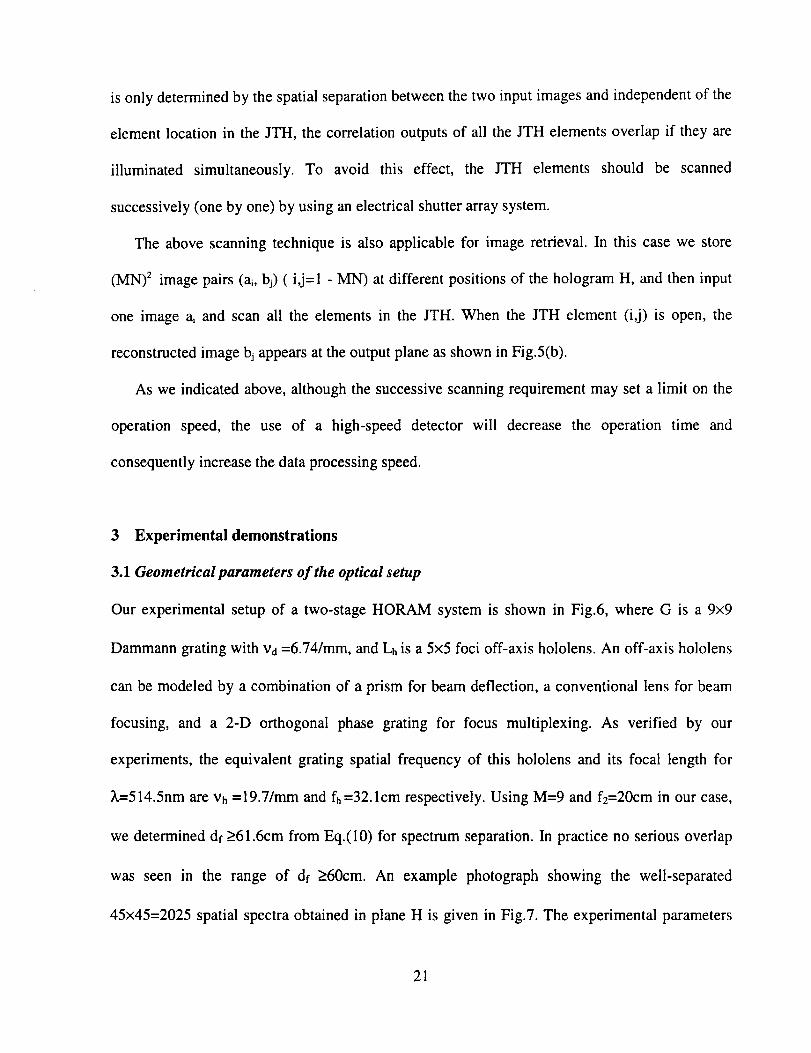
Our experimental setup of a two-stage HORAM system is shown in Fig.6, where G is a 9x9
Dammann grating with Vd =6.74/mm, and Lh is a 5×5 loci off-axis hololens. An off-axis hololens
can be modeled by a combination of a prism for beam deflection, a conventional lens for beam
focusing, and a 2-D orthogonal phase grating for focus multiplexing. As verified by our
experiments, the equivalent grating spatial frequency of this hololens and its focal length for
_.=514.5nm are vh =19.7/mm and fh =32.1cm respectively. Using M=9 and fe=20cm in our case,
we determined df >61.6cm from Eq.(10) for spectrum separation. In practice no serious overlap
was seen in the range of df >_60cm. An example photograph showing the well-separated
45×45=2025 spatial spectra obtained in plane H is given in Fig.7. The experimental parameters
21

we measuredunderexactmatchingcondition are df=61.5cm,dh=69.5cm, Df = 6.3 mm, and
D=36.6 mm. From these parameters we have (1/df +1/dh )-i =32.6cm, and the Eqs. (1) and (11)
give Df=6.24mm and D=35.3mm. These results have shown a good agreement between our
theoretical predictions and experimental measurements.
3.2 Multi.channel pattern storage and recognition
To verify the feasibility of the two-stage HORAM system for pattern storage and recognition, the
optical setup shown in Fig.6 was used to make the multi-channel VanderLugt filters. The light
source is an Ar ÷ laser delivering about 0.8w power at 514.5nm. The test images are two letters, S
and C, as shown in Fig.8. A plane wave is incident normally upon the combination of the object
transparency and the Dammann grating. At plane F a square aperture is used to let only the
central 9x9 array to pass through. After multiple imaging via the 5x5 foci hololens, we get the
second spectrum array in plane H with 2025 individual and spatially-separated spectra. A plane
reference beam is introduced to record the filters. The recording position in plane H may be
chosen by using two circular apertures in planes F and H to pass only the selected spectrum
order. First we select the (0,0) order in plane F and (-1,-1) order in plane H, the recording
medium used is a Kodak 649F plate. Two filters were made with input letter S and C (one letter
for each) respectively, and the exposure time is about 1/5 second. The correlation results with
these two filters are shown in Figs. 9 and 10. Figure 9 corresponds to filter #1 made with letter S,
where the left and right are autocorrelation for input S and crosscorrelation for input C,
respectively. Obviously the former is much stronger than the latter, and their intensity ratio is
about 6 to 1. Figure 10 shows similar results for filter #2 made with letter C, the autocorrelation
is about 8 times stronger than the crosscorrelation.
22

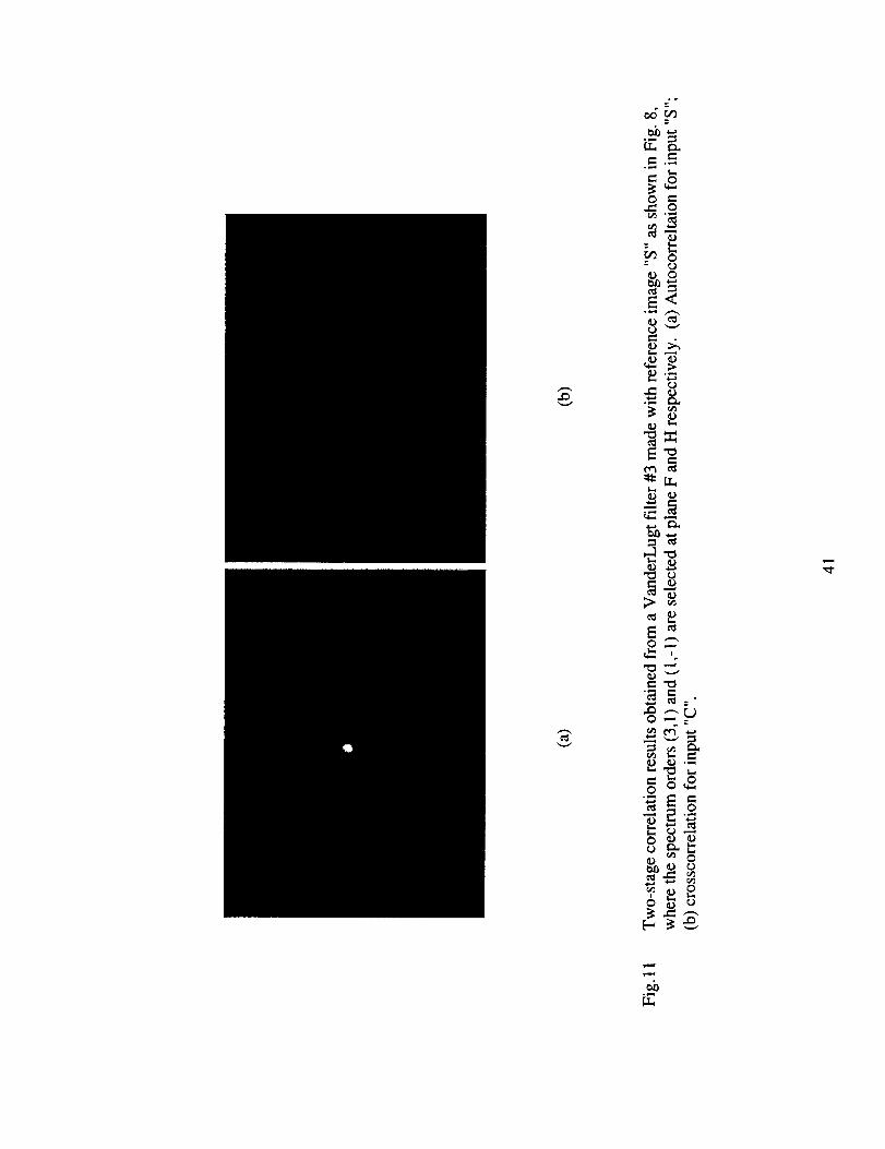
To test the recognitioncapability of any non-centralspectrumorder, we next selectedthe
(3,1)orderin planeF and(1,-1)orderin planeH to recordfilters #3 and#4 for the input images
S andC successively.TheRussianmadeFPR holographicplateswere used with an exposure
time of approximately1.5seconds.The correspondingcorrelationresultsareshownin Figs.11
and 12 for the two filters respectively.We can still clearly see that the intensity of
autocorrelationis much higher than that of the crosscorrelationin each case.So if a proper
thresholdintensityis chosen,the input patterncanbe recognizedwithout anydifficulty, andall
the2025channelscanwork well.
3.3 Image retrieval with multi-channel VanderLugt filters and JTHs
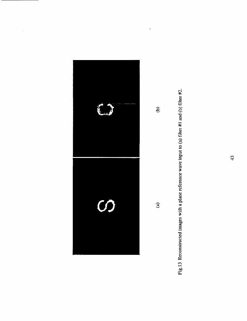
In order to test the image retrieval capability of the two-stage multi-channel VanderLugt filters,
we used a plane wave to illuminate the four filters we recorded one by one. The reconstruction
results are shown in Fig.13 for filters #1 and #2 and in Fig.14 for filter #3 and #4, respectively.
In each case we can clearly recognize the retrieved image, letter S or C. The reconstructed
images in Fig. 14 have lower signal-to-noise ratio than those in Fig. 13, because filters #3 and #4
are made with off-axis spectrum orders in both planes F and H. These orders are weaker than
those chosen from the central order in plane F and off-axis order in plane H.
We have also made some JTHs at different spectrum orders to verify the retrieval feasibility.
Due to the low diffraction efficiency in our experiment (only amplitude holograms were used)
and interference of the strong direct image with reconstructed pattern, the retrieved images with
a two-stage HORAM system are very noisy, weak, and difficult to record. In the following we
only present experimental results obtained with the JTHs recorded in the first spectrum plane F
(the 9x9 array).
23

Thefirst JTH wasmadein the architectureof Fig.5 with the lettersC andE, shownin Fig.15
astheinput imagepair.Thespectrumorderwasarbitrarily chosenas(-4,3).In thereconstruction
step,if the input is letterC, we simultaneouslyobtainasshownin Fig.16 (a)a strongaddressing
imageof letterC anda weakretrievedimageof letterE at theoutputplane. WhentheletterE is
usedastheinput, theoutputis shownin Fig.16(b) wherea strongE anda weakreconstructedC
canbeseensideby side.
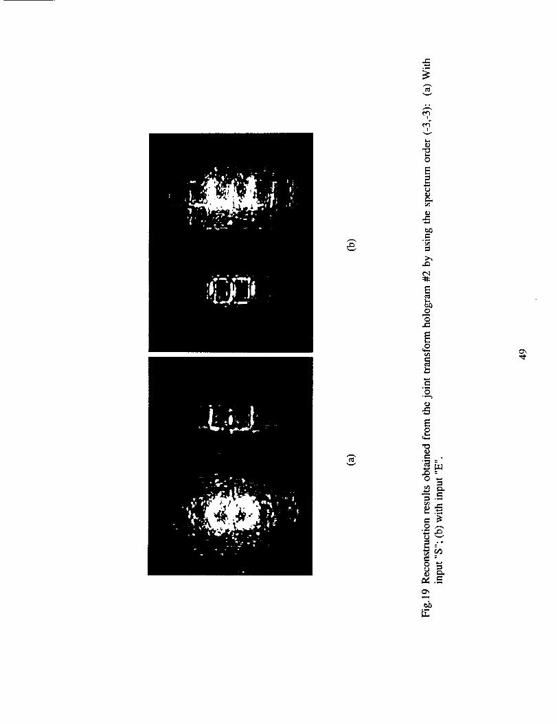
FurtherwemadethesecondJTH with input imagepair of lettersSandE asshownin Fig.17.
In this recordingprocesswe did not block any spectrumin planeF so that all the 9×9 JTH
elementswere recordedat the sametime. In the reconstructionstep we have obtainedthe
retrievedimageby usinganyoneJTHelement.As examples,wepresenttheexperimentalresults
obtainedwith theJTH of order(4,-2) in Fig.18and theJTH of order (-3,-3) in Fig.19. In each
photowe canclearly seethe reconstructedimagebesidesthestrongdirect image,regardlessof
which oneof the imagepair is usedastheinput.Theseresultshaveshownthat all the individual
channelscanwork effectivelyandindependently.
4 Conclusion
Based on the multi-stageHORAM systemreported by Liu et a121, we have made more
theoretical and practical analysison the requirementsof its geometricalparametersand its
optical architecture constituents,its applications in multi-channel pattern recognition and
associatememory,the 2-D and 3-D informationstoragecapacity,andthe multi-channelimage
storageandretrievalviaVLC filters andjoint transformholograms.A seriesof experimentshave
beenperformedto demonstratethefeasibilityof themulti-channelpatternrecognitionandimage
retrievalwith bothof theVLC andJTC architectures.The experimentalresultswith asmanyas
2025channelshaveshowngoodagreementwith thetheoreticalanalysis.We havediscussedthe
24

potentialapplicationsof thesystemfor large-capacitypatternstorage,recognition,andretrieval.
The useof fast-responseand low-noiserecordingmaterialsand detectingdeviceswill greatly
improvetheperformanceof thesystemfor practicalapplications.
Acknowledgments
This research work has been supported by the Advanced Concepts Research Program, the
National Aeronautics and Space Administration Grant No. NAG 2-1050 awarded to the
University of South Alabama and administrated by the Ames Research Center. Helpful
discussions with Jacob Barhen, Neville Marzwell, Charles Gary, and John Downie are hereby
acknowledged.
25
References
1. A. VanderLugt, "Signal detection by complex spatial filtering," IEEE Trans. Inf.Therory, IT-
10, 139-145 (1964).
2. D. Casasent and D. Psaltis, "Position, rotation and scale invariant optical correlation,"
Appl.Opt. 15, 1795-1799 (1976).
3. J. L. Homer and P. D. Gianino, "Phase-only matched filtering," Appl.Opt. 23, 812-816
(1984).
4. L. Cai, Y. Jin, S. Zhou, P. Yeh, N. Marzwell, and H. K. Liu, "Translation sensitivity
adjustable compact optical correlator and its application for fingerprint recognition,"
Opt.Eng. 35, 415-422 (1966).
5. C. S. Weaver and J. W. Goodman, "A technique for optically convolving two functions,"
Appl.Opt. 5, 1248-1248 (1966).
6. F. T. S. Yu and X. J. Lu, "A real-time programmable joint transform correlator,"
Opt.Commun. 52, 10-16 (1984).
7. B. Javidi and C. J. Kuo, "Joint transform image correlation using a binary spatial light
modulator at the Fourier plane," Appl.Opt. 27, 663-665 (1988).
8. L.Z. Cai, Y. R. Wang, and H. Wang, "High efficiency hybrid joint transform correlator with
preprocessed input image and replicated binary spectrum array," J.Modern Optics, 44, 1197-
1204 (1997).
9. D. Casasent, "Unified synthetic discriminant function computational formulation," Appl.Opt.
23, 1620-1627 (1984).
26

10.B. V. K. V. Kumar, "Tutorial surveyof compositefilter designfor optical correlators,"
Appl.Opt.31,4773-4801(1992).
11.N. V. Kukhtarev, V. B. Markov, S. G. Odulov, M. S. Soskin, and V. L. Vinetskii,
"Holographic storagein electroopticcrystals,I. Steadystate,"Ferroelectrics22, 949-964
(1979).
12.J.F.Heanue,M. C. Bashaw,andL. Hesselink,"Volume holographicstorageandretrievalof
digital data,"Science265(5173),749-752(1994).
13.F. H. Mok, "Angle-multiplexedstorageof 5000hologramin lithium niobate,"Opt.Lett.18,
915-917(1993).
14.S.Yin, H. Zhou,M. Wen, Z. Yang,andF. T. S.Tu, "Wave-lengthmultiplexedholographic
storagein a sensitivephotorefractivecrystal using a visible light tunable diode laser,"
Opt.Comm.101,317-321(1993).
15.P. A. Mitkas and L. J. Irakliotis, "Three-dimensionaloptical storage for database
processing,"J.Opt.MemoriesNeuralNet.3, 87-98(1994).
16.J.H. Hong.I. McMichael,T. Y. Chang,W. Christian,andE. G. Paek,"Volume holographic
memorysystem:Techniquesandarchitectures,"Opt.Eng.34,2193-2203(1995).
17.J. R. Wullert II and Y. Lu, "Limits of capacityanddensityof holographicstorage,"Appl.
Opt.33,2192-2196(1994).
18.F. T. S. Yu and S. Yin, "Thick Volume photorefractivecrystal wave-length-multiplexed
reflection-typematchedfilter," OpticalMemoryNeuralNetworks3, 207-214(1994).
19.L. Z. Cai, Y. R. Wang, and H. K. Liu, "Moving target recognition and tracking with
photorefractivejoint transformcorrelator,"Proc.SPIE,2896, 189-196(1996).
27

20.A. Pu, K. Curtis, and D. Psaltis, "Exposure schedulefor multiplexing holograms in
photopolymerfilms," Opt.Eng.35, 2824-2829(1996).
21.H. K. Liu, Y. H. Jin, and N. I. Marzwell, "Advancedultra-high-capacityoptical random
accessmemoryandpatternrecognitiontechniques,"Opt.Eng.37,779-788(1998).
22.D. Gregory,G. Duthie, andH. K. Liu, "Large memory real-timemultichannelmultiplexed
patternrecognition,"Appl.Opt. 23,4560-4570(1984).
23. IBM HolographicOptical Team,"Holographic storagepromiseshigh datadensity,"Laser
FocusWorld, 32. 81-93(1996).
Figure Captions:
Fig. 1 Schematic diagram of a two-stage HORAM system. (a) Optical architecture; (b) spectrum
distribution in plane F; (c) spectrum distribution in plane H.
Fig.2 Two configurations for adjusting the magnification between planes F and H.
Fig.3 The optical architecture of a two-stage HORAM system.
Fig.4 An optical multi-channel associate memory system using a PCM for image retrieval.
Fig.5 Multi-channel joint transform hologram: (a) Recording process; (b) reconstruction
process.
Fig.6 Experimental setup for a two-stage multi-channel HORAM system.
Fig.7 An example photograph showing 2025 well-separated spatial spectra obtained by two-
stage spectrum multiplexing.
Fig.8 Input images for VanderLugt matched filter fabrication.
28

Fig.9 Two-stagecorrelationresultsobtainedfrom a VanderLugtfilter #1 madewith reference
image"S" as shownin Fig.8, wherethe spectrumorders(0,0) and (-1,-1) areselectedat
planeF andH respectively.(a)Autocorrelationfor input "S"; (b) crosscorrelationfor input
IICIl j
Fig.10 Two-stage correlation results obtained from a VanderLugt filter #2 made with reference
image "C" as shown in Fig.8, where the spectrum orders (0,0) and (-1,-1) are selected at
plane F and H respectively. (a) Autocorrelation for input "C"; (b) crosscorrelation for
input "S".
Fig. 11 Two-stage correlation results obtained from a VanderLugt filter #3 made with reference
image "S" as shown in Fig.8, where the spectrum orders (3,1) and (1,-1) are selected at
plane F and H respectively. (a) Autocorrelation for input "S"; (b) crosscorrelation for input
IICII "
Fig.12 Two-stage correlation results obtained from a VanderLugt filter #4 made with reference
image "C" as shown in Fig.8, where the spectrum orders (3,1) and (1,-1) are selected at
plane F and H respectively. (a) Autocorrelation for input "C"; (b) crosscorrelation for
input "S".
Fig. 13 Reconstructed images with a plane reference wave input to (a) filter #1 and (b) filter #2.
Fig. 14 Reconstructed images with a plane reference wave input to (a) filter #3 and (b) filter #4.
Fig. 15 Input image pair for the fabrication of joint transform hologram #1.
Fig.16 Reconstruction results obtained from the joint transform hologram #1 by using the
spectrum order (-4,3): (a) With input "C"; (b) with input "E".
Fig. 17 Input image pair for the fabrication of joint transform hologram #2.
29

Fig.18
Fig.19
Reconstructionresultsobtainedfrom thejoint transformhologram#2 by using the
spectrumorder(4,-2): (a)With input "S"; (b) with input "E".
Reconstructionresultsobtainedfrom the joint transform hologram #2 by using the
spectrumorder(-3,-3): (a)With input "S"; (b)with input "E".
30

Lt OG L2 F L3 I_¢ H
II
(a)
MxMeeeo oele
eJee oeel
eeee eeee
eeem eeee
eeem eeee
eeee eeee
eeeo *ee*
*oee eeee
F
(b)
(M x M) x (N x N)
I I I I L
3DD
3E3D
-J L.J
3[3[3
3E3DDhb--
H
(c)
Fig. 1 Schmetic disgram of two-stage HORAM system. (a) Optical architecture;
(b) spectrum distribution in plane F; (c) spectrum distribution in plane H.
31

F I__ H
df _ dh(a)
F L h. H
df _ dh "'_l
(b)
Fig. 2 Two configurations for adjusting the magnification between planes F and
H.
32

©
input
image B S rumL__,____ I / I Snect
Replication _-'_ System
| t Output H ]'.Y
Image
Fig.4 An optical multi-channel associate memory system using a PCM for
image retrieval.
34

t; L... i spectrum
ai _ i 'ra I • •rephcatton14, II-I-- t systembj_
Pin(a)
. _ Ispec_m
- I system
Pin
(b)
H
(i,j)
H0
a bJ
Pout
Fig. 5 Multi-channel joint transform hologram:
reconstruction process.
(a) Reading process; (b)
35

0
E
6
E

Fig. 7 An examplephotographshowing2025well-separatedspectraobtainedbytwo-stagespectrummultiplexing.
37

Fig.8 Input imagesfor VanderLugtmatchedfilter fabrication
38

LT_ _
o_cJ_
c_ c_
,_nt
>_
o_ _.-c_
m _w_
_ °'_
"°!_s
O
Cr_
o_

_o
_U
0 -_
b °
0E_
_J (J
E_(-4
m
© --
>-o
E_
0
0 ""
00 """_
_ 0
o
[-'. _ o0
0
.,,..w$-,
o
_._
© 0
E<
_g
a_
_N
Nm _,_. _.
0
o __ 0
o _

o_
0
_ 0
L_ c_
c_
0
olm_
.mo
°,N
_s
c_
°i-i
"0
cJ
0
Q_c_

pm_c_
I-,
L_
_u
m
o
°ul
c_
E
_oLE
_t

Fig. 15 Input image pair for the fabrication of joint transform hologram #1.
45

(a) (b)
Fig.16 Reconstructionresultsobtainedfrom thejoint transformhologram#1 byusingthespectrumorder(-4,3): (a)With input "C"; (b) with input "E".
46

Fig.17 Input imagespair for thefabricationof joint transformhologram#2.
47

c_
°.
_u
0
0m
0J_
C_
0
E
0
oo
°lmU
°_
oo
e.-
I
I
0
E2
_LC#3
.,..f
Ey,.,
0
0
0_0
E
0_ . "
0
m
.j::
0 ,-,,o,.._
0
.,i

Post-it' Fax Note
Co_.
eof b.7671 Date pages-
Co. _/Phone # _
-ATTORNEY IX)CKETNO: 06816/042001
CIT Case No. 2438
JPL Case No. Ig808
5 TRANSLATION SENSITIVE ADJUSTABLE COMPACT OPTICAL CORRELATOR
Lg.:JU U 1
The present invention is directed to pattern
recognition apparatus, and more particularly to opto-
electronic correlators for recognition of partially obscured
or modified objects.
10
15
20
25
30
Backuround and Summary of the Invention
An optical correlator compares an optical pattern to
a stored pattern to determine an amount of matching.
Optical correlators are essentially fast computers -- they
a11ow very fast identification of optical elements relative
to a stored sequence ("kernel"}.
Correlators operate in record and reconstruction
modes. During the record mode, an input image is recorded
in an optical element. The reconstruction mode matches
input information against the kernel to thereby determine
matches between the input information and the kernel.
Generally, optical correlators of the prior art have
used a plane wave to record an image in the matched spatial
filter and a lens behind the matched spatial filter to
collect data associated with the matching function performed
by the filter. These optical systems, however, have been
relatively sensitive to variations in the positioning of the
spatial filter and the input image. Lateral and
longitudinal variations in the positioning of the spatial
filter and the input image degrade the recognition
performance of the correlators.
Previous uses of prior art correlators have been
substantially limited by these accuracy requirements, and
other difficulties of implementation, such as size.
5O

tll'L JLt. I IU._ .) ,,} I , .) ,.I,-I , J ,ll ,J l,_.(:_.U U _"
However, many applications seem well-suited to
analysis using such a system. For example, pattern
recognition, such as fingerprint recognition or robotic
vision applications are well suited to this operation,
5 because of the quasi periodic nature of these patterns.
This quasi periodic nature has suggested to the inventors
that frequency domain analyzers, such as correlators, would
be advantageous.
Unfortunately, the fingerprint recognition
i0 environment is characterized by such variations as noted
above, due to variables in positioning and repositioning of
the finger in the imaging plane.
In addition, often in applications of imaging
technology the image seeking to be identified may be
15 partially obscured or unreadable. For example, in a
fingerprint recognition system, the image seeking to be
verified may be misaligned or offset relative to the imaging
plane. The image may also be obscured due to a cut or
abrasion on the surface of the skin. Accordingly, partial
20 images or partially obscured images may be presented for
verification. Control devices such as mechanical stops
(finger box) and the like can be used to minimize alignment
problems, but their effectiveness is limited. For
fingerprint recognition systems it would be desirable to
25 obtain matches for partially obscured images if a sufficient
portion of the image is readable.
In view of the above, the inventors recognized that
it would be desirable to provide a portable and compact
imaging system for use in robotic vision or fingerprint
30 recognition systems. Such an imaging system would have
adjustable sensitivity to variations in the displacement of
the filter or image and be capable of resolving partially
obscured images.
- 2 -

UU u,J I_O ll'.l U_:IU l':k.k 010 0)0 .jiJ_Jj ,JI'L 3LLIIU.\ J41,J44,.)4L) _UUJ
The present invention describes a sensitivity
adjustable compact opto-electronic correlator and pattern
recognition system for identification of a partially
obscured or modified objects and includes a laser source, a
5 spatial light modulator, a transform lens, a holographic
matched filter, and a detector located at a classification
output plane. The laser source outputs a laser beam which
is split by a beam splitter into an imaging optical path and
a reference optical path during a recording process. The
i0 imaging optical path uses a laser beam output from the laser
source which is collimated through a collimating lens to
provide a collimated laser beam which passes through a
spatial light modulator for enhancing the beam and also
entering an input image that is to be identified. The
15 collimated laser beam acts as a carrier for the input image
which then passes through a transform lens having a focal
length D1 at a first (holographic) plane. A complex
structure associated with the input image is located within
the cross-section of the focal point at the first plane.
20 The reference optical path includes a reference beam which
is reflected through a second transform lens whose output is
directed toward and interferes with the carrier beam at the
first plane. The second transform lens is configured such
that the reference beam is focused a predetermined distance
25 D2 beyond the first plane. In one aspect of the invention,
a converging reference beam with adjustable focal length
distance is used instead of a collimated reference beam as
conventionally done in other existing correlators. The
adjustable focal distance provides the desired sensitivity.
30 A film is placed at the holographic plane to record the
interference pattern generated by the interference of the
imaging optical path and the reference optical path.
Thereafter, the film may be developed and acts as a
- 3 -

5
i0
15
2O
25
holographic matched filter when replaced back at the
holographic plane for use in recognizing an associated
object or image.
More specifically, a laser source which is used in
the recognition process provides a laser beam which is
collimated through a collimating lens and input into a
spatial light modulator. The spatial light modulator
receives as an input an image for verification, such as a
fingerprint, and utilizes the collimated laser beam as a
carrier to carry the image to a lens which focuses the image
to a focal point in the holographic plane.
An electronic shutter associated with the
holographic plane thereafter exposes an associated portion
of the film located at the holographic plane. The carrier
beam which contains the complex structure associated with
the image to be verified. Upon detecting a match, an output
is driven to a classification output plane which includes a
photodetector array. The detector array detects a matching
configuration based on light energy refracted from the
holographic plane. In operation, the holographic matched
filter (exposed film) screens improper images and provides
minimal output to the detector array unless a match
condition occurs.
In another aspect of the present invention a method
of recording images and for reconstructing the recorded
images includes recording a holographic image of an object,
and thereafter utilizing the holographic image in filtering
image data to verify matches with previously recorded image
data.
- 4 -

ULt,UO','@_ tK| U_; II l"?k.k Ole) 0_,.) OUUI ,)VI, _LUIIU.\ 041,044,0"#0 ff_.UUO
10
15
B[ief D@s_ription of the Drawing
These and other aspects of the present invention
will now be described in detail with reference to the
accompanying drawings, in which:
FIG. 1 is a block diagram of a correlator according
to one embodiment of the present invention.
FIG. 2 is a block diagram of the optical paths
associated with a record mode for a correlator according to
one embodiment of the present invention.
FIG. 3 is a block diagram of the optical paths
associated with a reconstruction mode for a correlator
according to one embodiment of the present invention.
FIG. 4 is a diagram of the lateral displacement of
an input image relative to the intensity of the correlation
peak for a correlator according to one embodiment of the
present invention.
20
25
30
Description of _he Preferred Embodiments
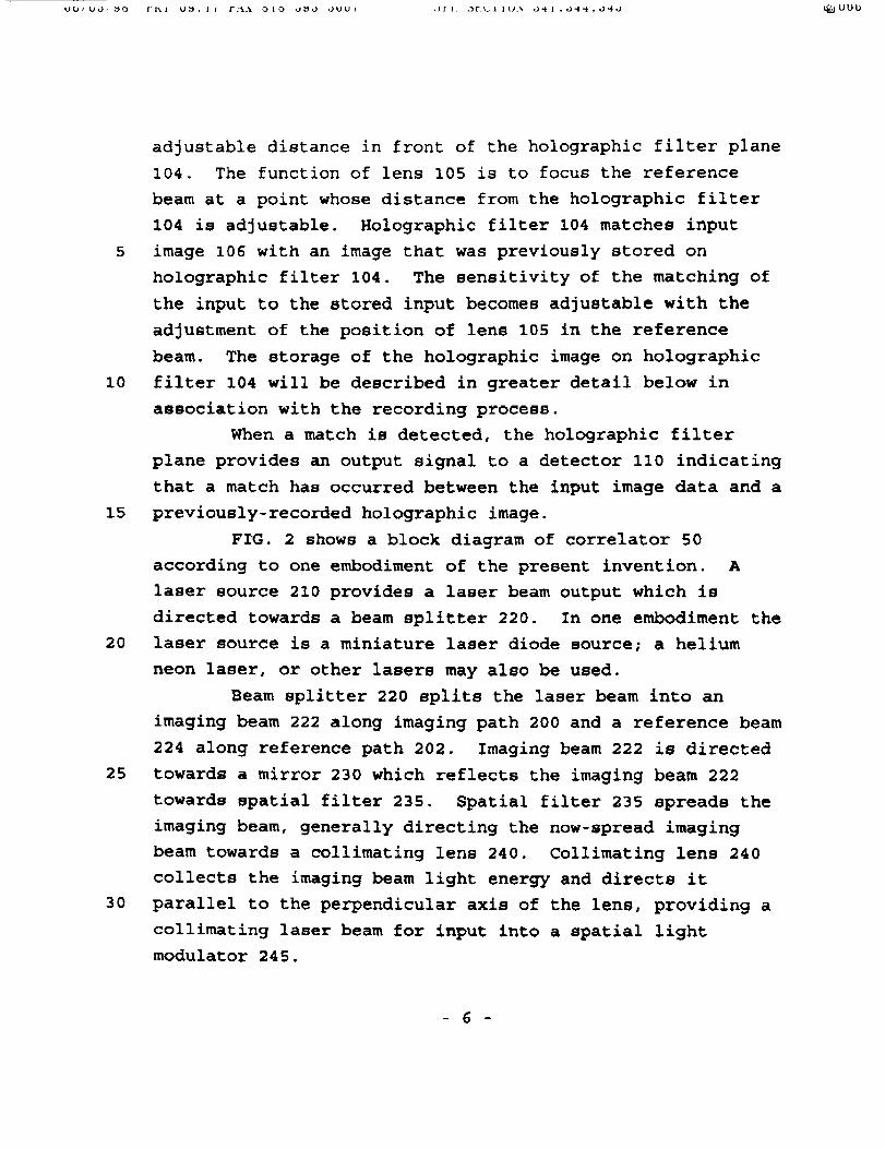
FIG. 1 shows a block diagram of a laser opto-
electronic correlator 50 including a laser i00 for providing
a laser beam output to a spatial light modulator 102 and
holographic filter 104. The laser beam input to spatial
light modulator 102 acts as a carrier for an input image 106
which is provided as an input to the spatial light modulator
102. A carrier beam output 108, including the image
information associated with input image 106, forms an input
to holographic filter 104. The image-carrying laser beam
through spatial light modulator 102 is Fourier transformed
spatially by Fourier lens 103 which is placed at a distance
of one focal length in front of the holographic filter plane
104. Holographic filter 104 also receives a reference beam
from laser source I00 as an input thereof. The reference
beam passes through a lens 105 which is placed at an
- 5 -
10
15
2O
25
3O
adjustable distance in front of the holographic filter plane
104. The function of lens 105 is to focus the reference
beam at a point whose distance from the holographic filter
104 is adjustable. Holographic filter 104 matches input
image 106 with an image that was previously stored on
holographic filter 104. The sensitivity of the matching of
the input to the stored input becomes adjustable with the
adjustment of the position of lens 105 in the reference
beam. The storage of the holographic image on holographic
filter 104 will be described in greater detail below in
association with the recording process.
When a match is detected, the holographic filter
plane provides an output signal to a detector ii0 indicating
that a match has occurred between the input image data and a
previously-recorded holographic image.
F_G. 2 shows a block diagram of correlator 50
according to one embodiment of the present invention. A
laser source 210 provides a laser beam output which is
directed towards a beam splitter 220. In one embodiment the
laser source is a miniature laser diode source; a helium
neon laser, or other lasers may also be used.
Beam splitter 220 splits the laser beam into an
imaging beam 222 along imaging path 200 and a reference beam
224 along reference path 202. Imaging beam 222 is directed
towards a mirror 230 which reflects the imaging beam 222
towards spatial filter 235. Spatial filter 235 spreads the
imaging beam, generally directing the now-spread imaging
beam towards a collimating lens 240. Collimating lens 240
collects the imaging beam light energy and directs it
parallel to the perpendicular axis of the lens, providing a
collimating laser beam for input into a spatial light
modulator 245.
- 6 -
10
15
20
25
30
In one embodiment, spatial light modulator 245 is a
90 ° prism. The 90 ° prism is oriented such that the
collimated laser beam output from collimating lens 240 is
provided as an input onto a first side 246 of the prism.
The prism includes an imaging surface 247 for receiving an
image for recording or comparison operations. The imaging
surface 247 is on the long hypotenuse side of the prism
opposite the 90 ° angle.
The imaging data, e.g. a fingerprint is acquired on
imaging surface 247 which may include a finger box (not
shown) for maintaining the relative position of a finger
relative to the imaging surface.
A second side 248 of the prism adjacent to first
side 246 provides a carrier beam output 249, combining the
image data received at imaging surface 247 with the
collimated laser beam output from collimating lens 240
received at first side 246. The prism realizes the real-
time input of an image via the total internal reflection
mechanism of the prism device. Specifically, the collimated
laser beam input from the collimating lens 240 acts as a
carrier for the image data, thereby providing a carrier beam
output which is directed towards a transform lens 250.
As was described above, spatial light modulator 245
provides an output carrier beam 249 as an input to transform
lens 250 having a focal length of D1. Transform lens 250
may be a Fourier transform lens which provides a spatial
Fourier transform of the image data which is focused on a
matched spatial filter (MSF) plane, generally indicated at
260, A cross section of a focal point of the output from
transform lens 250 includes complex structures associated
with the input image provided as an input to spatial light
modulator 245.
- 7 -
10
15
2O
25
3O
Film 265 is placed at MSF plane 260 and is exposed
to the focused carrier beam via an electronically controlled
shutter (not shown) associated with the MSF plane. The
electronically controlled shutter controls the exposure of
film 265 to light from the imaging optical path.
Referring now to the reference path, beam splitter
220 provides a reference beam 224 which is directed toward a
mirrors 232 and 234 for reflection towards the MSF plane
260. Specifically, after reflection from mirror 234, the
reference beam passes through a spatial filter 236 which
spreads the output beam. The light energy is there after
collected by a second transform lens 238 which focuses the
reference beam toward a detector 270. In one embodiment,
the transform lens is a Fourier transform lens. The
reference beam is aligned such that the light energy
directed from the transform lens 238 passes through MSF
plane 260 prior to being focused at detector 270. In one
aspect of the present invention, the position of the
transform lens 238 is adjustable in its optical axis such
that the sensitivity of detection may be adjusted.
The Recordinu Process
In order to record an image for comparison at a
future time, an image recording process is invoked. The
image recording process consists of providing an image, such
as a fingerprint, at the imaging plane of spatial light
modulator 245. During the recording process, the laser
source 210 outputs a laser beam which is split by beam
splitter 220 into an imaging beam 222 and reference beam
224. In the imaging optical path, the imaging beam is
collimated through collimating lens 240 to provide a
collimated laser beam output to spatial light modulator
(prism) 245. Spatial light modulator 245 enhances the
_
i0
15
2O
imaging beam and also receives as an input the fingerprint
that is to be recorded at imaging plane 247.
The collimated laser beam output from collimating
lens 240 acts as a carrier for the fingerprint image
providing a carrier beam as an output from spatial light
modulator 245 for transfer to transform lens 245. The focal
point for transform lens 245 is at MSF plane 260.
At the same time, the laser source 210 provides a
reference beam in the reference optical path which is
reflected through a second transform lens 238 whose output
is directed toward and interferes with the carrier beam at
MSF plane 260. In one embodiment, the second transform lens
is identical to the first transform lens. Second transform
lens 238 may be a Fourier transform lens. The second
transform lens is configured to focus the reference beam a
predetermined distance D2 beyond the MSF plane. Film 265
placed at MSF plane 260 is exposed tO the interference
pattern created by the complex structure associated with the
input image (fingerprint) in the carrier beam and the
reference beam by the electronic controlled shutter
associated with MSF plane 260. Thereafter the film is
developed and replaced at the MSF plane for use in the
reconstruction process.
25
3o
Reconstruction/Recoqnition_Process
FIG. 3 shows the reconstruction process. Laser
source 210 provides a laser beam which is directed through a
pinhole spatial filter 235 toward a collimating lens 240.
Alternatively, the same set-up as described in the recording
process may be used including a beam splitter. However, the
reference optical path is not utilized in the reconstruction
process. Collimating lens 240 provides a collimated laser
beam output for input into spatial light modulator 245. A
- 9 -

5
I0
15
2O
fingerprint seeking to be verified (recognized) is provided
as an input to imaging plane 247 of spatial light modulator
(prism) 245. Spatial light modulator 245 receives the input
image and utilizes the collimating laser beam as a carrier
to carry image data to the transform lens 250. Transform
lens 250 focuses the image data to a focal point in MSF
plane 260.
The electronically controlled shutter associated
with MSF plane 260 is opened to expose the film to the
focused carrier beam. In the absence of the interfering
reference beam, the exposed and developed film acts as a
filter to the imaging optical path, performing a matching
function associated with a previously recorded image.
Specifically, film 265, upon being exposed to the complex
structure in the focal point of the carrier beam (after
being developed), defracts light toward detector 270 as if
the reference beam were present if the fingerprint data in
the carrier beam is the same as the previously recorded
fingerprint data. In the event a match occurs, detector 270
receives a light pattern which is indicative of a match
condition.
25
3O
Relationship between Recognition Sensitivity and the Lateral
and Lonaitudinal displacement of the Filter and Inp_ Image
Repeatability of matching capability in correlator
50 is a primary concern for commercial applications. In
order to assure repeatability, the MSF plane (film 265)
should be located exactly at the focal point of transform
lens 250 when replaced in the correlator after developing.
Longitudinal and lateral displacements of the MSF plane may
result in poor repeatability characteristics for other
existing devices. One aspect of the present invention
provides a solution for the enhancement of repeatability of
- I0 -
recognition. An analysis of the effects of longitudinal and
lateral displacement of the filter (film 265) indicated that
the effect of longitudinal displacement on repeatability was
much less than that of lateral displacement. However,
5 either may skew results. The inventors prefer the following
technique for replacing film 265 at the focal point for the
transform lens 250 by examining a correlation peak.
During the recording process, the focal point (at
MSF plane 260) associated with the transform lens 250 is
i0 located thereby defining MSF plane 260. Film 265 is fixed
at this location before recording. After removal and
development of film 265, film 265 is replaced in
approximately its original location. The original image is
applied to the spatial light modulator or through the prism.
15 A correlation peak is detected associated with the maximum
intensity of light received at detector 270 when moving film
265 only laterally. This is accomplished by a manual review
or by an automated vision process. The film can be returned
to roughly its original position moving the filter
20 continuously in a lateral direction while observing the
correlation peak intensity received by the detector centered
at the focal point of the reference beam. Film 265 is
thereafter moved until the intensity reaches its maximum at
the detector. After repeated experiments with the system
25 using the above-described approach, it has been found that
the translation sensitivity is dependent on the ratio D2/D _
of the system configuration. This will be elaborated
further below.
In addition, shifts in the fingerprint image either
30 laterally or longitudinally will effect the repeatability of
the correlator system. Specifically, lateral and
longitudinal shifts in the input image will result in shifts
in the correlation peak. In order to minimize the
- ii -

5
I0
15
repositioning error for objects, various control mechanisms
may be utilized including a confining box.
In making the correlator system compact, a small
area detector instead of a detector array may be utilized.
The small area detector includes a small pinhole as a
receiving aperture. The size of the pinhole is configured
to be large enough to detect the correlation peak while able
to tolerate a certain amount of input displacement. In
addition, the size of the pinhole should be small enough to
reject most of the background noise. In one embodiment, for
the identification of fingerprints (where the fundamental
spatial frequency of two line pairs per millimeter occurs),
the width of the correlation peak is approximately 0.5
millimeters for the case where the D2/D1 equals i. In this
embodiment, the diameter of the pinhole is approximately 1
millimeter.
2O
25
3o
Adjustment of the Translation Sensitivity via the AdjustmeDt
of Geometric Parameters DI and D_
In an embodiment which utilizes a pinhole detector,
the movement of the correlation peak due to laterally
shifted input images must be compensated for. As indicated
above, the correlation peak will move laterally with a
laterally shifted input image. Accordingly, as the
correlation peak moves laterally (tracking the movement of
the input image), the amount of light received at the
detector is diminished. This diminishment of light at the
detector due to a shifted input image is generally referred
to as translation sensitivity.
Translation sensitivity is a performance parameter
which relates to the ability of the correlator to detect a
match, given a displacement of the input image. Given the
movement of the correlation peak due to a shifted input
- 12 -
OI'L blLLiIU_ O@I,L)@@.O@O _UiO
image, it would not be convenient to adjust the pinhole
position each time to match the input displacement.
However, analysis has shown that translation sensitivity for
the correlator system of the present invention is strongly
5 dependent on the geometric configuration of the system,
namely the relationship of the parameters D2 and DI.
Translation sensitivity can be reduced by decreasing the
ratio of D2 to DI, resulting in an increase in the overall
repeatability of the correlator. Accordingly, the ability
i0 to adjust the translation sensitivity of the optical
correlator via the adjustment of the ratio between D2 and D1
results in improved image recognition capability of the
system.
FIG. 4 shows a diagram of lateral displacement of
15 input image (such as a fingerprint) relative to the
intensity of the correlation peak. Ratios of D2 to D1 of
less than approximately 1 will yield decreased translation
sensitivity. In one embodiment, the ratio is 1 to 4, or .25
The smaller the D2 to D1 ratio, the more tolerant the system
20 is to lateral displacements
25
30
ComDensation for Zero Spatial Freguencv Term of Image-
Another problem effecting the final correlation
results is the zero spatial frequency (DC) term of the
carrier beam, whose relative value is greater than 0.5 in
the practical prism input case. The correlation between
D.C. terms of two different images may introduce a
significant background peak intensity. A simple approach to
eliminate this effect is to overexpose film 265 in the MSF
plane during the recording step, so that the DC portion of
the center of the spectrum becomes entirely dark and hence
has no diffraction function.
- 13 -

5
10
15
Detection of partially Obscured Images
At the detector the relevant intensity of the light
detected from a match or a non-match condition can be
described as follows. Assuming that a perfect match
provides a relative intensity of 1.0, the system of the
present invention typically returns (detracts) approximately
0.35 or 35% of the light in a no-match condition. For the
case of no-input image (background test), approximately 18%
of the imaging light is defracted through the MSF filter
plane. Accordingly, the present invention may be utilized
to recognize partially obscured images by setting a
threshold for detection to be between the ideal relative
intensity of 1.0 and the no-match return level of
approximately 35%. In one embodiment, the match threshold
is set at approximately between 50% and 90%, with 60%
preferred. At these levels, partially obscured objects
which otherwise may not have been detectable by other
recognition systems may be identified.
2O
25
3O
Alternative Embodiments
In one embodiment, transform lens 238 and 250 may be
multi-channel lens. Electronic shutter associated with MSF
plane 260 is used to expose a plurality of locations on film
265. Multi-channel lens create a plurality of focal points
at MSF plane 260, each focal point including complex image
information associated with the image input at the spatial
light modulator. The electronic shutter is used to expose
film 265 to only one of the focal points, storing the
information at a predetermined position on film 265.
Accordingly, a plurality of image interference patterns may
be stored on the same film 265. During reconstruction,
electronic shutter sequences through the various stored
images to detect a match. Alternatively, the electronic
- 14 -

shutter may be opened completely exposing all of the stored
interference patterns. A match is detected based on the
defracted light received at the detector just as described
above.
The present invention has been described in terms of
one or more embodiments. The invention, however, is not
limited to the embodiments depicted or described. Rather,
the scope of the invention is defined by the claims which
follow.
- 15 -
1
23
4
5
6
7
8
9
i0
ii
12
13
14
15
16
17
What is claimed is:
i. An apparatus for recording images comprising:
a laser source producing a laser beam;
a spatial light modulator receiving an image for
recording and said laser beam, said laser beam acting as a
carrier for said image, said spatial light modulator
outputting a carrier beam including image data;
a first transform lens receiving said carrier beam,
said first transform lens having a predetermined focal
length D1 focusing said carrier beam at a first plane;
an adjustable transform lens for receiving said
laser beam and outputting a focused reference beam directed
toward and interfering with said carrier beam at said first
plane, said focused reference beam having a focal point an
adjustable distance D2 beyond said first plane; and
a film located at said first plane for recording an
interference pattern between said focused reference beam and
said carrier beam.
1
2
3
4
2. The apparatus of claim 1 wherein said transform lens
and said adjustable transform lens are multi channel lens,
and where said electronic shutter exposes said film to a
single channel of data at a time.
3. The apparatus of claim I where a ratio of D2 to D1
is approximately 50 to 90 percent.
4. The apparatus of claim 1 where a ratio of D2 to D1
is approximately 60 percent.
5. The apparatus of claim 1 where said detector is a
detector array.
- 16 -
6. The apparatus of claim 1 where said detector is a
pin hole detector.
7. The apparatus of claim 1 where said spatial light
modulator is a 90 ° prism.
8. The apparatus of claim 1 wherein said laser source
is a helium neon laser.
1
2
3
4
5
6
7
8
9
i0
ii
12
13
14
15
16
9. An apparatus for reconstructing images comprising:
a laser source providing as an output a laser beam;
a spatial light modulator receiving as an input an
image for processing and said laser beam, said laser beam
acting as a carrier for said image, said spatial light
modulator outputting a carrier beam including image data;
a transform lens receiving said carrier beam, said
transform iens having a predetermined focal length focusing
said carrier beam at a first plane;
a film located at said first plane including a
recorded interference pattern associated with an image; and
a detector located a predetermined distance from
said first plane for receiving light refracted from said
film, such that light is refracted and focused at said
detector if said image matches said recorded interference
pattern.
1
2
3
4
5
6
i0. An apparatus for recording images comprising:
a laser source providing as an output a laser beam;
a beam splitter receiving said laser beam and
splitting it into an imaging beam and a reference beam;
a collimating lens for receiving said imaging beam
and providing as an output a collimated laser beam;
- 17 -

,IKI. _t_k. | LU', 04I,d44,d4O _. OlO
7
8
9
10
11
12
13
14
15
16
17
18
19
20
21
22
23
24
25
26
a spatial light modulator receiving as inputs an
image for recording and said collimated laser beam, said
collimated laser beam acting as a carrier for said image,
said spatial light modulator outputting a carrier beam
including image data;
a transform lens receiving said carrier beam, said
transform lens having a predetermined focal length D1
focusing said carrier beam at a first plane;
a shutter array between said transform lens and said
first plane, said shutter array including an open position,
a closed position and means for switching between the two;
an adjustable transform lens for receiving said
reference beam and outputting a focused reference beam
directed toward and interfering with said carrier beam at
said first plane, said focused reference beam having a focal
point an adjustable distance D2 beyond said first plane; and
a film located at said first plane and exposed when
said shutter array is in said open position for recording an
interference pattern between said focused reference beam and
said carrier beam.
1
2
3
4
5
6
7
8
9
10
11
11. An apparatus for reconstructing images comprising:
a laser source providing as an output a laser beam;
a beam splitter receiving said laser beam and
splitting it into a imaging beam and a reference beam;
a collimating lens for receiving said imaging beam
and providing as an output a collimated laser beam;
a spatial light modulator receiving as an input an
image for processing and said collimated laser beam, said
collimated laser beam acting as a carrier for said image,
said spatial light modulator outputting a carrier beam
including image data;
- 18 -

L_..9U J _
12
13
14
15
16
17
18
19
20
21
22
23
24
25
1
2
3
4
5
6
7
8
9
10
11
12
13
14
15
16
17
a transform lens receiving said carrier beam, said
transform lens having a predetermined focal length focusing
said carrier beam at a first plane;
a shutter array between said first transform lens
and said first plane, said shutter array including an open
position, a closed position and means for switching between
the two;
a film located at said first plane including a
recorded interference pattern associated with an image; and
a detector located at a predetermined distance from
said first plane for receiving light refracted from said
film when said shutter array is in said open position, such
that light is refracted and focused at said detector if said
image matches said recorded interference pattern.
12.
of :
A method for recording an image comprising the steps
providing a laser beam;
splitting said laser beam into an imaging beam and a
reference beam;
superimposing an image on said laser beam resulting
in a carrier beam;
focusing said carrier beam by a transform lens at a
first plane;
focusing said reference beam by an adjustable
transform lens and outputting a focused reference beam
directed toward and interfering with said carrier beam at
said first plane, said focused reference beam having a focal
point an adjustable distance beyond said first plane; and
recording an interference pattern between said
focused reference beam and said carrier beam at said first
plane.
- 19 -
1
2
3
4
5
6
7
8
9
I0
Ii
12
13
14
15
13.
of:
A method of verifying an image comprising the steps
providing a laser beam;
superimposing an image to be verified on said laser
beam resulting in a carrier beam;
focusing said carrier beam through a transform lens
at a first plane;
providing a recorded interference pattern associated
with at least one image at said first plane, said recorded
interference pattern refracting light from said at least one
image to a detecting plane; and
detecting a match between said image and said
recorded interference pattern based upon an amount of light
refracted through said recorded interference pattern located
at said first plane and received at said detecting plane.
1 14. A method for recording and reconstructing an image
2 comprising the steps of:
3 providing a laser beam;
4 splitting said laser beam into an imaging beam and a
5 reference beam;
6 collimating said imaging beam resulting in a
7 collimated laser beam;
8 superimposing an image on said collimated laser beam
9 resulting in a carrier beam;
10 focusing said carrier beam by a transform lens at a
11 first plane;
12 focusing said reference beam by an adjustable
13 transform lens and outputting a focused reference beam
14 directed toward and interfering with said carrier beam at
15 said first plane, said focused reference beam having a focal
16 point an adjustable distance beyond said first plane;
- 20 -
17
18
19
20
21
22
23
24
recording an interference pattern between said
focused reference beam and said carrier beam at said first
plane; and
detecting a match between a previously stored
interference pattern and a subsequent image by detecting
light refracted and focused through said recorded
interference pattern at a detection plane a predetermined
distance from said first plane.
- 21 -

•.ILL .')L._IIU._, 04_.O't_._'fO I-_lt1¢,¢.
PATENT
ATTOP.NEY _CKET _: 068161042001
TRANSLATION SENSITIVE .ADJUSTABLE COMPACT OPTICAL CORR_I__TOR
_bs_ract of the Disclosure
5 A sensitivity adjustable compact opto-electronic
correlator and pattern recognition system for identification
of a partially obscured or modified objects includes a laser
source, a spatial light modulator, a transform lens, a
holographic matched filter, and a detector located at a
I0 classification output plane. The laser source outputs a
laser beam in an imaging optical path and a reference
optical path for use during a recording process. The
imaging optical path directs the laser beam output through a
spatial light modulator for entering an input image that is
15 to be identified. The laser beam acts as a carrier for the
input image which then passes through a transform lens
having a focal length D1 at a first (holographic) plane. A
complex structure associated with the input image is located
within the cross-section of the focal point at the first
20 plane. The reference optical path includes a reference beam
which is reflected through an adjustable transform lens
whose output is directed toward and interferes with the
carrier beam at the first plane. The adjustable transform
lens is configured such that the reference beam is focused
25 an adjustable distance D2 beyond the first plane. A film is
placed at the holographic plane to record the interference
pattern generated by the interference of the imaging optical
path and the reference optical path. Thereafter, the film
may be developed and acts as a holographic matched filter
30 when replaced back at the holographic plane for use in
recognizing an associated object or image.
39225.Pll
- 22 -

t
m
15"
T"
t I ,
(>
)
? \
1
1_,r--_-!
f_
I r,
t...- ...........

0
/
Q
/,-_J
m

m0

[
-r-
Q
0
o
Rslatlvt intensityof the Correlatl0n Pesk
o p p p_t dk 41, I_" "

A Large-Capacity Holographic Associative Memory System
Hua-Kuang LiuDepartment of Electrical Engineering
University of South AlabamaMobile, Alabama 36688-0002
Yahong JinDepartment of Electrical and Computer Engineering
University of California at Santa BarbaraSanta Barbara, CA 93106
and
Neville I. Marzwell
Jet Propulsion LaboratoryCalifornia Institute of TechnologyPasadena, California 91109-8099
Abstract: The concept of a multi-stage holographic optical random-access memory (HORAM) system is described. The multi-stageHORAM can be used for high-capacity storage and high-speed random retrieval of information. The input to the system may be of theform of pairs of images that are arranged in such a way that joint Fourier transforms can be recorded at the output plane which has alarge array of different joint transforms. Associative memory and retrieval can be made based on the principle of inner-product neuralnet. The spatial multiplexed, instead of angular multiplexed, architecture allows parallel information retrieval without any moving part.A two-stage HORAM, using a Dammann grating and a multi-focus holographic lens, capable of storing 2000 holographic matchedfilters of input images is used to demonstrate the feasibility of the technique. The multi-stage technique can also be applied to many-to-many free-space interconnections with capability greater than that of a single-stage method. This randomly adaptive and dynamicintercormection technique is useful for a variety of optical neural computing and pattern recognition applications.
I. Introduction
In information management and analysis, parameterssuch as communication delays, limited resources, andinaccessibility of human manipulation require moreintelligent, compact, low-power, and light-weightinformation management and data storage techniques L:.Among the various new and innovative techniques being
developed, 3-D volume holographic memory has beenconsidered important and promising for data storage TM. Inthis letter, we report, for the first time, a multi-stage
holographic optical random-access memory (HORAM)system. The multi-stage HORAM can be used for high-capacity storage and high-speed random retrieval ofinformation suitable for a variety of neural computation
and pattern recognition applications. The input to thesystem may be of the form of pairs of images that arearranged in such a way that joint Fourier transforms canbe recorded at the output plane which has a large array ofdifferent joint transforms. Associative memory andretrieval can be made based on the principle of inner-product neural net. The multi-stage HORAM has muchgreater storage capacity than that of a single-stage multi-channel optical holographic memory and patternrecognition system _214.
An invited paper of the International Symposium on AdvancedLaser and Optoelectronics, Lushan, Jiangxi, China28-31 July, 1998
2. Theoretical Discussion
A block diagram illustrating the concept of a HORAM isshown in Figure 1. The input object information O(x,y) is
presented in a two-dimensional image or data formatwhich is illuminated by a collimated laser beam. The
input O(x,y) can either be presented with a phototransparency or in real-time by a spatial light modulator,such as a liquid crystal television spatial light modulator(LCTV SLM) _s. The input is then passed through a
number of cascaded stages of holographic opticalelements (HOE) and shutter arrays that are represented bythe H blocks. For illustration, a two-stage system with
blocks H 1 and H 2 is used as an example. The HOE in H l
replicates O(x,y) into an array of h I oh I identical O(x,y)'s.
The shutter array in H 1 may be electronically controlled
such that it can let any number of the h l'hl replica of
O(x,y) pass through and stop the others. A multi-focusholographic lens _6with h2°h2 foci may be used for the
subsequent H 2 block. A second shutter array may be used
to select one of the foci of the multi-focus lens. In the
recording of the matched filter at plane F, which is the
output of the block H 2, (hl.h2) 2 Fourier transforms of
O(x,y) will be selected one at a time by the opening ofone of each of the switches of the two shutter arrays.
Meanwhile, a reference beam is applied to interfere withthe Fourier transform for the recording of the holographic
76

matchedfilter.By usingeachFouriertransformin thearraytorecordoneof theimagesor2-Ddata,acompletearrayof matchedfilterscanberecorded.Forexample,ifhl=9 andh2=5,(9°5)2= 2,025FouriertransformsofO(x,y)canbestoredatplaneF.If h1=33andh2=7,andasinglematchedfilterateachfocusisrecorded,atotalof53,361Fouriertransformsof O(x,y)canbestoredatplaneF.ByrandomlyswitchingtheshutterineachoftheH blockto letonlyonechannelof thereferencebeampass,theinputimagesor 2-Ddatabecomerandomlyaccessible.Moredetailsof theH blocksaredescribedbelow.
Information
Input O(x,y)
I.a_r Beam
FouderTransforr_ _
ii
= ° I
Micro-processorControl Center
Figure 1. A concept diagram of a HORAM.
The transmission of the Dammann grating '7',s for theblock H 1 can be described by
t(x,y)= comb Y *g(x,y) a(x,y) (1)' Aa J '
where comb(x,y) represents a comb function", the symbol
* indicates convolution, Ad is the period of the grating,
g(x,y) is the shape of the individual groove of the grating,and a(x,y) is the aperture which in general is the incidentGaussian profile of the laser beam. However, forsimplicity, the aperture is assumed to be open so thata(x,y)=l. The Fourier transform of the grating thenbecomes
T(fx, fy) = A_ [comb(Aaf.,Aafy )]. G(f., f_,)
m _ n=._E - a<:,:,,)(2)
where 8(fx,fy) is a delta function", and G(fx, fy) is the
Fourier transform of g(x,y). G(f x, fy) acts as a window
function to attenuate those peaks of
- that not wanted,ra=_n=-.-** A d
for a (2M+ I)°(2M+ 1) array, we may design the grating insuch a manner that ideally
Iml,l,,l<-MIml,l,,l>M
(3)
With Eq. (3), Eq. (2) can be expressed as
M Mm n
r<:,:,)-.._,.._,Z (4)
A traditional single-lens Dammann grating Fouriertransform system is shown in Figure 2.
= ; I___---I f I
Figure2. Diffraction of light passing through aDammann grating and a lens.
A multi-focus hololens t6 with its architecture and
functionality as shown in Figure 3 may be used as theHOE in the block H2. The multi-focus hololens can be
used to produce an array of Fourier transforms of thesame input image. When the input is an image carded bya collimated laser beam, the multi-focus hololens will
produce at its focal plane an array of replicated Fouriertransforms of the input. When one of the foci passes
through a selection array spatial filter, it may be reimagedat the output plane.
I_ .. ,._I Plane with Output/ _J_._ Multi-Focus Selection Array
HOECollimated /- Input
Laser Beam SLM
Figure 3. The architecture and functionality of the multi-focus hololens.
Figure 4 shows an experimental diagram of a two-stageHORAM as described above. A laser beam from an
Argon ion laser is divided into an object beam and areference beam by a beam splitter. The object beam iscollimated by a spatial filter and lens LI combination.
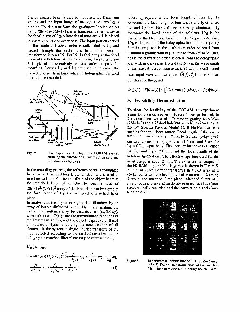
ThecollimatedbeamisusedtoilluminatetheDammanngratingandtheinputimageof anobject.A lensL2 isusedto Fouriertransformthegrating-multipliedobjectintoa(2M+l).(2M+I)Fouriertransformpatternarrayatthefocalplaneof L2,wheretheshutterarray1isplacedtoselectivelyletoneorderpass.Theinputpatterncarriedby thesinglediffractionorderis collimatedbyL3 andpassedthroughthe multi-focuslens.It is Fourier-transformedintoa(2N+I).(2N+I)fociarrayatthefocalplaneofthehololens.At thefocalplane,theshutterarray2 is placedto selectivelylet oneorderto passforrecording.LensesL4 andL5 areusedto re-imagethepassedFouriertransformwherea holographicmatchedfiltercanberecorded.
_-_,¢1_ s Selection
/\ _, /J _ L4 Shutter Array 2
H°l°gr/ap'hicX_/_--1_ L
Matched Filter _ _'V'--_,_ L 3
Filter X \ t _"_ II II I "%,
d l t _._M •-' i.;,;....... I /
laser Beam -- Spatial V lit _ I fFilter Damman _., Selection
Grating uolect Shutter Array I
Figure 4. The experimental setup of a HORAM systemutilizing the cascade of a Dammann Grating anda multi-focus hololens.
In the recording process, the reference beam is collimatedby a spatial filter and lens L combination and is used to
interfere with the Fourier transform of the object beam atthe matched filter plane. One by one, a total of
(2M+l)2.(2N+l) 2 array of the input data can be stored at
the focal plane of L 5, the holographic matched filter
plane.
In analysis, as the object in Figure 4 is illumined by anarray of beams diffracted by the Dammann grating, the
overall transmittance may be described as t(x,y)O(x,y),where t(x,y) and O(x,y) are the transmittance functions of
the Dammann grating and the object respectively. Basedon Fourier analysis '9 involving the consideration of all
elements in the system, a single Fourier transform of theinput selected according to the method described at the
holographic matched filter plane may be represented by
Um (Xm, Ym)
=_jA(tf2)(lf3)(tfh)30( f3 Xm+ f3 m2 l
f3 ym+ f3 n 1 n"l,, (5)
where f2 represents the focal length of lens L 2, f3
represents the focal length of lens L 3, f4 and f5 of lenses
L4 and L 5 are identical and naturally eliminated, fh
represents the focal length of the hololens, I/, d is the
period of the Dammann Grating in the frequency domain,1/. h is the period of the holographic lens in the frequency
domain, (m 1, nl) is the diffraction order selected from
Dammann grating with ml, nl range from -M to M, (m 2,
n2) is the diffraction order selected from the holographic
lens with m2, n2 range from -N to N, • is the wavelength
of the laser, A is a constant associated with the collimated
laser input wave amplitude, and (_)(f_, fy ) is the Fourier
transform of the object
_f_,_ ) = F{O(x, y)} = [.[. O(x, y)exp[-j2_(f_x + f_y)]dxdy.
3. Feasibility Demonstration
To show the feasibility of the HORAM, an experimentusing the diagram shown in Figure 4 was performed. Inthe experiment, we used a Dammann grating with M=4(2M+!=9) and a 25-foci hololens with N=2 (2N+1=5). A25-mW Spectra Physics Model 124B He-Ne laser was
used as the input laser source. Focal length of the lensesused in the system are fl=10 cm, f2=20 cm, f3=f4=f5=38
cm with corresponding apertures of 4 cm, and 5 cm forLI and L2 respectively. The aperture for the SORL lenses
L3, L4, and L 5 is 7.6 cm, and the focal length of the
hololens fh=25.4 cm. The effective aperture used for the
input image is about 2 mm. The experimental output ofthe HORAM at plane F of Figure 4 is shown in Figure 5.A total of 2,025 Fourier transforms in a 2-D array of a45.45 foci array have been obtained in an area of 2 cm by5 cm at the matched filter plane. Matched filters at asingle focus and several randomly selected foci have been
conventionally recorded and the correlation signals havebeen observed.
Figure 5. Experimental demonstration: a 2025-channel(45.45) Fourier transform array at the matchedfilter plane in Figure 4 of a 2-stage optical RAM

4. Conclusion
In conclusion, we have described a new technique of
using multiple stages of free-space interconnectionholographic elements to implement a HORAM. We havedemonstrated the technique with the memory capacity ofover 2000 images. Potentially, tens of thousands of
images can be stored. Micro-processors may be used toobtain fast random access to any data set from thememory. An advantage of this technique is that, unlikethe angular multiplexed storage method, there is no need
of moving any component in the system. High-speedaccess is therefore achievable. Each of the thousands of
Fourier transforms in the array may be used to record amatched filter of an input image of 256.256, 512.512 orany other number of pixels. Therefore, with the HORAM,
ultra-high speed special-purpose computing goals can beachieved. For example, simultaneous optical pattern
recognition and/or data processing of the super-largearray at 1 microsecond means a computing speed on the
order of 1.2-1016 bits/sec assuming that binary images
are used. If the finger prints of criminals are stored in thememory, the HORAM can determine whether an arbitraryinput finger print belongs to one of the criminals. The
recognition can be accomplished remotely and theHORAM can make instantaneous decisions.
The multi-stage architecture can also be applied to many-to-many free-space interconnections with each input pixelreconfigurably connectable to any number of the outputfoci. The interconnection capability should be muchhigher than that of any other single-stage free-space
optical interconnection method reported". This randomly
adaptive and dynamic interconnection technique is usefulfor a variety of optical neural computing and opticalpattern recognition applications.
Soskin, and V. L. Vinetskii, Ferroelectrics, 22,949(1979).
4. J.F. Heanue, M. C. Bashaw, and L. Hesselink,
Science, 265(5173), 749 (1994).
5. F.H. Mok, Opt. Lett., 18, 915 (1993).6. S. Yin, H. Zhou, F. Zhao, M. Wen, Z. Yang, and F.
T. S. Yu, Opt. Comm., 101, 317 (1993).7. P.A. Mitkas and L. L Irakliotis, J. Opt. Memories
Neural Net., 3(2), 87 (1994).
8. J.H. Hong, I. McMichael, T. Y. Chang, W. Christian,
and E. G. Pack, Opt. Eng. 34(8), 2193 (1992).9 D. Psaltis, Byte, 17(9), 179 (1995).
10. J. R. Wullert II and Y. Lu, Appl. Opt., 33(11), 3192(1994).
11. F. T. S. Yu and S. Yin, Optical Memory NeuralNetworks, 3, 207 (1994).
12.D. Gregory, G. Duthie, and H. K. Liu, Appl. Opt., 23,4560-4570 (1984).
13. H. K. Liu, J. Barhen, and N. Farhat, U. S. Patent No
5,544,280, issued on August 6, 199614.H.K. Liu and J. Wu, Appl. Opt., 31, 4631 (1992)
15. H. K. Liu and T. H. Chao, Appl. Opt., 28, 4772(1989).
16.Y.Z. Liang, D. Z. Zhao, and H. K. Liu, Appl. Opt.,22, 3451 (1983).
17. H. Dammann and K. Grotler, Opt. Comm., 3, 312(1971)
18. M. Blume, F. B. McCormick, P. J. Marchand, and S.
C. Esener, Proc. SPIE, 5537, 180 (1995).19. J. W. Goodman, Introduction to Fourier Optics,
McGraw-Hill, (1968).
Acknowledgment
The research work was supported by (I) NASAAdvanced Concepts Research Fellowship Grant No.NAG 2-1050; (2) NASA Contract No. NAS7-1307 withthe Standard International Corporation, Lumin, Inc., theUniversity of South Alabama, and the University ofCalifornia at Santa Barbara; (3) DOE contract DE-AC05-84OR2140 to ORNL and ORNL's Subcontract No. 85X-
ST933V to Lumin, Inc.; and (4) DOE Alabama EPSCoRYoung Investigator subcontract to University of SouthAlabama. Helpful technical discussions with Fred
Aminzadeh, and Jacob Barhen, are hereby acknowledged.
References
1. B.J. Goertzen and P. A. Mitkas, Opt. Eng., 35(7),1847 (1996).
2. P.B. Berra, A. Ghafoor, P. A. Mitkas, S. J.Marcinkowski, and M. Guizani, IEEE Trans.
Knowledge Data Eng., 11, 111 (1989).3. N.V. Kukhtarev, V. B. Markov, S. G. Odulov, M. S.
Advanced ultra-high-capacity optical randomaccess memory and pattern recognitiontechniques
Hua-Kuang Liu, FELLOWSPIEYahong Jin, MEMBERSPIEUniversity of South AlabamaDepartment of Electrical and Computer
EngineeringMobile, Alabama 36688-0002E-mail: [email protected]
Neville I. Marzwell
California Institute of TechnologyJet Propulsion LaboratoryPasadena, California 91109-8099
Abstract. The architecture and mathematical analysis of a new multi-channel multistage holographic optical random access memory(HORAM) architecture and an experimental demonstration of its feasibil-ity are presented. The new HORAM can be used for ultra-high-capacitystorage and high-speed random retrieval of information. A two-stageHORAM, using a Dammann grating and a multifocus holographic lens,clearly shows the capability of storing 2000 holographic matched filters.The functional requirements for key optical elements including lasersources, spatial light modulators, and electro-optical shutters for makinga desired practical and compact HORAM are described. The potentialextension of the HORAM system for multiple-channel optical pattern rec-ognition, classification, and image restoration are described. © 1998so-ciety of Photo.Optica/ Instrumentation Engineers. [S0091-3286(98)02503-3]
Subject terms: random access memory; optical pattern recognition; holographic
lens; Dammann grating; optical pattern classification.
Paper ART-162 received July 2, 1997; revised manuscript received Aug. 19,
1997; accepted for publication Aug. 21, 1997.
1 Introduction
Instruments with high speed and large capacity in situ dataidentification, classification, and storage capabilities are re-quired for information management and analysis. For ex-ample, in National Aeronautics and Space Administration(NASA) applications, extremely large volumes of data setsmust processed in space exploration, space habitation andutilization, and in various missions to planet-earth pro-grams. Parameters such as communication delays, limitedresources, and inaccessibility of human manipulation re-
quire more intelligent, compact, low-power, and light-weight information management and data storagetechniques) '2 For this reason, new and innovative tech-niques are being developed by many researchers in thefield. Among the various techniques being developed, the
3-D volume holographic memory has been considered asone of the most important and promising for datastorage. 3-11 For example, Mok 5 reported that more than
thousands of holograms can be stored in a lithium niobatecrystal via angular multiplexing, Heanue et al. 4 demon-
strated the storage and retrieval of digital data using a vol-ume hologram, and Yu and Yin have used a volume pho-torefractive crystal to make a reflection type matched filterapplicable for pattern recognition, it The purpose of thispaper is to present a new and basic concept of a multichan-nel multistage spatially parallel holographic optical randomaccess memory (HORAM) system and the theoreticalanalysis of a two-stage HORAM architecture. The prelimi-nary experimental results demonstrating the storage planeof a 2000-channel system and its potential for optical pat-tern recognition are presented. We then present various op-tical computing methods based on the HORAM architec-ture. The multistage HORAM can be used for the storage
and random information retrieval among an extremely largeamount of data and a family of pattern recognition applica-tions. Advantages of the HORAM include large data stor-
age capacity and high-speed parallel retrieval without mov-ing parts. For a two-stage HORAM, two orders ofmagnitude of increment of the storage capacity can beachieved as compared with that of the single-staged spatial
multiplexed multichannel optical pattern recognition sys-tem previously reported. _2-_4 The practical limitations ofthe new architecture, primarily due to the availability of
some basic components, are described at the end of thepaper to stimulate further technology innovation and ad-vancement required for this important technique.
2 Theoretical Discussion
The basic concept of the HORAM is shown in Fig. I,
where the input information T is presented in a 2-D imageor data format, which is carried by a collimated laser beam.The input can either be presented with a phototransparencyor in real time by a spatial light modulator. An example ofan inexpensive laboratory type electronically addressedspatial light modulator is the liquid crystal television spatiallight modulator 15 (LCTV SLM). The input T is then ap-
plied through a multiple number of cascaded stages of ho-lographic optical elements (HOEs) and shutter arrays that
are represented by the H blocks. Each H block may containHOEs and shutter arrays. The functions of these elements
are described by using blocks Hi and H 2 as examples. The
HOE in H t replicates input T into an array of h 1×hl iden-
tical T's. The shutter array in HL can be electronically con-trolled such that it can let any one of the (hi) 2 replicas of T
pass through and stop the others. The subsequent H2 block
Opt. Eng. 37(3) 779-788 (March 1998) 0091-3286/98/$10.00 © 1998 Society of Photo-Optical Instrumentation Engineers 779
80

Liu, Jin, and Marzwell: Advanced ultra-high-capacity optical random access memory ..
Fourier
--Micro-processor
Control Center
IFi_sl Dllff_actlonof hlht passlng th]rougha Dar'ormann grating[anda
Fig. 1 Block diagram il]ustrating the concept of a HORAM.
has the function of a multifocus holographic lens with(h2) 2 foci. A second shutter array can be used to select oneof the foci of the multifocus lens. Hence at the output of the
block H 2, (h t× h2) 2 Fourier transforms of T will appear
one at a time at plane F since each time one of the Fouriertransforms is selected, it is accomplished by the opening of
one of each of the switches of the two shutter arrays. If oneapplies a reference beam to interfere with the Fourier trans-form, a holographic filter can be recorded at plane F. By
using each Fourier transform in the array to record one ofthe images or 2-D data, a complete array of matched filters
can be recorded. For example, if two H blocks are used
with h i = 9 and h 2= 5, a minimum of (9 × 5) 2= 2025 Fou-
rier transforms of T can be stored at plane F if only one
Fourier transform is recorded at each point of the array.Since holograms can be superpositioned, if each point isused to record four Fourier transforms by angular multi-plexing, over 10,000 matched filters can be recorded atplane F. If h i = 33 and h2 = 7 and a single matched filter ateach focus is recorded, a total of 53,361 Fourier transforms
of T can be stored at plane F. In the preceding examples, ifthe input data are images of human faces, then over 50,000faces can be memorized in a HORAM. In the pattern rec-ognition process, an input can be used to address all thestored holographic filters and therefore auto- or heterocor-relation signals can be obtained. On the other hand, by
switching the shutter in each of the H blocks to let only onechannel of the reference beam pass, one of the input imagesor 2-D data becomes randomly accessible.
One possible implementation of the HORAM in a two-stage architecture is to use a high-efficiency Dammannphase grating _6'17 with a lens and a shutter for Ht, and a
muhifocus holographic lens Is (hololens) with a shutter for
H 2. The transmission of the Dammann grating can be de-19scribed as
,(x,y)=[comb (_-_d, Za)- *g (x,y)]a(x,y), (t)
where * indicates the convolution operator; La is the periodof grating; g(x,y) is the shape of the individual groove;
and a(x,y) is the aperture, which in general is the incidentGaussian profile of the laser beam. However, for simplicity,the aperture is assumed to be open and uniform, so thata(x,y) = 1. The Fourier transform of the grating 19 is
T(f, ,fy) = L,_[comb (L J, ,Ljy)]G(f._ ,f_.)
= E a - ,-m=--ee /1=-o¢
(2)
where G(f, ,fy) is the Fourier transform of g(x,y), and
G(fx,fy) acts as a window function to attenuate those
peaks of E_,=_=E_=_=&(fx-m/Ld) &(fy-n/La) that are
not wanted. For a (2M+ 1)×(2M+l) array, we designthe grating in such a manner that ideally
1 Iml,lnl Ma(fxJ'y)= 0 ]ml,lnl>M. (3)
With Eq. (3), Eq. (2) can be expressed as
T(.f,.fb= a y,- " a f ,- n (4)m=-M n=_M
A traditional single-lens Dammann grating Fourier trans,"form system is shown in Fig. 2.
A multifocus hololens _8 with its architecture and
tionality as shown in Fig. 3 can be used as the HOE in
OutputMulti-Focus Selection Array . !
HOEput !
Laser Beam SLM !_i
Fig. 3 Architecture and functionality of the multifocus
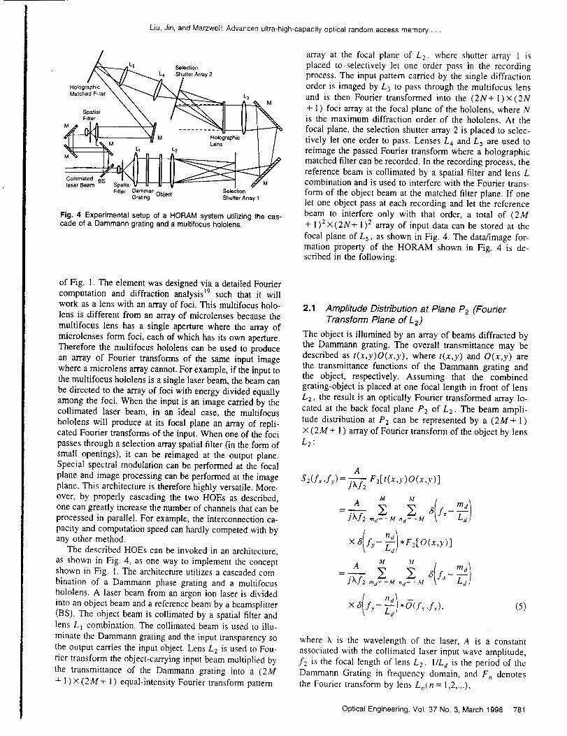
Liu, Jin, and Marzwelk Advanced ultra-high-capacity optical random access memory...
5 Selection
S_j_r Array 2Holographic
Matched Filter L3 M
L1 " L2 Lens
Filter Damman _., Selection
Grating uoject Shutter Array 1
Fig. 4 Experimental setup of a HORAM system utilizing the cas-cade of a Dammann grating and a multifocus hololens.
array at the focal plane of L 2, where shutter array 1 is
placed to-selectively let one order pass in the recordingprocess. The input pattern carried by the single diffractionorder is imaged by L 3 to pass through the multifocus lens
and is then Fourier transformed into the (2N+l)x (2N
+ 1) foci array at the focal plane of the hololens, where Nis the maximum diffraction order of the hololens. At the
focal plane, the selection shutter array 2 is placed to selec-tively let one order to pass. Lenses L 4 and L 5 are used to
reimage the passed Fourier transform where a holographicmatched filter can be recorded. In the recording process, thereference beam is collimated by a spatial filter and lens Lcombination and is used to interfere with the Fourier trans-
form of the object beam at the matched filter plane. If onelet one object pass at each recording and let the referencebeam to interfere only with that order, a total of (2M
+ 1)2×(2N+ 1) 2 array of input data can be stored at the
focal plane of L 5, as shown in Fig. 4. The data/image for-mation property of the HORAM shown in Fig. 4 is de-scribed in the following.
of Fig. 1. The element was designed via a detailed Fouriercomputation and diffraction analysis _9 such that it will
work as a lens with an array of foci. This multifocus holo-
lens is different from an array of microlenses because themultifocus lens has a single aperture where the array of
microlenses form foci, each of which has its own aperture.Therefore the multifocus hololens can be used to produce
an array of Fourier transforms of the same input image
where a microlens array cannot. For example, if the input tothe multifocus hololens is a single laser beam, the beam can
be directed to the array of foci with energy divided equallyamong the foci. When the input is an image carried by thecollimated laser beam, in an ideal case, the multifocus
hololens will produce at its focal plane an array of repli-cated Fourier transforms of the input. When one of the foci
passes through a selection array spatial filter (in the form ofsmall openings), it can be reimaged at the output plane.
Special spectral modulation can be performed at the focal
plane and image processing can be performed at the imageplane. This architecture is therefore highly versatile. More-over, by properly cascading the two HOEs as described,one can greatly increase the number of channels that can be
processed in parallel. For example, the interconnection ca-
pacity and computation speed can hardly competed with byany other method.
The described HOEs can be invoked in an architecture,
as shown in Fig. 4, as one way to implement the conceptshown in Fig. 1. The architecture utilizes a cascaded com-
bination of a Dammann phase grating and a muhifocushololens. A laser beam from an argon ion laser is divided
into an object beam and a reference beam by a beamsplitter(BS). The object beam is collimated by a spatial filter and
lens L_ combination. The collimated beam is used to illu-
minate the Dammann grating and the input transparency so
the output carries the input object. Lens L 2 is used to Fou-
rier transform the object-carrying input beam multiplied by
the transmittance of the Dammann grating into a (2M
+ 1) × (2M + 1) equal-intensity Fourier transform pattern
2.1 Amplitude Distribution at Plane P2 (Fourier
Transform Plane of L 2)
The object is illumined by an array of beams diffracted bythe Dammann grating. The overall transmittance may be
described as t(x,y)O(x,y), where t(x,y) and O(x,y) arethe transmittance functions of the Dammann grating andthe object, respectively. Assuming that the combinedgrating-object is placed at one focal length in front of lens
L2, the result is an optically Fourier transformed array lo-
cated at the back focal plane P2 of L 2 . The beam ampli-
tude distribution at P2 can be represented by a (2M+ 1)
× (2M + 1) array of Fourier transform of the object by lens
L2:
A
S2(f._ ,f y)= _ F2[t(x,y)O(x,y)]
M M
A _ _ _(fm__a)Jhf2 ,nj=-M nd=-_,t
M M
A E E 8(fx -m'l= jhf"-'-2:,.a=-M ,,: -M "-_]
× _5(fy- nc:l 5(.f, ,L,), (5)
where X is the wavelength of the laser, A is a constant
associated with the collimated laser input wave amplitude,f2 is the focal length of lens L 2. IlL d is the period of the
Dammann Grating in frequency domain, and F,, denotes
the Fourier transform by lens L,,(n = 1,2,...),
Optical Engineering, Vol. 37 No. 3, March 1998 781

Liu,Jin,andMarzwell:Advancedultra-high-capacityopticalrandomaccessmemory...
O(fx ,f_)= F2[O(x,Y)]
= f f O(x,y)exp [-j2w(f_+fyy)] _ dy,
(6)
where f_ and fy are the spatial frequencies: fx=x2/(hf2)
and fy = Y2 ](hf2) ; and (x 2 ,Y2) are points in plane P2. Theamplitude distribution at P2 can also be expressed in terms
of the position at plane P2:
x3 Y3 )U3(x3'Y3)=S3 hf3' h'-f3
x 3
(Xf2)(Xf3)
×0 -- -_3 x 3 , -- -_3 y 3 ,(10)
x2 Y2 )U2(x2'Y2)=S2 hf2' h-f2
where
where
A(hf_)2 _ _ _x2--- J(kf2) md=-M na=-M W md
x f2
J(Xf2) h.f2' ,
J_d(f . ,f y)= F3{M a(x,Y)}"
(7)
R.3 Amplitude Distribution at the Fourier Plane ofthe Holographic Lens
The holographic lens Fourier transforms the input
U3(x3 ,Y3) to a (2N+ 1) x (2N+ ] ) array of spectrum ontoits Fourier transform plane. The amplitude distribution is
Md(x2,Y2)=(hf2) 2 Z Z x2-"-_a mdrnd=-M nd=-M
X _(Y2-- _-f2 ,,_). (8)
An aperture can be placed at plane P2 with a selection
filter, which is set to select one of the (2M+1)×(2M
+ i ) equal-intensity diffraction orders.
2.2 Ampftude Distribution at Fourier Plane of Lens
L3
Lens L 3 is placed at distance ./'3 from plane P2. Due to the
input at plane P2, the amplitude distribution at the Fourier
plane of lens L3 can be written as
1
S3(f_2,fy 2) = _ F3[ U2(x2 ,Y2)]
A
(h f2) (h f3) F3{Md(x2'y2)*F2[O(x'Y)]}
A
(_.f2) (h f3 ) F3[Md(X2'Y2)]
× F3F2[O(x,y)]. (9)
The amplitude distribution Eq. (9) can also be expressed interms of the position at Fourier plane of lens L 3 , that is
782 Optical Engineering, Vot. 37 No. 3, March 1998
Sh(f x3,f y3)
N N1
J_.fh mh=-N nh=-N
*Fh[U3(x3 ,Y3)]
A(Xf2) 2
j(hf2)(hf 3)(hfh)
8 fy- nhrrlh=-N nh=-N
f2*Fh['_d( x3 _¢') ]*Fh[O( -f2 _3 Y3) ]_'f3' "J3/J L _ f3 x3'-
A
j(hf2)(hf3)(hfh)
N N !il
mh=-N nh=-N
[_(*FhFa[Md(X 2,y2)]*FhF 3 0 , . (11)
The amplitude distribution [Eq. (11)] can also be ex-pressed in terms of the position at the Fourier plane of theholographic lens, that is
Liu, Jin, and Marzweli: Advanced ultra-high-capacity optical random access memory...
Uh(Xh,Yh)
A(hf3)4(kfh) 2
j(hf2)(Xf3)(Xfh)
X _ _ fi Xh-- mh fimh=-,V nh=-N _ Yh-- _ nh
*M d --_hXh,--_hYh *0 x h,hf2fh
:3)Xf2fh Yh
- f3 Ym),.O( h___h Xm f3' hf2fh
(15)
where (xm ,Ym) is a point at the matched filter plane. It can
be seen that the amplitude distribution at the matched filter
plane is proportional to a (NxN) with (MxM) array of
the Fourier transforms of the object
(ff(fx ,fy) = F[O(x,y)]
= f f O(x,y)exp[-j27r(f_+fyy)] dx dy,
A(hf3) 4
= - j(Xf2)(Xf3)(hfh) Mh(Xh ,Yh)
( f3 f3 ). (_ff( f3• Md -- fh xh '-- fh Yh _'f2fh Xh'
f3 )hfzfh Yh , (12)
where fh is the focal length of the holographic lens, lit h is
the period of the holographic lens in the frequency domain,and
N N( kfh )Mh(Xh,Yh)=(hfh) 2 E E S X h-mh=-N nh=-N W ?nh
× 8( kfhyh- -_h nh). (13)
2.4 Light Amplitude Distribution at the MatchedFilter Plane
For simplicity, L 4 and L5 are selected as a pair of lenseswith the same focal length f4- Lens L 4 is placed at a dis-tance f4 from the Fourier plane of the holographic lens andlens L 5 is placed 2f4 from lens L4. The matched filterplane is at the focal plane of lens L5. The amplitude dis-tribution at the matched filter plane can be expressed as
where
f3 f3
f,= h--'_h Xr,, and f y= _--_h ym .
2.5 Recording of the Holographic Matched Filter
In the recording of the holographic matched filter, two se-lection shutter arrays are placed at the plane P2 and at the
Fourier plane of the holographic lens, respectively. The
shutter arrays are set such that only one order each from the
Dammann grating and the holographic lens is selected to
pass. Once the order (m t ,nl) from Dammann grating and
the order (mE,n2) from holographic lens are selected, the
amplitude distribution at the matched filter plane, or Eq.
(15), becomes
Ura(Xm ,Ym) =hfh
m(hf2)2(hf3)4(hfh)2 8(-x m- m2)J(h f 2)(hf 3)(hf h) W
x ,_ -- y,, -- --_h n2 . 8 x ,_-- --_d m 1
×s(f3 kS2 )\fh Y'- "_d nl
-( f3 f3 y 1]*Ot_ xm' hf2fh
1
Um(xm'Y_)= t./):X:4'_FsF4[Uh(Xh'Yh)]
f4 f4 Ym). (14)---vh(-T, x.,.- T,
Since f4=fs, we have
Um(x_ ,ym) = - Uh(-Xm,-y.,)
A(hf3) 4
= j(Xf2)(Xf3)(hfh)'Mh(--X ....--Ym)or
= -jA(Xf2)(hf3)(Xfh)3fi( --xm----_hkfh m2 )
-Ym---_h f3Ld ml)
× S Ym- f3L""_ nl
- f3
xm, kfz['h(16)
Optical Engineering, Vol. 37 No. 3, March 1998 783

Liu, Jin, and Marzwell: Advanced ultra-high-capacity optical random access memory ...
i!!!!_iii ?!!iiiii? _!!:::::: :
Spatiat Light
Modulator
Input Image
Mulli-Chennel
Collimaled Replicalion
Laser Beam Holographic
Element
Holographic
Matched Filter
Plane Wave Plane with
Reference _ Electronically
Laser Beam _ Controlled
Fourier
Transform
Lens
Fig. 5 Experimental demonstration: a 2025-channel (45× 45) Fou-rier transform array at the plane F in Fig. 1 of a two-stage opticalRAM.
Um(xm,ym)= -JA (k f 2)(kf 3)(kf h)30( h-_ff_h2fl xro
f3 1 f3 f3
,)La nl ' (17)
where m I and n I range from -M to M and m 2 and n2
range from -N to N. Once (ml ,nl) and (m2,n2) are se-lected by shutter arrays 1 and 2, only one Fourier transformof the input image is recorded at matched filter plane. Fromthis analysis, we can see that the total number of channelsof the system is determined by the Dammann grating andthe holographic lens used.
3 Experimental Demonstration
To show the feasibility of the HORAM, a preliminary ex-periment using the configuration shown in Fig. 4 was per-formed. In the experiment, we used a Dammann gratingwith M=4 (2M+ 1=9) and a 25-foci hololens with N
=2(2N+1=5). A 25-mW Spectra Physics Model 164
He-Ne laser was used as the input laser source. Focallength of the lenses used in the system are fl = 10 cm, f2
= 20 cm, and f3 =f4 =f5 = 38 cm with corresponding aper-
tures of 4 and 5 cm for L l and L2 respectively, and 7.62 cm
for the SORL lenses L 3, L 4, and L 5, the focal length of
the hololens fh = 25.4 cm. The effective aperture used for
the input image is about 5 mm. The experimental output ofa two-stage HORAM at the mulplexed Fourier transformarray output plane of Fig. 4 is shown in Fig. 5. A total of
2025 Fourier transforms in a 2-D array of 45×45 fociformat has been obtained in an area of 2×2 cm at the
matched filter plane. Matched filters at a single focus andseveral randomly selected focuses have been recorded andthe correlation signals have been observed.
Spatial Light
Modulator
Input Image
_r] _[ MuftbChannelCollimated Replication
Laser Beem U I HolographicElement
Holographic
Matched F_lter
Plane with
Electronically"
Controlled
Shutter Array
Correlation
Transform V Photo-DetectorLens
(b}
Fig. 6 (a) Multichannel pattern recognition system reording archi-tecture and (b) multichannel pattem recognitionsystemaddressingarchitecture.
4 Optical Pattern Recognition and ComputingMethods Based on the HORAM
The HORAM has a broad range of applications. Based onthe multistage HORAM architecture, a few optical patternrecognition and special-purpose optical computing methodscan be implemented as described next.
4.1 Multichannel Pattern Recognition System
The recording and addressing architecture of a multichan-nel pattern recognition system are shown, respectively, inFigs. 6(a) and 6(b). In Fig. 6(a), the object is presented tothe system via a spatial light modulator illuminated by acollimated laser beam. The image is replicated in a similarmanner as that in the HORAM as described. The replicatedimages form an array of Fourier transform patterns at theholographic matched filter plan where the matched filterscan be made by using a single plane reference wave duringthe image storage process. For each image, a shutter is opento select one of the Fourier transform of the array. In theaddressing process, if an input object image is one of theimages stored, the output correlation signal will immedi-ately reveal the answer. To give a numerical example, if thesame image is rotated five times and stored in the samelocation of a matched filter, an array of 2000 would enable10,000 images to be stored. The capacity of storage wouldallow recognition of images with rotation and scale varia-tions.
4.2 Multichannel Pattern Classification System
The recording and addressing architecture of a mu]tichan-
nel pattern classification system are shown, respectively, in
784 Optical Engineering, Vol. 37 No. 3, March 1998

Liu,Jin,andMarzwell:Advancedultra-high-capacityopticalrandomaccessmemory..
Angular "_
Multiplexable_ "_
Spatial Light Reference "_ _ •
Modulator L_
Input Image
_'_ Multi-ChannelReplication
L.... 8eamJI .=] Holographic
-- - L_ - I Element
Fourier I._
Transform Holographic_
Lens Matched Filter _.Plane with •
Electronically
Controlled
Shutter Array
Table 1 Desired SLM functional requirements.
Functional Features Desired Specifications
Space-bandwidth product 1042× 1042
Aperture dimensions (mm×mm) 5 × 5
Speed (frames/s) 1000
Dynamic range 100:1
Light efficiency 90%Cost $100 or less
fa)
i i Multi-Channel
Collimated Replication
Laser Beam Holographic
- - Element
Spatial Light
Modulator
Input Image
_Class i
I "•_; - M_i_;,_F_,erV"'11csssi
Plane with u
Electronically Classification
Controlled Output Plane
Shutter Array Photo-DetectorArray
(bJ
Fig. 7 (a) Multichannel pattern classification system recording ar-chitecture and (b) multichannel pattern classification system reord-ingarchitecture.
Figs. 7(a) and 7(b). The recording and addressing processesare similar to those described in Sec. 4.1. The major differ-ence is that in this case, an orientation variable plane waveis used for the image storage process. The images or fea-tures belong to the same class is stored with a certain se-
lected orientation of the reference beam. In the addressingprocess, if an input object image is one of the class of theimages stored, the position of the output correlation signalwill immediately reveal the class that the image belongs to.For example, the I0,000 images of the example given inSec. 4.1 can be classified into I00 classes by using 100reference waves each of which is oriented at a distinctive
angle.
4.3 Multichannel Pattern Restoration System
The recording and addressing architecture of a multichan-nel pattern restoration system are shown in Fig. 8. A singleplane wave is used for all the image storage process similar
Holographic
Matched FilterPlane Wave
Plane with
Reference _ ElectronicaityLaser Beam
n _ Controlled RecaIled (i, j)
] Multi-Channel _ Image
Collimated Replication
Laser Bea Holographic
Element
Fourier
Transform (i, j) Shutter Output
Lens Open Imaging
Lens
Fig. 8 Multichannel pattern restoration system addressing architec-ture.
to that of Fig. 6(a). In the image restoration process, the
object beam is shut off and the (i,j)'th stored object imagecan be restored by using the same reference beam and elec-tronically controlled selection shutters placed in front of the
output imaging lens. The image stored at the (i,j)'thmatched filter position will be holographically retrieved bythe recording reference beam. In this case, only one imageat each filter can be stored and recalled. The inverse Fourier
transform is performed by the lens placed after the matchedfilter array. The restored image can be displaced at its focalplane.
5 Discussion
The definition and functional requirements for a traditional
RAM have been realized electronically with impressive ac-complishments and on-going progress in capacity, speed,and compactness. The optical RAM described in this paperis not intended to compete with the digital electronic RAM.The optical RAM architecture can offer an unique featurein high-speed parallel optical pattern recognition over an
extremely large database. However, to achieve the special-purpose computing goals, technological advancement and
breakthroughs in some of the key optical components arerequired. The challenges and opportunities in the researchand development of the components are now briefly dis-cussed.
5.1 Laser Sources
It is desired to have a laser source comparable to a laserdiode in size with a power level comparable to that of anargon ion laser. However, the laser diodes have very poorcoherent length and are not suitable for making holograms.The diode-pumped solid state laser has high power outputbut also lacks of coherence. Hence at the present time it isnecessary to use large-frame lasers as recording sources.
5.2 SLMs for Data Input
The SLM for the input in the optical RAM poses a chal-lenge for device technology development. Many kinds ofSLMs have been developed. These include the Hughes liq-uid crystal light valve, the microchannel plate SLM, themicrodeflection mirror SLM, the ferroelectric liquid crystalSLM, and the liquid crystal television SLM. For high-speedoptical RAM operation, high-frame-rate SLMs with highdynamic range, small size, and large numbers of pixels arerequired. The desired functional requirements for the SLMare listed in Table 1.
No single currently available SLM has all the desired
features, and the price of high-quality SLMs is too high to
Optical Engineering, Vol. 37 No. 3, March 1998 785

Liu, Jin, and Marzwell: Advanced ultra-high-capacity optical random access memory .
use to construct a practical optical RAM. The liquid crystaltelevision SLM is the only inexpensive SLM that meets thelow-cost requirement, but it has other limitations including
speed, contrast, and resolution.
5.3 Optical Lenses and Mirrors
To achieve optimum light utilization efficiency, Fourier op-tical lenses and mirrors must be specifically designed andfabricated. Ideally, a miniaturized optical system with aninput lens of an effective aperture of less than 5 x 5 mmand with other components designed based on this apertureis desired.
5.4 Shutter Arrays
A single-aperture mechanical shutter can be used to writethe input data into the memory. Mechanical shutters havean aperture of 100% transmittance. The position of theshutter can be precisely translated under the control of aPC. An alternative method is to use a liquid crystal shutterarray. These shutters are available mostly in reflectionmode with high distinction ratios. In the addressing mode,the shutters can be completely removed and hence will notaffect the performance of the memory retrieval or patternrecognition functions.
5.5 Holographic Recording Materials
Candidates for real-time holographic recording materialsinclude nonlinear photorefractive crystals, photopolymers,and thermoplastic materials. The recording sensitivity ofthe thermoplastic material is comparable to that of silverhalide film. A simple and compact charging system must bedeveloped for the thermoplastic recording device. More
sensitive photorefractive and photopolymer materials mustbe developed for large-capacity memory.
5.6 Output Detectors
Photodiodes can be used for the detection of a single outputsignal. An array of output signals can be detected by a CCDarray. Large-array position determinable smart pixel de-vices are required for pattern classification applications.
5.7 Light Budget Estimate, Speed, and Applications
Next, we make an estimate of the light budget for a two-stage HORAM based on realizable optical components. As-sume a laser power of 5 W is used. The collimating opticsreduces its power by a factor of 70%, the input SLM re-duces its power by a factor of 90%, the Dammann gratingby 80%, the hololens by 50%, and each of the shutter ar-rays by 50%. Since part of the beam is used by the refer-ence beam, another factor of 90% will be multiplied, mis-cellaneous light loss of the components is represented by afactor of 70%. The overall factor is the multiplication of allthe factors. The resulting factor is about 4%. By dividingthe resulting light power by 2000, a maximum of 100/_Wis available for the recording of a single matched filter. Thesame power level is available for retrieval. If the matchedfilter has a 50% diffraction efficiency, the correlation signalhas an output of at most 50 #W, which is sufficient for thedetection devices. Based on this estimate, the power levelswill reach its limit if we have a 10,000-channel HORAM.
Input Micro*processorObiects Co(_trolCenter
(a)
o.,,oo,...
PartialNoisy Micrmpro_esso_Input ControlCenter
RetrievedNoise-freeOutput
Co)
Fig, 9 Examples of HORAM applications: (a) memory process and
(b) information retrieval.
The retrieval and processing speed is limited by that ofthe input SLM. For a 10,000-channel HORAM, if all theoptimum values of the parameters are used and we assume
that the speed the input SLM is 1000 frames/s with 400
x 600 binary pixels, the processing speed is estimated to be240 Gbits/s. This speed for pattern recognition is valuablefor certain specific applications.
With respect to the applications of these specific opticalcomputing methods, one example of these applications isillustrated in Fig. 9. Figure 9(a) shows how memorizationis accomplished in the HORAM by placing the objects asrepresented by the satellite and space shuttle in the view ofa video camera. Over tens of thousands of 2-D data can be
stored. Microprocessors can be used to control the randomaccess to any data set from the memory. After the HORAMmemorizes all the images presented to it, it becomes smart.When an input such as a partial and noisy space shuttle, asshown in Fig. 9(b), is presented to it, the HORAM canrecover and display at the output screen the perfectly re-trieved image. In addition, the HORAM can be used torecognize an input and tells us whether it belongs to thememory. For example, if the fingerprints of FBI's mostwanted criminals are stored in the memory, the HORAMcan determine whether an arbitrary input fingerprint be-longs to one of the criminals. The recognition can be ac-complished remotely and the HORAM can make a decisionat the speed of light!
6 Conclusions
We have described a new technique of using multiplestages of free-space interconnection holographic elements
786 Optical Engineering, Vol. 37 No, 3, March 1998

Liu, Jin, and Marzwell: Advanced ultra-high-capacity optical random access memory..
to implement a HORAM. We have demonstrated the tech-
nique with a memory capacity of over 2000 images. Poten-
tially, seemingly limited only by the laser power, tens of
thousands of images can be stored. Microprocessors can be
used to control the random access to any data set from the
memory. Each of the thousands of Fourier transforms in the
array can be used to record a matched filter of an input
image. Simultaneous optical pattern recognition and/or data
processing of the superlarge array means a computing
speed of the order of at least 10 _t bitsls. This speed is faster
than those obtainable by any other methods reported. For
example, if the fingerprints of FBI's most wanted criminals
are stored in the memory, the HORAM can determine
whether an arbitrary input fingerprint belongs to one of the
criminals. The recognition can be accomplished remotely
and the HORAM can make the decision at the speed of
light!
Acknowledgments
The research work was performed jointly at the Jet Propul-
sion Laboratory, California Institute of Technology, and the
University of South Alabama. The work was supported by
(l) NASA Advanced Concepts Research Fellowship Grant
No. NAG 2o1050; (2) NASA Contract No. NAS7-1307
with the Standard International Corporation, Lumin, Inc.,
the University of South Alabama, and the University of
California at Santa Barbara; (3) Department of Energy
(DOE) contract DE-AC05-84OR2140 to the Oak Ridge
National Laboratory (ORNL) and ORNL's Subcontract No.
85X-ST933V to Lumin, Inc.; and (4) DOE Alabama EPS-
CoR Young Investigator subcontract to University of South
Alabama. Helpful technical discussions with Fred Aminza-
deh and Jacob Barhen are hereby acknowledged.
References
1. B. J. Goertzen and P. A. Mitkas, "Volume holographic storage forlarge relational databases," Opt. Eng. 35(7), [847-1853 (1996).
2. P. B. Berra, A. Ghafoor, P. A. Mitkas, S. J. Marcinkowski, and M.Guizani, "The impact of optics on data and knowledge base sys-tems," IEEE Trans. Knowl. Data Eng. 11, 111-132 (1989).
3. N. V. Kukhtarev, V. B. Markov, S. G. Odulov, M. S. Soskin, and V.L. Vinetskii, "Holographic storage in electrooptic crystals, I. Steadystate," Ferroelectrics 22, 949-964 (1979).
4. J. F. Heanue, M. C. Bashaw, and L. Hesselink, "Volume holographicstorage and retrieval of digital data," Science 265(5173), 749-752 (1994).
5. F. H. Mok, "'Angle-multiplexed storage of 5000 holograms in lithiumniobate," Opt. Lett. 18, 915-917 (1993).
6. S. Yin, H. Zhou, F. Zhao, M Wen, Z Yang, and F. T. S. Yu, "Wave-length multiplexed holographic storage in a sensitive photorefractlvecrystal using a visible light tunable diode laser," Opt. Commun. 101,317-321 (1993).
7. P. A. Mitkas and L. J. Irakliotis, "Three-dimensional optical storagefor database processing," Z Opt. Mem. Neural Net. 3(2), 87-98 (1994).
8. J. H Hong, I. McMichael, T. Y. Chang, W. Christian, and E. G. Paek,"Volume holographic memory systems: techniques and architec-tures," Opt. Eng. 34(8), 2193-2203 (1995).
9. D. Psahis, "Parallel optical memories," Byte 17(9), 179-182 (1992).10. L R. Wullert It and Y. Lu, "Limits of capacity and density of holo-
graphic storage," Appl. Opt. 33(1 l), 3192-3196 (1994).11. F. T. S. Yu and S. Yin, "Thick volume photorefractive crystal wave-
length-multiplexed reflection-type matched filter," Opt. Mere. Neural,Vet. 3, 207-214 (1994).
12. D. Gregor2,,, G Duthie, and H K. Liu, "Large memory real-timemuhichannel multiplexed pattern recognition," AppL Opt. 23, 4560-4570 (1984).
13. H K. Liu, J. Barhen, and N. Farhat, "Unipolar terminal-attractorbased hemal associative memory with adaptive threshold," U.S.Patent No 5,544,280 (Aug. 1996).
14. H. K. Liu and L Wu, "Optical implementations of terminal-attractor• based associative memory," Appl. Opt. 31 4631-4644 (1992).
15. H. K. Liu and T. H. Chao, "Liquid cr3stal television spatial lightmodulators," AppL Opt. 28, 4772-4780 (1989).
16. H. Dammann and K Grotler, "High-efficiency in-line multiple imag-ing by means of multiple phase holograms," Opt. Commun. 3, 312-315 (1971).
17. M. Blume, F. B. McCormick, P. J. Marchand, and S. C. Esener, "Ar-ray interconnect systems based on lenslets and CGH," Proc. SPIE2537, 180-193 (1995).
18. Y. Z. Liang, D. Z. Zhao, and H. K. Liu, "Multifocus dichromatedgelatin hololens," AppL Opt. 22, 3451-3459 (1983).
19. J. W. Goodman, Introduction to Fourier Optics, McGraw-Hill, NewYork (1968).
Hua-Kuang kiu is a professor of electricalengineering at the University of South Ala-bama (USA) and a Distinguished VisitingScientist at the Center for EngineeringSystems Advanced Research of the OakRidge National Laboratory. Before joiningUSA in September 1995, Dr. Liu was a se-nior research scientist with the Jet Propul-sion Laboratory (JPL), California Instituteof Technology. He received his PhD de-gree in electrical engineering from JohnsHopkins University. Dr. Liu was a profes-
sor of electrical engineering at the University of Alabama from 1969to 1984, has presented many invited talks, seminars, and shortcourses at national and international meetings and universities, andwas a record holder as the three-time recipient of the Best FacultyResearch Award awarded by the Capstone Engineering Society inthe years 1979, 1982, and 1984. In research, Dr. Liu has managedand directed major R&D projects sponsored by National Aeronauticsand Space Administration (NASA), Department of Defense, and De-partment of Energy agencies and industries. He has been a groupleader of advanced optoelectronic computing and information pro-cessing R&D groups at JPL. Dr. Liu's research specialties includeoptoelectronic computing, high-volume data storage and randomaccess memory, information processing, and neural networks. Dur-ing the last decade, Dr. Liu has acquired and managed contractsand projects totaling over $7 million. In new technology develop-ment, he holds over 27 U.S. patents and NASA Awards and Certifi-
cates of Recognition for Technology Innovation. He was recognizedby the Caltech Patent Office as the most prominent inventor in mod-em optics in the history of NASA/JPL Dr. Liu has published morethan 200 technical papers, has participated in many university com-mittees, has organized and chaired over 30 national and interna-tional conferences, and has served as a referee for archival journalsand as a reviewer for major funding agencies. In 1975, Dr. Liufounded a high-tech firm, Lumin Inc., which has made many impor-tant cutting edge technology discoveries. Dr. Liu is a fellow of theOSA and SPIE and is listed in several national and internationalWho's Who publications.
Yahong Jin received her PhD degree inphysics from the Rensselaer PolytechnicInstitute, Troy, New York, and her BS andMS degrees from Shanghai Jiao TongUniversity, Shanghai, China. Since 1995,she has been a visiting assistant professorof electrical engineering at the Universityof South Alabama, Mobile. From 1994 to1995, she was a visiting scientist at theAdvanced Optoelectronic ComputingLaboratory of the Jet Propulsion Labora-
tory, California Institute of Technology, Pasadena, working on opti-cal information processing, pattern recognition, and holography. Hercurrent research interests include optoelectronic computing and ho-lography, ultrafast electromagnetic switching and optical communi-cations, nonlinear crystals, and optical memory and data storage.Dr. Jin has published over 20 refereed journal papers and one bookchapter and has made over 20 presentations at national and inter-national conferences. She is a member of the IEEE, the AmericanPhysical Society, and SPIE
Optical Engineering, Voi. 37 No. 3, March 1998 787

Liu,Jin,andMarzwell:Advancedultra-high-capacityopticalrandomaccessmemory...
NevilleI.Marzwell is project manager foradvanced concepts and technology inno-vation at the Jet Propulsion Laboratory(JPL), Califomia Institute of Technology,Pasadena, and has 25 years experiencein defense and aerospace systems tech-nologies in which he initiated various tech-nology innovations. His area of expertise
:",' is large optical systems for imaging farfainted objects and high energy lasers. He
._dlJ_, has developed adaptive, distributive, andhierarchical control systems for large space structures and has con-tributed developments in autonomous space systems, robotics, and
teleoperated systems. Before joining JPL, he was program managerof advanced technology with the High Energy Laser Research at theRockedyne Division of Rockwell International, where he developedinnovative wavefront sensing and correction systems and opticaland sensor protection systems for surveillance satellites. At Honey-well Research Center he was instrumental in advances in IR detec-tor technology, electro-optical materials, and fiber optical systems.Dr. Marzwell was a Josephine de Karman fellow at the CaliforniaInstitute of Technology and holds a PhD in applied physics andmaterials science from Caltech. He has published 55 papers in ref-ereed and professional journal and has served on various nationaland international panels and workshop, conferences, and sympo-sium committees.
788 Optical Engineering, Vol. 37 No. 3, March 1998