smart office project report
TRANSCRIPT
RFID BASED SMART OFFICE
FYP-07-019
ARSHIAN AHMED K040057 ABDUS SAMAD QURAISHI K040044 ZEESHAN SATTAR K040066 ZAYEEM BIN ALAM K040102
INTERNAL ADVISOR DR. ZUBAIR A. SHAIKH
EXTERNAL ADVISOR
ENGR. ABU ZAFAR ABBASI NATIONAL UNIVERSITY OF COMPUTER AND EMERGING SCIENCES - FAST
JUNE 2008

2
RFID BASED SMART OFFICE
BY
ARSHIAN AHMED K040057 ABDUS SAMAD QURAISHI K040044 ZEESHAN SATTAR K040066 ZAYEEM BIN ALAM K040102
Report submitted in partial fulfilment of the requirements for the degree
of Bachelor of Science in Telecommunication Engineering
DEPARTMENT OF TELECOM AND COMPUTER ENGINEERING
NATIONAL UNIVERSITY OF COMPUTER AND EMERGING SCIENCES - FAST
JUNE 2008

ii
ACKNOWLEDGEMENT
First of all, we are very grateful to Almighty Allah Who gave us opportunity, strength,
determination and wisdom to achieve our goal. Without His support this could not have
been possible.
We would like to acknowledge and extend our heartfelt gratitude to our internal advisor Dr.
Zubair A. Shaikh for his vital encouragement and support. We would also like to thank Mr.
Aqeel-ur-Rehman, who not only served as our supervisor but also encouraged and
challenged us throughout our project. He patiently guided us through the process, never
accepting less than our best efforts.
We are also greatly indebted to our external advisor Mr. Abu Zafar Abbasi for his valuable
suggestions and advices. He always was being there for us despite of his busy schedule.
His comments and suggestion provided the valuable information necessary to complete
the project.
Besides our advisors, we would like to thank our friend Mr. Syed Arsalan Pervaiz (from
computer science dept) for his valuable support in our project software. Last, but not the
least, we thank our parents for giving us life in the first place, for educating us with
aspects from both arts and sciences, for unconditional support and encouragement to
pursue our interests and for all the things they have done for us.
Arshian Ahmed K040057 Abdus Samad Quraishi K040044 Zeeshan Sattar K040066 Zayeem Bin Alam K040102 JUNE 2008

iii
TABLE OF CONTENTS
Page
ACKNOWLEDGEMENT ii
TABLE OF CONTENTS iii
LIST OF TABLES vi
LIST OF FIGURES vii
ABSTRACT ix
CHAPTER 1: INTRODUCTION
1.1 Introduction 1
1.2 Objective 1
1.3 RFID history 2
1.4 Background 3
1.4.1 RFID Tags 3
1.4.2 RFID Reader 3
1.5 Working of RFID 3
1.6 Frequencies of RFID 4
1.7 Future of RFID 4
1.8 Applications 5
1.9 Literature review 7
CHAPTER 2: SYSTEM DETAILS
2.1 Project design 10
2.2 Methodology 10
2.2.1 RFID reader 10
2.2.2 Transmission 11
2.2.3 Database server 11
2.2.4 Control circuitry 11
2.3 System flow diagrams 13
2.4 Network block diagram 16

iv
CHAPTER 3: SELECTION OF TECHNOLOGIES
3.1 Selection of technologies 18
3.1.1 Microcontrollers 18
3.1.2 Wireless standards 21
3.2 Selection of software tool 25
CHAPTER 4: SYSTEM HARDWARE: READER NODE
4.1 RFID Reader working 27
4.2 Microcontroller working 29
4.3 ZigBee working 31
4.4 Port switching circuit 32
4.5 Dummy node 33
CHAPTER 5: SYSTEM HARDWARE: CONTROL CIRCUITRY
5.1 Introduction 34
5.2 Components 34
5.3 Working 34
5.4 Why microcontroller? 37
5.5 Control circuit schematic 39
5.6 Control circuitry with NVRAM 40
5.6.1 Modification in user’s profile 40
5.7 Control circuit with NVRAM schematic 42
CHAPTER 6: SOFTWARE DESIGN
6.1 Software introduction 43
6.2 SAS Main features 43
6.2.1 Working of software 44
6.2.2 Standard mode 44
6.2.3 Administrator mode 45
6.3 System requirements for SAS 52
6.4 Serial port terminal 52

v
REFERENCES
58
APPENDICES
A.1 Datasheets 61
A.2 Assembly code (Reader node) 78
A.3 Assembly code (Control circuitry with NVRAM) 84
CHAPTER 7: COST ANALYSIS 55
CHAPTER 8: FUTURE AND CONCLUSION 56

vi
LIST OF TABLES
Page
3.1 Pin configuration 24
5.1 Microcontroller and microprocessor comparison 37
5.2 Microcontroller and PLC comparison 38
7.1 Cost analysis 55

vii
LIST OF FIGURES
Page
2.1 Project block diagram 10
2.2 Control circuit block diagram 12
2.3(a) Reader flow diagram 13
2.3(b) Reader flow diagram 14
2.4 Control circuit flow diagram 15
2.5 Network block diagram 16
3.1 AT89c51 19
3.2 ATMEGA8 20
3.3 ZigBee pin configuration 24
4.1 Reader node schematic 27
4.2 RFID backscatter 28
4.3 Tagging 30
4.4(a) 74LS244 connections 32
4.4(b) 74LS244 truth table 32
4.5 Dummy node schematic 33
5.1 Optocoupler 35
5.2 Relay schematic diagram 36
5.3(a) Control circuit schematic (Receiver part) 39
5.3(b) Control circuit schematic (Automation part) 40
5.4 Control circuit with NVRAM schematic 42
6.1 Snapshot of standard mode 44
6.2 Snapshot of file menu 45
6.3 Snapshot of administrator mode 45
6.4 Snapshot of add profile window 46
6.5(a) Snapshot of operations menu 46
6.5(b) Before adding a new profile 47
6.5(c) After adding a new profile 47
6.6 Snapshot of admin mode 48
6.7 Snapshot of modify window 49
6.8 Snapshot of modify window (after modification) 49
6.9 Snapshot of admin mode 50
6.10 Snapshot of delete window 50

viii
6.11(a) Before deleting user profile 51
6.11(b) After deleting user Profile 52
6.12 Snapshot of serial port terminal 53
6.13 Snapshot of text file records of serial port terminal 54
ix
RFID BASED SMART OFFICE
ABSTRACT
‘RFID BASED SMART OFFICE’ is designed to collect and manage staff attendance
records from RFID devices installed in an enterprise environment. Based on the
verification of staff identification at the entrances, the system could generate sophisticated
staff attendance data for analysis purposes. It is also designed to automate their offices.
Office automation is based on personalized profiles. Profiles can be edited on the run time
without making any changes in the hardware. The database software is smart enough to
mark the attendance if and only if the card holder spent a minimum time required for
attendance in office.
The RFID (radio-frequency identification) system consists of an RFID tag, a reader, and a
user-interface computer. Passive RFID tags are used for animal tagging, asset tracking,
access control applications, etc. When the tag is energized by the RF field, it transmits
back the contents of its memory by modulating the incoming RF field. The reader detects
and demodulates the signal and identifies the tag.
For wireless data transmission and networking between sensor nodes, the project uses
ZigBee modules. Every node after transmitting waits for an acknowledgment from the
server to make data transfer reliable. The ZigBee and ZigBee-PRO OEM RF Modules are
engineered to meet IEEE 802.15.4 standards and support the unique needs of low-cost,
low-power wireless sensor networks. The modules require minimal power and provide
reliable delivery of data between devices. The modules operate within the ISM 2.4 GHz
frequency band.
1
CHAPTER 1
INTRODUCTION
1.1 INTRODUCTION
The two major problems faced by organizations are time consuming manual attendance
and wastage of electrical power. Our project is going to solve these problems by using
RFID technology. For wireless data transmission and networking between sensor nodes,
the project uses ZigBee modules. The project is designed for 256 rooms and it can store
upto 512 card IDs but it is easily scalable upto 65000 card IDs but for that it requires
external memory.
Radio Frequency Identification (RFID) is an automatic identification method, relying on
storing and remotely retrieving data using devices called RFID tags or transponders. So
the RFID is a wireless identification. Normally the RFID system comprises of two main
parts: RFID Reader and RFID Tag.
RFID Reader is an integrated or passive network which is used to interrogate information
from RFID tag (contains antennas to enable them to receive and respond to radio-
frequency queries from an RFID transceiver). The RFID Reader may consist of antenna,
filters, modulator, demodulator, coupler and a micro processor.
1.2 OBJECTIVE
The aim of the project is to design a system that have a small coverage area and can be
use for authentication or identification purposes. “RFID based Smart Office” is a system
that uses RFID technology to maintain the attendance at real-time that can be monitored
on Database server (PC). In addition the system also supports the room automation
(automatic control of doors and lights).

Chapter 1 Introduction
2
1.3 RFID HISTORY
In 1946 Leon Theremin invented an espionage tool for the Soviet Union which
retransmitted incident radio waves with audio information. Sound waves vibrated a
diaphragm which slightly altered the shape of the resonator, which modulated the
reflected radio frequency. Even though this device was a passive covert listening device,
not an identification tag, it has been attributed as a predecessor to RFID technology. The
technology used in RFID has been around since the early 1920s according to one source
(although the same source states that RFID systems have been around just since the late
1960s).
Mario Cardullo's in 1973 was the first true ancestor of modern RFID; a passive radio
transponder with memory. The initial device was passive, powered by the interrogating
signal, and was demonstrated in 1971 to the New York Port Authority and other potential
users and consisted of a transponder with 16 bit memory for use as a toll device. The
basic Cardullo patent covers the use of RF, sound and light as transmission medium. The
original business plan presented to investors in 1969 showed uses in transportation
(automotive vehicle identification, automatic toll system, electronic license plate, electronic
manifest, vehicle routing, vehicle performance monitoring), banking (electronic check
book, electronic credit card), security (personnel identification, automatic gates,
surveillance) and medical (identification, patient history) [13].
Chapter 1 Introduction
3
1.4 BACKGROUND
RFID has established itself in a wide range of markets including livestock identification
and automated vehicle identification (AVI) systems because of its ability to track moving
objects [1].
1.4.1 RFID TAGS
Tags also sometimes are called “transponders”. RFID tags can come in many forms and
sizes. Some can be as small as a grain of rice. Data is stored in the IC and transmitted
through the antenna to a reader. The two commonly used RFID Transponders [2] are
Active (that do contain an internal battery power source that powers the tags chip) and
Passive (that do not have an internal power source, but are externally powered typical
from the reader) RFID Transponders.
1.4.2 RFID READER
A reader (now more typically referred to as an RFID interrogator) is basically a radio
frequency (RF) transmitter and receiver, controlled by a microprocessor or digital signal
processor. The reader, using an attached antenna, captures data from tags, then passes
the data to a computer for processing. The reader decodes the data encoded in the tag(s)
integrated circuit (silicon chip) and the data is passed to the host computer for processing.
1.5 WORKING OF RFID
Information is sent to and read from RFID tags by a reader using radio waves. In passive
systems, which are the most common, an RFID reader transmits an energy field that
“wakes up” the tag and provides the power for the tag to respond to the reader. Data
collected from tags is then passed through communication interfaces (cable or wireless) to
host computer systems in the same manner that data scanned from bar code labels is
captured and passed to computer systems for interpretation, storage, and action.
Chapter 1 Introduction
4
1.6 FREQUENCIES OF RFID
RFID deployments tend to use unlicensed frequencies for their obvious cost benefits.
There are four commonly used frequencies:
• Low frequency (LF) 125/134.2 KHz.
• High frequency (HF) 13.56 MHz.
• Ultra high frequency (UHF) (including 869 and 915 MHz).
• Microwave (at 2450 MHz, a band familiar to ISPs).
A tag's read range performance is usually considered the primary gauge of its suitability
for a particular application. It is important to remember that not all applications require
maximum range. Tags in the LF-HF band have a range of 1 to 18 inches, while passive
UHF tags can reach up to 20 feet, and microwave tags can reach 1 to 6 feet. The ranges
greatly depend upon the surface on which the tag is mounted.
1.7 FUTURE OF RFID
RFID is said by many in the industry to be the frontrunner technology for automatic
identification and data collection. The biggest, as of yet unproven, benefit would ultimately
be in the consumer goods supply chain where an RFID tag attached to a consumer
product could be tracked from manufacturing to the retail store right to the consumer's
home.

Chapter 1 Introduction
5
1.8 APPLICATIONS
RFID itself isn’t new, but the technology is currently experiencing a revival because of
Wal-Mart’s announcement in June 2003 that it was requiring its top 100 vendors to be
RFID compliant. In World War II, for example, rudimentary RFID was used to distinguish
between friendly and enemy aircraft. Today, RFID technology is used in everything from
inventory control to product authentication; toll tags to speed passes at the gas pumps;
runners in marathons to assets in the supply chain [3]. Following are the potential uses of
RFID.
• REPLACING BARCODES
RFID tags are often a replacement for UPC (Universal Product Code) or EAN
(European Article Number) barcodes, having a number of important advantages over
the older barcode technology. They may not ever completely replace barcodes, due in
part to their higher cost and in other part to the advantage of more than one
independent data source on the same object. The new EPC (Electronic Product
Code), along with several other schemes, is widely available at reasonable cost.
The storage of data associated with tracking items will require many terabytes on all
levels. Filtering and categorizing RFID data is needed in order to create useful
information. It is likely that goods will be tracked preferably by the pallet using RFID
tags and at package level with Universal Product Code (UPC) or EAN from unique
barcodes.
The unique identity in any case is a mandatory requirement for RFID tags, despite
special choice of the numbering scheme. RFID tag data capacity is big enough that
any tag will have a unique code, while current bar codes are limited to a single type
code for all instances of a particular product. The uniqueness of RFID tags means that
a product may be individually tracked as it moves from location to location, finally
ending up in the consumer's hands. This may help companies to combat theft and

Chapter 1 Introduction
6
other forms of product loss. Moreover, the tracing back of products is an important
feature that gets well supported with RFID tags containing not just a unique identity of
the tag but also the serial number of the object. This may help companies to cope with
quality deficiencies and resulting recall campaigns, but also contributes to concern
over post-sale tracking and profiling of consumers.
It has also been proposed to use RFID for POS (point for sale) store checkout to
replace the cashier with an automatic system which needs no barcode scanning.
However, this is not likely to be possible without a significant reduction in the cost of
current tags and changes in the operational process around POS. There is some
research taking place, however, this is some years from reaching fruition.
An FDA nominated task force came to the conclusion after studying the various
technologies currently commercially available, which could meet the pedigree
requirements. Amongst all technologies studied including bar coding, RFID seemed to
be the most promising and the committee felt that the pedigree requirement could be
met by easily leveraging something that is readily available [8].
• IDENTIFICATION OF PATIENTS AND HOSPITAL STAFF
In July 2004, the Food and Drug Administration issued a ruling that essentially begins
a final review process that will determine whether hospitals can use RFID systems to
identify patients and/or permit relevant hospital staff to access medical records. Since
then, a number of U.S. hospitals have begun implanting patients with RFID tags and
using RFID systems, more generally, for workflow and inventory management [14].
There is some evidence, as well, that nurses and other hospital staff may be subjected
to increased surveillance of their activities or to labor intensification as a result of the
implementation of RFID systems in hospitals [15].

Chapter 1 Introduction
7
1.9 LITERATURE REVIEW
During the research, we have encountered various type of automatic attendance system
depending on different technologies like barcode and biometric. Details of such systems
are follows:
• ATTENDANCE RECORDING SYSTEM MANUFACTURED BY FORTUNA
IMPEX PVT. LTD.
This system is using Bar Code technology for attendance recording. It combines a
proximity bar code reader, touch pad for inputting a PIN, and fingerprint reader, to give
businesses a fool proof method for preventing unauthorized personnel from entering
restricted areas. This system is using serial signals generated by bar code, PIN, and
fingerprint readings that are easily transmitted to one centrally located computer,
which can be used to control the entire system. The problem arises if a large number
of card readers are combined to form a more complex entry system. One option is to
design a system that uses several PCs, with one PC located near each device.
However, the cost of purchasing so many PCs can be prohibitive [4].

Chapter 1 Introduction
8
• EMPLOYEE ATTENDANCE SYSTEM MANUFACTURED BY SELVAM
SYSTEMS PVT. LTD.
This system is using RFID for attendance monitoring. This System assigns a unique
card number for each employee. An employee places the RFID card within 5cm
distance from the RFID Reader. The RFID Reader writes down the time, date and
type of departure/arrival. The type of arrival/departure is indicated on the LCD display.
The display also indicates the current time. The Interface software which is available
with this system is responsible for attendance record processing and it produces
attendance reports in the customer preferred format. Attendance processing
(Interface) software can also be integrated with the payroll software for salary
calculation and employee tracking. Manual entry is also possible [5].

Chapter 1 Introduction
9
• AUTOMATED FINGERPRINT IDENTIFICATION
Automated fingerprint verification is a closely-related technique used in applications
such as attendance and access control systems. On a technical level, verification
systems verify a claimed identity (a user might claim to be Shameer by presenting his
PIN or ID card and verify his identity using his fingerprint), whereas identification
systems determine identity based solely on fingerprints.
The U.S. Integrated Automated Fingerprint Identification System holds all fingerprint
sets collected in the country, and is managed by the FBI. Many states also have their
own AFIS system. AFIS systems have capabilities such as latent searching, electronic
image storage, and electronic exchange of fingerprints and responses.
Many other entities, including Canada, the European Union, the United Kingdom,
Israel, Pakistan, Turkey, Algeria, Italy, Chile, Venezuela, Australia, the International
Criminal Police Organization, and many states, provinces, and local administrative
regions have their own systems, which are used for a variety of purposes, including
criminal identification, applicant background checks, receipt of benefits, and receipt of
credentials (such as passports) [6], [7].

Chapter 2 System Details
10
CHAPTER 2
SYSTEM DETAILS
2.1 PROJECT DESIGN
2.2 METHODOLOGY
The design cycle consists of following steps as shown in the figure 2.1.
2.2.1 RFID READER
• Reader consisting of RFID module and microcontroller will be designed
• Once the employee carrying the tag is in the vicinity of the reader, Tag will be
detected
• The microcontroller will verify valid tag number by comparing it with predefined tag
numbers already stored in the microcontroller ROM
Figure 2.1: Project Block Diagram

Chapter 2 System Details
11
• If the tag is valid it is stored on the microcontroller’s RAM for further processing (10
bytes tag mapped to 2 bytes)
• 2 bytes are then broadcasted
2.2.2 TRANSMISSION
• Transmission from RFID reader to the control circuitry and database server is
wireless (using ZigBee modules)
• For serial communication RS232 standard is used
2.2.3 DATABASE SERVER
• The mapped tag is received by the database server (PC)
• Application does some data analysis against that tag
• Data analysis includes marking of attendance and updating the record of that
particular tag holder
2.2.4 CONTROL CIRCUITRY
• At the same time mapped tag is also received by the control circuitry
• Control circuitry automates office equipments (light, fan etc.) against the valid tag
number based on the defined profile of tag holder
• Block diagram of control circuit is shown in Figure 2.2

Chapter 2 System Details
12
Figure 2.2: Control Circuit Block Diagram
Chapter 2 System Details
13
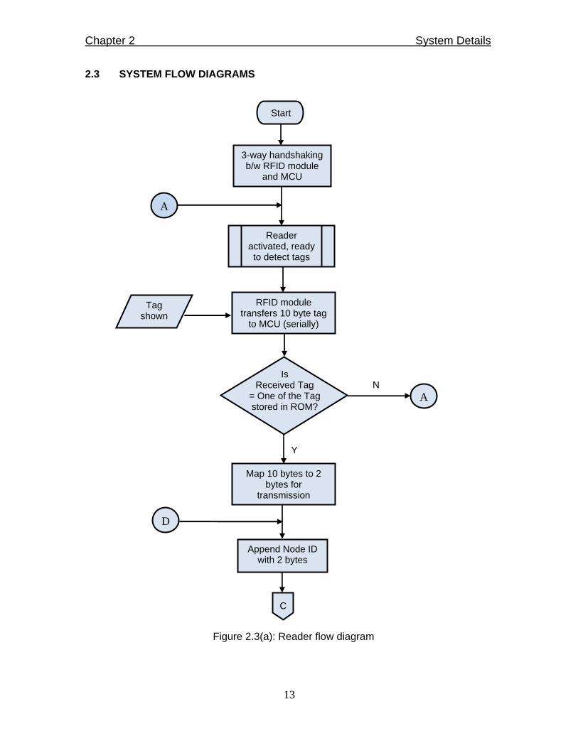
2.3 SYSTEM FLOW DIAGRAMS
Start
3-way handshaking b/w RFID module
and MCU
Reader activated, ready to detect tags
Tag shown
RFID module transfers 10 byte tag
to MCU (serially)
Is Received Tag
= One of the Tag stored in ROM?
A
A
N
Y
Map 10 bytes to 2 bytes for
transmission
Append Node ID with 2 bytes
D
C
Figure 2.3(a): Reader flow diagram

Chapter 2 System Details
14
C
Is
Acknowledgement received?
Indicate Ack
A
Y
N
Is
Retransmit Count > 3?
Y
N
D
Delay
B
Broadcast using ZigBee
Figure 2.3(b): Reader flow diagram
Chapter 2 System Details
15
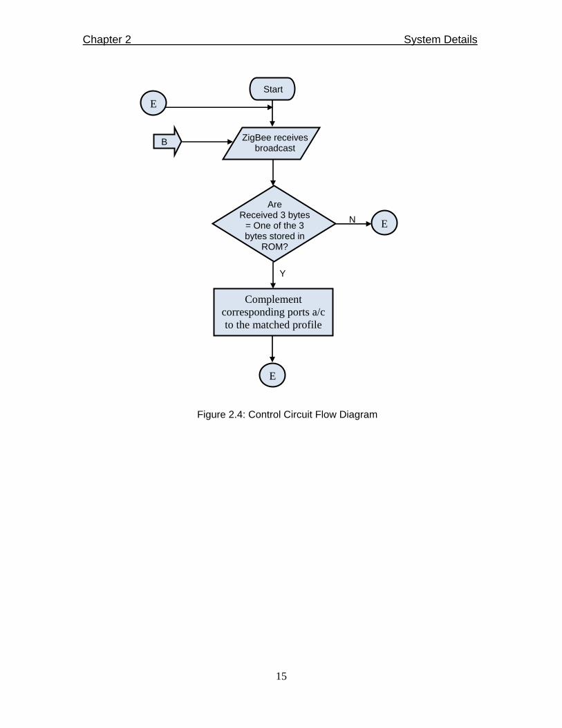
Start
B ZigBee receives broadcast
Are
Received 3 bytes = One of the 3 bytes stored in
ROM?
Complement corresponding ports a/c to the matched profile
E
E
Y
N
Figure 2.4: Control Circuit Flow Diagram
E

Chapter 2 System Details
16
2.4 NETWORK BLOCK DIAGRAM
Figure 2.5: Network Block Diagram
SCENARIO
• Reader will detect the RFID card and forward that ID to microcontroller
• Microcontroller will authenticate the ID and generate a specific number (3 byte code)
against that ID
• This specific number is then forwarded to the ZigBee transceiver via serial link from
where it is broadcast to receiving nodes
• One of the receiving node is the database server where attendance record is
managed

Chapter 2 System Details
17
• At the same time control circuit node receives the broadcast and automates the
office equipments based on that specific profile. The profiles can be modified from
the server as they are stored in NVRAM
• In order to simulate the multi node environment, there is a dummy node that
simulates the working of the RFID reader
• A separate control circuitry (labeled as room 2) is attached with it. This is a hard
wired link

Chapter 3 Selection of Technologies
18
CHAPTER 3
SELECTION OF TECHNOLOGIES
3.1 SELECTION OF TECHNOLOGIES
The two main choices regarding technologies that have been made were of
Microcontroller and Wireless Transmission Standards. Selection of these technologies
was based on the following factors:
• Application
• Cost
• Availability
• Compatibility
• Future enhancement
The details of different models of Microcontroller and available wireless standards
follows, it also provides the reasons for choosing the appropriate technology.
3.1.1 MICROCONTROLLERS
• AT89C51
• ATMEGA 8
AT89C51
89C51 is the member of 8051 family. AT89C51 is a low power, high performance CMOS
8-bit microcontroller with 4Kbytes of Flash programmable and erasable read only
memory (PEROM). This device is compatible with the industry standard 8051 instruction
set and pin outs. The on-chip Flash allows the program memory to be quickly

Chapter 3 Selection of Technologies
19
reprogrammed using a nonvolatile memory programmer. By combining an industry
standard 8-bit CPU with Flash on a monolithic chip, the 8951 is a powerful
microcomputer which provides a highly flexible and cost effective solution to many
embedded control applications. The 8951 provides the following features [9], [20]:
• 4 Kbytes of Flash
• 128 bytes of RAM
• 32 I/O lines
• Two16-bit timer/counters
• Five vector, two-level interrupt architecture
• Full duplex serial port ~ on chip oscillator and clock circuitry
Figure 3.1: AT89c51
ATMEGA 8
The ATmega8 is a low-power CMOS 8-bit microcontroller based on the AVR RISC
architecture. By executing powerful instructions in a single clock cycle, the ATmega8
achieves throughputs approaching 1 MIPS per MHz, allowing the system designer to

Chapter 3 Selection of Technologies
20
optimize power consumption versus processing speed. The ATMEGA 8 provides the
following features [10]:
• 8 Kbytes of Flash
• 1024 bytes of RAM
• 23 I/O lines
• Two 8-bit timer/counters and one 16 bit timer/counter
• Full duplex serial port ~ on chip oscillator and clock circuitry
Figure 3.2: ATMEGA8
WHY AT89C51?
• COMPUTING NEEDS
o ATMEGA8 has many built in features in it like analog to digital converter,
Crystal etc. But in this project we don’t need those extra features
o We are using 64 bits capacity ID cards in this project. Therefore 4Kbytes
flash memory of AT89c51 can easily store 40-50 such IDs

Chapter 3 Selection of Technologies
21
• COST
o AT89c51 is much cheaper than AVR microcontrollers (ATMEGA8)
• MICROCONTROLLER PROGRAMMER
o AT89c51 programmers are easily available in the local market where as AVR
(ATMEGA8) programmers are not available in the market
• RESOURCES AVAILABILITY
o AT89c51 resources are easily available in different books and on internet
also
3.1.2 WIRELESS STANDARDS
Wireless Transmission is required between the RFID reader and the database server
(PC), where attendance will be managed.
There are various wireless technologies available, each having its own advantages and
disadvantages. We surveyed various Wireless Communication standards. We also
probed in various alternatives present from the different vendors. Our requirement was
to choose a low power wireless standard with permissible range; following is the brief
summary of them.
WI-FI
Wireless fidelity (Wi-Fi) is a wireless networking protocol developed by the IEEE 802.11
working group. Wi-Fi technology uses a spectrum in the 2.4 GHz range, which is the
public radio frequency ISM band, to exchange the data at the broadband speed.
Main features of Wi-Fi include:

Chapter 3 Selection of Technologies
22
• Wi-Fi users can connect to the network sensor and to the internet when in the
proximity of an Access Point (AP)
• Supports Mesh Networking
• Peer to Peer Connectivity
Wi-Fi devices consume relatively high power as compared to other wireless networks.
Besides power consumption they have limited range of up to 45 meters (indoors) to 90
meters (outdoors). Wi-Fi cannot do collision detection [16].
WIBREE
Wibree is the most recent interoperable wireless communication technology introduced
by Nokia that is a competitor of IEEE 802.14.4 in terms of low power consumption and
low cost. Like other wireless standards it utilizes 2.4 GHz Radio Spectrum and transmits
data over a very short range of 10 meter. Therefore, Wibree cannot go head to head
with the ZigBee in applications where more range is required [17].
Applications and main features are:
• Share files between PC and PDA
• Transmitting a signal from remote control to television
• It transmit data up to 1Mbps
BLUETOOTH
Bluetooth is an IEEE 802.15.1 standard that enables a short wireless connection to
communicate between two devices when they are in close proximity to each other and
don’t require high bandwidth.

Chapter 3 Selection of Technologies
23
Characteristic And Main features are:
• A Bluetooth PAN is composed of up to 8 active devices in a master-slave relation
ship
• The Bluetooth protocol divides the bandwidth into 79 channels
• Each channel has a centre frequency of 1 MHz
• A Bluetooth enable wireless device is capable making phone calls, synchronizing
data with desktop computers, sending and receiving faxes, and printing documents
[11].
WHY ZIGBEE?
We selected ZigBee because of its low power consumption, low cost and moderate
range 30 m to 1.6 Km. This range is suitable for our application where we want to
wirelessly transmit data from RFID reader to the Database Server, where attendance is
being managed. Another most important reason for using ZigBee module is that these
modules come with serial interface therefore it will be easier for us to use these
modules.
These low-Rate WPAN standards have exceedingly secured wireless transmission over
a very distant range. In the 2.4 GHz band there are 16 ZigBee channels, with each
channel requiring 5 MHz of bandwidth [18], [19].
Pin description of ZigBee module is illustrated in table 3.1

Chapter 3 Selection of Technologies
24
Table 3.1: ZigBee Pin description
Figure 3.3: ZigBee pin configuration

Chapter 3 Selection of Technologies
25
3.2 SELECTION OF SOFTWARE TOOL
The Selection of software tool was made by comparing the different programming
languages and came up to a conclusion of using C# for the database server.
Currently Microsoft is offering four languages out of the box: C#, VB.Net, Managed C++
and Jscript for application development on .Net platform and many more to come from
various independent vendors. So the obvious question is which language is best suited
for .Net? Here is a brief discussion on the above topic.
JSCRIPT
Nobody in the current market is talking about Jscript (found in the quick start only) and
most programmer strongly believe JScript to end up with a very small user base. It’s not
advisable to go with Jscript, despite it being cool.
MANAGED C++
C++, even in its new managed form, definitely lags behind other languages such as
VB.NET and C# for their cleaner syntax and ease of use. There's no doubt, though, that
experienced C++ practitioners will continue to admire and use its power, templates,
multiple code inheritance and deterministic finalization.
C#
C# is the new language with the power of C++ and the slickness of Visual Basic. It
cleans up many of the syntactic peculiarities of C++ without diluting much of its flavor
(thereby enabling C++ developers to transition to it with little difficulty). And its
superiority over VB6 in facilitating powerful object oriented implementations is without
question. C# with clean object oriented syntax and large class library (in conjunction with

Chapter 3 Selection of Technologies
26
.NET and the base class libraries) could be the ‘most productive mainstream language’
and it is an ECMA (European Computer Manufacturers Association.) standard language
that offers the potential of being available across many platforms. For the serious
developer wanting Microsoft's most productive and mainstream .NET language, C# is
the clear choice.
VB.NET
VB Developers over the years have been asking for more power (inheritance and
polymorphism). Now VB.Net provides all that and it’s now a fully-fledged object oriented
language. To the question 'Whether to choose VB.Net or C#' - The answer has been
'Use the one with which you are comfortable with'.
It's said that VB.Net is there only to please those millions of VB6 Developers and nothing
else. But as I said before, VB.NET is an object oriented language and VB6 is not. So the
problem is that if you're not thinking object oriented, you're probably not going to enjoy
the VB.NET (from VB6) transitioning experience coz this is more than just a syntax shift.
There is one more problem, some expert claims that you have to write 33% more Lines
of Code in VB.Net than C# (Nothing Official).
If you're looking for the safest bet, hitch a ride with C#. Sure VB.NET is now just as
powerful and C++ remains even more so, but for the reasons we've described of
productivity, clarity and a broad community, you won't regret it therefore we choose C#
for our application [12].

Chapter 4 System Hardware: Reader Node
27
CHAPTER 4
SYSTEM HARDWARE: READER NODE
Reader node can be divided into four main components as shown in figure 4.1
• RFID module
• Microcontroller (AT89c51)
• ZigBee module
• Port switching circuit
4.1 RFID READER WORKING
• An RFID module typically contains a transmitter and receiver, a control unit and a
coupling element (antenna).
Figure 4.1: Reader node Schematic

Chapter 4 System Hardware: Reader Node
28
• The reader has three main functions: energizing, demodulating and decoding.
Information is sent to and read from RFID tags by a reader using radio waves.
• Passive RFID tags have no internal power supply. The minute electrical current
induced in the antenna by the incoming radio frequency signal (125 KHZ)
provides just enough power for the CMOS integrated circuit in the tag to power
up and transmit a response.
• Most passive tags signal by backscattering (Backscatter is the reflection of
waves, particles, or signals back to the direction they came from) the carrier
wave from the reader, as shown in figure 4.2
Figure 4.2: RFID backscatter
• Passive tags have practical read distances ranging from about 10 cm (4 in.)
• Data collected from tags (10 bytes) is then passed through communication
interfaces (cable or wireless) to host computer systems in the same manner that
data scanned from bar code labels is captured and passed to computer systems
for interpretation, storage, and action.

Chapter 4 System Hardware: Reader Node
29
4.2 MICROCONTROLLER WORKING
• HAND SHAKING
o On power-up reader sends an activation string to the microcontroller
o After receiving the activation string microcontroller sends an encoded
string to the reader which is provided by the vendor. The string is of 16
bytes
o The encoded string is” �re364 � � acknwlge”
o Reader responds with an acknowledgement string 24 bytes long,
indicating the microcontroller that it is ready to read
• ID EXTRACTION
o Whenever RFID card is in the vicinity (4 in.) of a reader it will extract the
ID (refer 4.1 for details) and serially transfer (10 byte) it to the
microcontroller
o Microcontroller will save it in its RAM and wait for 3 seconds. This waiting
time avert the microcontroller from reading the same ID twice
o Microcontroller than starts comparing (byte by byte) the received ID with
the IDs stored in its ROM
• TAGGING
o After ID authentication microcontroller will map 10 byte card ID on a 2
byte tag# so that it can efficiently utilize the transmission time
o Transmission time at 9600 baud rate of
10 bytes: T= (1/9600)*80=8.33 msec

Chapter 4 System Hardware: Reader Node
30
2 bytes: T= (1/9600)*16=1.6 msec
So it means we are saving more than 80% of the transmission time by
using tagging technique
o In multi node environment transmission time is directly related with the
system performance. More the transmission time higher will be the
probability of data collision and vice versa
o Like RFID cards, tag numbers are also unique
o In microcontroller’s ROM these IDs are saved in a 12 byte fashion as
illustrated in fig 4.3
Figure 4.3: Tagging
o After ID verification microcontroller extract its tag# for transmission
• TRANSMISSION
o Before forwarding tag# to the ZigBee module microcontroller append one
byte of node ID before tag#
o This node ID is used to pinpoint the card location
o Microcontroller than serially transmits 3 byte of data (containing 1 byte of
node ID and 2 bytes of tag#) and wait for the acknowledgement from the
server
o The waiting time of every node is unique because waiting time is
dependent upon its node ID. This is done to avoid data collision between
nodes
Chapter 4 System Hardware: Reader Node
31
o If microcontroller doesn’t receive acknowledgement from the server it will
retransmit the node ID and tag# and again wait for the acknowledgement.
The re-transmit limit of every node is 3
o Whenever we push a button on dummy node it transmit a fixed fake node
ID and tag#
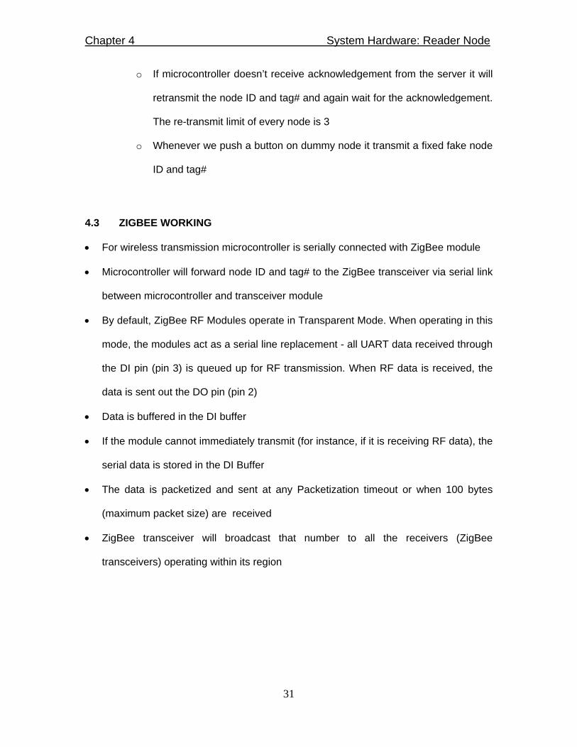
4.3 ZIGBEE WORKING
• For wireless transmission microcontroller is serially connected with ZigBee module
• Microcontroller will forward node ID and tag# to the ZigBee transceiver via serial link
between microcontroller and transceiver module
• By default, ZigBee RF Modules operate in Transparent Mode. When operating in this
mode, the modules act as a serial line replacement - all UART data received through
the DI pin (pin 3) is queued up for RF transmission. When RF data is received, the
data is sent out the DO pin (pin 2)
• Data is buffered in the DI buffer
• If the module cannot immediately transmit (for instance, if it is receiving RF data), the
serial data is stored in the DI Buffer
• The data is packetized and sent at any Packetization timeout or when 100 bytes
(maximum packet size) are received
• ZigBee transceiver will broadcast that number to all the receivers (ZigBee
transceivers) operating within its region

Chapter 4 System Hardware: Reader Node
32
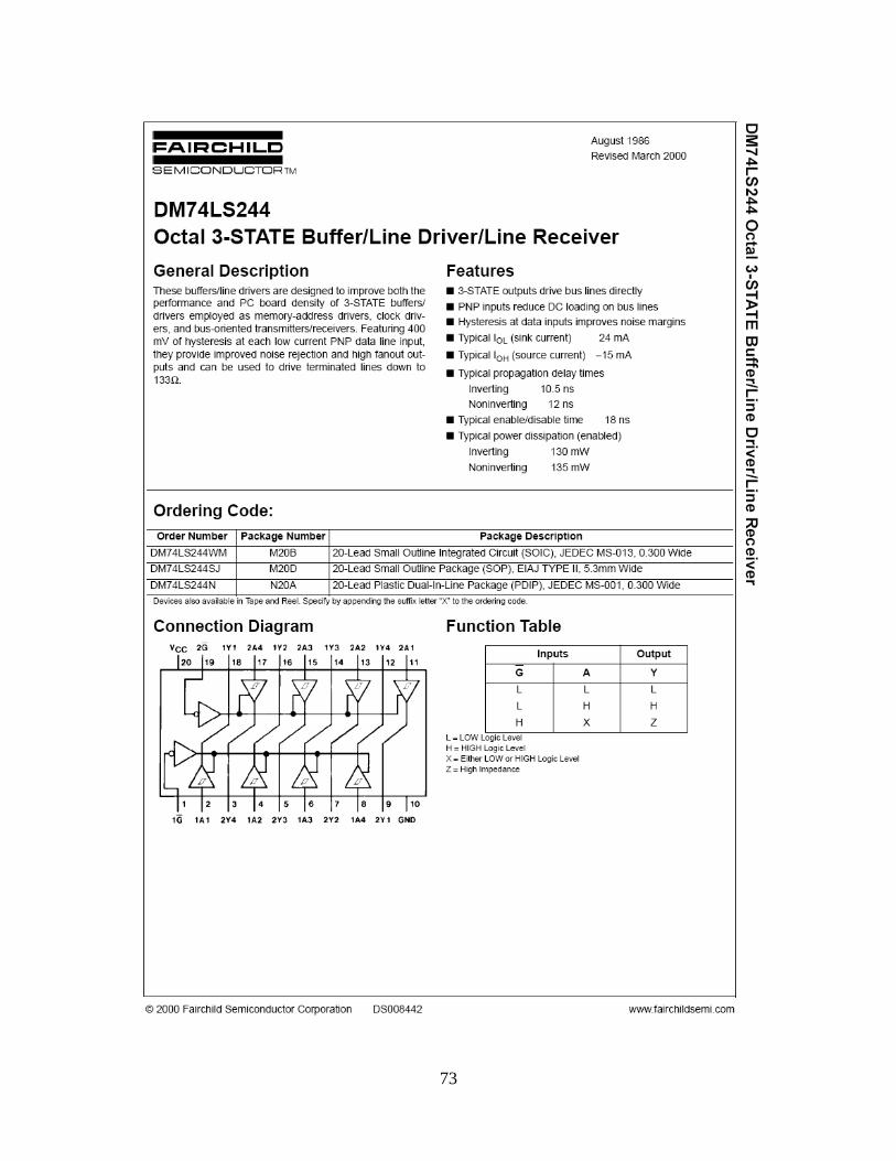
4.4 PORT SWITCHING CIRCUIT
• The microcontroller AT89c51 has one serial port (i.e. one Tx and one Rx pin), but the
line driver (max232) used between microcontroller and DB9 connecter can support
two serial ports
• To avoid tapping (interfacing ZigBee and RFID module through same port), 3-state
buffer (74ls244) is used
• 74ls244 has two enable pins (pin 1 and 19), each pin can control the four input-
output pair associated with it, as shown in figure 4.4(a)
• When these pins are high, the output is in high impedance state. Pin 1 is reserved for
RFID module and pin 19 for ZigBee module.
• When the output is intended for particular device corresponding pin is set low
(enable pins are active low as shown in figure 4.4(b)) through the assembly program
burned in microcontroller
Figure 4.4(a): 74ls244 connections Figure 4.4(b): 74ls244 truth table

Chapter 4 System Hardware: Reader Node
33
4.5 DUMMY NODE
• To simulate multinode environment we are using dummy node
• Dummy node is also operating in the same fashion as reader node
• Dummy node is not interfaced with the RFID reader, instead it has push buttons as
shown in figure 4.5
• Each push button generates a Tag # which simulates as if real Tag was shown
Figure 4.5: Dummy node schematic

Chapter 5 System Hardware: Control Circuitry
34
CHAPTER 5
SYSTEM HARDWARE: CONTROL CIRCUITRY
5.1 INTRODUCTION
Control circuitry is one of the vital part of the project. The control circuitry is basically
used for the room automation, the room automation can be personalized or kept as
default.
5.2 COMPONENTS
1) ZigBee
2) MAX 232
3) Microcontroller
4) Buffer
5) Optocoupler
6) NPN Transistor
7) Relay
5.3 WORKING
• ZigBee receives the 3byte data (Node + Card ID)
• ZigBee transceiver sends the data to the microcontroller via MAX 232 IC (line
driver)used for protocol translation from RS 232 to TTL and vice versa
• The translated data is read by the microcontroller via a serial link
• The microcontroller compares the card and node ID with the ID stored in its
memory

Chapter 5 System Hardware: Control Circuitry
35
• Every ID stored in the microcontroller’s memory has a specific room to be
automated against it
• The room itself has it own profile
• The default profile is to switch every AC load controlled by the microcontroller
• In other case the profile can be personalized according to the user ID
• The microcontroller is connected to the relays via a switching circuitry
• Switching circuitry consists of 3 components Buffer, Optocoupler and Relay
• Buffer is used to amplify the output current of the microcontroller
• The optocoupler is used to isolate the vital components (ZigBee and
Microcontroller) from the reverse current
• Optocoupler is a device that uses a short optical transmission path to transfer a
signal between elements of a circuit, typically a transmitter and a receiver, while
keeping them electrically isolated, as illustrated in Figure 5.1
Figure 5.1: Optocoupler
• The output current is proportional to the amount of incident light supplied by the
emitter

Chapter 5 System Hardware: Control Circuitry
36
• As the current across the phototransistor increases it goes to the NPN transistor
which is used as an amplifier to drive the relay
• A relay is an electrical switch that opens and closes under the control of another
electrical circuit
• When the current flows through the relay coil, the resulting magnetic field attracts
an armature that is mechanically linked to a moving contact, as illustrated in
Figure 5.2
Figure 5.2 Relay schematic diagram
• The moving armature makes a connection with a fixed contact resulting in the
switching of power line on to the AC load

Chapter 5 System Hardware: Control Circuitry
37
5.4 WHY MICROCONTROLLER?
Table 5.1: Microcontroller and Microprocessor comparison
MICROCONTROLLER MICROPROCESSOR
• Microcontrollers incorporate
program memory, ram memory and
input/output resources internal to
the chip. Microchip's pic series and
Atmel's AVR series are examples
of microcontrollers
• Microcontrollers are usually
designed to perform a small set of
specific functions, for example as in
the case of a Digital Signal
Processor which performs a small
set of signal processing functions
• Microcontrollers are widely used in
modern cars where they will each
perform a dedicated task, i.e. a
microcontroller to regulate the
brakes on all four wheels, or a
microcontroller to regulate the car
air conditioning
• Microprocessors generally require
external components to implement
program memory, ram memory and
Input/output. Intel's 80186, 80188,
and 80386 are examples of
microprocessors
• Microprocessors tend to be
designed to perform a wider set of
general purpose functions
• Microprocessor in a PC which
performs a wide range of tasks
related to the general requirements
of a PC, i.e. performing the
necessary calculations for a very
wide set of software applications,
performing I/O for the main sub-
systems, peripheral control etc

Chapter 5 System Hardware: Control Circuitry
38
Table 5.2: Microcontroller and PLC comparison
MICROCONTROLLER PLC
• Micro-controller
is smaller and well suited for
embedded situations
• Micro controller
has a very different programming
language, assembly, basic, etc.
• MCU) are complete computer
systems on a chip. They combine
an arithmetic logic unit (ALU),
memory, timer/counters, serial port,
input/output (I/O) ports and a clock
oscillator.
• PLC is used in an industrial
environment
• PLC is programmed
in "Ladder Logic" which
appears very similar to
industrial schematics.
• PLC is the control hubs for
automated systems NAD
processes. They contain
multiple inputs and outputs that
use transistors and other
circuitry to simulate switches
and relays to control equipment.
They're also programmable via
standard computer interfaces
and proprietary languages and
network options.
The main reasons for using microcontroller over programmed logic controllers and
microprocessor are as follows:
• Cheapest among the three components

Chapter 5 System Hardware: Control Circuitry
39
• Used for embedded situations
• References and resources are easily available
5.5 CONTROL CIRCUIT SCHEMATIC
Figure 5.3(a): Control circuit schematic (Receiver part)

Chapter 5 System Hardware: Control Circuitry
40
Figure 5.3(b): Control circuit schematic (Automation part)
5.6 CONTROL CIRCUITRY WITH NVRAM
• To give this project flexibility we are using NVRAM with the control circuitry. Due
to time constraint we are unable to implement this idea with our reader node
• NVRAM give us the opportunity to modify user’s profile on the run time without
making any changes in the hardware
• NVRAM is a combination of RAM and ROM. Non-volatile random access
memory (NVRAM) is the general name used to describe any type of random
access memory which does not lose its information when power is turned off
5.6.1 MODIFICATION IN USER’S PROFILE
• Administrator can modify user’s profile by a separate program on the server. He
can select any profile for modification. To modify the selected profile our program

Chapter 5 System Hardware: Control Circuitry
41
will send a unique string of six bytes. Each node will receive this string and
perform modification according to the string code.
• First byte will inform the nodes that administrator wants to modify the profile
• Second byte will contain the node ID. If administrator wants to modify the profile
on all nodes than it will contain code number 99H
• Fourth and fifth byte is of card ID and sixth byte contains the profile number as
illustrated in figure
• To keep other nodes synchronized with the server the modification program
transmit these 6 bytes into two 3 byte chunks
Node ID 99H 00H Card ID (2 Bytes) Profile #

Chapter 5 System Hardware: Control Circuitry
42
5.7 CONTROL CIRCUIT WITH NVRAM SCHEMATIC
Figure 5.4: Control circuit with NVRAM schematic

Chapter 6 Software Design
43
CHAPTER 6
SOFTWARE DESIGN
6.1 SOFTWARE INTRODUCTION
The “Smart Attendance System” is an application for this project’s database server. This
application maintains the attendance record against unique IDs assigned to RFID card
holders and also provides facility to add/edit the user profile specified in control circuit
RAM.
6.2 SAS MAIN FEATURES
• SAS (Smart Attendance System) will continuously read data which is provided by
the RFID reader.
• It maintains the attendance in database made on Microsoft Access.
• It maintains profiles against unique Ids.
The profile has various fields
o Name
o Email Address
o Phone Number
o Room Number
• It maintains the daily record of attendance
• It provides option of search profiles by name, ID and email
• It also provides the option to see the attendance record according to calendar
• It also makes a graph of each card holder’s check in and checkout timings
• This application has also many checks and balances which makes it more
secure. For example
o It prevents a card holder to check in at two places simultaneously.

Chapter 6 Software Design
44
o It marks attendance if and only if a card holder spent a minimum time
required for attendance. Like if minimum requirement for a attendance to
be marked is 3 hours it means a card holder must spent 3 hours in office
otherwise his/her attendance will not be marked by the system.
6.2.1 WORKING OF SOFTWARE
The SAS has two modes of operation
• Standard Mode
• Admin Mode
6.2.2 STANDARD MODE
In standard mode daily record of attendance appears. Each log has the information
about node ID, card ID, entrance time, exit time, time spent and date of that log.
Figure 6.1: Snapshot of standard mode
Chapter 6 Software Design
45
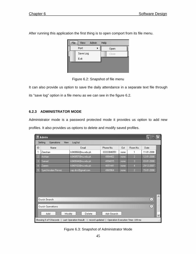
After running this application the first thing is to open comport from its file menu.
Figure 6.2: Snapshot of file menu
It can also provide us option to save the daily attendance in a separate text file through
its “save log” option in a file menu as we can see in the figure 6.2.
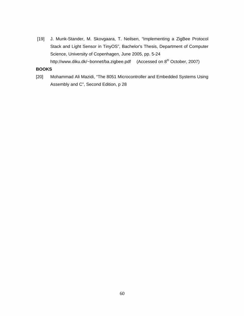
6.2.3 ADMINISTRATOR MODE
Administrator mode is a password protected mode it provides us option to add new
profiles. It also provides us options to delete and modify saved profiles.
Figure 6.3: Snapshot of Administrator Mode

Chapter 6 Software Design
46
(a) HOW TO ADD A PROFILE?
The SAS provides us very simple and easy way to add new profiles.
There are two ways to add new profile
• By click on “ADD” button in quick operations pane as shown in figure 6.4
• By the help of operations menu as shown in figure 6.5(a),(b) and (c)
Figure 6.4: Snapshot of Add profile window
Figure 6.5(a): Snapshot of operations menu

Chapter 6 Software Design
47
Figure 6.5(b): Before Adding a new profile
Figure 6.5(c): After Adding a new profile

Chapter 6 Software Design
48
(b) HOW TO MODIFY A PROFILE?
The SAS provides us very simple and easy way to modify previously stored profiles.
There are two ways to modify previously stored profile
• By click on “MODIFY” button in quick operations pane
• By the help of operations menu
At first, select the profile by clicking on it and then press modify button as shown in figure
6.6.
Figure 6.6: Snapshot of Admin mode

Chapter 6 Software Design
49
Figure 6.7: Snapshot of modify window
As we can see in the figure 6.7, here we have options to modify any detail of selected
profile.
For example If we change the name “Arshian” to “Arshian Ahmed”, we just need to
change the name field in modify window as shown in figure 6.8.
Figure 6.8: Snapshot of modify window (after modification)
After pressing the button named “Modify” we can observe the change in profile name in
admin window as shown in figure 6.9.

Chapter 6 Software Design
50
Figure 6.9: Snapshot of Admin mode
(c) HOW TO DELETE A PROFILE?
The SAS provides us very simple and easy way to delete previously stored profiles.
There are two ways to delete a profile
• By click on “Delete” button in quick operations pane
• By the help of operations menu
Figure 6.10: Snapshot of Delete window

Chapter 6 Software Design
51
If we press the button named “DELETE” in the delete record window as shown in figure
6.10, we observe the removal of that record which we have deleted.
Figure 6.11a: Before deleting user profile

Chapter 6 Software Design
52
Figure 6.11b: After deleting user Profile
6.3 SYSTEM REQUIREMENTS FOR SAS
To run “Smart Attendance System” following are the basic requirements
• Windows XP/VISTA (XP with service pack 2)
• .Net Frame work 3.5
• 128 Mb of RAM (minimum)
• 1 GHZ Processor (minimum)
6.4 SERIAL PORT TERMINAL
To frequently test RFID reader and project’s hardware we have made another program
with a name of “Serial Port Terminal” as shown in figure 6.12. This program is solely
made for testing purpose.

Chapter 6 Software Design
53
Figure 6.12: Snapshot of Serial Port Terminal
• It can read data automatically we don’t have to press any button for reading data
from serial buffer
• It has a facility to set particular com port, baud rate, parity, data bits and also stop
bits
• We can send and receive and data in text as well as Hex format
• Before start our communication we have to open serial port by pressing “open port”
button
• It dump node Id and card Id separately in a text file along with the system time as
shown in figure 6.13.

Chapter 6 Software Design
54
Figure 6.13: Snapshot of text file records of SerialPort terminal

Chapter 7 Cost Analysis
55
CHAPTER 7
COST ANALYSIS
Table 7.1: Cost analysis
SYSTEM PARTS
COST (Rs.)
READER NODE
• RFID reader module
• Microcontroller
• ZigBee module
• Miscellaneous
9500
70
Provided by University
800
DUMMY NODE
• Microcontroller
• ZigBee module
• Miscellaneous
70
Provided by University
600
CONTROL CIRCUITRY
• Microcontroller
• Relays
• Zigbee module
• Miscellaneous
• NVRAM
70
200
Provided by University
600
350
SERIAL CABLES
• Few serial cables
200
MICROCONTROLLER BURNER
• Burner for microcontroller
900
TOTAL Rs.13360/-
* Miscellaneous includes resistors, capacitor, switches, max232 etc, plus the project casing for presentation purpose.

Chapter 8 Conclusion and Future Work
56
CHAPTER 8
CONCLUSION AND FUTURE WORK
8.1 CONCLUSION
The objective of this project that is “RFID based Smart Office” was to design a system
based on RFID technology that will not only change the hectic manual attendance
procedure but also automate user’s office.
The final design of the project accomplished the idea of multinode environment which is
responsible for automatic attendance and office automation according to the
personalized profile of the RFID card holder. The design also deals with the issues
(reliable data transfer) of multinode environment. To make sure reliable data transfer
between server and reader node the project adopts CSMA/CD algorithm.
This project facilitates the users in numerous ways like time saving in attendance
procedure, security, employees’ attendance management and many more.
8.2 FUTURE WORKS
With the coming availability of low cost, short range radios along with advances in
wireless networking, it is expected that wireless ad hoc sensor networks will become
commonly deployed. This project can be improvised by using external memory because
the project design has a capability of handling 65000 card IDs which is large enough for
any organization but the limitation lies in the microcontroller storage capacity. This
limitation can be overcome by the use of NVRAM with the reader node which will not
only make the design scalable but also flexible. NVRAM not only provide us extra
memory but also enable us to add cards IDs on the run time.

Chapter 8 Conclusion and Future Work
57
Furthermore, this project can be extended by making nodes IP enabled so that it can be
accessed virtually from any where. There is also some space to improve the project
code.

58
REFERENCES
INTERNET [1] KORTEX PSI Point Of Sale & Industry
http://www.korteks.com/Applications/Applications_TOC.htm (Accessed on
2nd September, 2007)
[2] VIRADIX: The smart choice for E-commerce consulting
http://www.viradix.com/terminology.html (Accessed on 2nd September, 2007)
[3] Texas A&M Engineering
http://engineer.tamu.edu/research/magazine/2006/robots/ (Accessed on 2nd
September, 2007)
[4] Moxa Success Story – Attendance Recording System
http://www.moxa.com/solutions/success_stories_Attendance_Recording_System.htm
(Accessed on 5th September, 2007)
[5] Selvam Systems Pvt Ltd-Computer, Computer software Project
http://www.alibaba.com/member/203023.html (Accessed on 5th September,
2007)
[6] Federal Bureau of Investigation
http://www.fbi.gov/hq/cjisd/iafis.htm (Accessed on 16th April, 2007)
[7] Information Security: Covering Today’s Security Topics
http://searchsecurity.techtarget.com/sDefinition/0,,sid14_gci812929,00.html
(Accessed on 16th April, 2007)
[8] RFID-FDA-Regulations
http://www.bin95.com/RFID-FDA-Regulations.htm (Accessed on 16th April, 2007)
[9] Atmel Corporation, www.atmel.com/products/8051/ (Accessed on 4th October,
2007)

59
[10] AVR freaks
http://www.avrfreaks.net/index.php?module=Freaks%20Devices&func=
displayDev&objectid=52 (Accessed on 4th October, 2007)
[11] The Official Bluetooth Technology Info Site, http://www.bluetooth.com (Accessed
on 8th October, 2007)
[12] Overview - Why C# ?, http://www.csharphelp.com/archives/archive73.html
(Accessed on 2nd October, 2007)
PAPERS [13] Dr. Jeremy Landt “Shrouds of Time: The history of RFID”, White Paper, AIM Inc,
October 2001, pp. 3-7. http://www.transcore.com/pdf/AIM%20shrouds_of_time.pdf
(Accessed on 16th April, 2007)
[14] Fisher, Jill A. “Indoor Positioning and Digital Management: Emerging
Surveillance Regimes in Hospitals”. In T. Monahan (Ed), Surveillance and
Security: Technological Politics and Power in Everyday Life, 2006, pp. 77–88.
http://www.jillfisher.net/papers/rfid.pdf (Accessed on 16th April, 2007)
[15] Fisher, Jill A. and Monahan, Torin. “Tracking the Social Dimensions of RFID
Systems in Hospitals”.International Journal of Medical Informatics, April 2007,
pp.176-183.
http://torinmonahan.com/papers/Fisher_Monahan_RFID_IJMI.pdf (Accessed on
16th April, 2007)
[16] Paul S. Henry, “Is Wi-Fi in Your Future? ”, AT&T Labs – Research, 2002, pp.1-19
http://www.comsoc.org/confs/ieee-infocom/2002/non-image_files/
Infocom2002%20Keynote-short.pdf (Accessed on 8th October, 2007)
[17] Nick Hunn, “An introduction to Wibree”, White Paper, Ezurio Ltd, 2002,
pp. 2-7. http://www.ezurio.com/files/00616.pdf (Accessed on 8th October, 2007)
[18] Sinem Coleri Ergen, “ZigBee/IEEE 802.15.4 Summary”, Research Paper,
University of Berkeley, September 2004, pp.1-3
http://pages.cs.wisc.edu/~suman/courses/838/papers/zigbee.pdf
(Accessed on 6th October, 2007)
60
[19] J. Munk-Stander, M. Skovgaara, T. Neilsen, “Implementing a ZigBee Protocol
Stack and Light Sensor in TinyOS”, Bachelor's Thesis, Department of Computer
Science, University of Copenhagen, June 2005, pp. 5-24
http://www.diku.dk/~bonnet/ba.zigbee.pdf (Accessed on 8th October, 2007)
BOOKS [20] Mohammad Ali Mazidi, “The 8051 Microcontroller and Embedded Systems Using
Assembly and C”, Second Edition, p 28

61
APPENDICES
A.1 DATA SHEETS

62
63

64

65

66

67

68

69
70

71

72
73

74

75

76
77

78
A.2 ASSEMBLY CODE: READER NODE ;************************************************************************************************** ;************************************** SETTING TIMER *************************************** ORG 0H MOV TMOD,#20H ;SETTING BAUD RATE 9600BPS MOV TH1,#-3 MOV SCON,#50H SETB TR1 MOV P2,#0H MOV P1,#0H ;************************************************************************************************* CLR P2.3 ;TO ACTIVATE READER PORT SETB P2.4 ;TO DISABLE ZIGBEE PORT ;***************************************** HANSHAKING ************************************* MAIN: MOV R1,#08 REC: JNB RI,REC ;MCU RECIEVES THE MODULE MOV A,SBUF ;POWERED ON STRING CLR RI DJNZ R1,REC SETB P2.0 MOV R5,#36 ;5 SEC DELAY A1: MOV R4,#255 A2: MOV R3,#255 A3: DJNZ R3,A3 DJNZ R4,A2 DJNZ R5,A1 MOV DPTR,#CODED_STRING MOV R6,#16 MCU_SEND: ;MCU SEND THE ENCODED STRING CLR A ;STRING TO MODULE MOVC A,@A+DPTR MOV SBUF,A JNB TI,$ CLR TI INC DPTR DJNZ R6,MCU_SEND SETB P2.1
79
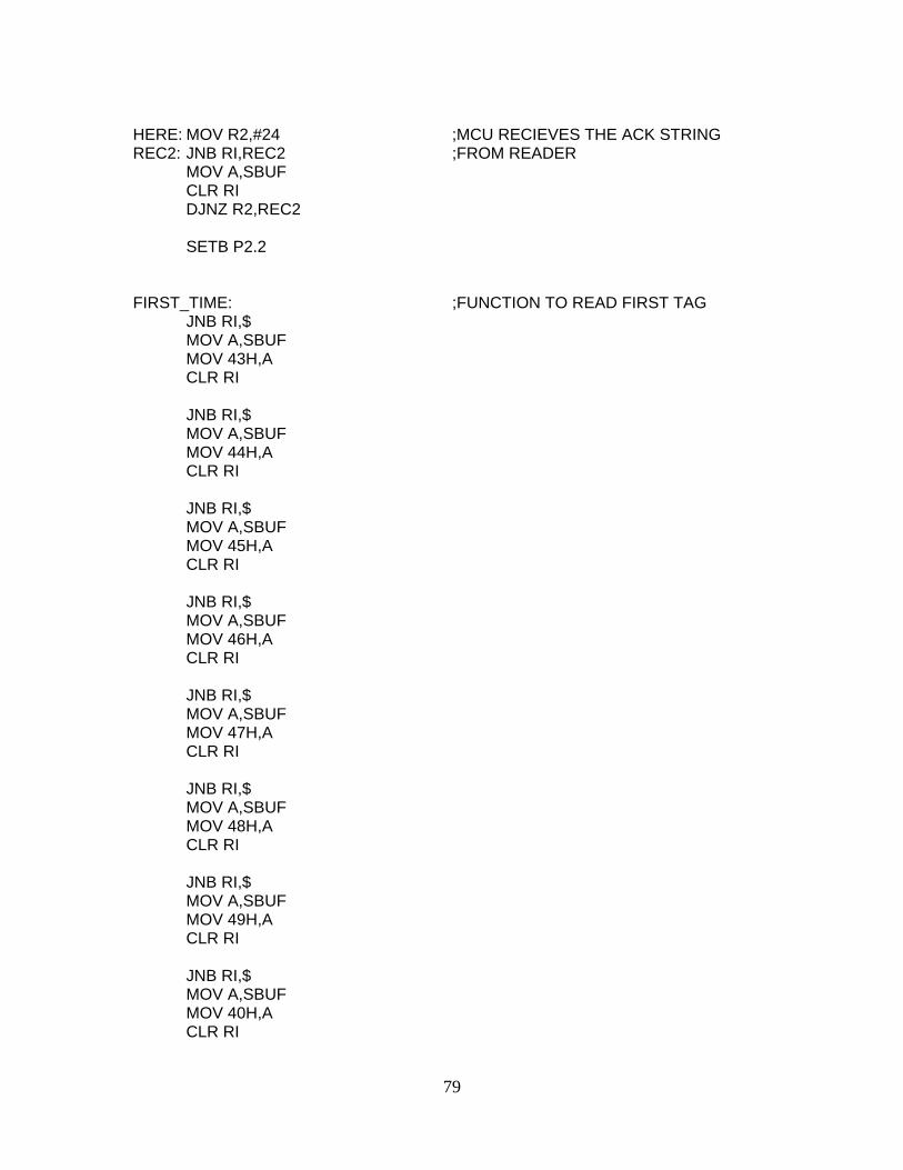
HERE: MOV R2,#24 ;MCU RECIEVES THE ACK STRING REC2: JNB RI,REC2 ;FROM READER MOV A,SBUF CLR RI DJNZ R2,REC2 SETB P2.2 FIRST_TIME: ;FUNCTION TO READ FIRST TAG JNB RI,$ MOV A,SBUF MOV 43H,A CLR RI JNB RI,$ MOV A,SBUF MOV 44H,A CLR RI JNB RI,$ MOV A,SBUF MOV 45H,A CLR RI JNB RI,$ MOV A,SBUF MOV 46H,A CLR RI JNB RI,$ MOV A,SBUF MOV 47H,A CLR RI JNB RI,$ MOV A,SBUF MOV 48H,A CLR RI JNB RI,$ MOV A,SBUF MOV 49H,A CLR RI JNB RI,$ MOV A,SBUF MOV 40H,A CLR RI

80
JNB RI,$ MOV A,SBUF MOV 41H,A CLR RI JNB RI,$ MOV A,SBUF MOV 42H,A CLR RI SETB P1.0 MOV R7,#22H ;CHECK FOR FIRST TAG TO BE READ ;************************************************************************************************* ;*********************************** READ FUNCTION *************************************** TAG_RECIEVE_CMP_MAP_TRANS: ;MAIN FUNCTION CJNE R7,#23H,DELAY CLR P2.3 ;TO ACTIVATE READER PORT SETB P2.4 ;TO DISABLE ZIGBEE PORT MOV R0,#40H
CLR RI ;SAVING THE TAG INTO RAM STARTING TAG: MOV R2,#10 ;AT LOCATION 40H--49H TREC: JNB RI,TREC MOV A,SBUF MOV @R0,A INC R0 CLR RI DJNZ R2,TREC CPL P1.0 DELAY: MOV R7,#23H MOV R5,#22 ;3 SEC DELAY A4: MOV R4,#255 A5: MOV R3,#255 A6: DJNZ R3,A6 DJNZ R4,A5 DJNZ R5,A4 CLR RI MOV DPTR,#TAG1

81
;******************************** COMPARE AND MAP ************************************ COMPARE: MOV R2,#10 MOV R0,#40H MOV R1,#0CH CMP1: CLR A ;COMPARING THE READ TAG WITH MOVC A,@A+DPTR MOV B,@R0 ;THE ONE STORED IN ROM CJNE A,B,MOV_DPTR ;GENERAL AND SCABLE FUNC INC DPTR ;ALSO DOES MAPPING TO 2 BYTES INC R0 DEC R1 DJNZ R2,CMP1 CLR A MOVC A,@A+DPTR MOV R6,A INC DPTR CLR A MOVC A,@A+DPTR MOV R7,A INC DPTR MOV A,#16 ;TO GENERATE RANDOM MOV B,#10 ;RETRANSMIT TIME FOR MUL AB ;EACH NODE LABEL0: MOV R2,#0 SETB P2.3 ;TO DISABLE READER PORT CLR P2.4 ;TO ACTIVATE ZIGBEE PORT LABEL1: CJNE R2,#3,NODE_SEND ;RETRANSMIT CHECK MOV R7,#23H LJMP TAG_RECIEVE_CMP_MAP_TRANS
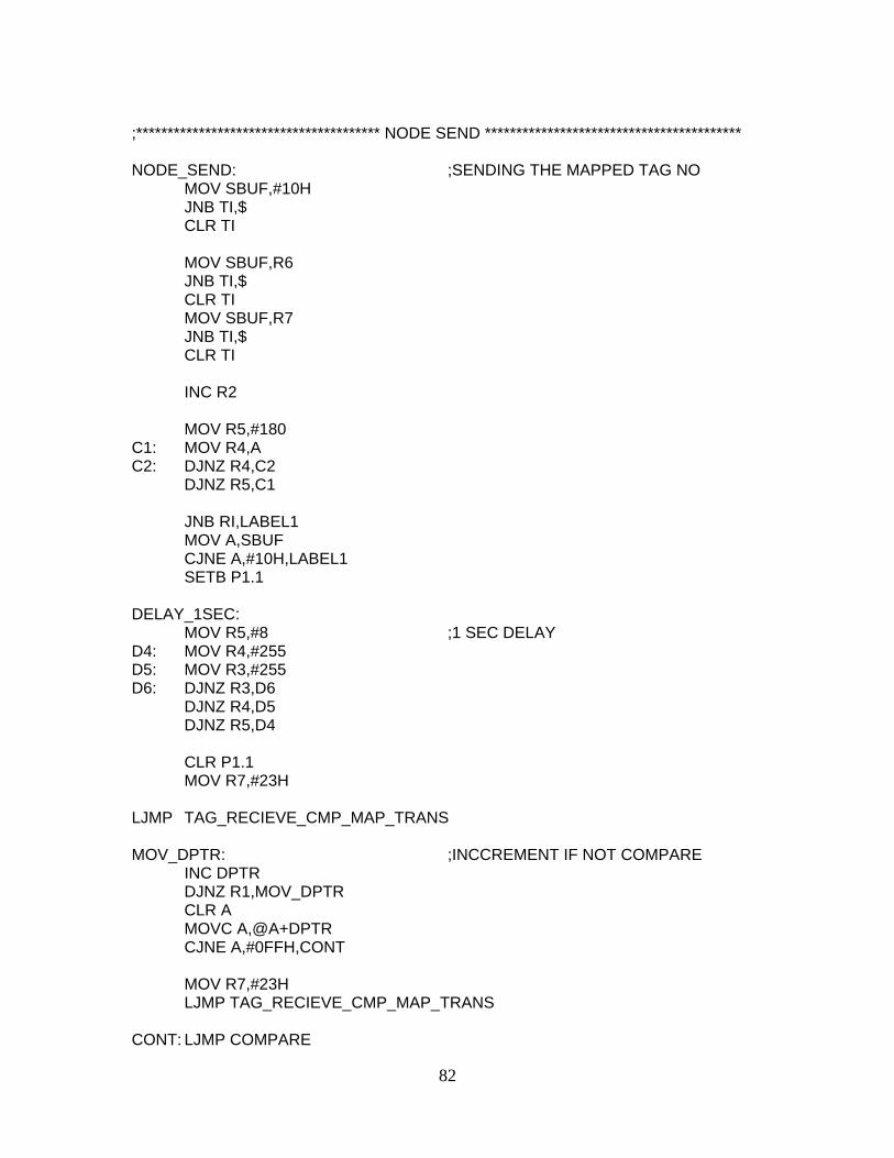
82
;*************************************** NODE SEND ***************************************** NODE_SEND: ;SENDING THE MAPPED TAG NO MOV SBUF,#10H JNB TI,$ CLR TI MOV SBUF,R6 JNB TI,$ CLR TI MOV SBUF,R7 JNB TI,$ CLR TI INC R2 MOV R5,#180 C1: MOV R4,A C2: DJNZ R4,C2 DJNZ R5,C1 JNB RI,LABEL1 MOV A,SBUF CJNE A,#10H,LABEL1 SETB P1.1 DELAY_1SEC: MOV R5,#8 ;1 SEC DELAY D4: MOV R4,#255 D5: MOV R3,#255 D6: DJNZ R3,D6 DJNZ R4,D5 DJNZ R5,D4 CLR P1.1 MOV R7,#23H LJMP TAG_RECIEVE_CMP_MAP_TRANS MOV_DPTR: ;INCCREMENT IF NOT COMPARE INC DPTR DJNZ R1,MOV_DPTR CLR A MOVC A,@A+DPTR CJNE A,#0FFH,CONT MOV R7,#23H LJMP TAG_RECIEVE_CMP_MAP_TRANS CONT: LJMP COMPARE

83
;********************************** STORED TAGS IN ROM********************************** ORG 300H ;STORING TAG NO. IN ROM TAG1: DB "06000707AD" ;ORIGNAL TAG MYTAG1: DB 00H,01H ;MAPPED TAG NO. TAG2: DB "0600072E1B" MYTAG2: DB 00H,02H TAG3: DB "060007195B" MYTAG3: DB 00H,03H END_SEQ: DB 0FFH,0FFH,0FFH,0FFH ORG 400H CODED_STRING: DB 72H,65H,33H,36H,34H,02H,07H,02H,61H,63H,6BH,6EH,77H,6CH,67H,65H END

84
A.3 ASSEMBLY CODE:CONTROL CIRCUIT WITH NVRAM ****************************************************************************************** CONTROL CCT CODE WITH NVRAM ******************* ************************* SETTING THE BAUD RATE ********************* ORG 0H MOV TMOD,#20H MOV TH1,#-3 MOV SCON,#50H SETB TR1 MOV P2,#0H MOV P1,#0H ***************************** MAIN *********************************** MAIN:
CLR P3.4 MOV R0, #40H MOV R2, #3 L1: JNB RI, L1 MOV A,SBUF MOV @R0,A INC R0 DJNZ R2,L1 MOV R0, #40H MOV A,@R0 CJNE A,#10H,L2 SJMP TO_AUTOMATE L2: CJNE A,#0AAH, MAIN SJMP MODIFY_PROFILE ; IF AA WAS SEND THEN MOVE TO ; TO MODIFY FUNC ************************ MODIFY FUNCTION **************************** MODIFY_PROFILE: MOV R0,#40H MOV R2,#3 STAY1:
JNB RI,STAY1 MOV A,SBUF MOV @R0,A

85
INC R0 DJNZ R2,STAY1 MOV R0,#40H MOV A,@R0 MOV R6,A INC R0 MOV A,@R0 MOV R7,A INC R0 MOV A,@R0 MOV R3,A MOV DPTR,#0000H LABEL:
MOVX A,@DPTR MOV B,R6 CJNE A,B,C1 INC DPTR MOVX A,@DPTR MOV B,R7 CJNE A,B,C2 INC DPTR MOV A,R3 MOVX @DPTR,A ;OVERWRITE THE MEM LOCATION MOV DPTR,#0000H ;WITH THE NEW BYTE MOV R2,#10 S2: MOVX A,@DPTR MOV SBUF,A JNB TI,$ CLR TI INC DPTR DJNZ R2,S2 LJMP MAIN C1: INC DPTR ;SKIP TO NEXT PROFILE LOCATION INC DPTR INC DPTR MOVX A,@DPTR CJNE A,#0FFH,H2 LJMP MAIN H2: SJMP LABEL C2: INC DPTR

86
INC DPTR MOVX A,@DPTR CJNE A,#0FFH,H2 LJMP MAIN END