smart lighting system final report -...
TRANSCRIPT

Smart Lighting System Final ReportAuthors
Alex Berian , Dustin McCartClient
Aleksander Malinowski
Bradley University Department of Electrical Engineering
Date
May 10th, 2016
Executive Summary Smart lighting is a growing industry for home automation. Many people are looking to join the home automation bandwagon, however it is a complicating and pricey task. This project resulted in a prototype for a smart light switch, to replace existing home light switches. The smart lighting system is be controlled by not only button and switch inputs, but also through an Android smartphone application. The prototype consists of a: Raspberry Pi, Bluetooth dongle, Wi-Fi dongle, user interface panel, motion sensor, and Android application. For actual monetization, using these parts would not be economically viable, because these parts are designed to be used by hobbyists, so they have more features than the final product needs, and are expensive. A final product would have to use much more specialized equipment. This is only a prototype for a senior project, so these expensive hobbyist parts are acceptable. The maximum bulk production cost for a single unit should be around $45.00. The smart light switch system records when users change the status of the lights, and use that information to predictively change the lights for the user. The motion sensor detects if the designated lighting area is idle for a period of time, and the system can save energy by turning off lights that are not in use. Users can disable features such as Bluetooth control, and the motion sensor. The algorithm for pattern recognition is based on results of a MS Thesis/project that are published in the report entitled Predicting user behavior using transition probability [1].
Abstract Home automation is becoming more and more popular these days. Smart lighting is a crucial part of home automation. Most smart lighting systems for homes are expensive and complex. A smart light switch prototype to replace ordinary light switches has been developed. An easy to install, smart lighting system was the goal of this project. The system keeps track of the patterns in which lights are used, and uses those patterns for applications such as having lights ready for users before they get home. The system is controlled by a Raspberry Pi, and communicates with a smartphone application via Bluetooth. The final prototype designed in this project, uses a relay switch to turn on and off home lights, and has a user interface panel with some buttons, switches, indicator LEDs, and a motion sensor.

Table of Contents Introduction 1
Problem Background 1
Problem Statement 1
Requirements and Specifications 1
Scope 3
Statement of Work 4
System Description 4
Design Approach 7
Method of Solution 7
Economic Analysis 10
Change of Scope 10
Division of Labor 11
Societal Impacts 11
Conclusion 12
Key Points 12
Specifications 12
Advantages 12
Summary 12
References 12
Appendix 13

I. INTRODUCTION A. Problem Background
Home automation has been a trend since the 1980’s; with the introduction of networking, home automation has become much more practical. Smart lighting is a key component for upcoming traits in society. There exist many versions of smart lighting that come in various forms (e.g bulbs, hubs, switches). Existing smart lighting systems typically feature control from smartphones.
B. Problem Statement For this project, the team created a smart system for controlling home lighting. With conventional lights, it is not possible to control home lights from a distance. It is a challenge to control high voltage lights from a sensitive controller board. Lighting systems that learn the patterns for home lighting usage do not exist. A significant amount of energy is wasted when lights are left on in unoccupied rooms.
C. Requirements and Specifications TABLE I. FUNCTIONAL REQUIREMENTS AND CONSTRAINTS
Functional Requirement (F), Constraint (C)
Table I shows the functional requirements and constraints of the system. These characteristics are very general. Below, is a much more detailed explanation of the individual functional requirements and constraints. Embedded Debian Linux platform The system is controlled by an embedded Debian Linux platform. The Debian Linux platform is programmed and wired to control all other subsystems of this project. The Debian Linux platform provides framework for communication with other subsystems.

Motion sensor shutoff The system uses a motion sensor that can see motion in the room of the system’s installation. If the motion sensor detects no movement in a room for a period of time, the lights in the room are turned off by the system. Controllable via Android application The system is controllable by an Android application. The Android application was developed by the team, and is only for communicating with the system. The Android application also has access to a record of all lighting and system control events. The feature for viewing and setting light changing events was not completed in this project. Manual button and switch control At all times, the system is able to be user controlled via manual buttons and switches. The buttons and switches are always visible to users. Control from the manual buttons and switches overrides any other control requests provided to the system. Recognize and utilize light usage patterns The system recognizes and utilizes light usage patterns. Any event of button, switch, or other control requests is recorded with a timestamp. The status of the system and room lights is recorded in 15 minute intervals. The system records time and day of the week information in the pattern recognition. If desired by a user, the system can make suggested changes to the room lights based on the recognized light usage pattern. This feature was only completed and tested in simulation. Controls home lights Upon installation, the system is replacing an existing light switch. The lights controlled by this switch must be able to be controlled by the system. System fits in work wall electric box A one-gang work wall electric box is a standard home installment for placing light switches to control home lights. The system fits in a 1 gang work wall electric box, because this is the most common type of housing for home light switches. This feature was not in the scope of this project. Easy to use Using the system is intuitive. It is important that users are not frustrated when interfacing with the system. Configurable modes The system has configurable modes. The functionality of the system is not always the same. Users are able to configure the system according to their preferences. The various modes will be explained at greater depth in the “System State Diagram” portion of this proposal.

Communication and sensors are optional The user is able to disable or enable: the Android application communication, and the motion sensor. These features may prove to be undesirable by some users, and therefore must be optional. System is safe After installation, the electrical components of the system should be not visible or touchable by users. It is important that no users are harmed when interacting with the system. This feature is out of scope for this project.
D. Scope In this project, the pattern recognition algorithm, and pattern recognition and utilization algorithm were implemented. This senior project involves only the assembly of a prototype for the system. This project resulted in a system that controls the lighting in an office. Pattern recognition was only implemented in simulations. The Smart Lighting System was not fully constructed into a single unit that fits into a 1 gang new work wall electric box. The circuitry does not have to be entirely soldered together. Making the system secure is not within the scope of this project. Safe installation of the system is not in the scope of this project.
II. STATEMENT OF WORK A. System Description
The system is a smart light switch that can replace ordinary light switches to control typical lights. The electronics are protected from outside damage. Users control the system via four buttons and a switch on the panel of the system or through their smartphones over Bluetooth or Internet. An application for Android phones was developed for user interface. 1) System Block Diagram (Black Box)
Fig. 1: Black box diagram: inputs and outputs of the system
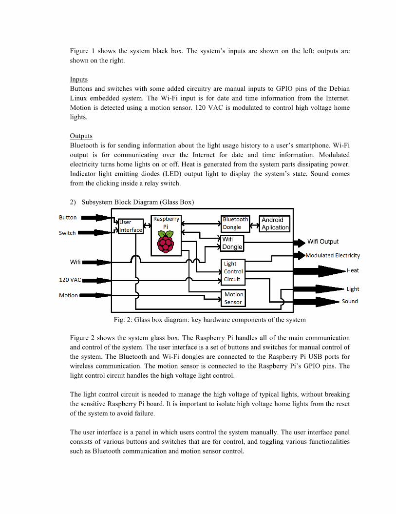
Figure 1 shows the system black box. The system’s inputs are shown on the left; outputs are shown on the right. Inputs Buttons and switches with some added circuitry are manual inputs to GPIO pins of the Debian Linux embedded system. The Wi-Fi input is for date and time information from the Internet. Motion is detected using a motion sensor. 120 VAC is modulated to control high voltage home lights. Outputs Bluetooth is for sending information about the light usage history to a user’s smartphone. Wi-Fi output is for communicating over the Internet for date and time information. Modulated electricity turns home lights on or off. Heat is generated from the system parts dissipating power. Indicator light emitting diodes (LED) output light to display the system’s state. Sound comes from the clicking inside a relay switch. 2) Subsystem Block Diagram (Glass Box)
Fig. 2: Glass box diagram: key hardware components of the system
Figure 2 shows the system glass box. The Raspberry Pi handles all of the main communication and control of the system. The user interface is a set of buttons and switches for manual control of the system. The Bluetooth and Wi-Fi dongles are connected to the Raspberry Pi USB ports for wireless communication. The motion sensor is connected to the Raspberry Pi’s GPIO pins. The light control circuit handles the high voltage light control. The light control circuit is needed to manage the high voltage of typical lights, without breaking the sensitive Raspberry Pi board. It is important to isolate high voltage home lights from the reset of the system to avoid failure. The user interface is a panel in which users control the system manually. The user interface panel consists of various buttons and switches that are for control, and toggling various functionalities such as Bluetooth communication and motion sensor control.

3) System State Diagram
Fig. 3: State Diagram: the 4 main modes of the system
In this document, the words state and mode are used interchangeably. Figure 3 shows the four states of the system. In the off state, lights are always off. In the Manual state, the lights only change as requested. In the semi-automatic state, the system makes recommended changes to the light based off of the recognized pattern, and information from the motion sensor. In the automatic state, the system controls lights to mimic those lights usual usage. A user can change between the four states at any time through the Android application (granted the option is enabled), or via four buttons shown on the panel. The buttons on the user interface panel have indicator LEDs to let the user know what state the system is in. Off In this state the lights are off, and any request to turn the lights on are denied. The user may change to any other mode from the manual buttons, or Bluetooth (granted that it is enabled). The system records when a user attempts to change the light status, or if the mode is changed. Manual The system makes no changes to the light status, unless specified to do so by the user in real time. Control may be through manual control, or smartphone (if enabled). The system records when any changes are made to the lights, or if the mode is changed.

Semi-Automatic The system toggles the light status based on patterns recognized, user preset times, or the motion sensor observations (if enabled). If no motion is detected for 30 minutes, the lights are turned off. The user may change the status of the lights from their smartphone or with the manual controls. The system records when any changes are made to the lights, or if the mode is changed. Automatic All light status toggle requests are denied. The system uses recognized patterns to automatically turn lights on or off at typical times, so that it seems as if someone is home. The mode changing rules as explained in the aforementioned modes, still applies.
B. Design Approach To make an easy to install smart light system, the team decided to make a smart light switch that replaces ordinary light switches. This system does not require any specially designed light bulbs. The faceplate (panel) of the light switch box has four buttons, four indicator LEDs, and three switches. Users may toggle light status, toggle Bluetooth control, toggle motion sensor intervention, or mode of the system through the buttons or switches on the user interface panel. A variety of skills are required for the completion of this senior project. Circuit designing is important for the light control subsystem and the user interface. The system was programmed in Python, C++, Java, XML, and Bash. A smartphone application for Android was developed. Communication over Bluetooth must be implemented. The system gets date and time information from Wi-Fi, which is set up with information from the Android application over Bluetooth. Initially, the team did not have all the skills and knowledge to complete this senior project. Methods of organizing and storing the recorded data must be researched. No team members had any experience in Android application programming. Managing the Wi-Fi settings on the Raspberry Pi from the smartphone was necessary, and was researched; SPOILER ALERT: it was not very hard.
C. Method of Solution
Motion Sensor
Fig. 4: Motion Sensor Pins
The chosen motion sensor for the project is the HC-SR501. It uses a 3.3V Vcc from the Raspberry Pi. When motion is detected, the output is 3.3V until no more motion is detected for at least 6 seconds. A simple input output circuit was built to test the motion sensor. It worked as expected.

Prediction Algorithm An algorithm for pattern recognition and prediction is to be developed for this project. The system records every event change in the lighting system, whether it be from user inputs, or automatic decisions. The system also records the status of the lights every 15 minutes. The system uses this information to work with a user to provide the best light usage experience. The algorithm is based off of the Master Thesis Predicting user behavior using transition probability [1]. This algorithm uses recorded transition between states as data. This information includes things like when state transitions occur, what the previous state was, and what the new state is. This method consists of three stages. The first stage is the initial point distribution for all states. In this stage every state is given points according to how many times they occurred. After the points are given, all state’s point’s are multiplied by a number determined by how similar they are to the current state. The more similar, the higher the multiplier is. After this, the algorithm moves to the second stage. The second stage is where points are redistributed according to the transitions. The first part of this stage is to find all the transitions that happened within a set time interval around the time for the desired prediction. After this, all the found transitions are summed to find out how many times each transition occurred. During this summing, transitions are also weighted so that a transition closer to the desired time is worth more than ones further away. After this is done, points are then redistributed according to the transitions. After all the points are redistributed, the method moves to the final stage: where the prediction is made. In this stage, all the points for the modes where the desired item is are summed. This sum is divided by the total points. If the result of this division is above or equal to a threshold, the prediction is valid otherwise it is invalid. For our system the desired item is the light state and the desired state is on. This solution was tested only in MATLAB simulations. The result was a 60% accuracy in predicting weekly events. Light Control Circuit
Fig. 5: Light control circuit diagram
The light control circuit enables control of high voltage lights from the Raspberry Pi. The light control circuit consists of a high voltage relay switch, a transistor, a flyback protection diode, and a resistor. The chosen flyback diode was the 1N4004. The NPN BJT is a 2N3904. The resistor is 820Ω. A pin output of the Raspberry Pi turns the transistor on or off, which drives the relay switch. The resistor makes sure that a safe amount of current is drawn from the Raspberry Pi, and that an appropriate current is driving the relay switch. The flyback diode prevents high voltage spikes from the relay switch from damaging any other components of the system. The solution was tested with a DC power supply from the lab that acted as 3V from the Raspberry Pi, and the 5V source. A simple desk lamp acted as the home lights. All voltages are within a 10% range of theoretical design calculations, thus the solution worked properly. User Interface Circuit
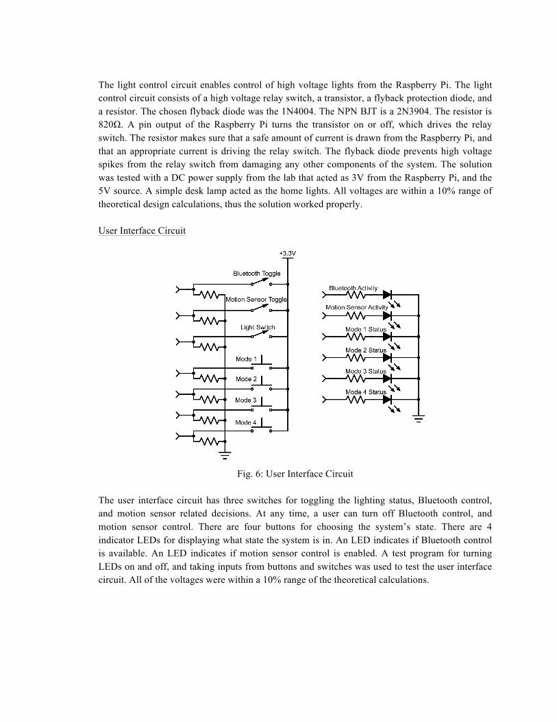
Fig. 6: User Interface Circuit
The user interface circuit has three switches for toggling the lighting status, Bluetooth control, and motion sensor related decisions. At any time, a user can turn off Bluetooth control, and motion sensor control. There are four buttons for choosing the system’s state. There are 4 indicator LEDs for displaying what state the system is in. An LED indicates if Bluetooth control is available. An LED indicates if motion sensor control is enabled. A test program for turning LEDs on and off, and taking inputs from buttons and switches was used to test the user interface circuit. All of the voltages were within a 10% range of the theoretical calculations.
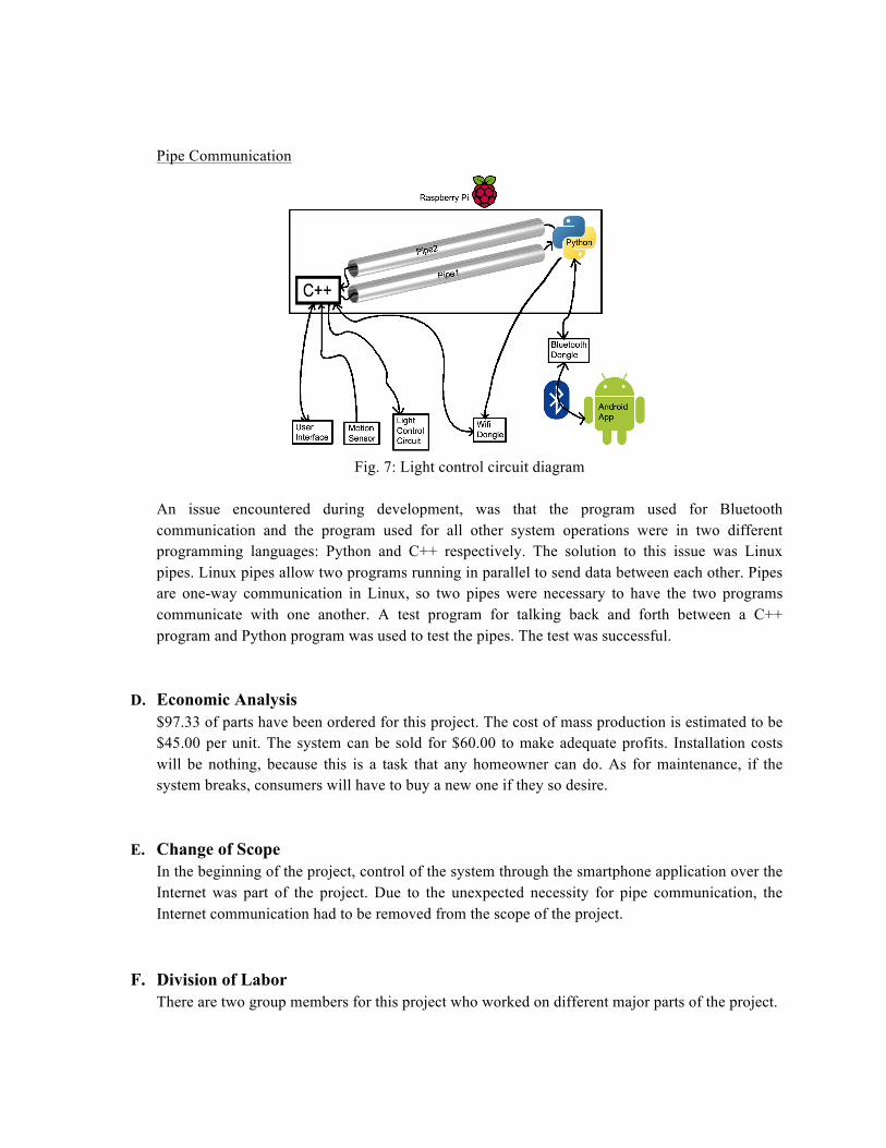
Pipe Communication
Fig. 7: Light control circuit diagram
An issue encountered during development, was that the program used for Bluetooth communication and the program used for all other system operations were in two different programming languages: Python and C++ respectively. The solution to this issue was Linux pipes. Linux pipes allow two programs running in parallel to send data between each other. Pipes are one-way communication in Linux, so two pipes were necessary to have the two programs communicate with one another. A test program for talking back and forth between a C++ program and Python program was used to test the pipes. The test was successful.
D. Economic Analysis
$97.33 of parts have been ordered for this project. The cost of mass production is estimated to be $45.00 per unit. The system can be sold for $60.00 to make adequate profits. Installation costs will be nothing, because this is a task that any homeowner can do. As for maintenance, if the system breaks, consumers will have to buy a new one if they so desire.
E. Change of Scope In the beginning of the project, control of the system through the smartphone application over the Internet was part of the project. Due to the unexpected necessity for pipe communication, the Internet communication had to be removed from the scope of the project.
F. Division of Labor There are two group members for this project who worked on different major parts of the project.

TABLE II. DIVISION OF LABOR FOR THE TWO TEAM MEMBERS
Alex Berian focused on all of the hardware. This includes the light control circuit, and the user interface as shown in fig 2. All non-manual communications was designed for only the Android smartphone application. Alex Berian completed all front end and wireless programming. Dustin McCart focused solely on the back end software. This includes reading/writing to pins on the Raspberry Pi, programming the various modes with or without pattern recognition and storing the saved data.
G. Societal Impact Safety and liability is a huge concern for the smart lighting system project. When consumers install the system, to a light switch box, there is a chance they may shock themselves; a disclaimer or warning is necessary. When dealing with any home appliance that uses high voltage, it is beneficial to have the product certified by Underwriters Laboratories (UL). UL is the standard company that deems devices to be safe for consumer use. The system must be able to withstand an unpredictable user, in order to be safe for consumers. The system is very beneficial for consumers who are looking for home automation. It is common that people are unable to wake up to loud music. Flashing lights may prove to be a more effective morning alarm system for certain individuals. The system turns the lights off when nobody is using them, and someone forgets to shut them off, which saves a lot electricity. With the automatic mode on the system, consumers can create the illusion that they are home, when in fact they are on vacation. This helps prevent burglary.
III. CONCLUSION A. Key Points
This project is a smart light switch with smartphone control over Bluetooth and internet. The system recognizes light usage patterns, and can make predictive changes to the lights based off of these patterns.

B. Specifications The system’s main controller and computer is a Linux embedded system. There is a motion sensor, Bluetooth USB dongle, and Wi-Fi USB dongle for smarter control. Wi-Fi, and Bluetooth control may be disabled with switches. The motion sensor may also be disabled with a switch. The system records every change made by users. Modes are always interchangeable. The system must fit into a 22-cu 1-gang new work wall electrical box. Based off of Predicting user behavior using transition probability, the system recognizes light usage patterns, and uses those patterns to work with the user.
C. Advantages
The smart light system can improve people’s day-to-day lives through alarms, or preset on/off times. The system can save energy by turning off lights that are not in use. Burglary can also be prevented with the automatic lighting mode.
D. Summary There are many components to this project, and it is important to stay organized and know what it is each member must do, and when they must do it. Clearly defining the project is very important, especially for large teams, because it reduces the time in which team members are not doing anything productive.
IV. REFERENCES
[1]R. Heukels, Predicting user behavior using transition probability, 1st ed. Drienerlolaan: University of Twente, 2015.

V. APPENDIX
TABLE III. ORIGINAL GANTT CHART: VISUAL SCHEDULE OF PROJECT TASKS
Fig. 8: Flow Chart: of the main loop
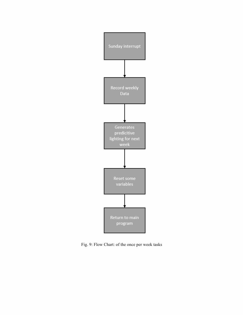
Fig. 9: Flow Chart: of the once per week tasks

Fig. 10: Flow Chart: of the interrupt to occur every 15 minutes