smart gauge pressure transmitters - tek-troltek-bar 3120b is a smart gauge pressure transmitter used...
TRANSCRIPT

Technology Solutions
T AR 3120BEK-B
Instruction Manual
Smart Gauge Pressure Transmitters
Document Number: IM-3120B
www.tek-trol.com

www.tek-trol.com
NOTICERead this manual before working with the product. For personal and system safety, and for optimum product performance, make sure you thoroughly understand the contents before installing, using, or maintaining this product.For technical assistance, contactCustomer Support796 Tek-DriveCrystal Lake, IL 60014USATel: +1 847 857 6076, +1 847 655 7428
© COPYRIGHT Tek-Trol LLC 2019No part of this publication may be copied or distributed, transmitted, transcribed, stored in a retrieval system, or translated into any human or computer language, in any form or by any means, electronic, mechanical, manual, or otherwise, or disclosed to third parties without the express written permission. The information contained in this manual is subject to change without notice.

Table of Contents Table of Contents ................................................................................................................................. 1
1 Safety Instructions ......................................................................................................... 3 1.1 Intended Use .....................................................................................................................3 1.2 Certification .......................................................................................................................3 1.3 Safety Instructions from the Manufacturer .........................................................................3
Disclaimer ................................................................................................................................ 3 Product Liability and Warranty ............................................................................................... 3 Information Concerning the Documentation .......................................................................... 3 Safety Precautions ................................................................................................................... 4
1.4 Packaging, Transportation, and Storage ..............................................................................5 ................................................................................................................................. 5
Transportation......................................................................................................................... 5 Storage .................................................................................................................................... 6
1.5 Nameplate .........................................................................................................................6
2 Product Description ....................................................................................................... 7 2.1 Introduction ......................................................................................................................7 2.2 Measurement Principle ......................................................................................................7 2.3 Specifications .....................................................................................................................8
General Specifications ............................................................................................................. 8 Damping Time ......................................................................................................................... 8 Environmental Conditions ....................................................................................................... 8 Power Supply ........................................................................................................................... 9 Measuring Range Limit for Tek-Bar 3120B.............................................................................. 9
2.4 Dimensional Drawings .......................................................................................................9 2.5 Model Chart..................................................................................................................... 10
3 Installation................................................................................................................... 11 3.1 Selecting the Installation Location .................................................................................... 11 3.2 Installation Procedure ...................................................................................................... 11
Install Pressure Transmitter .................................................................................................. 11 Process Connections ............................................................................................................. 12 Housing Rotation ................................................................................................................... 13 Terminal Side of Transmitter ................................................................................................ 13 LCD Display ............................................................................................................................ 13 Conduit Installation ............................................................................................................... 14
3.3 Mounting Requirements .................................................................................................. 14 Liquid Flow Measurement .................................................................................................... 14 Gas Flow Measurement ........................................................................................................ 15 Steam Flow Measurement .................................................................................................... 15
3.4 Field Adjustment ............................................................................................................. 16 Zero Point Adjustment .......................................................................................................... 16 Full Span Adjustment ............................................................................................................ 16
3.5 Product Usage ................................................................................................................. 16 Pipeline pressure measurement-pressure transmitter ......................................................... 16 Pipeline pressure measurement-differential pressure transmitter ...................................... 16 Steam flow measurement ..................................................................................................... 17

Liquid flow measurement ..................................................................................................... 17 Air flow measurement........................................................................................................... 17 Open container level measurement-single flange level transmitter .................................... 17 Sealed container level measurement-single flange level transmitter .................................. 17
4 Electrical Connections .................................................................................................. 18 4.1 Grounding of Measuring Device ....................................................................................... 18 4.2 Power Supply Specifications and Connection .................................................................... 19 4.3 Cable Protection System .................................................................................................. 20
Standard Protection System .................................................................................................. 20 Explosion-proof Tube Protection System .............................................................................. 21 Connection to the HART Handheld Communicator .............................................................. 21
5 Operation .................................................................................................................... 22 5.1 Local Operation and Display ............................................................................................. 22 5.2 Operation in safe and hazardous area .............................................................................. 22 5.3 Configuration ................................................................................................................... 22
Key Operation ....................................................................................................................... 23 Factory Reset ......................................................................................................................... 23 Factory Reset ......................................................................................................................... 23
5.4 Handheld Communicator ................................................................................................. 27
6 Maintenance ................................................................................................................ 28 6.1 Hardware Maintenance ................................................................................................... 28
Test Terminal ......................................................................................................................... 28 Disassembling the Electronics Housing ................................................................................. 28 External Cleaning ................................................................................................................... 28 Depot Repair ......................................................................................................................... 29 Discard Disposal .................................................................................................................... 29
7 Troubleshooting ........................................................................................................... 30 7.1 Symptoms and Corrective Measures ................................................................................. 30 7.2 Tek-Bar 3120B Smart Gauge Pressure Transmitter LCD Display error codes ........................ 32

1 Safety Instructions
1.1 Intended Use Tek-Bar 3120B is a Smart Gauge Pressure Transmitter used for pressure, flow, level and density measurement of steam and liquids. The manufacturer is not liable for damage caused by improper or non-designated use.
1.2 Certification Tek-Bar 3120B has FM approval (Class I Div. I)
1.3 Safety Instructions from the Manufacturer
Disclaimer The manufacturer will not be held accountable for any damage that happens by using its
product, including, but not limited to direct, indirect, or incidental and consequential
damages.
Any product purchased from the manufacturer is warranted in accordance with the
relevant product documentation and our Terms and Conditions of Sale.
The manufacturer has the right to modify the content of this document, including the
disclaimer, at any time for any reason without prior notice, and will not be answerable in
any way for the possible consequence of such changes.
Product Liability and Warranty The operator shall bear authority for the suitability of the device for the specific
application. The manufacturer accepts no liability for the consequences of misuse by the
operator. Wrong installation or operation of the devices (systems) will cause the warranty
to be void. The respective Terms and Conditions of Sale, which forms the basis for the
sales contract shall also apply.
Information Concerning the Documentation To prevent any injury to the operator and damage to the device it is essential to read the information in this document and read the applicable national standard, and safety instruction. These operating instructions contain all the information that is required in various stages, like product identification, incoming acceptance and storage, to mounting, connection, operation and commissioning through to troubleshooting, maintenance and disposal.

Safety Precautions You must read these instructions carefully prior to installing and commissioning the
device. These instructions are an important part of the product and must be kept for
future reference. Only by observing these instructions, optimum protection of both
personnel and the environment, as well as safe and fault-free operation of the device can
be ensured.
For additional information that are not discussed in this manual, contact the manufacturer.
Warnings and Symbols Used
The following safety symbol marks are used in this operation manual and on the instrument.
WARNING
Indicates a potentially hazardous situation which, if not avoided, could result in death or serious injury.
CAUTION
Indicates a potentially hazardous situation which, if not avoided, may result in minor or moderate injury. It may also be used to alert against unsafe practices.
NOTE
Indicates that operating the hardware or software in this manner may damage it or lead to system failure.
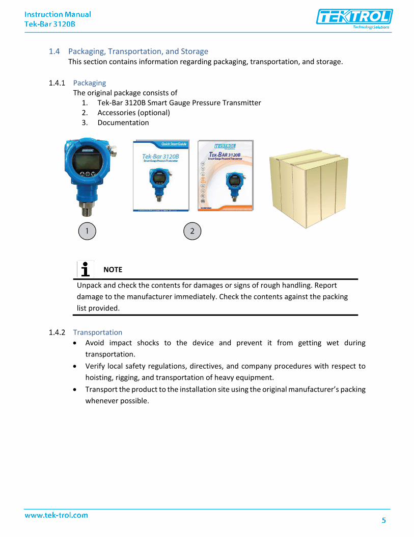
1.4 Packaging, Transportation, and Storage This section contains information regarding packaging, transportation, and storage.
Packaging The original package consists of
1. Tek-Bar 3120B Smart Gauge Pressure Transmitter2. Accessories (optional)3. Documentation
NOTE
Unpack and check the contents for damages or signs of rough handling. Report
damage to the manufacturer immediately. Check the contents against the packing
list provided.
Transportation
• Avoid impact shocks to the device and prevent it from getting wet during
transportation.
• Verify local safety regulations, directives, and company procedures with respect to
hoisting, rigging, and transportation of heavy equipment.
• Transport the product to the installation site using the original manufacturer’s packing
whenever possible.

Storage If this product is to be stored for a long period of time before installation, take the following precautions:
• Store your product in the manufacturer’s original packing used for shipping.
• Storage location should conform to the following requirements:o Free from rain and watero Free from vibration and impact shocko At room temperature with minimal temperature and humidity variation
• Before storing a used flowmeter remove any fluid from the flowmeter linecompletely. Properties of the instrument can change when stored outdoors.
1.5 Nameplate The nameplate lists the order number and other important information, such as design
details and technical data.
NOTE
Check the device nameplate to ensure that the device is delivered according to your order. Check for the correct supply voltage printed on the nameplate.

2 Product Description This section covers the reference and specification data, as well as ordering information.
2.1 Introduction Tek-Bar 3120B single crystal silicon pressure transmitter utilizes world’s leading mono crystal silicon pressure sensor technology and outstanding encapsulation technology. It can handle the most rigorous industrial applications and it can cope up with extreme chemical, mechanical and electrical working conditions. Highly accurate and reliable measurement of level, density and pressure of liquid, gases or steam is possible with Tek-Bar 3120B. The performance accuracy is up to 0.075% of URL. This high-performance pressure transmitter meticulously designed by Tek-Trol supports HART communication protocol and IP66 waterproof protection. It is well equipped with several features that facilitate easy installation, start-up and minimum maintenance.
2.2 Measurement Principle The Tek-Bar 3120B works on the principle of mono silicon technology. The pressure sensor
of the transmitter is located on the top of the metal body, away from the service fluid. This
enables mechanical and thermal isolation of the sensor from the fluid in service.
When pressure is applied on the diaphragm and the silicon piezoelectric sensor, they
become stressed and undergo a change in voltage resistance. This change in resistance is
directly proportional to the applied pressure, which is transferred to the transmitter body
using lead wires.
Built on semiconductor technology, the resistance change (piezoelectric effect) is notably higher than exhibited in standard strain gauges. Therefore, the sensitivity of mono-crystalline sensors is higher than the sensitivity of most other types.

2.3 Specifications
General Specifications
Parameter Description
Pressure Type Gauge Pressure
Accuracy ±0.075% F.S.
Diaphragm Materials Hastelloy C
Ranges 5.8 psig to 5800 psig
Stability ±0.2 % URL/5 year
Process Connection ±0.075% F.S.
Wetted material 316LLS
Working Humidity 5 to 100%
Output Signal Two wire 4to 20mA with Hart®
Mounting Position Effect Apply to any position. Max value lower than 1.6 w.c.
(400 Pa) can be corrected by zero clearing function
Insulation Resistance ≥20 M Ω at 100 VDC
Process Connection ¼" NPT Female
Approvals General purpose NEMA 4X or IP66
Weight (excluding Option Items)
3.43 lb (1.55kg)
Testing Standard IEC60770
Damping Time
Parameter Description
Damping time 0-100s adjustable
Response time ≤0.2 s
Start-up after power off ≤6 s
Environmental Conditions
Parameter Description
Working temperature -40 °F to 185 °F (-40 °C to 85 °C),
Storage temperature -40 °F to 230 °F (-40 °C to 110 °C)
Media temperature Silicon oil filling: -40 °F to 248 °F (-40 °C to 120 °C)
Working humidity 5-100% RH at 104 °F
Protection class IP66

Power Supply
Parameter Description
Power supply 10.5-55 VDC (Hart: 16.5-55 VDC)
Load resistance 0-2119 Ω for working condition, 250- 600 Ω for HART protocol
Transmission distance
<3281ft
Power consumption ≤500 mW at 24 VDC, 20.8 mA
Measuring Range Limit for Tek-Bar 3120B
Nominal Value
Smallest Calibrated Span
Lower Range Limit (LRL)
Upper Range Limit (URL)
Overload Limit
5.8 psi 8 in.WC -14.5 psi 5.8 psi 145 psig
36 psi 2 psi -14.5 psi 36 psi 580 psig
145 psi 7.25 psi -14.5 psi 145 psi 870 psig
435 psi 22.25 psi -14.5 psi 435 psi 2175 psig
1450 psi 72.5 psi -14.5 psi 1450 psi 2900 psig
5800 psi 725 psi -14.5 psi 5800 psi 11600 psig
2.4 Dimensional Drawings

2.5 Model Chart
Example Tek-Bar 3120B-G 3 WP 1 HC 1 BA Tek-Bar 3120B-G-3-WP-1-HC-1-BA
Series Tek-Bar 3120B-G Smart Gauge Pressure Transmitter
1 0 to 5.8 psig (40:1 Turndown, Adj. Range: -14.5 to 5.8 psig)
2 0 to 36 psig (40:1 Turndown, Adj. Range: -14.5 to 36 psig)
3 0 to 145 psig (40:1 Turndown, Adj. Range: -14.5 to 145 psig)
Range Options 4 0 to 435 psig (40:1 Turndown, Adj. Range: -14.5 to 435 psig)
5 0 to 1450 psig (40:1 Turndown, Adj. Range: -14.5 to 1450 psig)
6 0 to 5800 psig ( 8:1 Turndown, Adj. Range: -14.5 to 5800 psig)
Approval Rating
WP
AT
General Purpose NEMA 4X/IP66
ATEX
Process Connections 1
X
½" NPT Male
Diaphragm Seal
Diaphragm Material HC Hastelloy C
Electrical Connections 1 ½" NPT Female
Options
CC
FC
BA
TAG
Custom Calibration with 5 point Calibration Certificate Factory
Configuration, No Certificate
Stainless Steel Bracket (Angle type) with SST Bolts
Custom Etching of the Name Plate (Must specify on P.O.)

3 Installation This section covers instructions on installation and commissioning. Installation of the device
must be carried out by trained, qualified specialists authorized to perform such works.
CAUTION
• When removing the instrument from hazardous processes, avoid direct contact
with the fluid and the meter
• All installation must comply with local installation requirements and local
electrical code
3.1 Selecting the Installation Location Prior to product installation, check the model, specifications and installation location for the transmitter. The transmitter is designed to withstand severe environmental conditions. However, follow the enlisted precautions while selecting the installation site to ensure stable and accurate operation for years.
• Ambient TemperatureAvoid locations subjected to significant temperature gradient or wide temperaturevariations. If transmitter is exposed to radiant heat from plant’s equipment, thenproviding adequate thermal isolation and/or ventilation is desirable.
• Ambient AtmosphereAvoid corrosive atmosphere while installing the transmitter. If it must be installed in acorrosive atmosphere, then provide adequate ventilation and take the necessarymeasures to prevent intrusion or stagnation of rain water in conduits.
• Shock and VibrationAlthough the transmitter is designed to withstand shock and vibrations, it isrecommended to select an installation site with minimum shock and vibration to avoiddevice damage and improve measurement accuracy.
3.2 Installation Procedure This section includes the information regarding installation of the transmitter for safe and precise functioning. It provides the procedure and instruction for mounting, transmitter functions, and installation for specific applications.
Install Pressure Transmitter Direct installation or mounting bracket installation may be used depending on the application and installation site requirement. Various mounting scenarios are illustrated in sections below.

Process Connections
3.2.2.1 Straight Thread Connection
Picture 1 Picture 2
Picture 1: Ensure that the seal of head face gasket is effective by keeping the length of the pressure transmitter thread longer than the depth of the thread. Picture 2: Ensure that the seal of root gasket is effective by maintaining the length of the pressure transmitter thread shorter than the depth of the thread.
3.2.2.2 Taper Thread Connection
Use tapered thread connections to make better seals. Sealing with Teflon tape or sealant glue results in strong and leak resistant connections.
3.2.2.3 Flange Connection
Choose gasket according to the properties of the process medium and the temperature range. Pay attention to the bolt balance lock
3.2.2.4 Clamp Connection

Choose gaskets that meet specified standards to avoid excessive clamp locking and squeezing gasket. Excessive locking of clamp may damage the sensing diaphragm and cause measuring error.
NOTE
Engage process connection with a minimum of 7 thread connections and tighten the housing rotation set screw to prevent it from rotating
Housing Rotation To ensure the visibility of LCD display
• Loosen the housing screw
• Rotate housing to the desired angle up to 360o
• Re-tighten the housing screw
Terminal Side of Transmitter Mount the transmitter in such a way that the terminal side is easily accessible to the operator.
LCD Display Display module is used in field adjustment for parameter settings and site configuration before starting the measurement process. The local 5-digit LCD displays important parameters, which can be directly monitored at the measuring point. It enables the operator to configure the device using the function matrix.
Display can be rotated 355°

Conduit Installation Improper sealing of connections may damage the transmitter due to excess moisture accumulation. Mount the transmitter with electrical housing positioned downward so that the excess of moisture is condensed and drained out from the casing. Secondly, install wiring with a drip loop and ensure the bottom of the drip loop is mounted lower than the conduit connections or the transmitter housing to avoid moisture accumulation in the housing.
NOTE
Conduit thread must be engaged with a minimum of 5 thread connections
3.3 Mounting Requirements Impulse piping configuration and transmitter position depends on specific measurement conditions. Follow the procedure below while installing transmitter for liquid, gases or steam processes.
Liquid Flow Measurement
• Place the taps to the side of the line/pipe to prevent residue deposits on thetransmitter process isolators
• Mount the transmitter beside or below the taps so gases can vent into the processline
• Mount drain/vent the valve upward to allow gases to vent
Flow

Gas Flow Measurement
• Place the taps in the top or side of the line
• Mount the transmitter beside or above the taps so liquid will drain into the processline
Steam Flow Measurement
• Place taps to the side of the line
• Mount the transmitter below the taps to ensure that the impulse piping stays filledwith condensate
• In steam service above 250°F (121°C), fill impulse lines with water to prevent thedirect steam contact with the transmitter and to ensure accurate measurement atstart-up
NOTE
For steam or other higher temperature processes, ensure that the temperature at the process connection does not exceed the transmitter’s process temperature limits.
Flow
Flow

3.4 Field Adjustment Perform field adjustments only after installing the transmitter at its final work location otherwise the set parameters may drift due to jerks while transporting or handling.
Zero Point Adjustment
• For sensor zero trim, ensure that the vessel is empty and there is no input mediumpressure on the diaphragm. The vessel should be applied a normal atmosphericpressure. If applying external pressure to the transmitter make sure that the displayis sufficiently stabilized (after approximately 10 to 15 seconds), before initiating anytrim function.
• There are 3 ways of making input pressure “Zero”. Apply a “Zero” pressure source (mandatory for absolute pressure models) Apply equal pressure on both HP and LP ports (DP models only) Open equalizing valve of manifolds installed and venting to atmospheric
pressure (applicable for Gauge & DP type models only)
• Sensor zero trim can be performed using an external HHC (Handheld calibrator), PCor PDA configurator, and/or using Zero/Span local push buttons provided on thetransmitter.
• Using local push buttons set PV=0, refer to section 5.2.1 of this manual for detailedinstructions. If using an external HHT or HART® PC configurator, refer to the usermanual supplied by the third-party supplier.
Full Span Adjustment
• For full span adjustment, ensure that the vessel is filled with process medium to themaximum level.
• Maintain static pressure value within the minimum and maximum pressure range
• Using local push buttons set output for lower and upper limit of the full scale i.e.4mA and 20mA, refer to section 5.2 of this manual for detailed key operations.
The device is now ready for the real-time process measurement.
3.5 Product Usage
Pipeline pressure measurement-pressure transmitter For high temperature steam measurements, pre-inject more than half-tube cooling water in the condenser. Once the steam pipes are stable, gradually open the shut-off valve to start measurement.
Pipeline pressure measurement-differential pressure transmitter For high temperature steam measurement in a pipeline by differential pressure transmitter, pre-inject cooling water into the guided pipe. Once the steam pipes are stable, slowly open the shut-off valve and start measuring.

Differential pressure transmitters are commonly used for micro pressure measurement of hydrostatic pressures such as filter and equipment leakage tests for improving accuracy.
Steam flow measurement For steam flow measurement, up-tilt the guiding pressure tube by 45°. Ensure that transmitter installation location is at lower level than that of the process pipeline. Pre-inject cooling liquid into the guiding pressure tube. Slowly open the shut-off valve to start measurement. Periodically open the drain vent to clear the residual steam from guided pipeline to improve the measurement accuracy.
Liquid flow measurement For liquid flow measurement, tilt down the guiding pressure tube by 45°. Ensure that transmitter installation location is at lower level than that of the process pipeline. Pre-inject cooling liquid into the guiding pressure tube. Slowly open the shut-off valve to start measurement. Periodically open the drain vent to clear the residual liquid, which will improve the measurement accuracy.
Air flow measurement For liquid flow measurement, up-tilt the guiding pressure tube by 45°. Ensure that transmitter installation location is at lower level than that of the process pipeline. Pre-inject cooling liquid into the guiding pressure tube. Slowly open the shut-off valve to start measurement. Periodically open the drain vent to clear the residual gas from the guiding pressure tube, which will improve the measurement accuracy.
Open container level measurement-single flange level transmitter Verify the process medium compatibility in case of open container level measurement. For accurate measurement, install the transmitter at a location where liquid level and temperature fluctuations are minimal.
Sealed container level measurement-single flange level transmitter Use a single flange diaphragm system for sealed container level measurement. Increase the isolation tank and multiple shut-off valves. Periodically open the drain/vent valve to clear off the residual gas and liquid in the guiding pressure tube for higher accuracy.

4 Electrical Connections This section covers the all electrical connection requirement. Electrical connection of the
device must be carried out by trained, qualified specialists authorized to perform such work
by the installation site.
WARNING
• Connect all electrical cables when the power is switched off. If the device does
not have switch-off elements, then, overcurrent protection devices, lightning
protection and/or energy isolating devices must be provided by the customer.
• The device must be grounded to a spot in accordance with regulations to
protect personnel against electric shocks.
NOTE
• When using the measuring device in hazardous areas, installation must
comply with the corresponding national standards and regulations and the
Safety Instructions or Installation or Control Drawings.
4.1 Grounding of Measuring Device • Ensure proper grounding at control cabinet and pressure transmitter.
• Ground terminals are provided on the either sides (inside and outside) of the terminalbox. Either one of these terminals may be used for grounding the transmitter.
• Use shielded twisted pair cable to avoid ground loops.
• Use internal ground terminals for direct grounding.

4.2 Power Supply Specifications and Connection Use independent linear direct current power supply for pressure transmitter. Large resistive load results in high pressure drop. Therefore, it is recommended to consider the resistance across the signal cable, display meter and other equipment to ensure sufficient voltage is provided to the pressure transmitter for its normal operation.
Standard current signal output: 12-30VDC, Current signal output with HART: 16.5-55VDC, Current signal output with intrinsic safety: 12-30VDC, Modbus-RTU/RS485 signal output: 5VDC/9-30VDC, 0.5-4.5VDC Voltage signal output: 5 VDC/6-15VDC.
Remove the housing cover on terminal compartment side. Do not remove the cover in explosive atmospheres when the circuit is live.
Label Two Wires Three Wires Four Wires
+ Power + Power + Power +
- Power - Power - Power -
A Signal + Signal +
B Signal -
Power supply connections:
• Connect power supply ‘+’ terminal to transmitter ‘+’ terminal.
• Connect signal ‘+’ terminal to transmitter ‘-’ terminal.
• Connect signal ‘-’ terminal to power supply ‘-’ terminal.
• Do not connect power signal wiring to the test terminals as it could damage the testdiode.

Power Supply Connections
4.3 Cable Protection System Apply following cable protection measures to protect the connecting cables from various factors that affect negatively on the cable lifetime.
Standard Protection System
• To avoid liquid flowing along with the cable into the terminal box, configure aU-shaped ring between pull box and pressure transmitter as shown in thefigure below.
• Ensure that the level of U-shaped bottom is maintained below the pressuretransmitter.
• Use sufficiently long cable considering the maintenance and repair factors.

Explosion-proof Tube Protection System
• If the transmitter is situated in dangerous area, use a high quality metallic explosion-proof tube as a casing for the cable connecting the transmitter to the terminal box.
Connection to the HART Handheld Communicator A loop resistance for HART Communicator is between 250Ω and 550Ω. Transmitter operates on 11.9 –45 VDC. Figure below illustrates the connection details for HHT communicator.

5 Operation This section covers operation techniques and guidelines along with the configuration and calibration.
NOTE
Calibrate the instrument according the instructions given in this section, otherwise it could lead to measurement error.
5.1 Local Operation and Display Tek-Bar 3120B is available with the optional LCD display. The local display enables user to read important parameters directly at the measuring point and configure the device using the function matrix. The display indicates output and diagnostic messages. It features a two-line display with 5-digit. The first line displays measured value and the second line displays the engineering units. If LCD display is not available, then use HART for communication (Refer section 5.4).
5.2 Operation in safe and hazardous area The internal and external buttons are provided for operation in safe and hazardous areas respectively.
• While operating in safe area, open the front cover and use internal buttons.
• While operating in hazardous area, slide the nameplate located at the upper side ofthe transmitter and use the external buttons.
External buttons for operation in hazardous area
5.3 Configuration This section provides detailed information of initial setup required for transmitter functioning. The device consists of 3 operation key: S, Z and M which are used to set parameters and perform various operations. The primary function of each key is mentioned as below.

Z: Enter the setting options S: Modify the parameter value M: Confirm the set value and enter the next menu The same keys are used in combination to perform several advanced functions.
Key Operation Consider the factory setting for pressure measurement is set as follows: Pressure range: -10 to 100 kPa; Output current display unit: mA For performing zero-point adjustment and full span pressure adjustment follow the instructions and display screenshots given in the flow diagram below.
Factory Reset Achieving the original factory settings at any point of time after the installation of the transmitter is possible by either of the following methods.
Factory Reset Refer the following flow diagram to configure various parameter. Use parameter table to know the possible range of values and units.


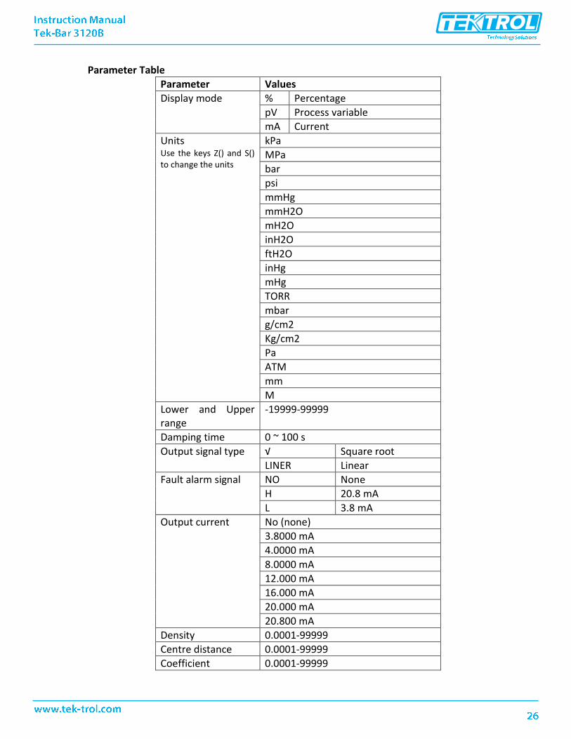
Parameter Table
Parameter Values
Display mode % Percentage
pV Process variable
mA Current
Units Use the keys Z() and S() to change the units
kPa
MPa
bar
psi
mmHg
mmH2O
mH2O
inH2O
ftH2O
inHg
mHg
TORR
mbar
g/cm2
Kg/cm2
Pa
ATM
mm
M
Lower and Upper range
-19999-99999
Damping time 0 ~ 100 s
Output signal type √ Square root
LINER Linear
Fault alarm signal NO None
H 20.8 mA
L 3.8 mA
Output current No (none)
3.8000 mA
4.0000 mA
8.0000 mA
12.000 mA
16.000 mA
20.000 mA
20.800 mA
Density 0.0001-99999
Centre distance 0.0001-99999
Coefficient 0.0001-99999

Cutting value 0-99.999
Pressure type GAUGE Gauge, differential
ABSOLUTE Absolute pressure
5.4 Handheld Communicator If custom display is not available, then configure transmitter parameter using communicator. Decimal point position, Upper range value, Lower range value, Engineering units are configured. See the below flow chart.

6 Maintenance This section covers maintenance techniques and guidelines.
WARNING
Explosion can result into a serious injury or death.
• Do not remove the transmitter cover in explosive environments when thecircuit is live.
• After disconnecting power wait for a minute to allow the circuit and enclosureto cool down before opening.
• Avoid direct contact with the leads and terminals. High voltage on leads cancause electrical shock.
• Ensure that the transmitter casings are sealed when the assembly is inoperating condition.
• Only trained and qualified personnel may undertake start-up and maintenanceactivities.
6.1 Hardware Maintenance Perform maintenance task at regular intervals. Set the maintenance schedule in advance and maintain a logbook to note maintenance activity details. Maintenance schedule depends on the system, installation conditions, working medium and rigorousness of the operation. Consider the system downtime when maintenance cycle is running. Ensure that it does not affect the system performance.
Maintenance majorly involves sensor cleaning and verifying connections.
Test Terminal Test Terminal is marked as TEST on the terminal block. Connect TEST and negative terminal to the test terminal. Ensure that the voltage across the receptacles is kept below the diode threshold voltage so that no current passes through the diode. Make sure that the resistance of the test connection does not exceed 10 ohms while connecting an indicating meter or while taking the test readings. Note that a resistance of 30 ohms can cause an error of approximately 10% of actual value.
Disassembling the Electronics Housing The transmitter assembly comes in dual-compartment housing; one contains the electronic module, and the other contains all wiring terminals and the communication receptacles. The separate compartment of wiring terminals ensures hassle free handling while running a routine maintenance cycle.
External Cleaning
• Use washing agent that will not damage the instruments.
• Protect the pressure sensing diaphragm from mechanical damage caused by sharpobjects or external pressure.

• Mechanical cleaning of the diaphragm is strictly prohibited.
• Do not point the nozzles to the diaphragm when cleaning by pressure washer.
Depot Repair Execute following steps before sending the device for depot repair:
• Disconnect the transmitter carefully. Preserve all accessories and cables forreassembling.
• Remove the harmful residues such as inflammable, poisonous, cancer genic andradioactive substances.
• Repack the device in original packaging material provided at the time of deliveryand send for repair.
Discard Disposal It is recommended to pass the instrument to specialized recycling companies rather than local recycling points.

7 Troubleshooting This section provides troubleshooting techniques for most common operating problems.
When device malfunction is suspected despite the absence of any diagnostic messages on the HHT, inspect following points.
• If measurement signal appears irregular, check whether the process pressure iswithin the working range, or the abnormality lies in the measuring system,installation environment or pressure transmitter. Once diagnosed takecorresponding measures.
• If no signal output or unchanged output signal on corresponding process pressurechanges is observed, then check the power supply polarity, open or short circuit.Check the parameters like voltage, power and load resistance meet the normalworking requirements. Also, ensure there is no leakage or pressure-impulse lineblockage and shut-off valve is closed.
• If the output signal is large or outside the normal range, check whether the supplyvoltage, power consumption, and load resistance meet the normal workingrequirements of pressure transmitters. Verify measuring range settings and adjustthe device calibration. Also, ensure there is no leakage, pressure-impulse lineblockage or rapid temperature fluctuations in the installation and shut-off valve isclosed.
7.1 Symptoms and Corrective Measures Refer to the table below to verify whether the transmitter hardware and process connections are in good working condition:
Symptom Potential Source Corrective Action
No communication between the Transmitter and HART communicator
Loop Wiring Check for a minimum of 250 ohms resistance between the power supply and HHT.
Check for an adequate voltage to the transmitter. The transmitter always requires 11.9 to 45 VDC.
Check for intermittent shorts, open circuits, and multiple grounds
High Output Sensor Input Failure Connect HHT and enter the Transmitter test mode to isolate a sensor failure.
Loop Wiring Check for dirty or defective terminals, interconnecting pins, or receptacles.

Power Supply Check the output voltage of the power supply at the transmitter terminals. It should be 11.9 to 45 VDC in spite of loop scale
Electronics Module Connect HHT and enter the Transmitter test mode to isolate module failure. Check the sensor limits to ensure calibration adjustments are within the sensor range.
Erratic Output Loop Wiring Check the output voltage of the power supply at the transmitter terminals. It should be 11.9 to 45 VDC.
Check for intermittent shorts, open circuits, and multiple grounds.
Check for proper polarity at the signal terminals.
In case measuring electric current while digital communication, output appear around +-0.013mA
Electronics Module Connect HHT and enter the transmitter test mode to isolate an electronics mode failure.
Low Output or No Output
Sensor Element Connect HHT and enter the Transmitter test mode to isolate the sensor failure.
Check the PV to see if it is out of range.
Loop Wiring Check for adequate voltage to the transmitter. The transmitter always requires 11.9 to 45 VDC.
Check for intermittent shorts, open circuits, and multiple grounds.
Check polarity of signal terminal
Check the loop impedance.
Electronics Module Connect HHT and check the sensor limits to ensure calibration adjustments are within the sensor range.

7.2 Tek-Bar 3120B Smart Gauge Pressure Transmitter LCD Display error codes
Message Description
ADJ-U Out of Zero setting value when Zero Adj function using button (upper side)
ADJ-L Out of Zero setting value when Zero Adj function using button (lower side)
ZERO Initial message in using the Zero button
SPAN Initial message in using the Span button
BT-ERR Button Input Sequence Error
P-LOCK Button Input Error when Protect Locked
ZT-ERR Setting Limit (10%) Error when in Zero Trim
-TR- Zero Trim Complete
ZR-ERR Setting Limit Error when executing the Zero button function
-TR- Zero Trim Complete
ZR-ERR Setting Limit Error when executing the Zero button function
SP-ERR Setting Limit Error when executing the Span button function
-ZR- Zero button function Complete
-SP- Span button function Complete
-ZA- Zero Adjustment done
-DONE- Setting Done using button
RNGOVR Setting Limit error when executing other setting function
LCD_OV Over figure values for LCD
SCD-ER Sensor Code Error
F-RST Flash Setting Data Rese
F-LOCK While Flash Setting Data Reset, Protect Locked
F-FAIL Flash Setting Data Reset Failure
-FR- Flash Reset Done
A-RST Analog EEPROM Initializing Start
A-STOR Analog EEPROM Whole Write
A-FAIL Analog EEPROM Whole Write Failure

TEKM
ATIO
N L
LC re
serv
es th
e rig
ht to
cha
nge
the
desi
gns
and/
or m
ater
ials
of i
ts p
rodu
cts
with
out n
otic
e. T
he c
onte
nts
of th
is p
ublic
atio
n ar
e th
e pr
oper
tyof
TEK
MAT
ION
and
can
not b
e re
prod
uced
by
any
othe
r par
ty w
ithou
t writ
ten
perm
issi
on. A
ll rig
hts
rese
rved
. Cop
yrig
ht ©
201
6 TE
KMAT
ION
LLC
TEKM
ATIO
N L
LCD
OC#
TEK/
MR/
MN
L/IM
-312
0C/0
119/
A
Tek-Trol LLC
www.tek-trol.com
Flow | Level | Temperature | Pressure | Valves | Analyzers | Accessories | TekValSys
796 Tek Drive Crystal Lake, IL 60014 USATel.: +1 847 857 6076 , +1 847 655 7428 Fax: +1 847 655 6147
Email: [email protected]
Tek-Trol is a fully owned subsidiary of TEKMATION LLC. We oer our customers a comprehensive range of products and solutionsfor process, power and oil & gas industries. Tek-Trol provides process measurement and control products for Flow, Level,
Temperature & Pressure Measurement, Control Valves & Analyzer systems. We are present in 15 locations globally and are knownfor our knowledge, innovative solutions, reliable products and global presence.