smart control in vibrations of structures - strona główna · smart control in vibrations of...
TRANSCRIPT


Smart Control in Vibrations of Structures
Smart control in vibrations of structures
Bartłomiej Dyniewicz1, Jacek M. Bajkowski2, and Czesław I. Bajer1
Abstract
A semi-active control of structural vibrations is presented as an efficient method of damping. We consider structuressubjected to a load applied in stationary points or to a moving load. We claim that the periodically switched magnetorheologicalactuators, controlled dampers, or elastic envelopes filled with granular materials subjected to controlled underpressure, give amore efficient vibration reduction than a permanently activated ones. In our work we show the efficiency of such a controlstrategy applied to a beams under moving inertial load, cantilevers and rotating shaft. The mathematical analysis allowed usto propose the particular control strategy. The finite element simulation, together with the solution for the control problem,proved that the damping devices should act only for a short period of each cycle of vibration. The control function depends onthe type of the structure, excitation and the type of vibrations. The efficiency of the concept was proved in the experimentaltests. The considered structures exhibit the reduction of amplitudes at the range 10–40% in the periodically controlled case, incomparison to the constant damping.
I. INTRODUCTION
Nowadays adaptive techniques can improve several operational parameters of the vibrating structures. First, we can
decrease the amplitudes of displacements or accelerations in the sensitive points of the system. This can increase the life
time of the structural elements, decrease the fatigue and noise and prevent form transmitting the vibrations from the source
to environment. As an example we can give the advanced anti-seismic technologies. Second, by taking advantage of the
adaptive technologies and real time control we can increase the load carrying capacity of the structures, for example the
bridge spans. The load carried by bridges grows and the permissible speed of vehicles increases as well. The strengthening
of the bridge structures can be performed dynamically with the additional supports controlled semi-actively. Third, stiffening
of the guideways can improve the precision in robotics and mechatronics.
The vibration attenuation can be performed in a several ways. The simplest one is the passive damping treatment.
Unfortunately, this method is usually not sufficiently effective, as we lack the possibility of adjusting the system parameters
to varoius excitations. The second possibility is the active way. The used actuators require constant energy supply and can
apply forces in a prescribed manner. The fundamental disadvantage is the admission of the control out of the phase, which can
lead to damaging the structure. The energy consumption also plays an important role. The third approach is the semi-active
control, that combines advantages of both of the previous types of the control. It is performed by the controlled dampers
or frictional elements, that temporarily change the dynamic properties of the structures and allow the phase trajectory to be
shifted towards the curve of a lower energy on the phase plane. The magnetorheological or electrorheological fluids can be
successfully used in the control devices. The advantage of the semi-active approach is evident when we consider the energy
consumed by the damping devices. The semi-active control of the structural vibrations is considered as the best and most
perspective method of damping.
The literature background on the issues related to the topic concerned in this paper is very rich. We will focus on the
chosen technical problem, which is the increase of the intensity of the damping in vibrating dynamic systems. The influence
of the parametric control on vibrations is well known from academic textbooks. The control strategy is also elaborated in
the case of the fundamental systems. Unfortunately, the real structures rarely correspond to their theoretical or numerical
models, especially control devices like actuators, dampers, valves, etc. do not act perfectly as their models tend to suggest.
Experimental verification always confirms limited efficiency of each of the approach. The direct control theory and the theory
of the inverse problems has stimulated the development of health monitoring of structures: identification of the dynamic
load [1] and simultaneous identification of the load and any damage caused to a structure [2].
The problem of reducing beam vibrations using active control methods is also widely considered in [3]. The analysis
in the frequency domain allowed the authors to reduce the extreme amplitudes. The actively controlled string system was
considered in [4]. A good example of the control of vibrations under a load is described in [5], which presented a method
for computing the response induced by a load traveling over a 1D elastic continuum supported by a set of semi-active
viscous dampers. The adaptive open loop control strategy was proposed. The damping functions were taken to be piecewise
constant. The control strategy was suboptimal, but it outperformed the passive case. The numerical results were presented
for the cases of the string and the Bernoulli–Euler beam. In [6] two elastic beams were coupled by a set of the controlled
*This work was supported by the National Centre for Research and Development (NCBiR)1B. Dyniewicz is with Institute of Fundamental Technological Research, Polish Academy of Sciences, Pawinskiego 5b, 02-106 Warsaw, Poland
[email protected]. M. Bajkowski is with The Faculty of Automotive and Construction Machinery Engineering, Warsaw University of Technology, Narbutta 84, 02-524
Warsaw, Poland [email protected]. I. Bajer is with Institute of Fundamental Technological Research, Polish Academy of Sciences, Pawinskiego 5b, 02-106 Warsaw, Poland
2227

dampers. The relative velocity of the spans provided an opportunity for the efficient control by the means of the adaptive
suspension. As a result, bang-bang type of control was taken into account. The controlled system outperformed the passive
solutions over a wide range of considered conditions. Other interesting results concerning the structural control are presented
in [7], [8], [9].
In the paper we consider three types of structures subjected to a various load applied in stationary points or a moving load.
We claim that the periodically switched magnetorheological actuators, controlled dampers, or granular materials compacted
with underpressure, result in a more efficient vibration reduction than a permanently acting ones. In the work we show the
efficiency of such a control applied to the rotating shaft, beams under moving massless and inertial load, and cantilever beams.
The mathematical analysis allowed us to propose the particular control strategy. The finite element simulation together with
the solution of the control problem proved that the dampers should act only in a short period of the highest displacements
of the structure. The same was proven in the experimental tests. We exhibited the amplitude reduction at the range 10-40%
of the displacements over those with a constant control with maximum power, depending on the type of the formulated
mechanical problem.
The presented extensive research is addressed to both, researchers and practicing engineers.
II. UNCONVENTIONAL MATERIALS IN DAMPING OF VIBRATIONS
There are numerous techniques that are more efficient in vibration attenuation than the simple, passive material damping.
Depending on the rate of dissipation we can enhance the efficiency of the passive methods with the parametric modification of
the governing differential equations. In such a way various physical quantities like velocity or acceleration can be decreased
significantly [10], [11]. The composite sandwich sheets with introduced layers of smart materials like piezo-actuators,
magneto- and electrorheological fluids or other controllable elastomers, are the most popular semi-active, modern solutions
for the attenuation of the unwanted structural vibration. We also investigate the possibility to use the controlled granular
materials as a light weight, low cost, interesting alternative for the classical damping solutions dedicated for the layered
structures.
A. Magnetorheological fluids and MR dampers
Since the discovery of the magnetorheological (MR) effect by Rabinow in 1948 [12], [13], these materials have been
developed into a family with MR fluids, foams, greases, gels and elastomers. Generally, the MR materials are ferromagnetic,
micrometer-sized carbonyl iron particles suspended in the carrier medium. The most common of this group are the MR fluids,
with ferrous particles suspended in a silicone oil. When exposed to a magnetic field, the particles polarize along the magnetic
flux lines in a chain-like structures, and the fluid changes its state from the free-flowing to a semi-solid which is called the
active one. The yield stress and apparent viscosity of the fluid increases as a consequence of the particles rearrangement. The
transition between the states is a fully reversible process and takes only several milliseconds to complete. The possibility
of controlling the yield strength of the MR fluids by the means of the magnetic field, predestines them to be utilized in
devices like dashpots, rotary brakes, clutches, bearings, stabilizers, polishing systems and other. The mechanical construction
of the MR device and the properties of the fluid itself result in a controllable dynamic response of the system. For example
magnetorheological fluid dampers have a semi-controllable damping force output that is dependent on the current input to the
damper, as well as the relative velocity. They have been been successfully used in the automotive industry in an intelligent car
suspensions, for the stabilization of high buildings vulnerable to seismic activity or semi-active control of bridge structures.
Despite the fact of growing number of practical applications, producing high-quality MR fluid with desired characteristic is
still hard to achieve. Different types of commercially available fluids share similar limitations like susceptibility to settling
and wearing of the ferrous iron particles. Moreover, high content of magnetic particles comprised in carrier fluid is an
inevitable condition for enhanced magnetorheological performance leading to the constitution of high-weight system. This
stimulates to search for modified types of fluids with improved properties and different then classical properties. The idea
of a magneto-rheological fluid damper for rotor applications was presented for example in [14], [15], [16], [17].
B. Layered structures with magnetorheological elastomers
The experimental work presenting new production methods of smart elastomers [18] is also carried out. In the literature,
there are attempts of application of new materials in engineering problems. One of them is the development and the simulation
evaluation of the isolator for seat vibration, controlled in order to improve the comfort and safety of the passengers [19].
The use of the layered structures with the controllable materials is a natural way to meet the requirements imposed by
the innovative industries. Series of theoretical papers on the smart sandwich structures deal with the studies on parametric
instability regions, natural frequencies, and the loss factors for different values of the electric or magnetic fields [20], [21],
[22]. In [23] the possibility of using electrorheological materials for the control of layered structures was demonstrated.
A series of papers related to the finite element method has also been published. They concern the determination of the
dynamic characteristics of particular sandwich structures. The influence of a magnetic field on the shear modulus [24],
2228
[25], the natural frequencies and the loss factor [26], [27], [28] has been examined. Also experimental work related to the
assessment of the dynamic parameters of layered structures using electrorheological and magnetorheological materials with
varying electric or magnetic field [29], [30], [31], [32] has been carried out.
The dynamics of the layered structures has been the subject of the study for many years. The pioneering work [33] refers
to the transverse vibration of an infinitely long beam with a damping layer. In [34], [35], the longitudinal free vibrations of
a finite three-layer beam with a viscoelastic core were examined. The transversal oscillations of a sandwich beam of finite
length, excited by an external force, was considered in [36]. The vast majority of following studies has made use of the
mathematical basis provided by the solutions presented above, identifying the loss factor or the stability of the systems [37].
In [38] a non-uniform shear stress variation across the thickness of each layer was assumed. An analytical model that takes
into account the compressional vibration of the layered beam was treated in [39]. The attempts to describe the sandwich
beam with the simple models were made in [40]. In order to take into account the large amplitude vibrations of sandwich
structures, the nonlinear modeling has also been carried out [41], [42].
The aim of the explored concept is to combine two components in a single entity: a layered structure with a core of
variable dynamic properties and the advantages the adaptive control. Optimal control in the dynamics of a structure is
quite common. Most of the existing solutions are based on the linear quadratic regulation (LQR), but these solutions are
not satisfactory. The absence of the adequate theoretical solutions has resulted in a small number of attempts to use the
controlled magnetorheological elastomers (MRE) in real technical applications. However, in the field of the dynamics of the
the structure, the control of the system parameters over time is often confused with a one-time selection.
C. Granular materials
Generally, granular damping methods has been widely studied in the literature over the years. Most of the literature-present
solutions lack the possibility of adjusting the damping parameters of the system, as the granular materials are utilized in a
fully passive manner. In granular materials the common method for reducing the vibration is based on the dissipative nature
of the particle collisions and is a derivative of a single-mass impact damper. It is a relatively simple concept where the
particles of a small size are placed in a container that is attached to the structure. The movement of the loose grains inside
the enclosure causes the dissipation of the part of the energy through the non-conservative collisions among the grains and
the container. This mechanism is widely applied in the particle impact dampers [43], [44] or bean-bag dampers [45], [46]
and was further adopted for beams by placing the container at the tip of the oscillating cantilever [47], [48], [49] or for the
beams under the centrifugal loads [50].
Instead of placing the granules inside the artificially attached container, the bulk material can be filling the specially
prepared cavities inside the beam. In [51] authors described the structural vibration damping capabilities of the loose,
lightweight particles, filling longitudinal and transverse canals in the plates. In [52] authors investigated the vibration damping
of the beams with elastomeric beads tightly packed in the core, while in [53] the damping behavior of laminated honeycomb
cantilevers with fine solder balls placed in the cells was studied. The attenuation was achieved by the exchange of momentum
through the repeated collisions between the balls and the face sheets.
The problem addressed in this article deals with damping of beam vibrations by means of the granular medium, although
it is notably different from the solutions in the publications mentioned above, and uses different principles. In our case, the
granules are no longer loosely packed in the container, since their movement is restricted by the hermetic, elastic envelope.
When the encapsulated grains are subjected to the underpressure, the contact forces among the grains begin to increase due
to the compression of the material. The granular material, tightly surrounded by the envelope, transits from a fluid-like to
a solid-like phase, known as the jammed-state. The particle interactions in the jammed state can be weaken or intensified,
depending on the level of compression which is adjusted by the underpressure. Due to the the shear deformation of the
granular member, the beam exhibits damping behaviour.
III. MATHEMATICAL AND NUMERICAL MODELS
First we assume a simple mechanical model of the physical problem that contains the actuator or damper controlled
with an unknown function. In more general cases the model can contain the series of dampers or a uniformly distributed
medium with modified nonlinear, constitutive properties. The semi-analytical solution of the governing differential equations
is obtained at the first stage. Since it can not be fully tested mathematically, we limit the solution to one or two terms
of a series. It allows us to determine the control of the damper that results in the minimum of the control function. The
searched control function must not be smooth. For practical reason it is reduced to the stepping function or the on/off type of
function. It allows us to determine the theoretical efficiency of the control strategy. Then the numerical model is elaborated
with the discrete methods. We consider the realistic structure. The optimization process with the simulation results results
in the definitive control function that is verified experimentally.
2229
k
m
Pv
L/3 L/3 L/3
c c1 2
1 23
L/2L/2
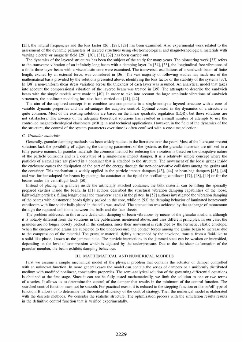
Fig. 1. The scheme of the test stand with three measured points.
A. Beam under a moving inertial load
Let us consider a simply supported Euler beam of the length L under a concentrated mass m, accompanied by a point
force P traveling at a variable velocity v(t). The moving load is accelerated to a fix velocity, than travels through a part of
the beam and then brakes before the end support. Examined problem was shown in Figure 1. Vertical displacement of the
beam is denoted by w. Coordinates x1 and x2 describe the positions of the viscous supports. At x = x3 we place the spring
that decrease the static displacement of the flexible beam. Differential equation of motion can be written in the following
form
EI∂4w(x, t)
∂ x4+ ρA
∂2w(x, t)
∂ t2+ δ(x − x3) kw(x, t) +
2∑i=1
δ(x− xi) ci(t)∂w(x, t)
∂ t=
= δ(x− f(t))P − δ(x− f(t))md2w(f(t), t)
dt2.
(1)
We assume zero displacements and velocities as the initial conditions. At both ends the displacements are equal to zero. In
the Eqn. (1) E, I , ρA, k, c(t) are the Young modulus, inertia moment of the cross section, linear mass density, stiffness
and damping coefficients of the supports, respectively. The viscous term enables the control in time. The acceleration of the
moving mass describes the Renaudot formula
d2w(f(t), t)
dt2=
[∂2w(x, t)
∂t2+ 2v
∂2w(x, t)
∂x∂t+ v
2 ∂2w(x, t)
∂x2+ v
∂w(x, t)
∂x
]
x=f(t)
, (2)
where
f(t) = x0 + vt+1
2vt2 , (3)
describes the position of the load. Due to the moving inertial term the analytical solution of Equation (1) is unknown.
The sine Fourier transform that naturally fulfills boundary conditions leads to the coupled system of ordinary differential
equations of the 2nd order with respect to time. The solution of this system requires numerical integration.
The equation (1) is discretized with the finite element method. Stationary terms can easily be written in a discrete matrix
form. According to the Renaudot formula (2), all three matrices of the motion equation, i.e. mass, damping and stiffness,
must be modified by contributing mass matrices to a single finite element in every time step:
(M +Mm)wi+1 + (C+Cm)wi+1 + (K+Km)wi+1 = Fi+1 + e
im . (4)
i and i + 1 denote two successive whiles. M, C, and K are the mass, damping, and stiffness matrix, respectively. F is
the external load vector and e is the vector of nodal forces contributed by a concentrated mass, while w is the vector of
displacements. In one node we have both the vertical displacements and rotations of nodes. Index m indicates matrices that
contribute the influence of the moving mass. The term contributing the moving mass requires more complex analysis. We
can address the reader to [54]. The discretization of the term contributing the influence of the moving mass in the case of a
variable velocity gives three matrices, which, after multiplication by accelerations, velocities and displacements contribute
inertia, Coriolis, and centrifugal forces, respectively.
The virtual energy of the moving mass placed on a finite element of the length b = ∆x is written by multiplying the
force by the virtual displacement w∗(x)
Πm =
∫ b
0
w∗(x)δ(x − f(t))md2w(f(t), t)
dt2dx . (5)
2230

E1
E3
z,w
x,u
d
b
h
h
h2
3
1G
Fig. 2. Three-layered sandwich beam.
The discrete model of vibrations of a beam subjected to moving force has a form of a sequence of static problems. Each one
is described by a system of algebraic equations. A moving point mass is contributed by adding the matrices Mm, Cm, and
Km, to respective degrees of freedom in the global matrix of coefficients, and the vector em, to the right hand side vector.
We notice that the influence of the moving mass is proportional to the velocity v. Moreover, the acceleration v influences
the matrix Km. All the above matrices have simple forms since they are based on linear shape functions. They are valid for
both the Bernoulli-Euler beam and the Timoshenko beam. In our analysis the thin beam will be modeled as the first one.
More detailed description of the moving mass problem is given in [55], [56].
B. Vibrating cantilever beam
Theoretical analysis can not be performed for arbitrary structures with equal simplicity. For an analytical solution we
choose the simply supported beam as one of the most representative structures. The governing set of differential equations
for the vibrating sandwich beam was derived in [36]. The necessary assumptions and simplifications of the analytical model
are briefly described below. Let us consider a three-layered sandwich beam. Its cross-sectional geometry has a characteristic
width b and the thicknesses of each layer is h1, h2, and h3 (Figure 2). Longitudinal displacements u in the x direction and
transverse displacements w in the z direction of the beam were taken into account. The face-plates are purely elastic, with
Young modulus E1 and E3, respectively. The core is linearly viscoelastic and defined by shear modulus G. The mathematical
model is obtained under some physically simplifying assumptions. The shear strains in the outer layers and the stresses in
the longitudinal direction in the core were neglected. Moreover, the transversal strains in each layer were neglected as well,
so the displacements w of the entire cross-section of the beam are constant.
In order to determine the relationship between the longitudinal displacements u1 and u3, and the relationship between
their derivatives with respect to x, the condition of zero resultant axial force in the whole section was used. Finally, we
obtain∂4w
∂x4− gY
∂2w
∂x2+ g
db
Dt
E3h3∂u3
∂x=
p
Dt
, (6)
∂2u3
∂x2− g
bu3 = −gY
Dt
E3h3b2d
∂w
∂x, (7)
where
g =G
h2
(1
E1h1+
1
E3h3
), (8)
Y =d2b
Dt
E1h1E3h3
E1h1 + E3h3. (9)
We assume initial deflection and zero initial velocity. The shear modulus G is controlled. A more detailed discussion of
the presented analytical model can be found in [36]. This mathematical formulation will be used for the simply supported
three-layered beam with a controllable core.
C. Rotating structures
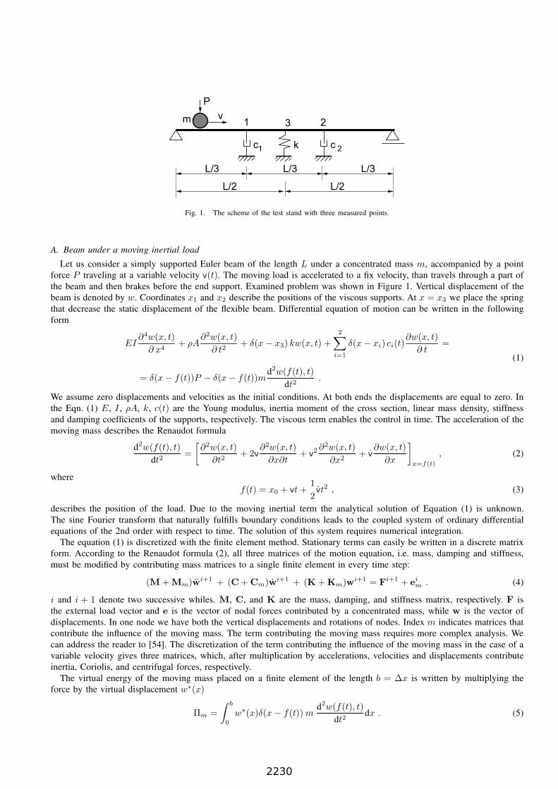
We consider the hyperbolic differential equation (10) which describes the motion of the rotating shaft (Figure 3). The
second equation (11) describes the motion of the damper. They are coupled at the point B:
−GI∂2ϕ
∂x2+ ρI
∂2ϕ
∂t2+ δ(x− xB)c
(∂ϕ
∂t− ∂ϑ
∂t
)= δ(x− xA) f(t) , (10)
Idd2ϑ
dt2+ c
(dϑ
dt− dϕ
dt
)= 0 . (11)
2231
c
L/4 L/2 L/4
A Bf(t)
Id
Fig. 3. Scheme of the problem for theoretical analysis.
We assume the following boundary conditions:
ϕ′(0, t) = 0, ϕ′(L, t) = 0 . (12)
Here, ϕ(x, t) is the angular displacement in time t of the point x of the shaft, ϑ is the angular displacement of the rotating
disk of the damper with inertia Id, and c is the damping coefficient. Two Dirac delta functions select arguments for the
point where the force is applied and the point for the damper. f(t) is an arbitrary external load function. Further we assume
it as a harmonic function F sin(ωt).The closed solution of the above equation is complicated. We take two ways to approximate the solution: an analytical
solution with a one term expansion of the Fourier series, and a semi-analytical solution with an n-term expansion. The first
solution allows us to examine features of the solution and test its sensitivity to the parameters. The second one allows of a
quantitative investigation.
Now we will solve the above system of differential equations with the angular displacements ϕ as the unknown functions.
We can apply the cosine Fourier transformation
Φj(t) =
∫ L
0
ϕ(x, t) cosjπx
Ldx , (13)
where
ϕ(x, t) =1
LΦ0(t) +
2
L
∞∑j=1
Φj(t) cosjπx
L, (14)
which fulfills the boundary conditions. For the reason of further analytical complexity we limit the solution to the first term
of the series (14). Finally, according to (14), the displacement including only the constant term can be written
ϕ(t) =1
LΦ0(t) . (15)
The solution is periodic.
IV. CONTROL STRATEGY
In this section we will focus our investigations on the control functions that minimize objective function J efficiently.
The control of the system can be performed in several ways to achieve prescribed goal. From the engineering point of view,
the following control functions can be essential:
• limited displacement of selected points of the structure,
• limited stress in chosen points of a structure,
• low accelerations in selected points or under the load.
The basic parameters of the system, i.e. the bending stiffness of the beam and the damping coefficient range, can be chosen
during the design stage as constant values. They are usually chosen at the design and optimization stage. They allow us to
provide the required load carrying capacity under the dynamic load. However, the damping coefficients that can vary, allows
to increase the performance of the system.
Let us first consider a vibrating beam in Ω = x : 0 ≤ x ≤ L, with boundary conditions in ∂Ω = 0, L, w(x) = 0,
w(x)′′ = 0, subjected to a gravity load P (x, t) = δ(x − vt)mg, with the concentrated inertia of the moving mass
δ(x− vt)mw(x, t)|x=vt. The beam is supported with the damping material c(x, t). The state of such a system is constituted
by vertical displacements w(x, u, t), and the control input u(x, t) as damping coefficients of dampers. The objective of the
control is to distribute the damping of each damper over time to achieve the desired vibrations, here denoted by wd(x, t).
2232
0 0.2
0.4 0.6
0.8 1
1
2 0
0.2 0.4 0.6 0.8 1
vt/L
No. of damper
0 0.2
0.4 0.6
0.8 1
1
2 0
0.2 0.4 0.6 0.8
1
vt/L
No. of damper
0 0.2
0.4 0.6
0.8 1
1
2 0
0.2 0.4 0.6 0.8 1
vt/L
No. of damper
a b c
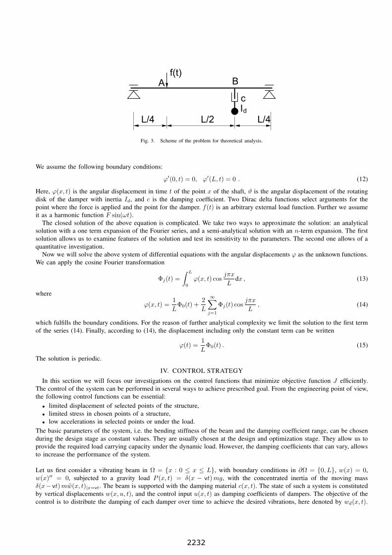
Fig. 4. Control functions in the case of partition into a) 10, b) 20, and c) 40 time intervals — minimizing displacements at the second measure point.
We assume a finite time horizon T . The optimization problem can be written in the following form.
Minimize J =1
2
∫ T
0
∫
Ω
[w(x, u, t)− wd(x, t)]2
dx dt+
+α
2
∫ T
0
∫
Ω
[u(x, t)]2
dx dt , (16)
subject to the constraints
Dw =d2w(ξ(t), t)
dt2+ P (x, t) , (17)
w(x, t)|t=0 = w0(x) on Ω , (18)
∂w(x, t)
∂t |t=0= w0(x) on Ω ,
w(k)(x, t) = wk(x), k = 1, 2, ...,
u ∈ U .
D is the spatial differential operator, (k), k=1,2,... are derivatives of the respective orders, ξ(t) is the position of the
load, and U is the control space. For (17) in the case of a beam subjected to a travelling inertial load we use (1). For
the layered cantilever beam we use (6–7) and for rotating shaft problem — (10–11). The solution of the above problem
minimizes displacements of a linear system of differential equations in a quadratic form. The problem is a linear quadratic
hyperbolic control problem with distributed control. However, we must emphasize the equation (1) has variable coefficients.
The treatment of these type of problems is difficult, due to the weak smoothing property of the associated solutions.
The numerical algorithms developed for optimization problems with partial differential equations are designed for convex
problems where the objective function is for example quadratic. In such cases problems have unique solutions. Moreover,
quadratic functions enable us to derive simple formulas for gradients by introducing the adjoint state. In our case the objective
function has local minima and the global search is required. Since gradient tools are ineffective and the number of design
variables is low, we can successfully use random methods. We will intentionally apply low number of of time intervals n,
since the controlled damping devices in real applications can not be switched instantaneously and certain delay in action is
typical. We will also consider higher n and compare time trajectories of considered design variables, i.e. damping.
The minimization process gives us the pair of control functions as depicted in Figure 4. The comparison of the displace-
ments of the 2nd measured point (Figure 1) in terms of the damping coefficients is presented in Figure 5. We notice that
higher damping enables more efficient reduction of amplitudes. Unfortunately, MR fluid disables high jump of dissipative
properties. We must assume the range of damping 100–500 Ns/m. We can state here that the higher number of the dampers
improves the efficiency of the damping strategy more than in the case of two dampers.
The same strategy of the control of the displacements in time was considered for the cantilever beam connected at its
tip with the magnetorheological elastomer. Only the 1st mode of vibration was excited. The rectangular on/off control was
performed, switching the magnetic flux density between 0 and 700 mT in the moments as presented in Figure 6. Small
number of decision variables results in sufficiently accurate normalized control function (Figure 6a). Increasing precision
improves shapes of slopes in the diagram. All the values practically vary between extreme values, i.e. zero and one. Our
2233

-0.050
-0.040
-0.030
-0.020
-0.010
0.000
0.010
0 0.5 1 1.5 2 2.5
disp
lace
men
t [m
]
time [s]
constant dampingcontrolled damping
-0.025
-0.020
-0.015
-0.010
-0.005
0.000
0.005
0 0.5 1 1.5 2 2.5
disp
lace
men
t [m
]
time [s]
constant dampingcontrolled damping
-0.020
-0.015
-0.010
-0.005
0.000
0.005
0 0.5 1 1.5 2 2.5
disp
lace
men
t [m
]
time [s]
constant dampingcontrolled damping
a
b c
Fig. 5. Displacements in time of the point 2 for different damping coefficients: a) c=500 Ns/m, b) c=2000 Ns/m, c) c=5000 Ns/m.
-8
-6
-4
-2
0
2
4
6
8
0 0.5 1 1.5 2 2.5 3 3.5 4
0.0
1.0
disp
lace
men
t [cm
]
c
ontro
l
time [s]
no controlconstant controlselective controlcontrol function
-8
-6
-4
-2
0
2
4
6
8
0 0.5 1 1.5 2 2.5 3 3.5 4
0.0
1.0
disp
lace
men
t [cm
]
c
ontro
l
time [s]
no controlconstant controlselective controlcontrol function
-8
-6
-4
-2
0
2
4
6
8
0 0.5 1 1.5 2 2.5 3 3.5 4
0.0
1.0
disp
lace
men
t [cm
]
c
ontro
l
time [s]
no controlconstant controlselective controlcontrol function
a b c
Fig. 6. The control function in the cantilever beam damped with MR elastomer, computed with partition of the time horizon into a) 40, b) 80, and c) 240time intervals.
control requires activation at the time of the extreme displacement and switching off in the static equilibrium state, i.e.
after 1/4 of the vibration period. The action of activating the magnetorheological elastomer is carried on during half of the
total time. For comparison, diagrams in Figure 6 depict vibrations without the control and with the permanent control. It is
obvious that the response of the structure vibrating with constant-in-time low or high shear stiffness of the inner layer and
excited with the same initial deflection differs only in period of vibrations.
Let us consider a rotating shaft. Successive time refinements into 10, 20, and 40 subdomains reduces the objective function
to 439, 401, and 377, respectively (Figure 7). The damping function takes on an almost harmonic shape with double the
frequency of the displacement solution.
The preliminary analytical results were compared with the numerical analysis. The finite element model was used. The
shaft was divided into 60 segments. The external load was applied to the node along 1/4 of its length and the damper
was fixed at 3/4 of the length. Furthermore, the right-hand end was elastically supported with a relatively small spring
kϕ=20 Nm. We use the bang-bang control of the damping. The action of the damper is demonstrated in Figure 8. The
significantly high amplitude of the shear strain for the undamped case decreases when the damper is activated constantly.
The controlled switching of the damping in time reduces the deformations significantly from 20% up to 50%. The applied
control coincides with that obtained with the analytical model (Figure 7).
0 0.1 0.2 0.3 0.4 0.5 0.6 0.7 0.8 0.9 1
0 1 2 3 4 5 6
c
t
step controlsmooth control
0 0.1 0.2 0.3 0.4 0.5 0.6 0.7 0.8 0.9
1
0 1 2 3 4 5 6
c
t
step controlsmooth control
0 0.1 0.2 0.3 0.4 0.5 0.6 0.7 0.8 0.9
1
0 1 2 3 4 5 6
c
t
step controlsmooth control
Fig. 7. The control of the damper in refined subdivisions of the period of vibrations.
2234

-6
-4
-2
0
2
4
6
0.2 0.3 0.4 0.5-0.4
0.0
0.4
Gϕ’
[Nm
]
c [N
s/m
]
t [s]
εϕc
-2
-1.5
-1
-0.5
0
0.5
1
1.5
2
0.25 0.26 0.27 0.28 0.29 0.3-0.4
-0.2
0.0
0.2
0.4
Gϕ’
[Nm
]
c [N
s/m
]
t [s]
εϕc
a b
-2
-1.5
-1
-0.5
0
0.5
1
1.5
2
0.25 0.26 0.27 0.28 0.29 0.3-0.4
-0.2
0.0
0.2
0.4
Gϕ’
[Nm
]
c [N
s/m
]
t [s]
εϕc
-2
-1.5
-1
-0.5
0
0.5
1
1.5
2
0.25 0.26 0.27 0.28 0.29 0.3-0.4
-0.2
0.0
0.2
0.4
Gϕ’
[Nm
]
c [N
s/m
]
t [s]
εϕc
c d
Fig. 8. Torque in the case of: a – no damping, b – continual damping, c, d – selective damping.
-0.060
-0.050
-0.040
-0.030
-0.020
-0.010
0.000
0.010
0 0.5 1 1.5 2 2.5 3 3.5 4 4.5
disp
lace
men
t [m
]
time [s]
const. damp.controlled
-0.060
-0.050
-0.040
-0.030
-0.020
-0.010
0.000
0.010
0 0.5 1 1.5 2 2.5
disp
lace
men
t [m
]
time [s]
const. damp.controlled
-0.050
-0.040
-0.030
-0.020
-0.010
0.000
0.010
0 0.5 1 1.5 2 2.5
disp
lace
men
t [m
]
time [s]
const. damp.controlled
Fig. 9. Comparison of displacements of point 2 in time, for velocity v=1, 2, and 3 m/s.
V. RESULTS
The unwanted vibrations of structures can be efficiently reduced with the controlled damping devices. The controlled
action significantly attenuates vibrations when compared to the constant activation of the damping. The mathematical analysis
performed with the simplified models proved that the optimum effect is ensured if the damping function has a special form,
different for each problem. The simply supported beam supplied with dampers, carrying the moving inertial load requires
special control, with null intervals at the beginning and in the final period of the process (Figure 4). The cantilever sandwich
beam treated with damper placed at a tip requires double frequency rectangular control function (Figure 6). In the case of
the rotating shaft it is a double frequency harmonic function (Figure 7). Numerical simulations proved that such a stepped
control function shape results in a reduction by about 20%-40% of the displacements over those with a constant control
with maximum power, depending on the type of the defined mechanical problem.
A. Vibrations of a beam under a moving load
Let us compare the efficiency of the simulated controlled damping in the case of various velocities v. Figure 9 depicts
displacements of the point No. 2 under the load moving at the velocity v=1 m/s, acceleration a=7 m/s2 and v=3 m/s,
a=4 m/s2. We notice that at the lower velocity the efficiency of displacement reduction is of the same range as in the case
of higher speed. The optimization procedure locates our solutions in local minima that have almost the same value of the
objective function.
2235
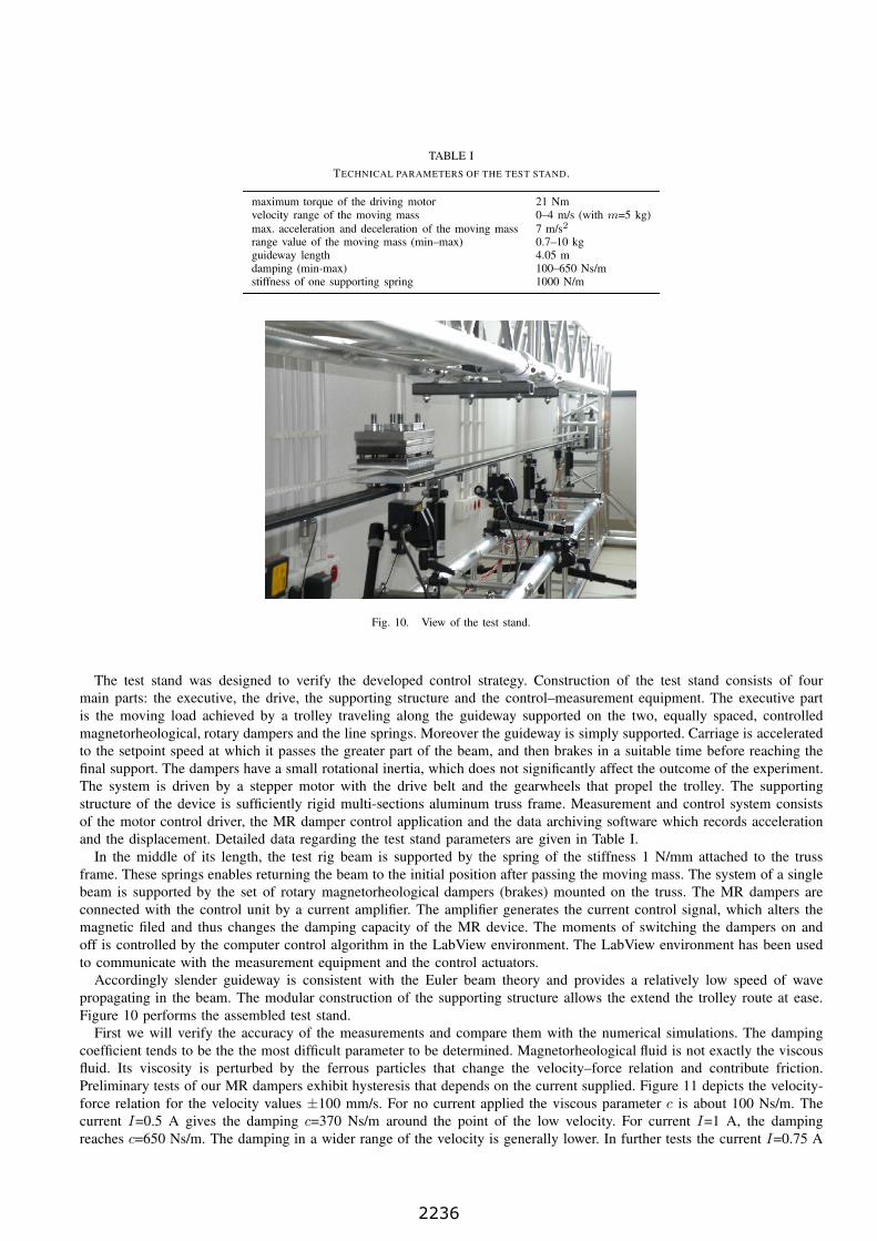
TABLE I
TECHNICAL PARAMETERS OF THE TEST STAND.
maximum torque of the driving motor 21 Nmvelocity range of the moving mass 0–4 m/s (with m=5 kg)
max. acceleration and deceleration of the moving mass 7 m/s2
range value of the moving mass (min–max) 0.7–10 kgguideway length 4.05 mdamping (min-max) 100–650 Ns/mstiffness of one supporting spring 1000 N/m
Fig. 10. View of the test stand.
The test stand was designed to verify the developed control strategy. Construction of the test stand consists of four
main parts: the executive, the drive, the supporting structure and the control–measurement equipment. The executive part
is the moving load achieved by a trolley traveling along the guideway supported on the two, equally spaced, controlled
magnetorheological, rotary dampers and the line springs. Moreover the guideway is simply supported. Carriage is accelerated
to the setpoint speed at which it passes the greater part of the beam, and then brakes in a suitable time before reaching the
final support. The dampers have a small rotational inertia, which does not significantly affect the outcome of the experiment.
The system is driven by a stepper motor with the drive belt and the gearwheels that propel the trolley. The supporting
structure of the device is sufficiently rigid multi-sections aluminum truss frame. Measurement and control system consists
of the motor control driver, the MR damper control application and the data archiving software which records acceleration
and the displacement. Detailed data regarding the test stand parameters are given in Table I.
In the middle of its length, the test rig beam is supported by the spring of the stiffness 1 N/mm attached to the truss
frame. These springs enables returning the beam to the initial position after passing the moving mass. The system of a single
beam is supported by the set of rotary magnetorheological dampers (brakes) mounted on the truss. The MR dampers are
connected with the control unit by a current amplifier. The amplifier generates the current control signal, which alters the
magnetic filed and thus changes the damping capacity of the MR device. The moments of switching the dampers on and
off is controlled by the computer control algorithm in the LabView environment. The LabView environment has been used
to communicate with the measurement equipment and the control actuators.
Accordingly slender guideway is consistent with the Euler beam theory and provides a relatively low speed of wave
propagating in the beam. The modular construction of the supporting structure allows the extend the trolley route at ease.
Figure 10 performs the assembled test stand.
First we will verify the accuracy of the measurements and compare them with the numerical simulations. The damping
coefficient tends to be the the most difficult parameter to be determined. Magnetorheological fluid is not exactly the viscous
fluid. Its viscosity is perturbed by the ferrous particles that change the velocity–force relation and contribute friction.
Preliminary tests of our MR dampers exhibit hysteresis that depends on the current supplied. Figure 11 depicts the velocity-
force relation for the velocity values ±100 mm/s. For no current applied the viscous parameter c is about 100 Ns/m. The
current I=0.5 A gives the damping c=370 Ns/m around the point of the low velocity. For current I=1 A, the damping
reaches c=650 Ns/m. The damping in a wider range of the velocity is generally lower. In further tests the current I=0.75 A
2236

c=500 Ns/m
c=650 Ns/m c=370 Ns/N
c=100 Ns/m
Fig. 11. The velocity-force relation in the MR damper.
was applied and the average damping reached 500 Ns/m.
The comparison between the simulated efficiency of the control and experimental data was made. Figure 12 depicts the
displacements in time at three points for the case of mass traveling at the velocity v=3 m/s. The pair of control functions is
depicted in Figure 12d. The 10% improvement of the results was noticed. The control functions have short breaks, sufficient
for easy rearrangement of the beam near the dampers. The velocity of v=2 m/s results in decreased efficiency of the control.
B. Vibrating cantilever sandwich beam
The experiments were carried out in order to find out whether the overall damping ratio of the structure could be increased.
by placing the magnetorheological elastomer at the tip of the beam. The theoretically obtained control strategy for the smart
core was verified and evaluated on the fabricated beam. The laboratory stand intended for the research of free vibrations
of beams consists of a fixture frame, supported firmly by a steady base plate. A massive mount, acting as a mechanical
vice attached to the frame, allows suspending the tested beam vertically in a clamped-free configuration. In order to set
the initial displacement of the beam, a holding band was connected to the free tip of the beam. The band was strained to
give an initial transverse displacement of 0.06 m. The data acquisition starts when the holding band is released and the
beam starts to oscillate around the equilibrium point. The component of the displacement of the amplitude was the basic,
directly measured variable. The displacement was measured at three points with dedicated laser sensors, with resolution up
to 8 µm and 10 kHz sampling frequency. The measurement system featured functions for compensating the inaccuracy of
measurements up to 15 of inclination angle. A 16-bit data acquisition card connected to a computer was used to record the
measurement results. The Programmable Logic Controller (PLC) with relay outputs allows to directly program the cycles of
turning the actuators on and off, depending on the control strategy. A photo of the real, deflected specimen and measurement
system is presented in Figure 13.
The first 60 seconds of vibrations were acquired. This gave us enough information about the process. These results
showed that if the smart material is embedded between the face layers, the overall damping of the beam increases. Figure 14
illustrates the first segment of 30 seconds of vibration. The presented plots show how the magnetic field affects the amplitude
of the displacement of the beam’s tip for an initial deflection of 0.06 m, in three different cases: MRE not activated, MRE
turned on constantly, and MRE activated for selected moments. The case of free vibrations of a beam with the non-activated
smart core is treated as the reference measurement. In this case, the only damping mechanisms were related to the shear
deformation of the non-activated MRE.
All three curves in Figure 14 exhibit damping. The elastomer, although merged locally in the sandwich beam, causes a
significant decrease of amplitudes both in constant and periodic magnetic action. The experiment differs in this case from
our theoretical analysis. However, the efficiency of the control with a small elastic inclusion, related to the entire length
of the beam is effective. Longer observations allowed us to estimate the rate of damping. After 60 s, the amplitude of
displacement for 0 mT is 12 mm, which is 20% of the initial deflection. If MRE was activated constantly, the amplitude
after 60 s of vibrations decreased to 4.2 mm, which is 7% of the initial value. In the controlled case the amplitude dropped
to 2.6 mm, i.e. to 4% of the initial value.
2237

-0.03
-0.025
-0.02
-0.015
-0.01
-0.005
0
0.005
0 0.5 1 1.5 2
disp
lace
men
t [m
]
time [s]
permanent dampingcontrolled damping
-0.05-0.045-0.04-0.035-0.03-0.025-0.02-0.015-0.01-0.005
0 0.005
0 0.5 1 1.5 2
disp
lace
men
t [m
]
time [s]
permanent dampingcontrolled damping
a b
-0.045-0.04-0.035-0.03-0.025-0.02-0.015-0.01-0.005
0 0.005
0 0.5 1 1.5 2
disp
lace
men
t [m
]
time [s]
permanent dampingcontrolled damping
0 0.1 0.2 0.3 0.4 0.5 0.6 0.7 0.8
0 0.5 1 1.5 2
cont
rol u 1[A
]
time [s]
0 0.1 0.2 0.3 0.4 0.5 0.6 0.7 0.8
0 0.5 1 1.5 2
cont
rol u 2[A
]
time [s]
c d
Fig. 12. Displacements in time in the 1st (a), 2nd (b), 3rd (c) point, and the control functions (d), in the case of controlled damping and permanentdamping at v=3 m/s, a=4 m/s2.
Fig. 13. Photography of the deflected sandwich beam with embedded magnetorheological elastomer.
2238

Fig. 14. Displacement in time for different states of MRE damping element caused by the magnetic field.
driving motorinertial disks MR damperselectric brake torque meter
Fig. 15. The scheme of the test stand.
C. Rotating shaft
Further experimental verification of the theory was performed on the test stand. It differs from our previous model, since it
has not a uniform cross section area and has a point masses. We will try to apply our control technique to this real structure.
In the laboratory drive system presented in Figure 15 the power is transmitted from the servo-asynchronous motor to the
driven machine tool in the form of an electric brake. The drive system, which is made up of a multi-segmented shaft, is
supported by bearings. It contains an electromagnetic overload coupling, two multi-disk elastic couplings with built in torque
meters, two rotary dampers with magneto-rheological fluid, and a measurement control system. Moreover, this drive system
is equipped with two inertial disks with adjustable mass moments of inertia and the possibility of axial positioning. This
enables us to tune the drive train to the proper natural frequencies. The control voltage is applied to the magneto-rheological
damper with sliders. The external magnetic field acts on the fluid inside the damper. Consequently, the characteristics of the
magneto-rheological fluid are changed, in a way that controls the torsional vibrations. Since the average rotational speeds of
the ring and of the shaft are similar, only small wearing effects can be expected and vibrations can be suppressed without
significantly influencing the rigid body motion of the drive system.
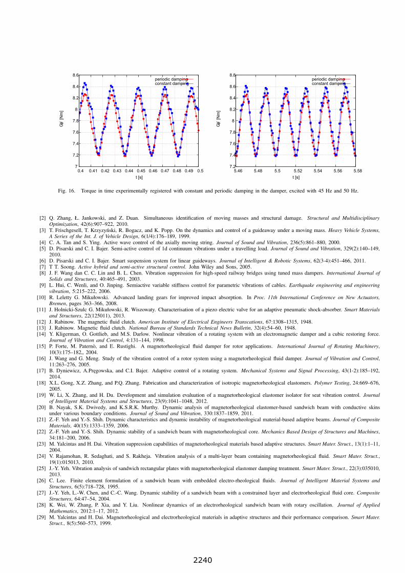
The left hand end of the shaft was excited by a driving motor with a sine torque. Its amplitude was set to 1 Nm. The
frequency as set within the range 30–60 Hz. The right hand end was terminated with an electric brake. At this point, the
boundary condition ϕ(l, t) = 0 was used. This condition can be changed in other tests and, for example, a constant rotational
velocity can be imposed. However, we can always shift our results as a rigid body motion. Figure 16 depicts torque in time
experimentally registered with the constant and periodic damping action of the device, excited with 45 Hz and 50 Hz. The
advantages of the proposed controlled system are clearly depicted.
REFERENCES
[1] Ł. Jankowski. Off-line identification of dynamic loads. Structural and Multidisciplinary Optimization, 37(6):609–623, 2009.
2239
7
7.2
7.4
7.6
7.8
8
8.2
8.4
8.6
0.4 0.41 0.42 0.43 0.44 0.45 0.46 0.47 0.48 0.49 0.5
GIϕ’
[Nm
]
t [s]
periodic dampingconstant damping
7.2
7.4
7.6
7.8
8
8.2
8.4
8.6
8.8
5.46 5.48 5.5 5.52 5.54 5.56 5.58
GIϕ’
[Nm
]
t [s]
periodic dampingconstant damping
Fig. 16. Torque in time experimentally registered with constant and periodic damping in the damper, excited with 45 Hz and 50 Hz.
[2] Q. Zhang, Ł. Jankowski, and Z. Duan. Simultaneous identification of moving masses and structural damage. Structural and Multidisciplinary
Optimization, 42(6):907–922, 2010.[3] T. Frischgesell, T. Krzyzynski, R. Bogacz, and K. Popp. On the dynamics and control of a guideaway under a moving mass. Heavy Vehicle Systems,
A Series of the Int. J. of Vehicle Design, 6(1/4):176–189, 1999.[4] C. A. Tan and S. Ying. Active wave control of the axially moving string. Journal of Sound and Vibration, 236(5):861–880, 2000.[5] D. Pisarski and C. I. Bajer. Semi-active control of 1d continuum vibrations under a travelling load. Journal of Sound and Vibration, 329(2):140–149,
2010.[6] D. Pisarski and C. I. Bajer. Smart suspension system for linear guideways. Journal of Intelligent & Robotic Systems, 62(3-4):451–466, 2011.[7] T T. Soong. Active hybrid and semi-active structural control. John Wiley and Sons, 2005.[8] J. F. Wang dan C. C. Lin and B. L. Chen. Vibration suppression for high-speed railway bridges using tuned mass dampers. International Journal of
Solids and Structures, 40:465–491, 2003.[9] L. Hui, C. Wenli, and O. Jinping. Semiactive variable stiffness control for parametric vibrations of cables. Earthquake engineering and engineering
vibration, 5:215–222, 2006.[10] R. Leletty G. Mikułowski. Advanced landing gears for improved impact absorption. In Proc. 11th International Conference on New Actuators,
Bremen, pages 363–366, 2008.[11] J. Holnicki-Szulc G. Mikułowski, R. Wiszowaty. Characterisation of a piezo electric valve for an adaptive pneumatic shock-absorber. Smart Materials
and Structures, 22(125011), 2013.[12] J. Rabinow. The magnetic fluid clutch. American Institute of Electrical Engineers Transcations, 67:1308–1315, 1948.[13] J. Rabinow. Magnetic fluid clutch. National Bureau of Standards Technical News Bulletin, 32(4):54–60, 1948.[14] Y. Kligerman, O. Gottlieb, and M.S. Darlow. Nonlinear vibration of a rotating system with an electromagnetic damper and a cubic restoring force.
Journal of Vibration and Control, 4:131–144, 1998.[15] P. Forte, M. Paternò, and E. Rustighi. A magnetorheological fluid damper for rotor applications. International Journal of Rotating Machinery,
10(3):175–182„ 2004.[16] J. Wang and G. Meng. Study of the vibration control of a rotor system using a magnetorheological fluid damper. Journal of Vibration and Control,
11:263–276, 2005.[17] B. Dyniewicz, A.Pregowska, and C.I. Bajer. Adaptive control of a rotating system. Mechanical Systems and Signal Processing, 43(1-2):185–192,
2014.[18] X.L. Gong, X.Z. Zhang, and P.Q. Zhang. Fabrication and characterization of isotropic magnetorheological elastomers. Polymer Testing, 24:669–676,
2005.[19] W. Li, X. Zhang, and H. Du. Development and simulation evaluation of a magnetorheological elastomer isolator for seat vibration control. Journal
of Intelligent Material Systems and Structures, 23(9):1041–1048, 2012.[20] B. Nayak, S.K. Dwivedy, and K.S.R.K. Murthy. Dynamic analysis of magnetorheological elastomer-based sandwich beam with conductive skins
under various boundary conditions. Journal of Sound and Vibration, 330:1837–1859, 2011.[21] Z.-F. Yeh and Y.-S. Shih. Dynamic characteristics and dynamic instability of magnetorheological material-based adaptive beams. Journal of Composite
Materials, 40(15):1333–1359, 2006.[22] Z.-F. Yeh and Y.-S. Shih. Dynamic stability of a sandwich beam with magnetorheological core. Mechanics Based Design of Structures and Machines,
34:181–200, 2006.[23] M. Yalcintas and H. Dai. Vibration suppression capabilities of magnetorheological materials based adaptive structures. Smart Mater. Struct., 13(1):1–11,
2004.[24] V. Rajamohan, R. Sedaghati, and S. Rakheja. Vibration analysis of a multi-layer beam containing magnetorheological fluid. Smart Mater. Struct.,
19(1):015013, 2010.[25] J.-Y. Yeh. Vibration analysis of sandwich rectangular plates with magnetorheological elastomer damping treatment. Smart Mater. Struct., 22(3):035010,
2013.[26] C. Lee. Finite element formulation of a sandwich beam with embedded electro-rheological fluids. Journal of Intelligent Material Systems and
Structures, 6(5):718–728, 1995.[27] J.-Y. Yeh, L.-W. Chen, and C.-C. Wang. Dynamic stability of a sandwich beam with a constrained layer and electrorheological fluid core. Composite
Structures, 64:47–54, 2004.[28] K. Wei, W. Zhang, P. Xia, and Y. Liu. Nonlinear dynamics of an electrorheological sandwich beam with rotary oscillation. Journal of Applied
Mathematics, 2012:1–17, 2012.[29] M. Yalcintas and H. Dai. Magnetorheological and electrorheological materials in adaptive structures and their performance comparison. Smart Mater.
Struct., 8(5):560–573, 1999.
2240

[30] Q. Sun, J.-X. Zhou, and L. Zhang. An adaptive beam model and dynamic characteristics of magnetorheological materials. Journal of Sound and
Vibration, 261:465–481, 2003.[31] K. Wei, G. Meng, W. Zhang, and S. Zhu. Experimental investigation on vibration characteristics of sandwich beams with magnetorheological
elastomers cores. J. Cent. South Univ. Technol., 15:239–242, 2008.[32] G. Hu, M. Guo, W. Li, H. Du, and G. Alici. Experimental investigation of the vibration characteristics of a magnetorheological elastomer sandwich
beam under non-homogeneous small magnetic fields. Smart Mater. Struct., 20(12):127001, 2011.[33] E.M. Kerwin. Damping of flexural waves by a constrained viscoelastic layer. J. Acoust. Soc. Am., 31(7):952–962, 1959.[34] R.A. DiTaranto. Theory of vibratory bending for elastic and viscoelastic layered finite-length beams. Journal of Applied Mechanics, 32(4):881–886,
1965.[35] R.A. DiTaranto and W. Blasingame. Composite damping of vibrating sandwich beams. J. Eng. Ind., 89(4):633–638, 1967.[36] D.J. Mead and S. Markus. The forced vibration of a three-layer, damped sandwich beam with arbitrary boundary conditions. Journal of Sound and
Vibration, 10(2):163–175, 1969.[37] R.C. Kar and W. Hauger. Stability of a sandwich beam subjected to a non-conservative force. Comput. and Struct., 46(5):955–958, 1993.[38] A. Bhimaraddi. Sandwich beam theory and the analysis of constrained layer damping. Journal of Sound and Vibration, 179(4):591–602, 1995.[39] C.L. Sisemore and C.M. Darvennes. Transverse vibration of elastic-viscoelastic-elastic sandwich beams: compression-experimental and analytical
study. Journal of Sound and Vibration, 252(1):155–167, 2002.[40] D. Backstrom and A.C. Nilsson. Modelling the vibration of sandwich beams using frequency-dependent parameters. Journal of Sound and Vibration,
300:589–611, 2007.[41] M.W. Hyer, W.J. Anderson, and R.A. Scott. Non-linear vibrations of three-layer beams with viscoelastic cores I. Theory. Journal of Sound and
Vibration, 46(1):121–136, 1976.[42] A.V. Krys’ko, M.V. Zhigalov, and O.A. Saltykova. Control of complex nonlinear vibrations of sandwich beams. Russian Aeronautics (Iz.VUZ),
51(3):238–243, 2008.[43] M. Saeki. Impact damping with granular materials in a horizontally vibrating system. Journal of Sound and Vibration, 251(1):153–161, 2002.[44] M. Sanchez, G. Rosenthal, and L.A. Pugnaloni. Universal response of optimal granular damping devices. Journal of Sound and Vibration,
331:4389–4394, 2012.[45] A. Q. Liua, B. Wang, Y. S. Choo, and K. S. Ong. The effective design of bean bag as a vibroimpact damper. Shock and Vibration, 7:343–354, 2010.[46] A. Papalou and S. F. Masri. Response of impact dampers with granular materials under random excitation. Earthquake Engineering & Structural
Dynamics, 25:253–267, 1996.[47] I. Yokomichi, M. Aisaka, and Y. Araki. Impact damper for granular materials for multibody system. In Proceedings of the Fifth International
Congress on Sound and Vibration, pages 1117–1124, University of Adelaide, Adelaide, South Australia, 1997.[48] K. T. Andrews and M. Shillor. Vibrations of a beam with a damping tip body. Mathematical and Computer Modelling, 35:1033–1042, 2002.[49] K. M. Mao, M. Y. Wang, and Z. W. Xu ad T. N. Chen. Simulation and characterization of particle damping in transient vibrations. Journal of
Vibration and Acoustics, 126:202–211, 2004.[50] D. N. J. Els. Damping of rotating beams with particle dampers. In 50th Structures, Structural Dynamics, and Materials Conference, pages 2009–2688,
Palm Springs, California, 2009.[51] Z. Xu, M. Y. Wang, and T. Chen. Particle damping for passive vibration supression: Numerical modeling with experimental verification. In Proceedings
of DETC03, pages 1–9, Chicago, Illinois, USA, 2003.[52] J. G. McDaniel and P. Dupont. A wave approach to estimating frequency-dependent damping under transient loading. Journal of Sound and Vibration,
231(2):433–449, 2000.[53] B. Wang and M. Yang. Damping of honeycomb sandwich beams. Journal of Materials Processing Technology, 105:67–72, 2000.[54] B. Dyniewicz and C.I. Bajer. New consistent numerical modelling of a travelling accelerating concentrated mass. World Journal of Mechanics,
2(6):281–287, 2012.[55] B. Dyniewicz. Space-time finite element approach to general description of a moving inertial load. Finite Elem. Anal. and Des., 62:8–17, 2012.[56] C.I. Bajer and B. Dyniewicz. Numerical analysis of vibrations of structures under moving inertial load. Springer, 2012.
2241