smart contact lenses: the future is now - idaho...
TRANSCRIPT

9/11/2013
1
Smart Contact Lenses: The Future is Now
Jerome A. Legerton, OD, MS, MBA, FAAO
“Everyone who's ever taken a shower has an idea. It's the person who gets out of the shower, dries off and does something about it who makes a difference.“ --Nolan Bushnell, American engineer and entrepreneur
Jerome A. Legerton
OD Los Angeles College of Optometry 1968
MS Trinity School of Graduate Studies 1983
MBA Pepperdine University 1991
FAAO 1973
My Journey
• 26 years in Private Practice
• 19 years in product development
• 38 Issued US Patents; 53 pending applications • 3 Alcon (PBH< WJ< Ciba); Multifocal contact lenses • 2 AMO (VISX); Presbyopia laser surgery • 13 Paragon Vision Sciences; Paragon CRT® , Refractive Error
Regulation, NormalEyes® 15.5 mini-scleral lenses
• 11 Synergeyes® ; Family of lenses and processes • 2 Preventive Ophthalmics, Inc; DxAMD™ Early detection AMD • 1 Innovega, Inc; iOptik™ wearable computer • 5 VICOH, LLC; Family of contact lens designs • 1 Eye Care for Humanity; low cost spectacle eyewear
“It's not that I'm so smart, it's just that I stay with problems longer.” --Albert Einstein
Interests in products mentioned in this presentation:
Innovega Inc.
Paragon Vision Sciences, Inc.
Carl Zeiss Vision , Inc.
VICOH, LLC
Disclosures:
What will photonics, electronics and information technology bring to the field of contact lenses and ophthalmic optics?
Let’s look into the future
“Only those who will risk going too far can possibly find out how far one can go.“
--T.S. Eliot, American-British writer
What trends will impact the contact lens and ophthalmic lens industry?
• Increase in incidence and prevalence of myopia
• Increased urbanization along with indoor life style
• Graying demographics of developed nations
• Miniaturization allowing for electronic components in lenses
• Precision metrology and manufacturing allowing for enhanced control of optical path
• Consumer appetite for mobile information and entertainment
• Peripheral or implanted sensors
and sending units to monitor
human anatomy and physiology
A Study of Trends Will Make You a Futurist

9/11/2013
2
• Vernor Vinge, PhD: Rainbow’s End
• The Terminator
• Mission Impossible
The Futurists
• Micro-Electro Mechanical Systems
• Every year components get smaller [Bell’s Law] • Now have batteries, antenna, LEDs, mechanical and electronic
sensors
• Small enough and low cost enough to be put in a contact lens
• Nano-technology
• Components for modulated drug delivery
• Light filtering • Spectral and polarizing
• Micro-optical elements
• Diamond turning and molding to sub-micron accuracy
MEMS and Nanotechnology
Bell’s Law
• “The eye is the light of the body” • Close to the central nervous system
• Transparent
• Tear film communicates body chemistry
• Aqueous communicates
• Crystalline lens communicates
• IOP changes corneal geometry
• Drug delivery enigma – need for slow delivery over time
• Control of optical path – central and off axis focus
• Control of illumination – role of central and off axis light
• Advantages of eye-borne optics – field of view and low bulk
Why Contact Lenses?
IOP Sensing – “TriggerFish”
STMicroelectronics and Sensimed • Nano-sensors fabricated in silicon-based MEMS
technology • Measure the shape change of eye with pressure • Couple with drug delivery (future)
Intraocular 1.5 mm3 IOP Monitor

9/11/2013
3
Power Sources
University of California Davis • Conductive silver wires used to measure
pressure changes
Another IOP Sensing Contact Lens
Contact lenses detect blood sugar changes
University of Western Ontario in Hamilton (Jin Zhang ) • Hydrogel contact lenses with nano-particles • React with glucose molecules found in tears • Chemical reaction changes color
Microsoft and University of Washington
Microsoft and the University of Washington • Electronic contact lens that can non-invasively monitor
and wirelessly report blood sugar levels; • Employs a single LED
First Phase Animal Testing Auburn University
• Imprinted contact lens
• Successful in sustained drug delivery
Smart Drug Delivery Contact Lenses
A. Tieppo, C.J. White, A.C. Paine, M.L. Voyles, M.K. McBride, M.E. Byrne Sustained in vivo release from imprinted therapeutic contact lenses; Journal of Controlled Release, October 2011
9/11/2013
4
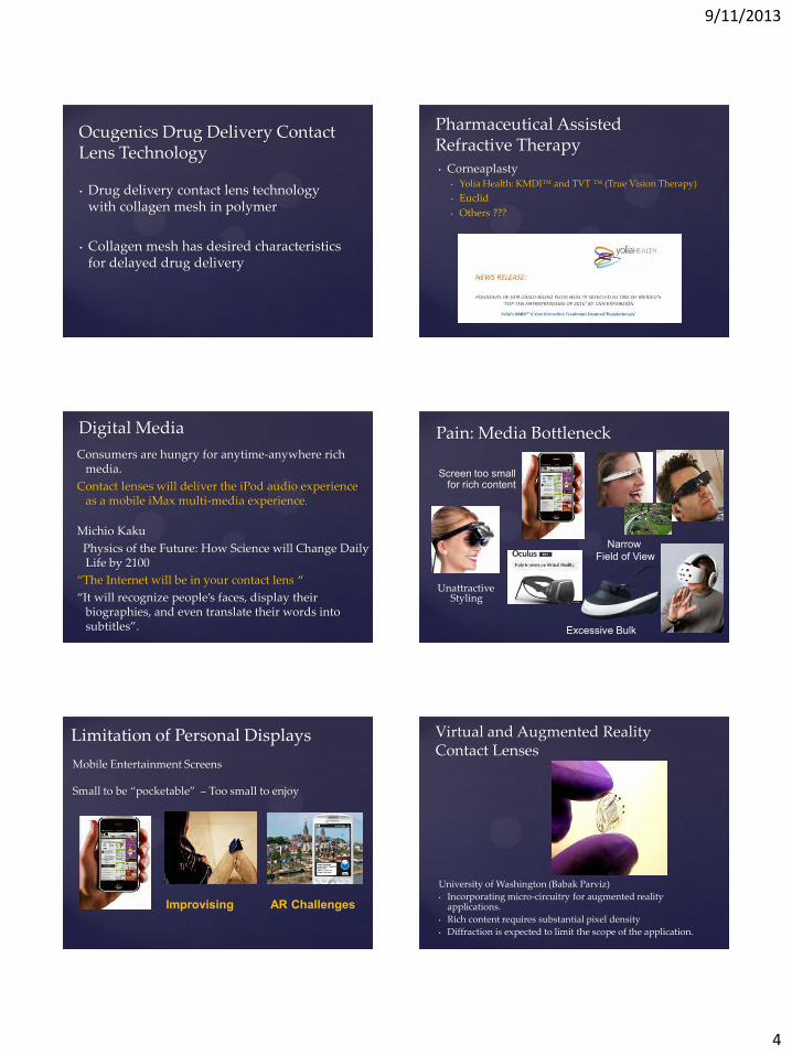
• Drug delivery contact lens technology with collagen mesh in polymer
• Collagen mesh has desired characteristics for delayed drug delivery
Ocugenics Drug Delivery Contact Lens Technology
• Corneaplasty • Yolia Health: KMDI™ and TVT ™ (True Vision Therapy)
• Euclid
• Others ???
Pharmaceutical Assisted Refractive Therapy
Consumers are hungry for anytime-anywhere rich media.
Contact lenses will deliver the iPod audio experience as a mobile iMax multi-media experience.
Michio Kaku
Physics of the Future: How Science will Change Daily Life by 2100
“The Internet will be in your contact lens “
“It will recognize people’s faces, display their biographies, and even translate their words into subtitles”.
Digital Media
Screen too small for rich content
Pain: Media Bottleneck
Unattractive Styling
Narrow Field of View
Excessive Bulk
Limitation of Personal Displays
Mobile Entertainment Screens Small to be “pocketable” – Too small to enjoy
Improvising AR Challenges
University of Washington (Babak Parviz)
• Incorporating micro-circuitry for augmented reality applications.
• Rich content requires substantial pixel density
• Diffraction is expected to limit the scope of the application.
Virtual and Augmented Reality Contact Lenses

9/11/2013
5
• Insert picture
Semprius Micro-display Lens
• 32x32 display using OLED pixels • Solution to the power issue - thin film micro-solar cells
• Micro-Electro-Mechanical Systems • Light emitting • Power sources • Sensors • Processors • Antenna • Oxygen generators
• Micro-optical components • Lenslets • Filters • Reflectors/ deflectors • Diffusers
• Nano-structures • Drug delivery • Anti-microbial products and systems
The Era of Intra-lens Components
The Problem: • Eyewear Digital Systems Today
• High bulk • Not stylish • Small field of view
• Rich Media will require • Further miniaturization • Optics that enable greater than 60° FOV • Performance in bright ambient lighting
Delivering Wearable Digital Media
Copyright 2011
0 20 40 60 80 100 120Field Of View (Degrees)
BU
LK
Eliminating Optics in Eyewear Breaks the FOV/Bulk Trade-off
yVu Vuzix TDVisor eMagin NVIS RockwellCollins
NVIS
iOptik
Passive Optics: Innovega Inc. iOptik Contact lens
Solution: Contact Lens Enabled Wearable Displays
Inc. Magazine April, 2012 Centerfold
iOptik™ Contact Lens Built on the Paragon NormalEyes 15.5 mini-scleral Platform Outer lens provides normal vision for real world Center lens streams HD/3D Digital Media from eyewear
Paragon Vision Sciences is the development partner

9/11/2013
6
• Passes real world and rejects display light
• Passes display light and rejects real-world
• Enables wearer to view near-eye media without altering normal vision
How iOptik Display Works
Contact Lens
Small focusing Lens
Center RGB Band-Pass Filter
Polarizer filterin outer portion
Contact Lens
Small focusing Lens
Center RGB Band-Pass Filter
Polarizer filterin outer portion
Off-axis projection to transparent holographic film on spectacle lens
Gas Permeable Nano-polarizer Contact Lens
• Off axis projection
• LCOS
• Laser Pico-projector (Microvision)
• Film in spectacle lens
• Holographic volumetric film
• Transflective film (Microvision)
• Speckle free
• Eye trackers
Technology in Development iOptik HMD System
• Optics embedded in contact lens enable focus of imagery on spectacle lens
• LCOS module projects image onto holographic reflector spectacle lens
• Wearer can see unobstructed surrounding environment and projected image simultaneously
• Contact lens optics provide high spatial resolution in direction of gaze, lower resolution in peripheral vision
• Retro-reflector embedded in contact lens enables high-speed pupil tracking without imaging
Eye Tracking Sensor
LCOS Projector Module
Holographic Reflector Spectacle Lens
High Resolution Imager
Battery and Processor
Contact Lens Enabled AR Wearable Display Elements
Contact lens with display optics
LCOS Projector
120° FOV Imager
Pupil Tracking Sensors
Processor
Batteries
Frame
Holographic Transparent Reflector
Eyewear Configuration

9/11/2013
7
Initial Projector Optical Design
• Complex aspheric projection optics required to achieve off-axis, short working distance projection
• Latest design has reasonable size and weight, and image resolution at the pixel level over the foveal image region
Perspective Views of Spectacle Lenses and Projector
• Orientation between each spectacle lens and its corresponding projector module must remain constant
• Nose-piece will be adjustable z and y axis to center lenses to eyes
• PD adjustments in projector modules
• Different eyewear sizes required to support diversity of head width and PD
Eyewear Configuration
100% stereoscopic overlap
Anthropometric Model
Head Metrics Projector Placement Imposed

9/11/2013
8
February to June Spectacle Lens Reflector Function
• Passes surrounding environment light un-modified
• Reflects display light towards pupil
• Expands reflected beams at each pixel to fill the pupil at all gaze angles
Transflective Diffuser
• Micro lens array sandwiched between two transparent substrates
• MLA elements receive narrow band reflective coating
• Refractive index of optical adhesive laminating substrates together matches index of MLA
• Transmitted light passes through constant index of refraction without distortion
• Projected light is reflected with diverging angles due to curved nature of reflective coating
• Uses specular reflection resulting in no speckle
Transflective Diffuser Demonstration
• Sample MLA has poor surface quality
• 100 um pitch (desired pitch is 25 um) – Results in low resolution image “spots”
• Demonstrates clear transmission simultaneous with diffuse projected image reflection
Poor Surface Quality
25 Micron Transflective Reflector Configuration
Transflective Film Performance

9/11/2013
9
Copyright 2011
• Retro-reflector is embedded into each contact lens
• Scleral contact lenses are rotationally and laterally stable on eye
• IR LED illuminates eyes with low power IR
• Photo-sensor detects position of retro-reflector
• A calibration step is required to initially register the virtual image to the real world.
• Low latency tracking with no image processing required
Pupil Tracking
Retro-reflector in Contact Lens
Quad-photo-diode position detection
Pupil Tracking Geometry Unknowns (10 Total):
– 2 axis left eye rotation – 2 axis right eye rotation – 3 axis eyewear rotation – 3 axis eyewear translation
Knowns (6 Total): – Azimuth, elevation, and distance
to eye from left eye sensor pair – Azimuth, elevation, and distance
to eye from left eye sensor pair
Physical constraints – Eyes track together in vertical
direction (eliminates One unknown)
– Assume eyewear pitch rotation is centered at ears and is therefore largely a Y translation at eyes
– Assume tight eyewear fit does not allow yaw rotation or X translation.
One retro reflector and two sensors per eye offset vertically on outside corner of frames (only one sensor per eye shown in diagram for clarity)
Pupil Tracking
• Two retro-reflectors get imbedded into HMD contact lenses – One reflects 850 nm IR – Other reflects 950 nm IR
• Two emitter/detector sensors (per eye) mounted on spectacles • Each emitter/detector sensor has one 850 nm LED and one 950 nm LED.
– Illumination at alternating 50% duty cycles
• Achieves measurement of four angles per eye • Allows measurement of yaw rotation for each eye, combined eye pitch rotation,
and 5 axis of spectacle movement – Spectacle pitch and Y translation are combined
Warfighter Embodiment
• 720P
• 90° FOV
• Full Color
• 3-D stereoscopic
• Variable transparency (5% to 80%)
• HDMI tethered connection to smart phone or laptop
• Lithium ion battery mounted in head strap recharged via USB connection
Consumer Embodiment Mobile “Display Accessory”
Holographic Lens
LCOS Projector
Micro HDMI or USB/MHL Connector
Audio
Smart Phone
Micro HDMI Connector

9/11/2013
10
Transparent Optics
Media Interface blends Media with Surroundings
Copyright 2011
Emerging Application: Augmented Reality
Good AR requires transparency and
large fields of view
Copyright 2011
Bright Daylight Night
High Resolution and Contrast in All Lighting Conditions
Without Contact
Lens
With Contact
Lens
Copyright 2011
Naval Medical Center San Diego, July 2012
First iOptik Clinical Testing
Serious Gamers • First-person, photo-real immersive 3D gaming • More than 20% of 15-40 year old, “serious gamers”
already wear contact lenses Medical Applications
• Medical and Surgical Visualization and Training • Low Vision
Defense Training & Simulation • Presently a $1B per year business (US alone)
Defense and Intelligence Field Operations • Next Generation Night Vision • Situation awareness • Remote weapon sight
Ultimately most anyone who wants to wear their media and computers
Analog: How many of you are wearing a wristwatch?
Your Future Patients Mini-Scleral Platform (Paragon NormalEyes ™ 15.5)
• Filters easier to encapsulate in rigid substrate • Lens stability
• Rotationally • Translationally
• Eye protection factor • Foreign body migration • Water environment • Ballistic protection
Hybrid or Composite Platform • Same rigid substrate advantages • Easier to fit • Comfort and convenience
First Adopter Platforms

9/11/2013
11
The Un Met Medical Need Low VisionMarket “Pain”
Graying of Europe, Japan and the United States • Age-related Macular Degeneration (AMD)
• Greater span of impact on individuals who are otherwise active and healthy
• Prevalence of DIGITAL media and information
• Stimulates greater need for image augmentation for low-vision patients
Low Vision • Relative distance and angular magnification limited
• Field of view,
• Control of brightness, wavelength and contrast.
• No useful means of field expansion or night vision enhancement for patients with field losses and reduced low light acuity
• Need for useful augmented reality eyewear for the low partially sighted patients
Innovega Solution
• iOptik™ offers full field, high resolution, variable image amplification for all visual stimuli.
• Video and text and real time camera and sensor feed
• Field expansion through digital manipulation of camera captured data
• Night vision display to increase and equalize the brightness of displayed images
• Augmented reality to “bold border” objects to assist orientation and mobility of very low partial sighted patients
Improving Quality of Life for Low-Vision Patients • Electronic image amplification offers a higher contrast ratio in a full field of view without optical distortion and the need to control ambient illumination • Camera driven system provides real time “telescopic” image amplification in a full field of view • Camera driven or digital feed reading system provides real time “microscopic” image amplification at a normal working distance • Night vision sensor provides wide field amplification in scotopic or mesopic illumination for retinitis pigmentosa • Simultaneous display of off blind field for hemianopia • All digital data become available to the low vision patient as an alternative to current computer monitor and iPad systems.
Benefits of iOptik™ System for Low Vision
• Utilizes available high-definition digital processing and HD displays.
• Illumination, contrast, position and wavelength adjustment algorithm further enhance vision.
• 60 to 120 degree fields provide display of text and live or produced video feed in a magnified and augmented view which far surpasses optical magnification (more view or text presented in a line)
• Use of contact lens and light-weight eyewear provides comfort, mobility and freedom for all day vision enhancement.
• Live camera feed allows for normal distances for holding text and objects along with visual access to the distance world that is not possible with telescopic lenses
• Transparent displays provide the potential for augmented reality for low form vision patients
• Night vision infrared or temperature sensors can provide useful images for orientation and mobility
Advantage of Field of View
1X in31°
5X in 31°
5X in 93°
Competitive Head Mounted Displays • All require mounting optics in eyewear to focus
display directly or by total internal reflection optics • Resultant limited field of view (approximate maximum 40
degrees)
• Thickness of display and optical system plus vertex distance results in front surface minimum 25 mm from eye
• Pupillary distance sensitivity and SKU or adjustment requirement
• Poor performance in high ambient light levels
Dr. Rejean Munger, Chief Scientist for eSight, Inc. and a senior scientist at the University of Ottawa Eye Institute
“. . . making electronic vision aids lighter and less obtrusive will mean more people will wear them and for longer periods.”

9/11/2013
12
Jordy Head Mounted Display
The current Gold Standard for electronic low vision aids.
Low Vision Market Size
• NIH has identified Low Vision as a major public health problem.
• “With the aging of the population, the number of Americans with major eye diseases is increasing, and vision loss is becoming a major public health problem. By the year 2020, the number of people who are blind or have low vision is projected to increase substantially.” (Archives of Ophthalmology, Volume 122, April 2004)
• 3.3 million (2004) in US; Forecast 5.5 million by 2020
• 124 million globally currently (World Health Organization)
Prior to 1980 and the widespread use of Intraocular Lenses for cataract surgery, more than 10% of all contact lens patients were over the age of 65
UCSD Telescopic Contact Lens
PATENT PENDING
• Thickness: 1.5mm • Diameter: 8.7mm
• Materials: HiRL (outer), HDS 100 inner
HANDS FREE ZOOM Reflective Optics Telescope
HFZ Telescopic Contact Lens Concentric Folded Optics
Telescopic Vision
Annular pupil: 2.8x mag
20° FOV
20° FOV
Input scene image file: 80˚ field of view
Central pupil: 1x mag
80° FOV 80° FOV Normal Vision
Simulated retinal image
Switching between telephoto and normal vision
Polarization and shutter eyewear Passive polarization filters integrated into contact Switching via external polarization modulator in head-mounted glasses 50% maximum transmission
Polarizer LC shutter "off"
Analyzers
Normal vision: Transparent center
Polarizer LC shutter "on"
Analyzers
Telescopic vision: Transparent edge

9/11/2013
13
Smart Lenses for Presbyopia
Why Have Simultaneous Vision Provided Limited Results?
• They are pretty good in GP lenses, However;
• GP are time consuming
• GP have discomfort and foreign body limitations
• Simultaneous Vision has limited success in hydrogels
• Why?
Cause of Visual Compromise in Simultaneous Vision Hydrogels
Visual Compromise
• Uncorrected cylinder
• Failure to center over the visual axis
• Lens to lens variance due to wide manufacturing tolerances
• On eye lens distortion
• Need for pupil size dependent design
Let’s Look at Some of Today’s Offerings with Power Mapping
Irregular center add geometry in final product – they didn’t intend this outcome
Power Maps of Consecutive Lenses
Better but poor lens to lens reproducibility
Center Distance Multifocal (CDM)
Pretty rough for optics; we wouldn’t accept this
in a spectacle lens

9/11/2013
14
Ingredients for Success with Simultaneous Vision
• Correct all low order aberrations
(Sphere and cylinder)
• Center the optics over the visual axis
• Size the near segment based on pupil size and pupil reactivity
• Manufacture optics equivalent to GP lenses
• Maintain good surface wetting
We Will Damage PSF with a Simultaneous Vision Lens
So we must maintain optical integrity so much the more in every other way •Correct all sphere and cylinder •Center over the visual axis •Produce excellent optics
What will it take to beat monovision?
• Rigid-like Optics with soft lens comfort
• Correction of astigmatism
• Pupil size driven add segment
• Centering of segment over the visual axis
• Practitioners who are interested to harness the technology
• Patients who want optimized vision
“Every design will work on who it works on” Be thankful when they work • Partial correction of cylinders • Temporal displacement
And the visual axis is nasal Most all multifocal designs are visual axis sensitive
• Poor or inconsistently manufactured optics • One size fits all segment diameters
Fitting tip: Use topography over multifocal lenses to check location of segment relative to the pupil center
21st Century Manufacturing Technology
Cutting File Software
Optoform 80® / Fast Tool Servo Variform Lathe
Vibration Free – No Polish
Key Ingredients in a Successful Soft Multifocal
• Non-deforming lens design
• Segment Size • Pupil size and reactivity determines segment size
• Segment Location • Measured individual lens displacement
• Pupil shift with focal demand and illumination change
• Add Power • Determined like spectacle lenses from
• Regular near point testing
• Vocational and avocational demands
• Precision optics deliver full add power

9/11/2013
15
Lens Deformation
• All soft lenses today deform on the eye • Base curve 2 to 6 diopters flatter than the
cornea conforms to the cornea
• Base curve 4 mm steeper than the sclera conforms to the sclera.
• Can only happen by deformation that varies from one patient to the next.
Industry needs a non-deforming design to use as a platform for multifocal contact lenses
Pupil Size and Reactivity
These data report the means but not the individual variance in reactivity
Chateau, 1996 N = 112 (224 eyes)
Where do Hydrogel Lenses Center Relative to the Visual Axis?
Most ride down and out
The visual axis is nasal
Most all multifocals are visual axis sensitive
Measuring Lens Decentration
Topography over best fit multifocal will demonstrate displacement of near segment optics from center of pupil
Courtesy: Dianne Anderson OD, FAAO
Lens Geometric Center Relative to Illumination and Focal Demand
Will an optimized Peri-Focus lens require a de-centered therapeutic optical structure?
Chateau 1996 N = 224 eyes
Pupil Shift with Focal Demand
Pupil shifts superior nasal with near demand and decreased illumination

9/11/2013
16
Mean Pupil Size Decreases with Age
What does this say for one size fits all?
Taking contact lens correction to the next level will require registration of the lens optics with the visual axis
• The best multifocal designs are visual axis sensitive
• Peri-focus refractive therapy designs may be best if registered
• Contact lenses for “wearables” are best when registered
The Era of Visual Axis Registration
OD Photopic 2.6 Mesopic 4.3 Scotopic 5.3
Measuring Pupil Size, Reactivity and Location
Photopic (x,y) 0.542, -0.213 Scotopic (x,y) 0.316, 0.035
Multifocal Lens of the Future
An optimized multifocal requires a displaced near segment and may benefit from an irregularly configured near segment
But What Do I Do Now?
• Legerton’s Three Rules
• Every lens design will work on who it works on
• The practitioner that puts the most lenses on patients will fit the most patients
• You can’t fit from an empty wagon
• Create a Presbyopic Contact Lens Evaluation Procedure
• Have three to five designs to evaluate on every patient
Does it Matter?
• If you had to take extra measurements to improve your success and productivity in fitting multifocal lenses, would you do it?
• If customization instead of one size fits all were required would you be interested?
• Are monovision and one size fits all good enough for you and your patients?

9/11/2013
17
Suggested Designs
• B+L Purevision
• Alcon O2 Optix
• CooperVision D & N (Modified Monovision)
• SynergEyes M
• GP Aspheric designs
The Future
Be willing to apply the same science to fitting contact lenses for presbyopia that you apply to your success with progressive addition spectacle lenses
Optically “Smart” Contact Lenses
Optically “Smart” Lenses; Optimizing Vision
- Wavefront guided refractive surgery -Wavefront driven free-form spectacle lenses
-Zeiss: i.Scription® -Combo Instruments
-Nidek (Marco): OPD® -Zeiss: i.Profiler plus® -Ophthonix: Z View® -Topcon -Tracey
More than 1000 in US market
Increasing Prevalence of Aberrometers
It is time to start using them in the customized contact lens practice
2014: Year of Wavefront Guided Contact Lenses
Two companies spun off from Optical Connection , Inc.
(St. Shine)
• WaveForm (previously WaveSource) • http://www.waveformlenses.com/index.html
• WaveTouch • http://www.wavetouchtech.com/
Will they succeed in delivering on the promise?
Mass market potential or niche?

9/11/2013
18
Determine refraction for various pupil sizes
Detect the wavefront across the full pupil aperture up to 7mm Provides useful information about the entire optical system of the human eye Wavefront data for the full pupil are used to optimize contact lens correction
AR 3mm
Wavefront of entire Pupil
The influence of the Aberrations on visual Performance depends highly on pupil Size
Aberrations impact night vision more than daylight vision
Full Wavefront Higher-order aberrations
“Typical” Aberrations
-0.1
-0.05
0
0.05
0.1
0.15
2,2 2,0 2,+2 3,-3 3,-1 3,+1 3,+3 4,-4 4,-2 4,0 4,+2 4,+4
Zernike Terms
Average of 10 measurements of 12 subjects over 10 days for each term
Sphere and cylinder
Vertical Coma
Spherical Aberration
Spherical Aberration Population Distribution
Population Distribution of Spherical Aberration
Z 4 0 - Spherical Aberration
0
6
12
18
24
30
36
42
48
54
60
66
72
78
-0.2 -0.1 0.0 +0.1 +0.2 +0.3 +0.4 +0.5
n = 199
The population spherical aberration mean is approximately +0.15 microns over 6 mm2
EYE + NO LENS:
EYE + LENS: Baseline
Z4 = +0.15µm
Brand A (-1.00D) Z400 = +0.24µm
Brand B (-1.00D) Z400 = -0.02µm
Soft Contact Lens Spherical Aberration Comparison
Three different brands with 3 different amounts of spherical aberration

9/11/2013
19
1. Measure residual aberrations on all existing contact lens wearers as part of pre-testing for comprehensive examinations
2. Place 2 or more different brands of lenses of the same power and measure for the lowest residual aberrations
Applies to Spheres and Torics
3. Prescribe the lens with the desired residual HOA
Resultant prescription should be optimized for all light levels and pupil sizes.
Wavefront “Lite”
• Place a precision predicate lens
• Measure residual lens eye aberrations
• Measure registration of lens and pupil
• Rotational
• X, Y
• Order custom lenses with Higher Order Aberrations registered to non-rotational lens respective to the eye
Wavefront “Advanced”
What will it take to produce a true wavefront guided contact lens?
• Rigid Optics (with soft lens comfort)
• Precision non-rotating diagnostic lenses
• A registration system
• An aberrometer
• A manufacturing method that is accurate to 0.05 microns over 6 mm
• Practitioners who are interested to harness the technology
• Patients who want optimized vision
- Moving toward standardization
- Provide the data for HOA treatment with surgery, contact lenses, and spectacle lenses
Aberrometers
Buyer Beware
• Fallacy of one size fits all
• Giving everyone the same spherical aberration correction ignores the normal distribution
• Corneal aberrations most always transfer to the front surface of soft lenses
• Contact lenses rarely center over the pupil
• Decentered spherical aberration correction becomes a new coma aberration
Remember what happens with a decentered ablation
Correcting HOA with Contact Lenses Place precision diagnostic lens
• Determine proper Base Curve Radius
• Measure residual Low and Higher Order Aberrations with Aberrometer
• Simultaneously measure registration error • Translational (x ,y in 0.1 mm)
• Rotational ( θ in degrees )
Wavefront guided contact lenses will be technology driven and will require very little chair time or brain straining

9/11/2013
20
Predicate Wavefront Lens
Radial
Registration Circle
Registration Mark
11.8 mm
Pupil
Lens Cornea
Apply Diagnostic Lens
Superior Decentration (x= 0,y=0.5 mm)
and Nasal Rotation (θ = + 10°)
N
Must rotate optics -10 degrees and decenter inferiorly 0.5 mm to register over pupil
° °
Higher Order Aberration Correcting Lens
Customized optical path registered with pupil
Higher Order Aberration Correcting Lens
Higher order correction
decentered and rotated to
position over Visual Axis
The Result
Wavefront guided contact lenses
– Customized
– Optimized
– Corrected for best visual acuity
– Provide clearer, sharper real world vision
– Corrected low orders to better than 0.05D
– Corrected all high orders to 0.05 microns

9/11/2013
21
The Perfect Sight Opportunity
Higher Order Aberration Correction • Most eyes with loss of BSCVA (Best
Spectacle Corrected Visual Acuity) have Higher Order Aberrations (HOA)
• Most eyes with Keratoconus and Surgical mishaps have HOA even with an RGP in place
“What we need is more people who specialize in the impossible.“ --Theodore Roethke, American poet
Thank you