smart battery charger · pdf file01.06.2011 · smart battery charger specification...
TRANSCRIPT
Smart Battery System Specifications
Smart Battery ChargerSpecification
Revision 1.0June 27, 1996
Copyright 1996, Benchmarq Microelectronics Inc., Duracell Inc.,Energizer Power Systems, Intel Corporation, Linear Technology Corporation,
Maxim Integrated Products, Mitsubishi Electric Corporation,National Semiconductor Corporation, Toshiba Battery Co.,
Varta Batterie AG, All rights reserved.

Questions and comments regarding thisspecification may be forwarded to:
Intel CorporationPHONE: (8am-5pm PST) (800) 628-8686FAX: (916) 356-6100INTERNATIONAL (916) 356-3551Email: [email protected]
THIS SPECIFICATION IS PROVIDED “AS IS”, WITH NO WARRANTIES WHATSOEVER,WHETHER EXPRESS, IMPLIED OR STATUTORY, INCLUDING, BUT NOT LIMITED TOANY WARRANTY OF MERCHANTABILITY, NONINFRINGEMENT, FITNESS FOR ANYPARTICULAR PURPOSE, OR ANY WARRANTY OTHERWISE ARISING OUT OF ANYPROPOSAL, SPECIFICATION, OR SAMPLE.
IN NO EVENT WILL ANY SPECIFICATION CO-OWNER BE LIABLE TO ANY OTHERPARTY FOR ANY LOSS OF PROFITS, LOSS OF USE, INCIDENTAL, CONSEQUENTIAL,INDIRECT OR SPECIAL DAMAGES ARISING OUT OF THIS AGREEMENT, WHETHER ORNOT SUCH PARTY HAD ADVANCE NOTICE OF THE POSSIBILITY OF SUCH DAMAGES.FURTHER, NO WARRANTY OR REPRESENTATION IS MADE OR IMPLIED RELATIVE TOFREEDOM FROM INFRINGEMENT OF ANY THIRD PARTY PATENTS WHEN PRACTICINGTHE SPECIFICATION.

Smart Battery Charger Specification
-Page i- Revision 1.0
Table of Contents
REVISION HISTORY III
1. INTRODUCTION 1
1.1. Scope 1
1.2. Audience 1
2. REFERENCES 2
3. DEFINITIONS 2
4. SMART BATTERY CHARGING SYSTEM 3
4.1. Smart Battery System Block Diagrams 3
4.2. Smart Battery Charger Types 54.2.1. Smart Battery Controlled (Level 2) Smart Battery Charger 54.2.2. Host Controlled (Level 3) Smart Battery Charger 5
4.3. Interface Definition 64.3.1. Typical Communications Between a Smart Battery-and-Smart Battery Charger 64.3.2. Critical Communications from a Smart Battery to the Smart Battery Charger 6
4.4. Error Detection and Signaling 84.4.1. Error Detection 84.4.2. Error Signaling 8
5. SMART BATTERY CHARGER COMMANDS 9
5.1. Smart Battery Charger Slave Functions (battery or host-to-charger) 115.1.1. ChargingCurrent() (0x14) 115.1.2. ChargingVoltage() (0x15) 125.1.3. AlarmWarning() (0x16) 135.1.4. ChargerMode() (0x12) 145.1.5. ChargerStatus() (0x13) 155.1.6. ChargerSpecInfo() (0x11) 17
5.2. Smart Battery Charger Master Functions (charger-to-battery) 185.2.1. ChargingCurrent() (0x14) 185.2.2. ChargingVoltage() (0x15) 20
Smart Battery Charger Specification
-Page ii- Revision 1.0
6. SMART BATTERY CHARGER CHARACTERISTICS 21
6.1. Common Smart Battery Charger Characteristics 216.1.1. Thermistor Ranges 216.1.2. Smart Battery Charger Time-out Period 216.1.3. Smart Battery Charger Wakeup Charge Current 226.1.4. Charger Brown-Out Conditions 226.1.5. Smart Battery Charger Leakage Current 226.1.6. “Float” Voltage 226.1.7. Smart Battery Charger Start-Up 226.1.8. Charger Operational Modes Clarifications 236.1.9. Optional Smart Battery Charger Registers for Selector Support 256.1.10. Optional Charger Interrupt Mechanism 256.1.11. Battery Internal Charge Control 25
6.2. Smart Battery Controlled Smart Battery Charger Characteristics 266.2.1. Required Commands 266.2.2. Charge Initiation 266.2.3. Charge Termination 266.2.4. Charge Current and Voltage 26
6.3. Host controlled Smart Battery Charger Characteristics 276.3.1. Required Commands 276.3.2. Charge Initiation 276.3.3. Charge Termination 276.3.4. Charge Current and Voltage 27
APPENDIX A THE SMART BATTERY CHARGER COMMAND 28
APPENDIX B SMART BATTERY SYSTEM SAFETY FEATURES 29“Wake-up” Charging 29“Controlled” Charging 29Discharging 30
APPENDIX C SMART BATTERY ALARM BITS 31
APPENDIX D IMPLEMENTATION EXAMPLES 32Emulating a Smart Battery Charger with the Host 32
The keyboard controller as Host 32
No-host charging 33
Master-only Host 34
APPENDIX E ACCURACY REQUIREMENTS 35
APPENDIX F THERMISTOR CHARACTERIZATION 36

Smart Battery Charger Specification
-Page iii- Revision 1.0
Revision HistoryRevision Number Date Author Notes
0.95 9/28/94 R Dunstan Initial Public release0.95a 2/15/95 R Dunstan Added optional manufacturer command codes1.0 6/27/96 R Dunstan Version 1.0 Release
Smart Battery Charger Specification
-Page 1- Revision 1.0
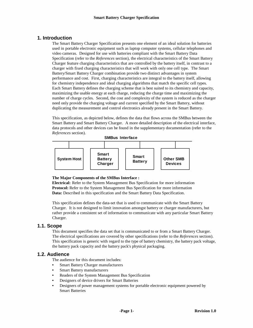
1. IntroductionThe Smart Battery Charger Specification presents one element of an ideal solution for batteriesused in portable electronic equipment such as laptop computer systems, cellular telephones andvideo cameras. Designed for use with batteries compliant with the Smart Battery DataSpecification (refer to the References section), the electrical characteristics of the Smart BatteryCharger feature charging characteristics that are controlled by the battery itself, in contrast to acharger with fixed charging characteristics that will work with only one cell type. The SmartBattery/Smart Battery Charger combination provide two distinct advantages in systemperformance and cost. First, charging characteristics are integral to the battery itself, allowingfor chemistry independence and ideal charging algorithms that match the specific cell types.Each Smart Battery defines the charging scheme that is best suited to its chemistry and capacity,maximizing the usable energy at each charge, reducing the charge time and maximizing thenumber of charge cycles. Second, the cost and complexity of the system is reduced as the chargerneed only provide the charging voltage and current specified by the Smart Battery, withoutduplicating the measurement and control electronics already present in the Smart Battery.
This specification, as depicted below, defines the data that flows across the SMBus between theSmart Battery and Smart Battery Charger. A more detailed description of the electrical interface,data protocols and other devices can be found in the supplementary documentation (refer to theReferences section).
Smart
SMBus Interface
System HostSmart
Other SMBDevicesBatteryCharger
Battery
The Major Components of the SMBus Interface :Electrical: Refer to the System Management Bus Specification for more informationProtocol: Refer to the System Management Bus Specification for more informationData: Described in this specification and the Smart Battery Data Specification.
This specification defines the data-set that is used to communicate with the Smart BatteryCharger. It is not designed to limit innovation amongst battery or charger manufacturers, butrather provide a consistent set of information to communicate with any particular Smart BatteryCharger.
1.1. ScopeThis document specifies the data set that is communicated to or from a Smart Battery Charger.The electrical specifications are covered by other specifications (refer to the References section).This specification is generic with regard to the type of battery chemistry, the battery pack voltage,the battery pack capacity and the battery pack's physical packaging.
1.2. AudienceThe audience for this document includes:• Smart Battery Charger manufacturers• Smart Battery manufacturers• Readers of the System Management Bus Specification• Designers of device drivers for Smart Batteries• Designers of power management systems for portable electronic equipment powered by
Smart Batteries

Smart Battery Charger Specification
-Page 2- Revision 1.0
2. References• System Management Bus Specification Revision 1.0, Intel Inc., February, 1995• Smart Battery Data Specification Revision 1.0 Duracell/Intel Inc., February, 1995• Smart Battery Selector Specification Revision 1.0, Duracell/Intel Inc., July, 1996
3. Definitions• Battery: One or more cells that are designed to provide electrical power.• Cell: The cell is the smallest unit in a battery. Most batteries consist of several cells
connected in series, parallel, or a series-parallel combination.• Host Controller: An intelligent entity that communicates with a Smart Battery and a Smart
Battery Charger, reading the battery’s charge requirements and controlling the batterycharger. It can reside in many places such as: an integrated part of the charger, a standalone component or part the SMBus host controller.
• Smart Battery: A battery equipped with specialized hardware that provides present state,calculated and predicted information to its System Host under software control.
• Smart Battery Charger: A battery charger that periodically communicates over the SMBuswith a Smart Battery and can alter its charging characteristics in response to informationprovided by the Smart Battery. There are two types of Smart Battery Chargers described inthis specification: Smart Battery Controlled (Level 2) and Host Controlled (Level 3).
• Smart Battery Selector: A Smart Device that controls multiple Smart Batteries in asystem. It establishes, arbitrates and maintains the power, communication and thermistorpaths between the Smart Battery, Smart Battery Charger and the System Host’s powersupply.
• Smart Device: An electronic device or module that communicates over the SMBus with theSystem Host and/or other Smart Devices. For example the back-light controller in aNotebook computer can be implemented as a Smart Device.
• SMBus: The System Management Bus is a specific implementation of an I²C-bus thatprovides data protocols, device addresses and additional electrical requirements that aredesigned to physically transport commands and information between the Smart Battery,System Host, Smart Battery Charger and other Smart Devices.
• System Host: A piece of portable electronic equipment powered by a Smart Battery. It isable to communicate with the Smart Battery and use information provided by the battery.
Smart Battery Charger Specification
-Page 3- Revision 1.0
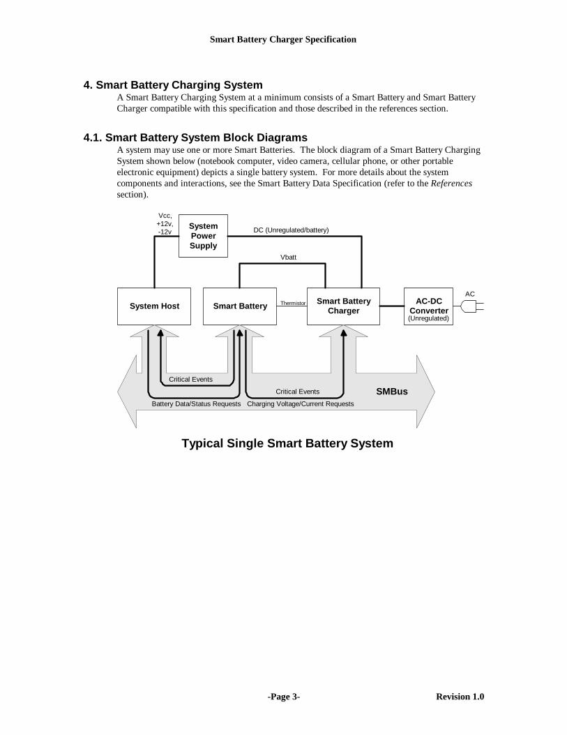
4. Smart Battery Charging SystemA Smart Battery Charging System at a minimum consists of a Smart Battery and Smart BatteryCharger compatible with this specification and those described in the references section.
4.1. Smart Battery System Block DiagramsA system may use one or more Smart Batteries. The block diagram of a Smart Battery ChargingSystem shown below (notebook computer, video camera, cellular phone, or other portableelectronic equipment) depicts a single battery system. For more details about the systemcomponents and interactions, see the Smart Battery Data Specification (refer to the Referencessection).
System Host
SystemPowerSupply
Smart BatteryChargerSmart Battery
Vbatt
Vcc,+12v,-12v
Charging Voltage/Current Requests
Critical Events
Battery Data/Status Requests
SMBusCritical Events
AC-DCConverter
DC (Unregulated/battery)
ACThermistor
Typical Single Smart Battery System
(Unregulated)

Smart Battery Charger Specification
-Page 4- Revision 1.0
Another possibility is a system that uses two or more Smart Batteries. One possible blockdiagram of such a system featuring multiple batteries is shown below. The Smart BatterySelector is used to connect batteries to either the Smart Battery Charger, the system or disconnectthem, as appropriate. For each battery, three connections must be made, power (the battery’spositive and negative terminals), the SMBus (Clock and Data) and the thermistor. Additionally,the system host must be able to query any battery in the system so it can display the state of allbatteries present in the system. For more details about the system components and interactions,see the Smart Battery Data Specification and/or the Smart Battery Selector Specification (refer tothe References section).
System Host
SystemPowerSupply
Smart BatteryCharger
Smart Battery #1
VCharge
Vcc,+12v,-12v
Critical Events
Battery Data/Status Requests SMBus
AC-DCConverter
DC (Unregulated/battery)AC
Typical Multiple Smart Battery System
(Unregulated)
Smart Battery #2
SMBus
SM
Bus
SM
Bus
Vba
tt
Vba
tt
Ther
mis
tor
Ther
mis
tor
Thermistor
Note: SB #1 powering system SB #2 charging
Smart BatterySelector
The block diagram above shows a two battery system where Battery 2 is being charged whileBattery 1 is powering the system. This configuration may be used to “condition” Battery 1;allowing it to be fully discharged prior to recharge.

Smart Battery Charger Specification
-Page 5- Revision 1.0
4.2. Smart Battery Charger TypesTwo types of Smart Battery Chargers are defined: Smart Battery Controlled (Level 2) and HostControlled (Level 3). Each has a particular set of characteristics and minimum command setwhich this document defines. All Smart Battery Chargers communicate with the Smart Batteryusing the SMBus. They differ in their ability to provide charging services to the Smart Battery.Host controlled chargers are supersets of Smart Battery Controlled chargers and as such supportall Smart Battery controlled charger commands. See Section 6 for more detailed characteristicsthe charger types.
Note: Level 1 Smart Battery Chargers were defined in the version 0.95a specification. Whilethey can correctly interpret Smart Battery end-of-charge messages minimizing over-charge, theydo not provide truly chemistry independent charging. They are no longer defined by the SmartBattery Charger specification and are explicitly not compliant with this and subsequent SmartBattery Charger specifications.
4.2.1. Smart Battery Controlled (Level 2) Smart Battery ChargerThe Smart Battery controlled or Level 2 Smart Battery Charger interprets the Smart Battery'scritical warning messages, and operates as an SMBus slave device that responds toChargingVoltage() and ChargingCurrent() messages sent to it by a Smart Battery. The chargerdynamically adjusts its output characteristics in response to the ChargingVoltage() andChargingCurrent() messages it receives from the battery. The Smart Battery is in the bestposition to tell the Smart Battery Charger how it needs to be charged. The charging algorithm inthe battery may simply request a static charge condition or may choose to periodically adjust theSmart Battery Charger's output to meet its present needs. The Smart Battery controlled SmartBattery Charger is truly chemistry independent. As a SMBus slave device only, the SmartBattery Charger is a relatively inexpensive and easy to implement device.
4.2.2. Host Controlled (Level 3) Smart Battery ChargerThe Host Controlled or Level 3 Smart Battery Charger not only interprets the Smart Battery'scritical warning messages, but is able to act as an SMBus master device. It polls the SmartBattery to determine the charging voltage and current the battery desires. The Host controlledcharger then dynamically adjusts its output to meet the battery's charging requirements. TheSmart Battery is in the best position to tell the Smart Battery Charger how it wants to be charged.Using the charging algorithm in the battery, the Host controlled charger may simply set a chargecondition once or may choose to periodically adjust the Smart Battery Charger's output to meetthe changing needs of the Smart Battery.
A Host controlled Smart Battery Charger is free to implement an alternative specialized chargingalgorithm. A Host controlled Smart Battery Charger may also interrogate the Smart Battery forany other relevant data, such as time remaining to full charge, battery temperature or other dataused to control proper charging or discharge conditioning. For example, a medical device withstricter temperature limits than the Smart Battery's self-contained charging algorithm, may use aHost controlled charger that factors in the battery's reported temperature into its chargingalgorithm.
Like the Smart Battery controlled charger, the Host controlled Smart Battery Charger is alsochemistry independent. Because it supports SMBus Master Mode, the Host controlled SmartBattery Charger is more complex, thus more expensive than a Smart Battery controlled charger.In some cases, a system designer may choose to use the system host to communicate with boththe Smart Battery and a Smart Battery controlled Smart Battery Charger to provide a hybrid Hostcontrolled functionality.
Smart Battery Charger Specification
-Page 6- Revision 1.0
4.3. Interface DefinitionThe interface is separated into two types: normal communications that are either Smart Battery-to-Smart Battery Charger or Smart Battery Charger-to-Smart Battery, and criticalcommunications that are exclusively Smart Battery-to-Smart Battery Charger. None of thecommunications require the system’s Host take any action to control charging.
An internal or external battery charger must understand the characteristics of the battery it ischarging. Today's laptops, using NiMH and NiCad batteries, apply a constant current to thebattery. End-of-charge is generally determined by monitoring the battery’s voltage and/orinternal temperature. There can be problems with this scheme; when a battery with a differentchemistry is placed in the same package, even though the voltage is the same, the chargingcharacteristics may be quite different.
A better method is to have the battery control charging: terminating charging when charging iscomplete and adjusting the charging voltage and current so they best match the battery's presentneeds. Chargers that cooperate with the battery have distinct advantages over the simple model:they provide the battery with all the power it can handle (that is, maximum safe charge) withoutovercharging, they will recognize and correctly charge batteries with different chemistries andvoltages, and they use actual measurements of battery terminal voltage and temperature, madewithin the battery case itself.
4.3.1. Typical Communications Between a Smart Battery-and-Smart Battery ChargerCommunication between the Smart Battery and the Smart Battery Charger may be initiated byeither the battery or the charger depending upon the specific implementation, but the sameinformation is exchanged between the battery and the charger, regardless of which deviceinitiated the transaction. For example, a Host Controlled charger may poll the batteryperiodically to determine the appropriate charge voltage and current, while a Smart Batterycontrolled charger must wait for the battery to initiate the data transmission. In both cases, data(charging voltage and current) is supplied by the battery to the charger.
Smart Battery to Smart Battery Charger communications are performed:• To allow the Smart Battery to instruct the Smart Battery Charger to set the appropriate
charge current and charge voltage.• To allow access to the "correct" charge algorithm for the battery.• To allow Smart Batteries to be charged as rapidly and as safely as possible.• To allow new and different battery technologies to be used in existing equipment.
4.3.2. Critical Communications from a Smart Battery to the Smart Battery ChargerA Smart Battery must have the ability to inform the Smart Battery Charger of potentiallydangerous conditions. These notifications represent a final effort on the part of the battery toinform the Smart Battery Charger and System Host that the battery is being overcharged. TheSmart Battery expects the Smart Battery Charger and/or the System Host to take the appropriatecorrective action.
Smart Battery-to-Smart Battery Charger or System Host communications are performed:• To allow the Smart Battery to instruct the Smart Battery Charger to discontinue charging
due to:♦ over charge♦ end of normal charge♦ over temperature.
• To allow the Smart Battery to instruct the Smart Battery Charger to restart charging whento:

Smart Battery Charger Specification
-Page 7- Revision 1.0
♦ the battery alarm conditions have returned to normal♦ an end of discharge cycle has occurred during battery conditioning.

Smart Battery Charger Specification
-Page 8- Revision 1.0
4.4. Error Detection and SignalingThe Smart Battery Charger supports the SMBus method for error signaling. This error system isdesigned to minimize the amount of traffic on the SMBus and the amount of code required tocommunicate with the charger.
4.4.1. Error DetectionWhen a Smart Battery Charger detects an error condition (such as an unsupported command,data unavailable, busy or bad data) it signals the master (Smart Battery or System Host) that anerror has been detected. All functions processed by the Smart Battery Charger are assumed to beerror-free unless the Smart Battery signals the master device that an error has occurred.
4.4.2. Error SignalingA Smart Battery Charger signals the SMBus master device that it has detected an unrecoverableerror by taking advantage of the SMBus requirement that an acknowledge bit must be sent by theslave after every byte is transferred. When the Smart Battery Charger fails to provide theacknowledge bit, the SMBus master device is obliged to generate a STOP condition, thus causinga premature termination of the transfer. This signals the SMBus master device that an error hasoccurred.
The Smart Battery Charger must ALWAYS acknowledge its own address. Failure to do so maycause the System Host or Smart Battery to incorrectly assume the Smart Battery Charger is NOTpresent in the system. The Smart Battery Charger may choose not to acknowledge any bytefollowing its address if it is busy or otherwise unable to respond.
Optionally, Smart Battery Chargers may support error registers that can be read by the systemhost.

Smart Battery Charger Specification
-Page 9- Revision 1.0
5. Smart Battery Charger CommandsCommunication between the Smart Battery and Smart Battery Charger may be initiated by thebattery or the charger, depending upon the specific implementation. In either case, the sameinformation is transmitted between the battery and the charger. It is important to note that thiscommunication does not require host intervention and depending upon implementation, allowsfor successful charging even when the system host is not powered or is absent.
Smart Battery controlled chargers are always slave devices and therefore all communication withthese chargers is initiated by the Smart Battery or other master device, typically the System Host.Whenever the Smart Battery's BatteryMode() CHARGER_MODE bit is cleared (default) and theSmart Battery desires to be charged and detects the presence of a Smart Battery Charger(optional), it will send the ChargingCurrent() and ChargingVoltage() values to the Smart BatteryCharger. The Smart Battery will continue broadcasting these values at whatever interval itdeems appropriate (no less than once per minute) in order to maintain correct charging. Forexample, the Smart Battery may detect the presence of a Smart Battery Charger by recognizing acharge current or voltage at the battery terminals and begin regular broadcasts to the charger.Even if no Smart Battery Charger is present, the Smart Battery may choose to broadcast to thecharger address. See Smart Battery Data Specification for details (refer to the Referencessection).
Host controlled chargers may initiate charging by interrogating the Smart Battery forChargingCurrent() and/or ChargingVoltage(). For example, this may be initiated by the presenceof a charge source, such as an A-C wall adapter, or by direct command of the system host.Further, Host controlled chargers may also operate as slave devices in the same manner as SmartBattery controlled chargers.
Whenever the Smart Battery detects a critical condition, it will become a bus master and send anAlarmWarning() message to both the Smart Battery Charger and the System Host, asappropriate, to notify them of the critical condition. The message sent by the AlarmWarning()function is similar to the message returned by the BatteryStatus() function. All Smart BatteryChargers must discontinue charging upon receipt of an AlarmWarning() message if the errorindicates that charging should be terminated. See the description of the AlarmWarning()function for a list of the alarms that should terminate charging.
The following functions are used by the Smart Battery Charger system to communicate with aSystem Host, Smart Battery and other devices connected via the SMBus. All functions include acommand and then either read or write a 2 byte word. For more details about the data structureand communication protocol, see the System Management Bus Specification (refer to theReferences section).
The Smart Battery Charger described by this specification does not use the voltage and currentscaling information contained in the Smart Battery’s SpecificationInfo(). The charger interpretsall voltage and current commands using one as the scaling factor.
In some implementations, the Smart Battery Charger may be microcontroller based and mayinclude additional functionality such as those provided by the Smart Battery Selector.

Smart Battery Charger Specification
-Page 10- Revision 1.0
The functions are described as follows:
FunctionName() 0xnn (command code)
Description:A brief description of the function.
Purpose:The purpose of the function, and an example where appropriate.
Supported by:This function must be supported by the charger level specified.
SMBus Protocol:Describes the data protocol used by the function
Input, Output or Input/Output: A description of the data supplied to or returned by thefunction.The data is described as follows:
data type: The type of data the function conveys (See Appendix B)Units: The units the data is presented inRange: The range of valid dataGranularity: See next paragraphAccuracy: How "good" is the data.
Integral to the Smart Battery/Smart Battery Charger concept is that the “measured” values, thatis, those provided by the battery, exceed the accuracy of the “regulated” values provided by thecharger. In this way, the cost of the system is kept to a minimum because there is no need toduplicate the costs associated with highly accurate analog components at both the charger and thebattery.
A Smart Battery Charger's granularity is generally defined by the resolution of its D-A. Forexample, a Smart Battery Charger that has a designed maximum regulated charge current of 4Amps will have a ChargingCurrent() granularity of 0.4% (15.6mA) for an 8-bit D-A, 0.2%(7.8mA) for a 9-bit D-A, 0.1% (3.9mA) for a 10 bit D-A and 0.05% (1.9mA) for an 11 bit D-A.
This specification requires that a monotonic D-A converter with at least 8-bits of resolution beused to meet the minimum granularity requirements for charger “regulated” values. Althoughthe granularity and accuracy values specified represent a minimum standard of performance,better performance is encouraged.
Smart Battery Charger Specification
-Page 11- Revision 1.0
5.1. Smart Battery Charger Slave Functions (battery or host-to-charger)The following functions are performed by the charger operating as an SMBus slave device. Theyare required functions for a Smart Battery Charger. Any master device, typically the SmartBattery, or the system host operating as a master, initiates these functions.
5.1.1. ChargingCurrent() (0x14)
Description:The Battery, System Host or other master device sends the desired charging rate (ma). Note: Thebattery may decide to calculate this based on its desired rate plus the system's measured powerrequirements. Note: It is incumbent upon the battery to be able to withstand considerablevariations in the charging current if the load varies rapidly because of device and bus latencies.
Purpose:The ChargingCurrent() function sets the maximum current that a Smart Battery Charger maydeliver to the Smart Battery. In combination with the ChargingVoltage() function and thebattery's internal impedance, this function determines the Smart Battery Charger's desiredoperating point. Together, these functions permit a Smart Battery Charger to dynamically adjustits charging profile (current/voltage) for optimal charge. The Smart Battery can effectively turnoff the Smart Battery Charger by returning 0 for this function. Smart Battery Chargers may beoperated as a constant voltage source above their maximum regulated current range by returninga ChargingCurrent() value of 65535.
SMBus Protocol: Write Word
Output: unsigned int -- maximum charger output current in maUnits: maRange: data range is 0 to 65,534 ma
output range is defined by the specific implementation, butnot less than 8 bits within the 16 bit field
Granularity: 0.4% (8 bits) or better, monotonicAccuracy: ±5% of twice the value the most significant bit weight or
better. It is strongly recommended that the accuracy beconsiderably better, particularly in the expected operatingrange. Note that while the absolute accuracy of the charger isrelatively low, the Smart Battery controls the charger and itmust have adequate measurement precision for the chemistryit supports. The Smart Battery can adjust its charging currentrequests based on its measurement its input current. Lessstringent requirements on the charger’s accuracy avoidsduplication of high precision elements lowering the systemcost without sacrificing performance. (see Appendix E)
Invalid Data Indication: 65,535 indicates the battery needs constant voltage atthe ChargingVoltage() value.
Note1: This is the same value as that listed in 5.2.1. In the case shown here, the value iswritten by the Smart Battery or other master device, to the Smart Battery Charger.
Note2: The Smart Battery Charger responds to current requests in one of three ways:• supply the current requested• supply the programmatic maximum current if the request is greater than its
programmatic maximum and less than 65535• supply its maximum safe current if the request is 65535

Smart Battery Charger Specification
-Page 12- Revision 1.0
Note3: The battery may return a value based on its desired charge rate plus the system'smeasured power requirements, if any. In this way, actual charge current into the batteryis controlled.
5.1.2. ChargingVoltage() (0x15)
Description:The Battery, System Host or other master device sends the desired charging voltage to the SmartBattery Charger (mv).
Purpose:The ChargingVoltage() function sets the maximum voltage that a Smart Battery Charger maydeliver to the Smart Battery. In combination with the ChargingCurrent() function and thebattery's internal impedance, this function determines the Smart Battery Charger's desiredoperating point. Together, these functions permit a Smart Battery Charger to dynamically adjustits charging profile (current/voltage) for optimal charge. The Smart Battery can effectively turnoff the Smart Battery Charger by returning a value of 0 for this function. Smart Battery Chargersmay be operated as a constant current source above their maximum regulated voltage range byreturning a ChargingVoltage() value of 65535.
SMBus Protocol: Write Word
Output: unsigned int -- charger output voltage in mvUnits: mvRange: data range is 0 to 65,534 mv
output range is defined by the specific implementation, butnot less than 8 bits within the 16 bit field
Granularity: 0.4% (8 bits) or better, monotonicAccuracy: ±5% of twice the value the most significant bit weight or
better. It is strongly recommended that the accuracy beconsiderably better, particularly in the expected operatingrange. Note that while the absolute accuracy of the charger isrelatively low, the Smart Battery controls the charger and itmust have adequate measurement precision for the chemistryit supports. The Smart Battery can adjust its charging voltagerequests based on the its charge state and terminal voltage.Less stringent requirements on the charger’s accuracy avoidsduplication of high precision elements lowering the systemcost without sacrificing performance. (see Appendix E)
Invalid Data Indication: 65,535 indicates the battery needs a constant currentat the ChargingCurrent() value.
Note1: This is the same value as that listed in 5.2.2. In the case shown, the value is written bythe Smart Battery or other master device, to the Smart Battery Charger.
Note2: The Smart Battery Charger responds to voltage requests in one of three ways:• supply the voltage requested• supply the programmatic maximum voltage if the request is greater than its
programmatic maximum and less than 65535• supply its maximum safe voltage if the request is 65535
Smart Battery Charger Specification
-Page 13- Revision 1.0
5.1.3. AlarmWarning() (0x16)
Description:The Smart Battery, acting as a bus master device, sends the AlarmWarning() message to theSmart Battery Charger and/or the System Host, to notify them that the one or more alarmconditions exist. Alarm indications are encoded as bit fields in the Battery's Status register,which is then sent to the System Host and/or Smart Battery Charger by this function. The batteryAlarmWarning() message sets the corresponding bits in the charger's AlarmWarning(). Note thatthe SMBus specification requires that the command code for this function be the same as theSmart Battery's address. All alarm conditions are sent to the System Host but only those alarmsrelating to charging are sent to the Smart Battery Charger.
Purpose:The AlarmWarning() sent by the Smart Battery may be used by the System Host to notify the userabout Alarms generated by the Smart Battery. The System Host's power management system andthe Smart Battery Charger are responsible for processing the alarm and taking appropriateaction. The Smart Battery Charger will use the information to properly charge the system. Forexample, if the OVER_TEMP_ALARM bit is set, it is expected that the Smart Battery Chargerwill cease charging the battery to prevent damage. Although all the AlarmWarning() bits arepre-assigned, only 0x8000, 0x4000, 0x1000 and 0x0800 are used by the Smart Battery Charger.Charging will be terminated immediately when any bit or combination of bits in the upper nibbleare set, including the reserved bit. An 0x0800 may be used to signal that the charger may berestarted after a battery conditioning cycle has been completed.
SMBus Protocol: Write Word
Output: unsigned int - Status Register with alarm conditions bit mapped:* * * * * * Alarm Bits * * * * *0x8000 OVER_CHARGED_ALARM0x4000 TERMINATE_CHARGE_ALARM0x2000 reserved0x1000 OVER_TEMP_ALARM0x0800 TERMINATE_DISCHARGE_ALARM0x0400 reserved0x0200 REMAINING_CAPACITY_ALARM0x0100 REMAINING_TIME_ALARM* * * * * * Status Bits * * * * *0x0080 INITIALIZED0x0040 DISCHARGING0x0020 FULLY_CHARGED0x0010 FULLY_DISCHARGED* * * * * * Error Code * * * * *0x0000-0x000f All bits set high prior to AlarmWarning() transmission.
NOTE: Alarm Bits 0x0200 and 0x0100 cause the AlarmWarning() to be sent only to the SystemHost. All other Alarm Bits cause the AlarmWarning() to be sent to both the System Host and theSmart Battery Charger. See Smart Battery Data Specification for details (refer to the Referencessection).

Smart Battery Charger Specification
-Page 14- Revision 1.0
5.1.4. ChargerMode() (0x12)
Description:The SMBus system host uses this command to set the various charger modes. The default valuesare set to allow a Smart Battery and the Smart Charger to work in concert without requiring anSMBus host.
Purpose:Allows the System Host to configure the charger and change the default modes. This is a writeonly function, but the value of the "mode" bits: INHIBIT_CHARGE and ENABLE_POLLINGmay be determined using the ChargerStatus() function.
SMBus Protocol: Write Word
Input: unsigned int - bit mapped - see belowUnits: not applicableRange: not applicableGranularity not applicableAccuracy: not applicable
Field Bits Used Format Allowable Values
INHIBIT_CHARGE 0 bit flag 0 - enable charging (power-on default)1 - inhibit charging
ENABLE_POLLING 1 bit flag 0 - disable polling (power-on default for Smart Batterycontrolled chargers)1 - enable polling (power-on default for Host controlledchargers)
POR_RESET 2 bit flag 0 - mode unchanged (default)1 - set charger to power-on defaults
RESET_TO_ZERO 3 bit flag 0 - charging values unchanged (default)1 - set charging values to zero
Reserved 4...15
The INHIBIT_CHARGE bit allows charging to be inhibited without changing theChargingCurrent() and ChargingVoltage() values. This bit may be set only by the System Hostwhile a battery is charging to inhibit charge. The Smart Battery is not allowed to write to thisbit. The charging may be resumed by clearing the bit. This bit is automatically cleared whenpower is re-applied or when a battery is re-inserted.
The ENABLE_POLLING bit enables the polling feature of Host controlled chargers. This bit isset at power on for Host controlled chargers otherwise is cleared for Smart Battery controlledchargers.
The POR_RESET bit sets the Smart Battery Charger to its power-on default conditions.
The RESET_TO_ZERO bit sets the ChargingCurrent() and ChargingVoltage() values to zero.This function ALWAYS clears the ChargingVoltage() and ChargingCurrent() values to zeroeven if the INHIBIT_CHARGE bit is set. Refer to Appendix F for further information.
Writing to any mode bit will cause the appropriate actions to take place, but will not set the bits.The ChargerMode() bits are undefined when read, as they are defined only for write.
Smart Battery Charger Specification
-Page 15- Revision 1.0
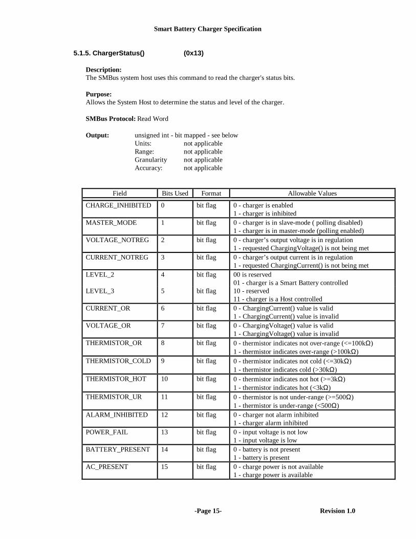
5.1.5. ChargerStatus() (0x13)
Description:The SMBus system host uses this command to read the charger's status bits.
Purpose:Allows the System Host to determine the status and level of the charger.
SMBus Protocol: Read Word
Output: unsigned int - bit mapped - see belowUnits: not applicableRange: not applicableGranularity not applicableAccuracy: not applicable
Field Bits Used Format Allowable Values
CHARGE_INHIBITED 0 bit flag 0 - charger is enabled1 - charger is inhibited
MASTER_MODE 1 bit flag 0 - charger is in slave-mode ( polling disabled)1 - charger is in master-mode (polling enabled)
VOLTAGE_NOTREG 2 bit flag 0 - charger’s output voltage is in regulation1 - requested ChargingVoltage() is not being met
CURRENT_NOTREG 3 bit flag 0 - charger’s output current is in regulation1 - requested ChargingCurrent() is not being met
LEVEL_2 4 bit flag 00 is reserved01 - charger is a Smart Battery controlled
LEVEL_3 5 bit flag 10 - reserved11 - charger is a Host controlled
CURRENT_OR 6 bit flag 0 - ChargingCurrent() value is valid1 - ChargingCurrent() value is invalid
VOLTAGE_OR 7 bit flag 0 - ChargingVoltage() value is valid1 - ChargingVoltage() value is invalid
THERMISTOR_OR 8 bit flag 0 - thermistor indicates not over-range (<=100kΩ)1 - thermistor indicates over-range (>100kΩ)
THERMISTOR_COLD 9 bit flag 0 - thermistor indicates not cold (<=30kΩ)1 - thermistor indicates cold (>30kΩ)
THERMISTOR_HOT 10 bit flag 0 - thermistor indicates not hot (>=3kΩ)1 - thermistor indicates hot (<3kΩ)
THERMISTOR_UR 11 bit flag 0 - thermistor is not under-range (>=500Ω)1 - thermistor is under-range (<500Ω)
ALARM_INHIBITED 12 bit flag 0 - charger not alarm inhibited1 - charger alarm inhibited
POWER_FAIL 13 bit flag 0 - input voltage is not low1 - input voltage is low
BATTERY_PRESENT 14 bit flag 0 - battery is not present1 - battery is present
AC_PRESENT 15 bit flag 0 - charge power is not available1 - charge power is available
Smart Battery Charger Specification
-Page 16- Revision 1.0
CHARGE_INHIBITED bit reflects the status of the charger set by the INHIBIT_CHARGE bit(see 5.1.4).
MASTER_MODE bit is set if the charger is a Host controlled charger with theENABLE_POLLING bit of ChargerMode() set. Smart Battery controlled chargers must return 0.
VOLTAGE_NOTREG bit is set when the charger detects that the requested voltage in theChargingVoltage() register is not in regulation. This bit is cleared when the charging voltage isin regulation. This bit is not defined when the charger is disabled.
CURRENT_NOTREG bit is set when the charger detects that the requested current in theChargingCurrent() register is not in regulation. This bit is cleared when the charging current isin regulation. This bit is not defined when the charger is disabled.
LEVEL_2 bit is set and the LEVEL_3 bit is cleared if the charger is Smart Battery controlled.This bit will always be set.
LEVEL_3 bit is set and the Level_2 bit is set if the charger is capable of operating as a Hostcontrolled charger. A LEVEL_3 charger must be able to operate as a LEVEL_2 charger whenthe ENABLE_POLLING bit is cleared.
CURRENT_OR bit is set only when the ChargingCurrent() is set to a value greater than thecurrent range of the charger. This bit may be used in conjunction with the INHIBIT_CHARGEbit of ChargerMode() and ChargingCurrent() to determine the current capability of the charger.
VOLTAGE_OR bit is set only when the ChargingVoltage() is set to a value greater than thevoltage range of the charger. This bit may be used in conjunction with the INHIBIT_CHARGEbit of ChargerMode() and ChargingVoltage() to determine the voltage capability of the charger.
THERMISTOR_OR bit is set only when the thermistor value is > 100kΩ. This indicates that thethermistor is open.
THERMISTOR_COLD bit is set only when the thermistor value is > 30kΩ. The thermistorindicates a cold battery.
THERMISTOR_HOT bit is set only when the thermistor value is < 3kΩ.
THERMISTOR_UR bit is set only when the thermistor value is < 500Ω.
Note: Multiple bits may be set depending on the value of the thermistor (e.g., a thermistor that is450 ohms will cause both the THERMISTOR_HOT and the THERMISTOR_UR bits to be set).The thermistor may be replaced by fixed value resistors in battery packs that do not require thethermistor as a secondary fail-safe indicator. In this case, it is the responsibility of the batterypack to manipulate the resistance to obtain correct charger behavior (see 6.1.1).
ALARM_INHIBITED bit is set if a valid AlarmWarning() message has been received andcharging is inhibited as a result. This bit is cleared if both ChargingVoltage() andChargingCurrent() are re-written to the charger, power is removed, or if a battery is removed.
POWER_FAIL bit is set if the input to the power fail comparator is below the comparator setthreshold. This comparator input generally will be used to monitor the battery voltage forcatastrophic faults.
BATTERY_PRESENT is set if a battery is present otherwise it is cleared. Any method may beused to determine if a battery is present, but generally this bit will be the logical inverse ofTHERMISTOR_OR.

Smart Battery Charger Specification
-Page 17- Revision 1.0
AC_PRESENT is set if a source of power for charging is available otherwise it is cleared.
5.1.6. ChargerSpecInfo() (0x11)
Description:The SMBus system host uses this command to read the charger's extended status bits.
Purpose:Allows the System Host to determine the specification revision the charger supports as well asother extended status information.
SMBus Protocol: Read Word
Output: unsigned int - bit mapped - see belowUnits: not applicableRange: not applicableGranularity not applicableAccuracy: not applicable
Field Bits Used Format Allowable Values
CHARGER_SPEC 0…3 bit flag The CHARGER_SPEC reports the version of the SmartBattery Charger specification the charger it supports:0001 - Version 1.0.All other codes reserved.
SELECTOR_SUPPORT 4 bit flag 0 - charger does not support the optional Smart BatterySelector commands1 - charger supports the optional Smart Battery Selectorcommands
reserved 5…15 bit flag These bits are reserved and will return zero.
CHARGER_SPEC bits indicate which version of the Smart Battery Charger specification thecharger supports. For Revision 1.0 of the Smart Battery Charger specification, the value will be1.
SELECTOR_SUPPORT bit is set if the charger supports the optional Smart Battery Selectorfunctionality.

Smart Battery Charger Specification
-Page 18- Revision 1.0
5.2. Smart Battery Charger Master Functions (charger-to-battery)A Host controlled charger, when acting as master, has the ability to query the Smart Battery todetermine the Smart Battery's charging requirements. In this case, the Host controlled chargershould set the Battery Mode() CHARGER_MODE bit to suppress the regular broadcast ofcharging data from the Smart Battery. The Host controlled charger may poll the battery usingthe Smart Battery’s ChargingVoltage() and ChargingCurrent() functions to determine thecharging requirements. The Smart Battery Charger will continue requesting these values atwhatever interval it deems appropriate in order to maintain correct charging.
Notes:1. In order to ensure proper charging of ALL battery chemistries, it is suggested that a
minimum polling frequency of once per minute be used.2. While operating as a Host controlled charger, the Smart Battery’s SpecificationInfo() scaling
information may be used. However, when operating as a LEVEL_2 or a LEVEL_3, thecharger default is NOT to use the voltage and current scaling information contained in theSmart Battery’s SpecificationInfo(). Additionally, the charger is expected to return to thisdefault state whenever the ENABLE_POLLING bit is cleared or the charger is reset.
5.2.1. ChargingCurrent() (0x14)
Description:The Smart Battery Charger makes a request to the Smart Battery to get its desired charging rate(ma).
Purpose:The charger uses the ChargingCurrent() function to request the charging current from theBattery. The response is used by the charger to set the maximum current that a Smart BatteryCharger may deliver to the Smart Battery. In combination with the response to theChargingVoltage() function and the battery's internal impedance, this function determines theSmart Battery Charger's desired operating point. Together, these functions permit a SmartBattery Charger to dynamically adjust its charging profile (current/voltage) for optimal charge.The Smart Battery can effectively turn off the Smart Battery Charger by returning 0 for thisfunction. Smart Battery Chargers may be operated as a constant voltage source above theirmaximum regulated current range by returning a ChargingCurrent() value of 65535.
Supported by: Host controlled charger
SMBus Protocol: Read Word
Output: unsigned int -- maximum charger output current in maUnits: maRange: data range is 0 to 65,534 ma
output range is defined by the specific implementation, butnot less than 8 bits within the 16 bit field
Granularity: 0.4% (8 bits) or better, monotonicAccuracy: ±5% of twice the value the most significant bit weight or
better. It is strongly recommended that the accuracy beconsiderably better, particularly in the expected operatingrange. Note that while the absolute accuracy of the charger isrelatively low, the Smart Battery controls the charger and itmust have adequate measurement precision for the chemistryit supports. The Smart Battery can adjust its charging currentrequests based on its measurement its input current. Less

Smart Battery Charger Specification
-Page 19- Revision 1.0
stringent requirements on the charger’s accuracy avoidsduplication of high precision elements lowering the systemcost without sacrificing performance. (see Appendix E)
Invalid Data Indication: 65,535 indicates the battery needs constant voltage atthe ChargingVoltage() value.
Note1: This is the same value as that listed in 5.1.1. In the case shown here, the value is readby the Smart Battery Charger from the Smart Battery.
Note2: The Smart Battery Charger responds to the current request in one of three ways:• supply the current requested• supply the programmatic maximum current if the request is greater than its
programmatic maximum and less than 65535• supply its maximum safe current if the request is 65535
Note3: The battery may return a value based on its desired charge rate plus the system'smeasured power requirements, if any. In this way, actual charge current into the batteryis controlled.

Smart Battery Charger Specification
-Page 20- Revision 1.0
5.2.2. ChargingVoltage() (0x15)
Description:The Smart Battery Charger requests the desired charging voltage from the Smart Battery (mv).
Purpose:The ChargingVoltage() function sets the maximum voltage that a Smart Battery Charger maydeliver to the Smart Battery. In combination with the ChargingCurrent() function and thebattery's internal impedance, this function determines the Smart Battery Charger's desiredoperating point. Together, these functions permit a Smart Battery Charger to dynamically adjustits charging profile (current/voltage) for optimal charge. The Smart Battery can effectively turnoff the Smart Battery Charger by returning a value of 0 for this function. Smart Battery Chargersmay be operated as a constant current source above their maximum regulated voltage range byreturning a ChargingVoltage() value of 65535
Supported by: Host controlled
SMBus Protocol: Read Word
Output: unsigned int -- charger output voltage in mvUnits: mvRange: data range is 0 to 65,534 mv
output range is defined by the specific implementation, butnot less than 8 bits within the 16 bit field
Granularity: 0.4% (8 bits) or better, monotonicAccuracy: ±5% of twice the value the most significant bit weight or
better. It is strongly recommended that the accuracy beconsiderably better, particularly in the expected operatingrange. Note that while the absolute accuracy of the charger isrelatively low, the Smart Battery controls the charger and itmust have adequate measurement precision for the chemistryit supports. The Smart Battery can adjust its charging voltagerequests based on the its charge state and terminal voltage.Less stringent requirements on the charger’s accuracy avoidsduplication of high precision elements lowering the systemcost without sacrificing performance. (see Appendix E)
Invalid Data Indication: 65,535 indicates the battery needs a constant currentat the ChargingCurrent() value.
Note1: This is the same value as that listed in 5.1.2. In the case shown here, the value is readfrom the Smart Battery by the Smart Battery Charger.
Note2: The Smart Battery Charger responds to voltage requests in one of three ways:• supply the voltage requested• supply the programmatic maximum voltage if the request is greater than its
programmatic maximum and less than 65535• supply its maximum safe voltage if the request is 65535

Smart Battery Charger Specification
-Page 21- Revision 1.0
6. Smart Battery Charger CharacteristicsSmart Battery Chargers are differentiated by their type (see Smart Battery Charger types in thisdocument). Each type has certain characteristics and supports certain functions. This sectiondescribes the characteristics and functions all chargers have in common as well as the those thatare type specific.
6.1. Common Smart Battery Charger CharacteristicsAll Smart Battery Chargers have the following capabilities, characteristics and options incommon.
6.1.1. Thermistor RangesThe Smart Battery Charger’s capabilities are altered by the value of the thermistor. As a requiredsafety feature, the charger must NOT charge a battery when it senses the resistance between thethermistor pin and ground to be in the range between 500 and 3k ohms. A thermistor in a NiMHbattery would enter this range if it got too hot; the thermistor (resistor) in a Li-ion battery couldbe set to this range in an emergency condition. The valid ranges a thermistor may be in aresummarized below along with the charger’s capabilities for the range.
Thermistor Charger StatusBits
Description Wake-upcharge
Responsetochargingrequests
Notes
0 to 500Ω THERM_UR,THERM_HOT
under-range allowed forinitial time-out period
allowed Charger can “wake-up”charge for time-outperiod; controlledcharge allowed.
500 to 3kΩ THERM_HOT hot not allowed notallowed
Fail-safe chargetermination -- chargermust not supply current
3k to 30kΩ (none) normalrange
allowedindefinitely
allowed Charger can “wake-up”charge indefinitely;controlled chargeallowed.
30k to 100kΩ THERM_COLD cold allowed forinitial time-out period
allowed Charger can “wake-up”charge for time-outperiod only.
Above 100kΩ THERM_OR,THERM_COLD
over-range not allowed notallowed
Can be used as batterydetect; charger does notsupply current.
6.1.2. Smart Battery Charger Time-out PeriodThe Smart Battery Charger detects that it has lost communication when it does not receivecharging messages in a timely manner. The Smart Battery Charger is required to immediatelystop charging the battery at this time. The Smart Battery Charger’s time-out period is nominally175seconds, ±35 seconds (e.g., in the range of 140 - 210 seconds). The time-out period is resetwhen a power-on reset occurs, a battery is inserted and/or when new ChargingVoltage() andChargingCurrent() commands are received.

Smart Battery Charger Specification
-Page 22- Revision 1.0
6.1.3. Smart Battery Charger Wakeup Charge CurrentSmart Battery Chargers are allowed to apply a wake-up current to the battery under someconditions defined in the Smart Battery Charger Start-up section. A charger is allowed to supplythis charge to the battery at the charger’s maximum voltage and up to 100 ma.
6.1.4. Charger Brown-Out ConditionsSituations may arise where the system attempts to charge a battery while the system is also beingpowered from the AC power supply. In these cases, the charger may not draw so much powerthat the system’s power source is compromised. The charger can, at its option, choose to chargethe battery at a lower rate automatically or abort charging entirely. The Smart Battery Chargerwill report when it lowers its output by setting the ChargerStatus() register’sVOLTAGE_NOTREG and CURRENT_NOTREG bits as appropriate.
6.1.5. Smart Battery Charger Leakage CurrentA leakage current may flow between the Smart Battery and the Smart Battery Charger at timeswhen no current flow is expected (e.g. programmed zero charge current, thermistor valueindicates no charging allowed, no input power to the charger). Smart Battery Chargermanufacturers are expected to minimize leakage current to prevent unintended over-charging orunintended low-rate discharge which may result in shortened battery life.
6.1.6. “Float” VoltageA Smart Battery Charger is allowed to output an arbitrary float voltage. The float voltage refersto the voltage output of the charger with no battery connected. There may be a desire to designthe system to present a voltage on its terminals to minimize contact arcing when a battery isplugged in. When the charger detects no battery present in the system, it may default to anoutput of 0 to its full-range voltage and up to 10mA current.
6.1.7. Smart Battery Charger Start-UpUpon start-up or at any other power-on condition (e.g., after POR_RESET has been set), thecharger is allowed to supply “wake-up” charge to the battery when the following conditions aresatisfied: AC power is present, a battery is present, the thermistor value is determined to begreater than 3k ohms or less than 500 ohms and the INHIBIT_CHARGE bit is not set. Once thetime-out period expires, the charger can optionally continue to “wake-up” charge only if thebattery’s thermistor is in the range of 3K to 30K ohms.
Some battery packs may use a fixed resistor with a value < 500 ohms in place of the thermistor toindicate that they do not want the “wake-up” charge continued past the normal time-out period.
Some possible startup system scenarios:• Constant current (e.g., NiMH) smart battery, intelligence “awake”, the battery:
• Sends both a ChargingCurrent() and ChargingVoltage() command to initiatecharging.
• Sends a ChargingCurrent() or ChargingVoltage() or both to adjust the chargingrate.
• When full, sends AlarmWarning() message, a POR_RESET, a zeroChargingCurrent() or zero ChargingVoltage() to abort charging
• Constant current smart battery, intelligence “asleep”, the battery:• Could take the “wake-up” period of charging to raise its voltage enough for the
intelligence to wake up or may expect wakeup charging to continue indefinitely aslong as the thermistor is in the “normal range”..
• Constant voltage (e.g., Li-ion) smart battery, intelligence “awake”, the battery:• Sends an AlarmWarning() message asking the charger to stop charging
Smart Battery Charger Specification
-Page 23- Revision 1.0
• Sends ChargingCurrent() and ChargingVoltage() commands requesting constantvoltage charging.
• Constant voltage smart battery, intelligence “asleep” (also implies that a deep-dischargeprotection FET is open-circuited as well)
• The voltage at the terminals of the battery pack should be enough to wake up thebattery’s microcontroller, which then sends charging voltage and current messagesto the charger and re-enables its protection device.
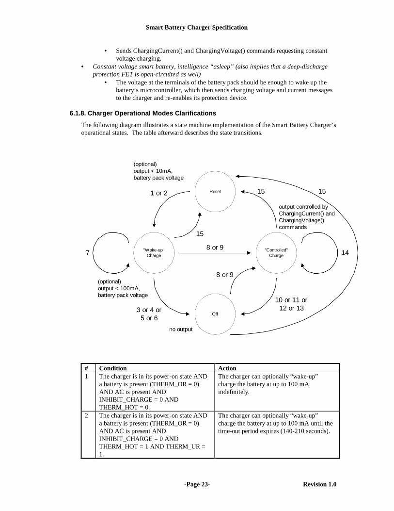
6.1.8. Charger Operational Modes Clarifications
The following diagram illustrates a state machine implementation of the Smart Battery Charger’soperational states. The table afterward describes the state transitions.
Reset
"Wake-up"Charge
Off
"Controlled"Charge
8 or 9
78 or 9
1 or 2
3 or 4 or5 or 6
15 15
14
15
10 or 11 or12 or 13
(optional)output < 10mA,battery pack voltage
(optional)output < 100mA,battery pack voltage
no output
output controlled byChargingCurrent() andChargingVoltage()commands
# Condition Action1 The charger is in its power-on state AND
a battery is present (THERM_OR = 0)AND AC is present ANDINHIBIT_CHARGE = 0 ANDTHERM_HOT = 0.
The charger can optionally “wake-up”charge the battery at up to 100 mAindefinitely.
2 The charger is in its power-on state ANDa battery is present (THERM_OR = 0)AND AC is present ANDINHIBIT_CHARGE = 0 ANDTHERM_HOT = 1 AND THERM_UR =1.
The charger can optionally “wake-up”charge the battery at up to 100 mA until thetime-out period expires (140-210 seconds).
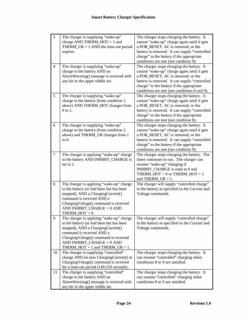
Smart Battery Charger Specification
-Page 24- Revision 1.0
3 The charger is supplying “wake-up”charge AND THERM_HOT = 1 andTHERM_UR = 1 AND the time-out periodexpires.
The charger stops charging the battery. Itcannot “wake-up” charge again until it getsa POR_RESET, AC is removed, or thebattery is removed. It can supply “controlledcharge” to the battery if the appropriateconditions are met (see condition 9).
4 The charger is supplying “wake-up”charge to the battery AND anAlarmWarning() message is received withany bit in the upper nibble set.
The charger stops charging the battery. Itcannot “wake-up” charge again until it getsa POR_RESET, AC is removed, or thebattery is removed. It can supply “controlledcharge” to the battery if the appropriateconditions are met (see conditions 8 and 9).
5 The charger is supplying “wake-up”charge to the battery (from condition 1above) AND THERM_HOT changes from0 to 1.
The charger stops charging the battery. Itcannot “wake-up” charge again until it getsa POR_RESET, AC is removed, or thebattery is removed. It can supply “controlledcharge” to the battery if the appropriateconditions are met (see condition 8).
6 The charger is supplying “wake-up”charge to the battery (from condition 2above) and THERM_UR changes from 1to 0.
The charger stops charging the battery. Itcannot “wake-up” charge again until it getsa POR_RESET, AC is removed, or thebattery is removed. It can supply “controlledcharge” to the battery if the appropriateconditions are met (see condition 9).
7 The charger is applying “wake-up” chargeto the battery AND INHIBIT_CHARGE isset to 1.
The charger stops charging the battery. Thetimer continues to run. The charger canresume “wake-up” charging ifINHIBIT_CHARGE is reset to 0 andTHERM_HOT = 0 or THERM_HOT = 1and THERM_UR = 1.
8 The charger is applying “wake-up” chargeto the battery (or had been but has beenstopped), AND a ChargingCurrent()command is received AND aChargingVoltage() command is receivedAND INHIBIT_CHARGE = 0 ANDTHERM_HOT = 0.
The charger will supply “controlled charge”to the battery as specified in the Current andVoltage commands.
9 The charger is applying “wake-up” chargeto the battery (or had been but has beenstopped), AND a ChargingCurrent()command is received AND aChargingVoltage() command is receivedAND INHIBIT_CHARGE = 0 ANDTHERM_HOT = 1 and THERM_UR = 1.
The charger will supply “controlled charge”to the battery as specified in the Current andVoltage commands.
10 The charger is supplying “controlled”charge AND no new ChargingCurrent() orChargingVoltage() command is receivedfor a time-out period (140-210 seconds)..
The charger stops charging the battery. Itcan resume “controlled” charging whenconditions 8 or 9 are satisfied.
11 The charger is supplying “controlled”charge to the battery AND anAlarmWarning() message is received withany bit in the upper nibble set.
The charger stops charging the battery. Itcan resume “controlled” charging whenconditions 8 or 9 are satisfied.

Smart Battery Charger Specification
-Page 25- Revision 1.0
12 The charger is supplying “controlled”charge to the battery (from condition 8above) AND THERM_HOT changes from0 to 1.
The charger stops charging the battery. Itcan resume “controlled” charging whencondition 8 is satisfied.
13 The charger is supplying “controlled”charge to the battery (from condition 9above) AND THERM_UR changes from 1to 0.
The charger stops charging the battery. Itcan resume “controlled” charging whencondition 9 is satisfied.
14 The charger is supplying “controlled”charge to the battery andINHIBIT_CHARGE is set to 1.
The charger stops charging the battery, butcontinues to accept new ChargingCurrent()and ChargingVoltage() commands,continues to monitor the battery thermistorinput, and continues to track thecommunications time-out. It can resumecharging the battery if INHIBIT_CHARGEis cleared to 0, possibly at difference currentand voltage is new commands have beensent in the interim.
15 The charger is in any state and it detectsno battery present OR AC not present ORa 1 is written to POR_RESET.
The charger returns to its power-on resetdefault state.
6.1.9. Optional Smart Battery Charger Registers for Selector SupportTo support implementations of a Smart Battery Charger and Smart Battery Selector combined inthe same component, optional charger command codes have been defined. These codes areoptional and only used by charger components which also include selector functionality. Theirpresence is indicated by the SELECTOR_SUPPORT bit in the ChargerSpecInfo() function.
When implemented, the Smart Battery Charger’s SelectorState(), SelectorPresets() andSelectorInfo() functions match the corresponding functions described in the Smart BatterySelector Specification. The mapping of the Smart Battery Selector functions into the SmartBattery Charger’s command codes may be accomplished by OR’ing the desired Smart BatterySelector command code with 0x20 and then sending it to the Smart Battery Charger’s SMBusaddress. Therefore, for a Smart Battery Charger / Selector component, the function code forSelectorState() is 0x21, for SelectorPresets(), 0x22 and for SelectorInfo(), 0x24. The SmartBattery Charger’s defined optional manufacturer’s extended commands remain located in therange of 0x3c-3f and this area is shared by both the charger and selector in a dual-functioncomponent.
6.1.10. Optional Charger Interrupt MechanismSmart Battery Chargers may have an optional interrupt mechanism to indicate to the system thata change in its status has taken place, for example, battery insertion or removal or AC present.While this mechanism is optional, its inclusion is highly recommended:• For single-battery systems which do not implement a Smart Battery Selector to indicate
changes in the system’s power status.• For multiple battery systems as a way to notify the Smart Battery Selector that it may
automatically charge the “next” battery.
6.1.11. Battery Internal Charge ControlChargingCurrent() and ChargingVoltage() requests from the battery may be used to define acharging “envelope” within which a battery may internally charge itself. For example, a battery

Smart Battery Charger Specification
-Page 26- Revision 1.0
which pulse charges itself with the full requested current and voltage from the charger for 80% ofthe time, and takes no power during the remaining 20% of the time while the battery “rests”.
6.2. Smart Battery Controlled Smart Battery Charger Characteristics
6.2.1. Required CommandsAlarmWarning()ChargingCurrent()ChargingVoltage()ChargerSpecInfo()ChargerMode()ChargerStatus()Note that a charger that does not support all of the commands required of a Host controlledcharger may contain some or most of the functionality of a Host controlled charger. Forexample, a Smart Battery controlled charger may support the a modified ability to poll thebattery. The strict definitions of charger types are not intended to preclude such a device, only toensure that a consistent means of determining charger type exists.
6.2.2. Charge InitiationSmart Battery controlled chargers may initiate charge:• upon insertion of a battery• when charge power becomes available• when ChargingVoltage() and ChargingCurrent() are both set to non-zero values• when the AlarmWarning() is written without critical error bits set.Other methods may be used to determine that charging may be (re)initiated. Charging is notinitiated if the thermistor is out of a valid range (see below), if the AlarmWarning() has criticalerror bits set or when either ChargingCurrent() or ChargingVoltage() are set to zero. Voltageand current may default at power-on to the expected open circuit battery voltage and a current≤10mA.
6.2.3. Charge TerminationSmart Battery controlled chargers will discontinue charging:• when AlarmWarning() is written with critical error bits set• if either ChargingCurrent() or ChargingVoltage() are set to zero• when the thermistor is out of a valid range (see below).Additional methods of charge termination are allowed.
6.2.4. Charge Current and VoltageThe maximum charging current and voltage of the Smart Battery controlled charger isdetermined by the manufacturer and is programmable through the ChargingCurrent() andChargingVoltage() commands. Default values for these may be zero or any non-zero rangedetermined to be safe for any chemistry (100mA or less). Non-zero default values, if used, mustonly be enabled when the thermistor is greater than or equal to 3kΩ and less than 30kΩ(thermistor bits not set). The default charge current and voltage must not be persistent; any newvalue of ChargingCurrrent() or ChargingVoltage() must over-write any default values.

Smart Battery Charger Specification
-Page 27- Revision 1.0
6.3. Host controlled Smart Battery Charger Characteristics
6.3.1. Required CommandsAlarmWarning()ChargingCurrent()ChargingVoltage()ChargerSpecInfo()ChargerMode()ChargerStatus()Note that a Host controlled charger supports all the commands of a Smart Battery controlledcharger and differs only in the ability to become a SMBus master device and initiate chargingdirectly. When set to the slave device mode by the ENABLE_POLLING bit not set, the Level 3charger behaves in all respects as a Level 2 charger.
6.3.2. Charge InitiationHost controlled chargers may initiate charge under the same conditions as Smart Batterycontrolled chargers and further have the ability to initiate charging under program control.When a Host controlled charger initiates polling and therefore charging, it is suggested that theHost controlled charger disable the automatic broadcasts of the battery by setting Battery ModeCHARGER_MODE bit. See the Smart Battery Data Specification for details (refer to theReferences section).
6.3.3. Charge TerminationLike the Smart Battery controlled charger, Host controlled chargers will discontinue chargingwhen an AlarmWarning() is written with critical error bits set, if either ChargingCurrent() orChargingVoltage() are set to zero, or when the thermistor is out of a valid range (see below).Additional methods of charge termination are allowed.
6.3.4. Charge Current and VoltageThe maximum charging current and voltage of the Host controlled charger is determined by themanufacturer and is programmable through the ChargingCurrent() and ChargingVoltage()commands. Default values for these may be zero or any non-zero range determined to be safe forany chemistry. Non-zero default values, when used, must only be enabled when the thermistor isgreater than or equal to 3kΩ or less than 30kΩ (thermistor bits not set). The default chargecurrent and voltage must not be persistent; any new value of ChargingCurrrent() orChargingVoltage() must over-write any default values.

Smart Battery Charger Specification
-Page 28- Revision 1.0
Appendix A The Smart Battery Charger command set in tabular formThe following tables summarize the charger commands by: the function name, command code, access(r,w), data type and applicability. For a battery charger to be recognized as a Smart Battery Charger, itmust support all the functions described by this specification for its level of implementation. The batterycharger, in the master mode, uses the listed functions to request charging information from the SmartBattery. Included in these tables are four optional command codes reserved for additional manufacturerspecific functions. In order to preserve compatibility, these optional functions may in no way effect theSmart Battery Charger’s conformance to this specification.
Battery Charger Slave Functions
Function Code Access Data ApplicabilitySmart Battery and
Host controlledchargers
ChargerSpecInfo 0x11 r bit flags requiredChargerMode 0x12 w bit flags requiredChargerStatus 0x13 r bit flags requiredChargingCurrent 0x14 w ma requiredChargingVoltage 0x15 w mV requiredAlarmWarning 0x16 w bit flags requiredSelectorState 0x21 r bit flags optionalSelectorPresets 0x22 w bit flags optionalSelectorInfo 0x24 r bit flags optionalOptionalMfgFunction4 0x3c r/w word optionalOptionalMfgFunction3 0x3d r/w word optionalOptionalMfgFunction2 0x3e r/w word optionalOptionalMfgFunction1 0x3f r/w word optional
Battery Charger Master Functions
Function Code Access Data ApplicabilityHost controlled
chargersBatteryMode 0x03 w/r CHARGER_MODE bit requiredChargingCurrent 0x14 r ma requiredChargingVoltage 0x15 r mV required
Notes:• All unused command codes are reserved.• The upper two bits of all command codes are specifically reserved for future use to optionally address
multiple batteries/chargers.

Smart Battery Charger Specification
-Page 29- Revision 1.0
Appendix B Smart Battery System Safety FeaturesSafety is a primary design goal in the Smart Battery System specifications. The central conceptbehind the Smart Battery specifications is locating the primary intelligence of the system insidethe battery pack itself, thus enabling the system to be much more accurate in measurement ofbattery parameters such as remaining capacity and design voltage, and also allowing thecharging algorithm and parameters to be tuned to the battery pack’s specific chemistry. Byrelying on the battery pack’s intelligence, a properly designed Smart Battery system will safelycharge and discharge any expected battery chemistry.
Protection against high rates of discharge is well understood by the battery industry and easilyguarded against in battery pack design through the use of safety devices such as fuses. However,protection from an over zealous charger is more difficult requiring tight coupling between thecharger and battery. The Smart Battery system defines a standard set of messages as well as anindependent means for the battery to terminate charge. Correct operation of the charger is key tomaintaining safe operation.
This section will review the safety features contained in the Smart Battery specifications.Particular attention will be focused on the following operating modes: , “Wake-up” Charging“Controlled” Charging, and Discharging.
“Wake-up” ChargingIt is possible for a battery pack to be so depleted that its built-in intelligence will not have enoughpower to operate. Therefore, the Smart Battery System specifications allow a charger to applysome small amount of charge (< 100mA at the battery pack voltage) to a battery when it is firstconnected so that it can receive enough power to wake up and communicate. This “wake-up”charge may not begin if the thermistor is not in the valid range, and will be terminated when thebattery sends a critical message to the charger, or the thermistor moves out of the valid range, or(depending on the battery chemistry, as indicated by the thermistor value) the time-out periodexpires.
“Controlled” Charging“Controlled” Charging (i.e., charging under battery control) can only be initiated when and if thebattery explicitly requests charging from the Smart Battery Charger device in the system ANDthe charger independently determines it is safe to do so. Charging will be aborted at any time thebattery or charger detects an error condition. The battery requests charging when it sends twoseparate messages to the charger indicating both its desired ChargingVoltage() andChargingCurrent(); the charger will attempt to supply the requested voltage and current if thethermistor value of the battery is within an acceptable range. Charging continues as long as newcurrent and voltage messages are sent by the battery to the charger (to prevent charger fromtiming out) and the thermistor value stays within acceptable limits. Charging MUST beterminated immediately when any of the following conditions occur:• a critical message is received by the charger• a zero voltage or current message is received by the charger.• the resistance of the thermistor moves out of the valid range.• the charger doesn’t receive valid current and voltage messages within the time-out period.
Therefore, to begin charging, both the battery and charger must agree it is safe to do so. First,the battery must explicitly request charging. If the battery detects some error condition (batterypack voltage too high or low, temperature out of acceptable ranges, individual cell voltageshorted, etc.) it won’t request charging and charging will never begin. Second, the charger willnot begin charging if the thermistor value is not in the valid range.
Smart Battery Charger Specification
-Page 30- Revision 1.0
Furthermore, to continue charging, both the battery and charger must be satisfied it is still safe todo so. First, the battery must continuously send messages to the charger indicating its requestedcharging current and voltage. If any error condition occurs in the battery, the battery will send amessage to the charger to terminate charge. Or, the battery can simply stop sending messages tothe charger and charging will stop after the charger detects the battery is no longer sending outmessages. (For the same reason, the charger will stop charging if something happens to thecommunications channel between the battery and charger, since it will no longer be receivingmessages from the battery.) Second, the charger will monitor the battery pack thermistorterminal. If the thermistor moves out of its valid range, the charger will immediately terminatecharge. This could happen if the temperature of the battery pack got too hot, or the intelligencein the pack could force the thermistor to that range to indicate an error condition and abortcharging immediately.
These mechanisms are independent of and in addition to any protection mechanisms in thebattery pack itself, for example, fuses or protection FETs controlled by hard-wired safetycircuitry.
DischargingThe Smart Battery System specifications also have a mechanism for the battery to request that thesystem stop discharging it. If the battery detects that it no longer wishes to be discharged, it cansend a high-priority message to the system asking it to stop drawing power from it. (Thespecifications allow the battery to continue sending this message at up to 5-second intervals.)The system should process the messages and switch to another power source if available, or gointo a low-power state if not. However, there is no hardware mechanism to enforce the battery’sdesire to stop providing power through its terminals.

Smart Battery Charger Specification
-Page 31- Revision 1.0
Appendix C Smart Battery Alarm Bits
Alarm BitsOVER_CHARGED_ALARM bit is set whenever the Smart Battery detects that it is being chargedbeyond an end-of-charge indication. This bit will be cleared when the Smart Battery detects that it is nolonger being over-charged.
TERMINATE_CHARGE_ALARM bit is set when the Smart Battery detects that one or more of itscharging parameters are out of range (e.g. its voltage or current are too high). This bit will be clearedwhen the parameter falls back in into the allowable range. Failure to correct the problem may result inpermanent damage to the battery.
OVER_TEMP_ALARM bit will be set when the Smart Battery detects that its internal temperature isgreater than allowed. This bit will be cleared when the internal temperature falls back into the acceptablerange.
TERMINATE_DISCHARGE_ALARM bit is set when the Smart Battery determines that it hassupplied all the charge it can without being damaged (i.e., continued use will result in permanent capacityloss to the battery). This bit will be cleared when the battery reaches a state-of-charge sufficient for it toonce again safely supply power.

Smart Battery Charger Specification
-Page 32- Revision 1.0
Appendix D Implementation ExamplesSMBus components, including Smart Battery Chargers and Smart Batteries, are versatile andallow great variety in the specific hardware implementations while still retaining software andinter-operability compatibility. The following sections of this appendix describe severalexamples of specific implementations that use some or all of the features of the SMBus, SmartBattery or Smart Battery Charger.
Emulating a Smart Battery Charger with the HostA dedicated or shared micro-controller equipped with a SMBus interface may be made to emulatea Smart Battery Charger and/or a Smart Battery Selector. In many cases this will be the SMBusHost, but it may be a SMBus Slave device configured to control the charger electronics. As in theexample given above for Notebook Computers, the charger may use one or more I/O lines to setthe charge conditions of the charging electronics, but in this case the controller must interpretSmart Battery Charger commands given over the SMBus in order to properly set the chargeelectronics. Likewise, the controller must interpret the battery thermistor value and respondappropriately. Finally, in emulating the Smart Battery Charger, the controller must respond tothe appropriate Smart Battery Charger functions, including properly reporting the charger level.
System Host Charger PowerSectionSmart Battery
Vbatt
Critical Events
Battery Data/Status Requests & Charging Current/Voltage Requests
SMBus
AC-DCConverter
ACThermistor
Host Emulation of SBCharger
(Unregulated)
Charge Power Control
The keyboard controller as HostAn existing micro-controller may be used to implement an SMBus connection from the system tothe Smart Battery and Smart Battery Charger. Again using the Notebook Computer as anexample, the existing keyboard controller (often an 80C51SL or H8 style micro-controller) maybe used to perform SMBus I/O in addition to the existing tasks. Specifics of the I/O structure andtiming may be in dedicated hardware or via software emulation. In either method, the controllerlinks the SMBus devices, including the Smart Battery and Smart Battery Charger with thesystem. The Host controller must recognize its own address as well as responding properly tosystem calls for SMBus devices (refer to the References section).
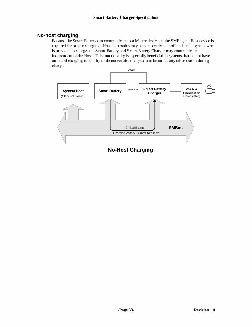
Smart Battery Charger Specification
-Page 33- Revision 1.0
No-host chargingBecause the Smart Battery can communicate as a Master device on the SMBus, no Host device isrequired for proper charging. Host electronics may be completely shut off and, as long as poweris provided to charge, the Smart Battery and Smart Battery Charger may communicateindependent of the Host. This functionality is especially beneficial in systems that do not haveon-board charging capability or do not require the system to be on for any other reason duringcharge.
System Host Smart BatteryChargerSmart Battery
Vbatt
Charging Voltage/Current Requests
SMBusCritical Events
AC-DCConverter
ACThermistor
No-Host Charging
(Unregulated)(Off or not present)
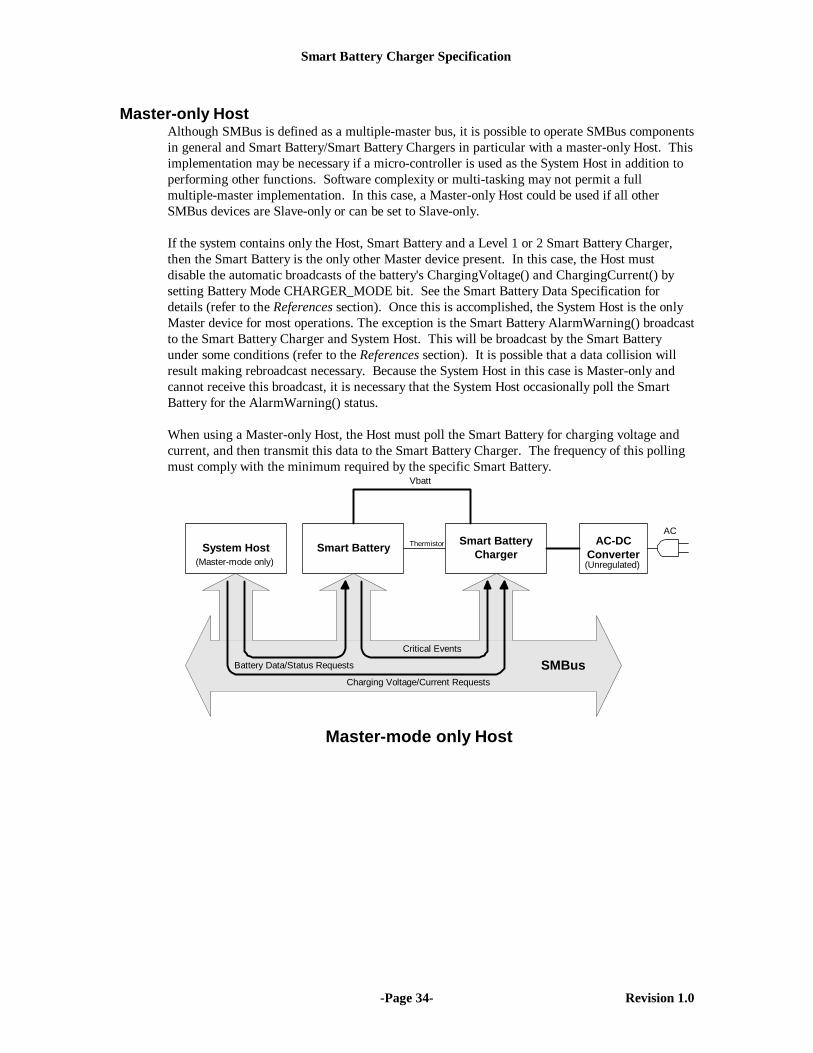
Smart Battery Charger Specification
-Page 34- Revision 1.0
Master-only HostAlthough SMBus is defined as a multiple-master bus, it is possible to operate SMBus componentsin general and Smart Battery/Smart Battery Chargers in particular with a master-only Host. Thisimplementation may be necessary if a micro-controller is used as the System Host in addition toperforming other functions. Software complexity or multi-tasking may not permit a fullmultiple-master implementation. In this case, a Master-only Host could be used if all otherSMBus devices are Slave-only or can be set to Slave-only.
If the system contains only the Host, Smart Battery and a Level 1 or 2 Smart Battery Charger,then the Smart Battery is the only other Master device present. In this case, the Host mustdisable the automatic broadcasts of the battery's ChargingVoltage() and ChargingCurrent() bysetting Battery Mode CHARGER_MODE bit. See the Smart Battery Data Specification fordetails (refer to the References section). Once this is accomplished, the System Host is the onlyMaster device for most operations. The exception is the Smart Battery AlarmWarning() broadcastto the Smart Battery Charger and System Host. This will be broadcast by the Smart Batteryunder some conditions (refer to the References section). It is possible that a data collision willresult making rebroadcast necessary. Because the System Host in this case is Master-only andcannot receive this broadcast, it is necessary that the System Host occasionally poll the SmartBattery for the AlarmWarning() status.
When using a Master-only Host, the Host must poll the Smart Battery for charging voltage andcurrent, and then transmit this data to the Smart Battery Charger. The frequency of this pollingmust comply with the minimum required by the specific Smart Battery.
System HostSmart Battery
ChargerSmart Battery
Vbatt
Charging Voltage/Current Requests
Battery Data/Status Requests SMBusCritical Events
AC-DCConverter
ACThermistor
Master-mode only Host
(Unregulated)(Master-mode only)
Smart Battery Charger Specification
-Page 35- Revision 1.0
Appendix E Accuracy RequirementsAmong the many benefits of Smart Battery Chargers and the Smart Battery model in general isthe low system cost that results from not duplicating costly measurement and controlcomponents. A Smart Battery already contains A/D conversion and other measurementelectronics of sufficient accuracy to provide state of charge, remaining capacity and otherinformation for that battery. It is not necessary to duplicate this measurement capability at thecharger, nor is required to exceed or even meet the level of accuracy internal to the SmartBattery, because the battery already contains a sophisticated measurement system and a methodof communicating with the Smart Battery Charger (SMBus).
The Smart Battery has everything necessary to ‘close the loop’ around the Smart Battery Chargerand therefore control the accuracy of the charging voltage and current. For this reason, theSmart Battery Charger is not expected to be as accurate or precise as the Smart Battery. Even theaccuracy of the thermistor inputs is regarded as that necessary only for safe charging, not soaccurate as to optimize charging. Under normal conditions the Smart Battery is in the bestposition to measure internal voltages, currents and temperatures to optimize charging.
For these reasons, the data provided by the Smart Battery to the Smart Battery Charger isexpected to be more accurate and of higher resolution than the Smart Battery Charger may beable to provide. If the resulting charge condition is unsuitable, the Smart Battery could send newvalues to the Smart Battery Charger as in the following example:1. The Smart Battery sets the ChargingCurrent() of the Smart Battery Charger to 1A2. The Smart Battery Charger responds by providing .95A, within its ±5% accuracy
requirement.3. The Smart Battery measures the charge current of .95A and calculates a new target of
1A/.95A = 1.052A and set the ChargingCurrent() of the Smart Battery Charger to this valueto correct the charge current
4. The Smart Battery Charger responds by increasing the output current proportionally, to 1A.5. The Smart Battery accepts this as the final charge current.
The Smart Battery could likewise set the ChargingVoltage() in the same fashion. Note that thedecision to “close the loop” is made by the Smart Battery’s manufacturer based upon the needs ofthe battery. There is no additional requirement placed in the Smart Battery Charger or SystemHost.
NOTE: Safety factors must be a prime consideration when Smart Battery manufacturersdevelop closed-loop charging algorithms as described here. Batteries pose a significantpotential risk of fire and explosion if mistreated AND this includes CHARGING.

Smart Battery Charger Specification
-Page 36- Revision 1.0
Appendix F Thermistor CharacterizationThe following graph describes the expected behavior of the thermistor described in this document. Thegraph is typical of the suggested thermistor's characteristics. It represents the electrical behavior of a103ETB type thermistor, which is nominally 10K ohms at 25°C ±5% or better.
Typical Thermistor Characteristics
0.1
1
10
100
1000
-50
-40
-30
-20
-10 0 10 20 30 40 50 60 70 80 90 100
110
Degrees Centigrad
K O
hms
Resistance
###