small scale brick making
DESCRIPTION
aTRANSCRIPT
A project of Volunteers in Asia
Small-Scale Brickmaklq
Published by:
International Labour Office (ILO) CH-1211 Geneva 22 SWITZERLAND
Copyright 1984
Available from:
Publications Branch, ILO, same address
Reproduced by permission.
Reproduction of this microfiche document in any form is subject to the same restrictions as those of the original document.

.
international Labour Office Geneva
TECHNOLOGY SERIES Technical memorandum No. 6
Prepared under the joint auspices of the lnternationtil Labow Office and the United Nations Industrial Development Organisation
International Labour Office Geneva

Copyright 0 International Labour Organization 3984
Publications of the !nternational Lsbour Office enjoy copyright under Protocol 2 of the Universal Copyright Convention. Nevertheless, short excerpts from them may be reproduced without authoriaation, on condition that the source is indicated. For rights of reproduction or translation, application should be made to the Publications Branch (Rights and Permissions), International Labour Office, CW!211 Geneva 22, Switzerland. The International Labour Office welcomes such applications.
lS8N 92-2-103567-o
iSSN 0252-2004
Fkst publkhed 1984
The designations employed in IL0 publications, which are in conformity with United Nations practice, and the presentation of material therein do not imply the expression of any opinion whatsoeveron the part of the International Labour Office concerning the legal status of any country or territory or of its authoritieqor concerning the delimitation of its frontiers. The responsibility for opinions expressed in signed articles, studies and other contributions rests solely with their authors, e.nd publication does not constitute an endorsement by the International Labour Office of the opinions expressed in them. Reference to names of firms ar?d commercial products and processes does not imply their endorsement by the Inter- national Labour OfFice, and any failure to mention a particular firm, commercial product or process in connection with the technologies described in this volume is not a sign of disapproval.
IL0 publications can be obtained through major booksellers or IL0 local officea in many countries, or direct from 110 Publications, International Labour Office, CH-TP!? Geneva 22, Switzerland. A catalogue or list of new publications will be sent free of charge from the above address.
Printed in Switzerland

TABLE OF CONTENTS
ACKNOWLEDGEMENTS . . . . . . . . . . . . . . . . . ..~................................... vii
PREFACE .
. . . . . . . . . . . . . . . . . . . . . . . . . . . . . . . . . . . . . . . . . . . . . . . . . . . . . . . . . . . . . . . . 1x
CHAPTER I
I.
II.
III.
IV.
v,
CHAPTER II RAW MATERIALS 13
I.
II.
III.
CHAPTER III QUARRYING TECHNIQUES 35
I. Organisation and management of the quarry 35
II. Methods of winning the clay 38
III. Transportation to the works 41
CHAPTER IV CLAY PREPARATION 43
I. Main clay preparation phases 45
II. Sorting 45
III. Crushing 47
IV. Sieving 51
V. Proportioning 53
VI. Mixing, wetting and tempering 53
VII. Testing 58
INTRODUCTION . . . . . . . . . . . . . . . . . . . . . . . . . . . . ..*...............
Purpose and objectives of the memorandum
Target audience
Comparison between bricks and other building materials
Scales of production covered by this memorandum
Content of the memorandum
Origin and distribution of raw materials
Types of clay
Clay trusting and significance of results
1
1
3
4
9
11
13
16
24

CHAPTER V
I. Description of bricks to be produced 61
II. Methods of shaping 64
III. Transportation of bricks to drying areas 79
IV. Skill requirements and training 79
v. Productivity of labour 82
CHAPTER VI DRYING 85
I. Objectives of drying 85
II. Artificial drying 86
III. Natural drying 88
IV. Shrinkage 95
'iv'
SHAPING
CHAPTER VII FIRING 99
I. Objectives of firing 99
II. Techniques of firing 100
III. Kiln design 101
IV. Auxiliary equipement 134
v. Fuel 136
VI. Productivity 139
VII. Brick testing 141
CHAPTER VIII MORTARS AND RENDERINGS 149
I.
II.
III.
CHAPTER IX ORGANISATION OF PRODUCTION 159
I. Preliminary investigations 159
II. Infrastructure 160
III. Layout 163
IV. Skill requirements 167
Purpose and principles
Mortar types
Mixing and use
61
149
150
154
-V-
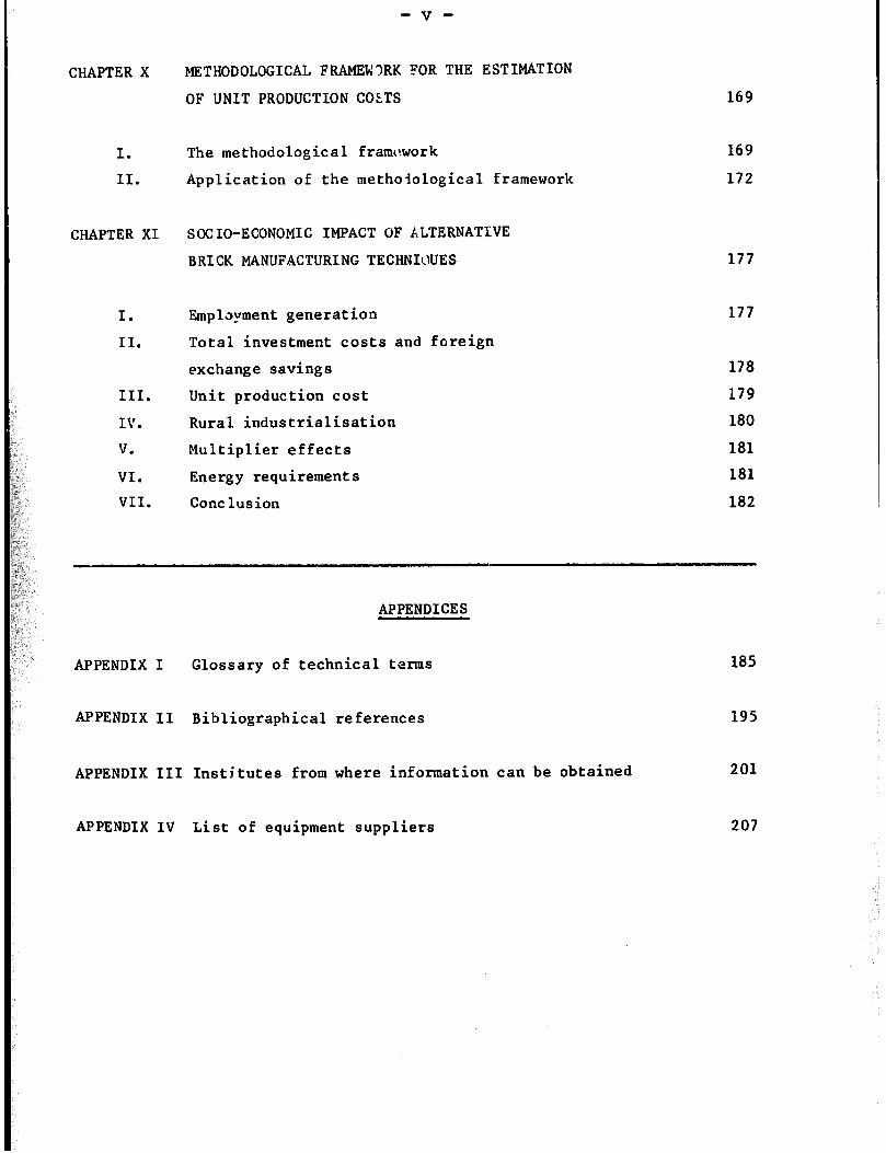
CHAPTER X
I.
II.
CHAPTER XI
I.
II.
III.
IV.
V.
VI.
VII.
METHODOLOGICAL FRAMEWRK FOR THE ESTIMATION
OF UNIT PRODUCTION COLTS
The methodological framework 169
Application of the methoiological framework 172
SOCIO-ECONOMIC IMPACT OF ALTERNATIVE
BRICK MANUFACTURING TECHNIWES
Employment generation
Total investment costs and foreign
exchange savings
Unit production cost
Rural industrialisation
Multiplier effects
Energy requirements
Cone lusion
169
177
177
178
179
180
181
181
182
APPENDICES
APPENDIX I Glossary of technical terms
APPENDIX II Bibliographical references
APPENDIX III Institutes from where information can be obtained
APPENDIX IV List of equipment suppliers
185
195
201
207
ACKNOWLEDGEMENTS
The publication of this memorandum has been made possible by a grant from
the Swedish International Development Authority (SIDA). The Intexational
'babour Office and the United Nations Industrial Development Organisation
acknowledge this generous support.

PREFACE
This technical memorandum on small-scale brickmaking is the sixth of a
series of memoranda being currently prepared by the IL0 and UNIDO. It is the
first of three technical memoranda on building materials for lowcost
housing.'
The main objective of technical memoranda is to provide small-scale
producers in developing countries with detailed technical information on
small-scale technologies, which have been successfully applied in a number of
countries, but are not well known outside the latter. A secondary objective
is to assist public planners identify and promote technologies consonant with
national socio-economic objectives, such as employment generation, foreign
exchange savings, rural industrialisation, or the fulfilment of the basic
needs of low-income groups.
The information contained in the memoranda is detailed enough to ensure
that small-scale producers should be able, in a large number of cases, to
identify and apply the technologies described in the memoranda without the
need for further information. Thus, detailed drawings of equipment, which may
be manufactured locally, are provided, while a list of equipment suppliers,
from both developed and developing countries, may be used for the acquisition
of equipment which must be imported. In the few instances where the available
information is not sufzicient, the raader may obtain additional technical
details fram publications listed in the bibliography or from technology
institutions identified in a separate appendix of the memoranda.
Technical memoranda are not intended as training manuals. It is assumed
that the potential users of the technologies described in the memoranda are
trained practitioners and that the memoranda are only supposed to provide them
with information on alternative technological choices. Memoranda may,
however, be used as complementary training material by training institutions.
1 The other two technical memoranda, currently under preparation, cover
respectively the production of stabilised earth blocks and that of windows and
doors., /

-X-
This technical memorandus on small-scale brick manufacturing is of
particular importance to developing countries as low-cost housing constitutes
one of the most important basic needs of low-income groups, and bricks are
particularly suitable materials for the construction of this type of housing.
Furthermore, the adoption of small-scale brickmaking techniques should
generate substantial employment, especially in rural areas. It is hoped that
the information contained in this memorandum will slow down the adoption of
large-scale, capital-intensive, turnkey brickmaking plants which have often
proved to be unsuitable for conditions prevailing in the majority of
developing countries.
7
T s memorandum contains 11 chapters, nine of these dealing with the
various subprocesses in brick manufacturing. Chapter X provides a
methodological framework for the estimation of the unit production cost of
bricks, using the technical data from the previous chapters. It is of
particular interest to potential brickmakers who wish to identify the
least-cost or most profitable production technique. Chapter XI is mostly
intended for public planners and project evaluators from industrial
development agencies who wish to obtain information on the various
socio-economic effects of alternative brickmaking techniques with a view to
identifying and promoting those which are particularly suitable to local
socio-economic conditions.
This memorandum also contains four appendices which could be of interest
to the reader. Appendix I provides a glossary of technical terms, and should
therefore be of assistance to non-specialists. Appendices II and III provide
sources of additional information, either from available publications
(Appendix II> or from specialised technology institutions (Appendix III).
Finally, Appendix IV provides a list of equipment suppliers from both
developing and developed countries. It may be noted that this list is far
from being exhaustive, and that it does not imply a special endorsement of
these suppliers by the ILO. The listed names are only provided for
illustrative purposes, and brickmakers should try to obtain information from
as many suppliers as feasible.
A questionnaire is attached at the end of the memorandum for those
readers who may wish to send to the IL0 or UNIDO their comments and
observations on the content and usefulness of this publication. These will be

- xi-
taken into consideration in the future preparation of additional technical
memoranda.
This memorandum was prepared by Mr. R.G. Smith (consultant) in
collaboration with Mr. M. Allal, staff member in charge of the preparation o;r'
the Technical Memoranda series within the Technology and Employment Branch of
the International Labour Office.
A. S. Bhalla,
Chief,
Technology and Employment Branch.
Q
CHAPTER I
INTRODUCTION
I. PURPOSE AND OBJECTIVES 3F THE MEMORANDUM
Housing constitutes one of the most important basic needs of low-income
groups in develcping countries. However , it is the most difficult to satisfy
as land and building costs are often outside the means of the unemplayed and
underemployed in both rural and urban areas. Thus, many governments have
launched various schemes with a view to facilitating housing ownership by
low-income groups, including self-help housing schemes, granting of housing
subsidies, provision of credit at low interest rates, etc. Given the limited
means at the disposal of governments and potential home owners, it is
important to seek ways to lower the cost of lowincome housing while
minimising repair and maintenance costs. In particular, governments should
promote the production and use of cheap yet durable but: iing materials as the
latter constitute a very large proportion of total iow-income housing costs in
developing countries(l). Furthermore, it would be useful if the production of
these building materials could contribute to the fulfilmeiat oi important
development objectives of these countries, such as the generat ion of
productive employment, rural industrialisation, and a decreased dependence on
essential imports.
A number of traditional building materials exist which have proved
themselves to be the most suitable materials for use in a wide variety of
situations, and have a great potential for increased use in the future. These
traditional materials, which make use of locally available raw materials, can
be manufactured close to the construction site with little equipment (which
may be produced locally), and are often more appropriate to the environment
than modern materials. One such building material is clay bricks. The
purpose of this technical memorandum is to provide detailed technical and
economic information on small-scale brick manufacturing with a view to
assisting rural and urban entrepreneurs to start up new plants or improving
their production techniques. It is also hoped that the information contained
in this memorandum will help slow down the establishment of large-scale,
-2-
capital-intensive plants which are not always suitable to socio-economic
conditions of developing countries.
I.1 Need for improved brick production techniques
Various production methods are used for brickmaking in developing
countries. Traditional hand digging, moulding and handling are used by a
large number of small production units. Some larger units tend to use
equipment for digging or mixing, while a number of developing countries have
chosen to import large-scale capital-intensive‘ plants.
The choice of brickmaking technology is mostly a function of market demand
(e.g. scale and location of demand, required quality standard), availability
of investment funds, and unit production costs associated with alternative
production techniques. In some cases, governments may also impose various
policy measure:; with a view to favouring the adoption of techniques consonant
with the national development objectives. Whatever the adopted technique,
quality may be improved and costs reduced if appropriate measures are taken
during the production process.
Experience shows that a large fraction of bricks are often wasted during
the various production stages. For example, moulded bricks get eroded by the
rain before firing or distorted by bad handling methods. Sometimes,
incorrectly adjusted machines yield inconsistent or inferior output which may
not be marketed. With attention to the basic principles of brickmaking and
more care, a greater number of bricks could be produced for the same
expenditure of labour, raw materials and fuel.
In some instances, more careful preparation of raw materials would
minimise problems at subsequent manufacturing stages. For example, if stones
or hard dry lumps of clay are included in the moist clay used for moulding,
they will exhibit different drying shrinkages from the moist clay and give
rise to cracks in the dried or fired bricks. The remedy in such a case would
have been to select a more uniform raw material, or to remove the offending
particles, or to break the material down to a fine size (e.g. by manual means
or with a crushing machine).
Use of a good product, of regular shape and size and of consistent
properties, will enable the accurate building of walls while minimising the
use of mortar between bricks. Renderings, often applied in developing
countries, will also require less mix for a given wall area if the brickwork
face is accurate. Alternatively, if the brick quality is sufficiently good,
it may be unnecessary to apply renderings at all. A good product will thus
favourably impress the customer and save materials, time and money. It should

-3-
therefore improve future demand for the product. Good bricks should be
durable and brickwork should be long lasting.
I.2 Availability of information on brickmaking
The techniques of brickmakinp are often handed down from father to son in
small works, or are taught in various technical schools, training cent res,
etc. Articles and books have been published(2) but are often too brief or
mostly concerned with large-scale production, scientific investigations or
laboratory tests. They also often relate to conditions and needs of the more
developed countries. With few exceptions(31, there is a lack of information
on practical details of small-scale production in rural or peri-urban areas.
Information on sophisticated high capital cost brickmaking plants can be
obtained firm published books and scientific and trade journals, or from
equipment manufacturers and consultants. On the other hand, it is more
difficult to obtain information on small-scale, labour-intensive production.
Many appropriate technology institutes, building research centres and
university departments do generate information on appropriate production
techniques (see list in Appendix III). However, this information is either
not published or is not disseminated to other developing countries. This
memorandum seeks, therefore, to provide information on small-scale brickmaking
with a view to partially filling the current information gap. It does not
provide technical details on all possible circumstances, but will, it may be
hoped, induce small-scale producers to try production techniques which have
already been successfully adopted in a number of developing countries.
II. TARGET AUDIENCE
This memorandum is intended for several groups of individuals in
developing countries, including the following:
- small-scale brickmaking producers in rural and urban areas, and those
considering starting brick production. These could be either individual
entrepreneurs or groups of artisans associated in a manufacturing
co-operative. These producers will be mostly interested in the information
contained in Chapters II to VII, and Chapters IX and X.
- housing authorities, public planners and project evaluators in various
industrial development agencies may be interested in the information contained
in Chapters 11 and XI. This latter chapter, which focuses on the
socio-economic implications of alternative brickmaking techniques, will be of
particular interest to public planners concerned with employment generation,
foreign exchange saving, etc.
- financial institutions, businessmen, government officials and banks should
-4-
be mostly interested in Chapter X which provides the necessary information for
costing alternative production techniques.
- handicraft promotion institutions, village crafts organisations and
equipment manufacturers should find the technical chapters II to VII useful.
- voluntary organisations, foreign experts, extension workers and staff of
technical colleges will :.rish to compare bricks with other building materials,
as detailed in Chapter I (section III). They may also benefit from the
technical information contained in Chapters II to VII.
It must be stressed that this is not a technical memorandum on the use of
bricks in building, although some of the information contained in Chapter VIII
may be of interest to builders.
III. COMPARISON BETWEEN BRICKS AND OTHER BUILDING MATERIALS
This section compares the properties of fired clay bricks with those of
other alternative walling materials. Table I.1 gives specific values for some
of the properties discussed below. This comparison should be useful to
housing authorities in deciding which building materials should be most
appropriate for various types of housing or housing projects.
III. 1. Strength
Compressive strength of fired-c lay bricks varies enormously, depending
upon clay type and processing. Strength requirements for single-storey
housing are easily met.
Calcium silicate bricks, made from sand with high silica content and good
quality, low magnesia, lime, may have strengths approaching those of good
fired clay bricks. However, high capital cost machinery is used for the
mixing, pressing and autoclaving. Furthermore, calcium silicate bricks must
be produced in large-scale plants.
Concrete bricks and blocks have sufficient strength, but require cement
which is expensive, and must often be imported.
Lightweight concrete blocks, made with either natural or artificial
lightweight aggregate, have adequate strength but require cement.
Aerated concrete has low strength which may be sufficient for one-storey
buildings. Particularly careful production control is necessary, using
autoclaving to reduce subsequent moisture shrinkage of blocks made from this
material.
Many types of soil have sufficient compressive strength when dry.
However, this strength is considerably reduced once they become saturated with
water.

--5 I
hl
d m .
r- d 0 u
ln
d
G-4 0 u 0
4-l
2 u-l
d ;
0 Ub
a-8 OC.
s
I--
d
0 U
0 N
0 u
N In l-3
d d d
OQI uu rd “0: “;
N
d a
0 u
N
0 U
l-l
d d d
6
d c\I
. c\I
0 U 0
U
z r-
h .
4 0 In
0 u
0 U
I-. 0 .
d d . d
00) UU
\o .
t-i
0 u
I-4
A
0 d
0
d 4
N’ 0
c-l
zl
0 U
b .
0
u 0 JJ
0 4
4
-6-
Waterproofers such as bitumen, or stabilisers such as lime or cement, may
be used with certain soils to improve wet strength. On the other hand, the
strength of the other previously mentioned materials is only reduced slightly
when they are wetted.
Gypsum, which occurs as a soft rock, or in some places as a fine sand, can
be converted to plaster by gentle heating and then mixed with fine and coarse
aggregate and cast into building blacks(5). Strength will be adequate for
single-storey constructions, though wetting will reduce compressive strength
to 50 per cent of the dry value.
Thus bricks are.seen to be at the top of the list for strength, especially
when wet.
Many other walling systems exist, notably panels made either from woven
plant leaves or stems, or manufactured from cement, plastics, wood or metal.
However, the strength of walls made from these panels will depend largely upon
the frame which is built to hold them.
111.2. Moisture movement
Most porous building materials expand when wetted and contract again as
they dry. Excessive movement can cause spalling, cracking or other failures
in buildings. This reversible expansion is very small in fired clay bricks.
However, a slow irreversible expansion commences as soon as bricks leave the
kiln. This irreversible expansion may vary from virtually zero to 0.1 per
cent linear movement. Under normal circumstances much of this expansion will
have taken place before bricks are built into walls. Thus, the remaining
expansion is likely to be insignificant in the context of small buildings(6).
Properly made calcium silicate bricks and concrete bricks are unlikely to
have more than a fairly small amount of moisture movement. However,
lightweight and aerated concrete units exhibit a greater movement. This
sometimes leads to shrinkage cracking in buildings as they dry out initially.
Soil, especially plastic clay, may have a very large moisture movement of
several percentage points. This is a major cause of failure in earth
building. The problem is reduced if stabilisers are incorporated into the
soil. *
Timber, bamboo and other plant materials exhibit variable, but sometimes
large, moisture movements. The latter take place especially across the grain
rather than in line with it.
Moisture movement becomes especially important when two materials with
different movement characteristics are in close juxtaposition in a building.
Differential movements give rise to stress which may be sufficient to break
the bond between the materials, or lead to other damage. For example, cement
renderings often become detached from mud walling, and gaps appear sometimes
between timber frames and infill materials.

-7-
Bricks thus compare favourably with alternative constructio,l materials.
Moreover, brickwork can be built without timber frames, thus excluding the
possibility for differential movements.
111.3. Density and thermal properties
Fired clay bricks are amongst the most dense of building materials. This
high density may constitute a disadvantage for transportation over long
distances or in multi-storey framed buildings where the loads on frames would
be high. On the one hand, weight is of little consequence whenever bricks are
produced locally for close-by markets and single-storey buildings. On the
other hand, the high density of bricks has the advantage over lightweight
building materials of greater thermal capacity. This characteristic is sought
in the tropics where extremes of temperature will be moderated inside
buildings made of bricks.
Aerated and lightweight aggregate concretes have good thermal insulating
properties but lack thermal capacity, while thick mud walls have fairly good
insulation and good thermal capacity. Lightweight cladding materials, such as
woven leaves and matting, metal sheeting and asbestos cement sheeting, have
neither high insulation nor high thermal capacity.
Thus, bricks are particularly advantageous for low-cost housing as they
considerably improve environmental conditions within the building.
III.4. Durability, appearance and maintenance
Evidence for the excellent durability of brickwork may be seen in many
countries of the world. In the Middle East, brickwork 4,000 years old still
remains. Bricks made 2,000 years ago in Roman times are still in use today.
Indeed, properly made bricks are amongst the most durable of materials, having
typical properties of ceramics such as good strength, resistance to abrasion,
sunlight, heat and water, excellent resistance to chemicals and attacks by
insects and bacteria, etc. If bricks are not well made (e.g. if the time or
temperature in the kiln is insufficient), these desirable ceramic properties
will not be developed, and performance will be nearer to that of mud bricks.
Furthermore, to achieve the best performance from brickwork, attention must be
paid to the correct formulation and use of mortar. Fired clay brickwork
should sustain the adverse impact of the environment without the need of any
surface protection (e.g. rendering). NC maintenance should be required
subsequent to building.
In some communities it is traditional to render the brick wall surface,
although this is not necessary from either the appearance or performance point
of view. Furthermore, lime washing on rendering is often used to achieve a
-8-
white finish. A white finish is beneficial in reducing solar gain. It may be
applied directly on the bricks without rendering, thus saving materials.
Other brick and block materials may also have good durability, if well
made. However, the lightweight aggregate, aerated concrete and mud bricks
normally require rendering to improve resistance to water.
The ultra-violet component of sunlight causes deterioration of many
organic materials. These include timber and other plant-derived materials,
plastics, paints, varnishes and bitumen. Inorganic materials, such as bricks,
are immune to sunlight deterioration.
Termites occur in many developing countries and can attack and damage soft
materials such as various species of timber. Other insects also attack
timber. Hard materials such as bricks are entirely resistant.
Under damp conditions, timber and many other organic materials may rot
through attacks by fungi, moulds and bacteria. Although some plant growth and
mould may be seen on porous inorganic building materials, especially in
hot-damp climates, damage is unlikely.
Fire can quickly destroy many building materials such as timber, woven
matting and plastics. Cement products do not burn, but high temperatures in
fires could break down some of the calcium and alumino silicates of which they
are composed, causing loss of strength. In practice concrete may successfully
sustain somewhat elevated temperatures without serious effect, though if
concrete contains siliceous aggregates, such as flint, it is likely to
spall( 7). Reinforcing steel and steel frames lose strength and distort in
fire, but are normally encased, and are thus protected to a large extent.
Although clay brickwork could spall, crack and bulge in a severe fire, bricks
are less likely to suffer damage than concrete and calcium silicate bricks as
they have already been exposed to fire. Sudden cooling of hot areas by
quenching with water in the course of fire-fighting may cause spalling. This
does not generally affect the strength and stability of the brick wall
seriously.
111.5. Earthquake areas
In general, bricks and blocks, whether of fired clay, calcium silicate,
concrete, or stabilised soil, require steel reinforcement in seismic zones .
Mud building, lightweight concrete and aerated concrete materials will also be
at risk in these areas if not similarly reinforced.
111.6. Production cost and foreign exchange
The production costs of various building materials depend upon raw
materials prices, methods used, markets, etc. which vary from time to time and

place to place, making comparisons difficult. However, bricks are often
amongst the cheapest of walling materials. It should be borne in mind that
if, as stated at a United Nations Conference, a house is to retain its
usefulness, it must be maintained, repaired, adapted and renovated. Thus,
choices concerning standards, materials and technology should consider
resource requirements over the whole expected life of the asset and not merely
the monetary cost of its initial production(8). Durable materials such as
bricks have a cost advantage in this respect.
The product ion of bricks from indigenous clays, especially if
labour-intensive methods are used to avoid importation of capital-intensive
equipment, will conserve foreign exchange. This is in contrast with some of
the alternative materials.
IV. SCALES OF PRODUCTION COVERED BY THIS MEMORANDUM
Bricks manufacturing may be undertaken at various scales of production,
depending upon local circumstances. Table I.2 summarises the production
techniques used at small, medium and large scales of production.
Table I.2
Scales of production in brick manufacturing
Scale of
product ion
Number of bricks Appropriate for
per day Example of process used market area
C average)
Small 1 000 Hand made, clamp-burnt Rural village
Medium 10 000 Mechanised press, Bull’s ,
trench ki In Near towns
Large 100 000 Fully automated
Extruded wire cut,
tunnel kiln
Industrialised
areas of high
demand and well-
developed inf ra-
structure
This memorandum is concerned primarily with small-scale production, though
some consideration is given to medium-scale. Large-scale will be mentioned
briefly for comparative purposes.
- 10 -
IV. 1 Small-scale concept
A small brickworks producing 1,000 bricks per day may supply enough bricks
each week for the building of an average size house. This may be adequate in
a small village community. However, if demand were to increase suddenly,
production could be increased to several thousand bricks per day merely by
making additional wooden moulds and hiring more workers. In this case, the
management staff does not need to be expanded. This larger production unit
might also be established in small towns. Conversely, at times of recession
or when weather prevents construction work, the demand will fall and
production can be reduced temporarily. Thus, such small-scale industry is
very adaptable to a changing market.
Small-scale production should be undertaken near the clay source, and
within a short distance of the area where bricks will be sold and used. This
will reduce transport cost while saving fuel. Small-scale production will not
unduly spoi 1 the landscape nor cause excessive pollution. An electricity
supply may not be necessary and fossil fuels need not be used. Kilns may
utilise waste materials for fuel, such as saw dust, rice husks, animal dung
and scrub wood. The small works will provide employment within the local
community. Capital investment is low for small-scale production and is thus
appropriate for poor communities. Furthermore, equipment for small-scale
brickmaking can be made and repaired within the local community.
IV.2. Large-scale concept
In contrast to the points mentioned above, the introduction of large
brickworks necessitates capital investment of millions of dollars, mostly in
foreign exchange for th.e import of the sophisticated production machines and
control systems. Commissioning over a period of months and subsequent
purchase of spares will further increase costs. Large areas will have to be
cleared not only for the works, but also for the clay pit. The process itself
and the transport of raw materials and products can prove a nuisance.
Production of many millions of bricks per year necessitates the finding of
sufficient markets, and involves the use of fuel for getting bricks to the
building sites. Feasibility studies for large-scale plants commonly assume
several shifts being worked per day for nearly all the days of the year. Such
plants are not adaptable to variations in market demand. There is no allowance
for workers’ absenteeism (e.g. during the agricultural season). neither do

- 11 -
they ususally take into account the difficulty of obtaining spare parts from
overseas in the event of a breakdown. If the latter does occur, the whole
production ceases. These large plants require electric power and high grades
of fuel for the kilns.
In those situations where a large plant may be considered, it would be
normal to conduct a full feasibility study, examining raw material quality and
reserves for the expected life of the works (e.g. 50 years), and a thorough
market survey. A specialist consultant would be required for such a
feasibility study.
V. CONTENT OF THE MEMORANDUM
The following eight chapters of this memorandum deal with the technical
aspects of brick manufacturing. Chapter II describes various raw materials-
entering in the production of bricks while Chapters III to IX describe the
various production processes in the following order:
Chapter III : Quarrying (methods and equipment)
Chapter IV : Preprocessing (grinding, sieving, wetting, etc.)
Chapter V : Forming (equipment, skill requirements, etc.)
Chapter VI : Drying (natural and artificial, drying shrinkage, etc.)
Chapter VII : Firing (kiln types, fuels, etc.)
Chapter VIII: Mortars and renderings (purpose, types, etc.)
Chapter IX : Organisation of production (plant layout,
water and fuel supplies, labour, etc.)
Technical details on each subprocess are provided, including advice for
improving product quality, saving fuel, increasing labour productivity,
minimising losses, etc.
Chapter X out1 ines a methodological framework for estimating unit
production costs associated with alternative production techniques. An
illustrative example is provided with a view to showing how this framework may
be applied to a specific bricks production unit. Finally, Chapter XI analyses
the various socio-economic effects of alternative production techniques,
including employment generat ion, foreign exchange savings, fuel utilisation,
etc. The memorandum concludes with the following appendices: Glossary of
technical terms, bibliography, list of institutions concerned with
brickmaking, and list of equipment suppliers.
Note:
’ The references are to entries in the bibliography (Appendix II).

CHAPTER II
RAW MATERIALS
I. ORIGIN AND DISTRIBUTION OF RAW MATERIALS
Brickmaking requires sufficient supplies of suitable soil., sand, water and
fuel. The purpose of this chapter is to describe the various types of clay
which mav be used in brickmaking.
The essential ingredient in the soil used for brickmaking is clay. The
size of each clay particle is extremely small, generally less than 0.002 mm
across. Various forces act between these fine particles in a moistened clay,
allowing the latter to be formed into the desired shape, which must be
retained on drying. Clayey materials can be readily identified by simple
manipulation of moist samples with a view to checking the plasticity of the
latter.
A wide variety of raw materials may be used for brickmaking, ranging from
soft sticky muds to hard shales. However, all these materials must contain a
moderate proportion of clay-size particles. Too high a proportion of such
particles will result in excessive shrinkage of moulded bricks as they dry,
with consequent risk of cracking. On the ether hand, a soil with too low a
proportion of clay particles will not be cohesive enough and will fall apart.
The mineralogical nature of the clay must be suiiable so that it is changed by
heating in a kiln to a strong, water resistant vitrified form which can bind
larger particles in the soil together.
Brickmaking clays may be found in most countries of the world.
Geologically recent deposits are associated with existing valleys and rivers,
and are often near the surface. Older deposits may be overlaid by other
unsuitable material of varying depth, and may have been raised and inclined
from their original positions. Thus, good deposits of clay may be found in
gently rolling hills, but not mountains.
Information on clay deposits is available in many countries from National
Geological Survey Departments, or may be obtained from Geological Institutes.
Location of existing brickworks, pottery works or other ceramic production is
evidence of workable deposits.
Prospecting for new clay deposits may be undertaken by first examining
river banks, and the sides of any recent road or railway cuttings which give
an instant section of the soil profile. Subsequently it is necessary to
explore in more detail any newly-discovered deposits by taking samples from
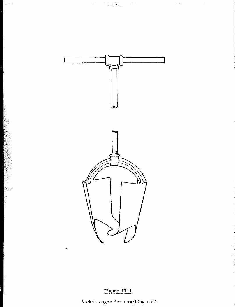
many points on a regular grid covering the ground area. The neatest and
simplest means of obtaining a suitable sample is by using an earth auger. The
latter can be powered by one or two people. As it is rotated, the auger
drills its way down into the earth, providing samples of the cut out soil.
Alternatively, a spade may be used to dig a narrow hole (figure 11.2).
However, it cannot go as deep as an auger. A pit may be dug instead in such a
manner that a person with the spade can work on the floor of the pit. This
will require the removal of a great volume of earth, and may not therefore
constitute an efficient way of taking samples. For safety’s sake the pit
should not be more than 2 metres deep.
It is wise to keep an accurate record of such investigations. A plan of
the Zi2S should be drawn, and location of investigatory holes marked in and
numbered. Samples taken out of the hole should be small enough to allow the
identification of a change from one soil type to another. Usually, there is a
top-soil in which plants grow, and which contains the decomposed products of
plants. The top-soil depth should be measured and noted, as well as that of
subsequent soil layers. As soon as clay is found, it will be recognised by
the stickiness with which it adheres to the auger or spade. If a large stone
is encountered when augering , it will have to be knocked out of the way, or
broken, or a different type of auger used to cut a way past.
The survey will indicate the area covered by clay, its thickness and the
depth at which it may be found, and the thickness of the top soil which must
be removed during quarrying. If there is much top soil, it will not be worth
the cost of removing it unless there is a good depth of clay beneath.
Simple testing of clay for suitability for brickmaking may be carried out
on site. For more extensive testing, each soil type should be in a separate
heap on boards or a large sheet, then reduced by quartering. Quartering is
done by dividing the heap into four quarters of equal size and shape,
discarding two diagonally-opposed quarters, and recombining the other two.
This procedure is repeated until a small pile of a few kilograms remains. The
latter should be placed in a strong plastic bag, labelled with the hole
numbers and the depths from which the sample was extracted.
- 15 -
Figure II.1
Bucket auger for sampling soil
- 16 -
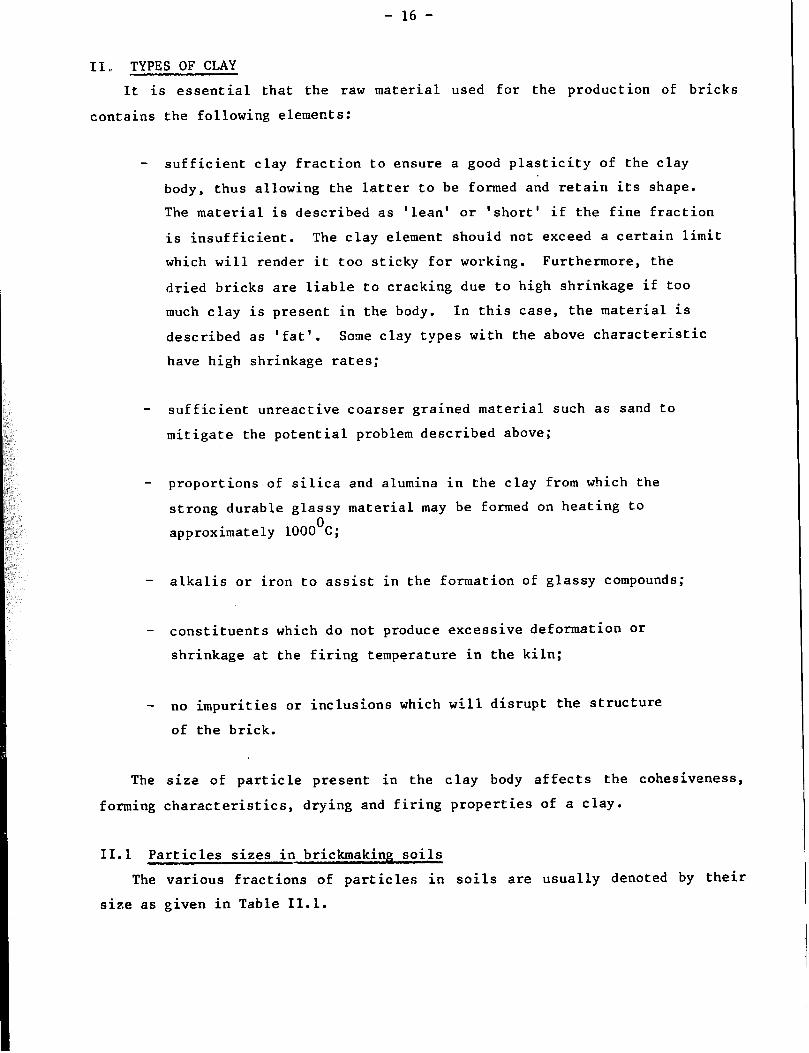
II, TYPES OF CLAY
It is essential that the raw material used for the production of bricks
contains the following elements:
- sufficient clay fraction to ensure a good plasticity of the clay
body, thus allowing the latter to be formed and retain its shape.
The material is described as ‘lean’ or ‘short’ if the fine fraction
is insufficient. The clay element should not exceed a certain limit
which will render it too sticky for working. Furthermore, the
dried bricks are liable to cracking due to high shrinkage if too
much clay is present in the body. In this case, the material is
described as ‘fat’. Some clay types with the above characteristic
have high shrinkage rates;
- sufficient unreactive coarser grained material such as sand to
mitigate the potential problem described above;
- proportions of silica and alumina in the clay from which the
strong durable glassy material may be formed on heating to
approximately 1000°C;
- alkalis or iron to assist in the formation of glassy compounds;
- constituents which do not produce excessive deformation or
shrinkage at the firing temperature in the kiln;
- no impurities or inclusions which will disrupt the structure
of the brick.
The size of particle present in the clay body affects the cohesiveness,
forming characteristics, drying and firing properties of a clay.
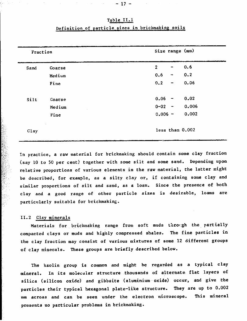
II.1 Particles sizes in brickmaking soils
The various fractions of particles in soils are usually denoted by their
size as given in Table 11.1.
- 17 -
Table II.1
Definition of particle sizes in brickmaking soils
Fraction Size range (mm)
Sand Coarse 2 - 0.6
Medium 0.6 - 0.2
Fine 0.2 - 0.06
Silt Coarse
Medium
Fine
0.06 - 0.02
O-02 - 0.006
0.006 - 0.002
Clay less than 0.002
In practice, a raw material for brickmaking should contain some clay fraction
(say 10 to 50 per cent) together with some silt and some sand. Depending upon
relative proportions of various elements in the raw material, the latter might
be described, for example, as a silty clay or, if containing some clay and
similar proportions of silt and sand, as a loam. Since the presence of both
clay and a good range of other particle sizes is desirable, loams are
particularly suitable for brickmaking.
II.2 Clay minerals
Materials for -brickmaking range from soft muds thro!:gh the. partially
compacted clays or muds and highly compressed shales. The fine particles in
the clay fraction may consist of various mixtures of some 12 different groups
of clay minerals. These groups are briefly described below.
The kaolin group is common and might be regarded as a typical clay
mineral. In its moiocuiar structure thousands of alternate flat layers of
silica (silicon oxide) and gibbsite (aluminium oxide) occur, and give the
particles their typical hexagonal plate-like structure. They are up to 0.002
mm across and can be seen under the electron microscope. This mineral
presents no particular problems in brickmaking.

- 18 -
The montmorillonite group,which often occurs in the drier tropics, has two
silica layers for every one gibbsite. This structure allows water molecules
to enter in between the layers, forcing them apart. The resulting expansion
of the clay may continue for several weeks under damp conditions(l7) The
layers close up again when the water is dried out. This has important
consequences in brickmaking since montmorillonite-bearing clays have large
drying shrinkages. The thin plates are generally smaller than kaolinite. The
high specific surface area gives great plasticity, stickiness and strength to
the montmorillonites( 17).
The hydrous micas and illites, which have somewhat similar structures to
the montmorillonites, are also frequently found in brickmaking materials.
Chlorites, which are related to hydrous micas, are also found in various clay
materials. The latter have magnesium and potassium within their structures.
Extremely small particles from a millionth to a thousandth of a millimetre
across, termed colloids, are also present in clays. They carry electrical
charges, so their movement in water and their properties are affected by the
presence of salts. ThrlS, the physical properties of wet clays can be altered
by additions of some chemicals which may, for example, increase their
plasticity or reduce stickiness. An acidic addition flocculates the
colloidal particles so they settle in water more readily whilst an alkaline
addition deflocculates these particles and keeps them in suspension.
Mineralogical examination can help identify the substances present with a
view to determining the likely suitability of a material for brickmaking.
II. 3 Chemical analysis
Chemical analysis can help in the identification of the clay minerals
present in the raw material. The relative proportions of silica and alumina
are relevant , since the higher the proportion of alumina, the higher the
temperature necessary to form the glassy ceramic bonding material which
charac teri ses ceramic products. Chemical analysis can also indicate the
presence of water-soluble compounds such as the sulphates of potassium, sodium
and magnesium. The drying out of the latter on the moulded bricks (before
firing) produce unsightly scumming. If still present in the fired product,
they may lead to efflorescence and, exceptionally, can spoil brick faces and
lead to attack and expansion of cement-based mortars. Calcium sulphate can
also produce this undesirable effect. With knowledge of these deleterious

I - 19 -
salts within the clay it might be possible to avoid problems with the bricks
when finally built into walls, by choosing another clay deposit or allowing
rain to wash salts out of the clay after it has been dug, or by firing the
bricks to a higher temperature. Another solution to these problems is to add
barium carbonate. This is, however, an expensive remedy which may not be
feasible in many situations.
If potassium and sodium are found in the chemical analysis, but the
compounds are not water soluble, they may indicate the presence of fluxes such
as the felspars or micas. These are beneficial in reducing the temperature
needed for formation of glassy material. Magnesium, calcium and iron
(ferrous) compounds can also behave as fluxes.
Chemical analysis may be carried out on different size fractions of the
soil. This is an important consideration since fluxes should be in the finest
of particles sizes. Hence, their presence in only coarse fractions is of
little significance.
Laterites occur as rock, gravel, sand, silt and clay in many tropical
locations. They are high in alumina and low in silica. Thus, the use of
laterite soils for -brickmaking will require higher kiln temperatures. In
practice, the presence of potassium and sodium-bearing compounds, and of iron
compounds (which are of ten abundant and act as fluxes), should allow the
production of bricks from laterites. The latter are defined in a number of
ways, but the following definition is often accepted: The ratio of silica to
sesquioxides (that is iron and aluminium oxides) must be less than 1.33 for
the material to be a laterite. If the ratio is between 1.33 and 2, the
material is lateriiic, and if the ratio is greater than 2, it is non-lateritic.
Marls, which are clays with a high proportion of calcium carbonate (chalk,
limestone, etc. 1, are identified by high calcium and high weight losses on
heating in a full chemical analysis. They may have low vitrification
temperatures which extend over only a narrow range. Thus, sudden fusion can
occur in manufacture. If the calcium carbonate is present as large lumps, the
latter will have a disruptive effect on the fired bricks after manufacture.
These lumps should be removed or ground to less than 2 mm.
II.4 The drying process and drying shrinkage
A wet clay has the fine individual particles separated by films of water
which are absorbed into the particle surfaces. In such a state the clay

exhibits its typical plastic property which enables it to be shaped. On
drying, the films are reduced and the particles get gradually closer. Thus,
an overall shrinkage of the body is discernable. The shrinkage continues
until the particles touch, but water still remains in voids between the
particles. The clay then has a critical moisture content (CMC). As the water
continues to dry out, no further significant shrinkage occurs. This is shown
diagramatically in figure 11.2. The practical significance of the process is
that bricks must be dried slowly to the CMC, thus ensuring that all parts of
the brick (top, bottom and inside) are shrinking at the same rate. If one
face of a brick dries before the opposite face and becomes non-plastic, the
latter face may crack as it dries while being held in position by the dried
face. Different rates of shrinkage also cause bricks to become bowed, or
banana-shaped by a similar process. Once the CMC is reached, faster drying
may be used since there is no further shrinkage.
Clays for brickmaking should not have too high a shrinkage rate on drying
if cracking is to be avoided. However, if the moulded bricks are dried very
slowly, higher shrinkage material may be used. Montmorillonite has an
exceptionally large drying shrinkage, so soils containing it (e.g. black
cotton soils) would be best moulded from the driest possible mix. and then
dried very slowly. In general, the greater the proportion of fine particles
the greater the drying shrinkage, and the finer the particles the more the
shrinkage. Hence, there should not be too much clay in brickmaking soil.
To reduce unacceptably high shrinkages, non-reactive coarse grained
material may be mixed in with the soil. The additional materials frequently
employed are sand, I
if it is available nearby, or ground-up reject bricks which
are referred to as 'grog'.
Drying should be as complete as possible before bricks are exposed to the
heat of the kiln. Otherwise, steam may be produced in the bricks and develop
enough pressure to blow them apart (other reasons are listed in Section I of
Chapter VI).
II.5 The firin 3 process and firis shrinkage
At. a low temperature of 100°C, any moisture remaining in the bricks is
removed. The nature of the clay is not changed (i.e. the cooled and wetted
clay retain its original characteristics - see figure 11.3).

- 21 -
Water loss
Figure II.2
Drying curve

- 22 -
Mullite
Deform
Vitrify
Carbonates decompose
Quartz inversion
I
Organics burn off
De -hydroxylation
Drying I I I I I I I I I I
100 200 300 400 500 600 700 800 900 1000
Temperature “C
Fiaure II.3
Effect of heat on clay
- 23 -
The first irreversible reactions start at approximately 450-500°C, when
dehydroxylation takes place. Part of the actual clay structure (the hydroxyl
groups) is driven off as steam, resulting in a very small expansion of the
brick.
Carbonaceous organic matter (derived from plants, etc.) in the soil will
burn off in the temperature range of 400-700°C, provided sufficient air is
allowed in to convert it to carbon dioxide gas. Time is required for the
brick to heat up,, for oxygen to diffuse in, and for carbon dioxide to diffuse
out. If this organic matter is not completely burnt off before the
temperature rises to the point at which glassy material forms, the diffusion
processes will not be possible, and carbon will remain within the bricks as
undesirable black cores. The latter may also be caused by the lack of
oxygen. An "opening material", such as a burnt refractory clay, can be mixed
in to aid gas diffusion.
Present carbonates and sulphides decompose at the top of the temperature
range at which the organic matter is burnt, carbon dioxide and sulphur dioxide
being given off.
Silica, which is a common constituent of brickmaking soils in the form of
quartz, changes its crystal form at 573'C. This so-called invzrsion is
accompanied by an expansion. Consequently, the rate of rise of temperature
must be slow if one is to obtain near-uniform temperature throughout the brick
and thus avoid excessive stresses which could lead to cracking.
The glass formation, which is necessary to bond particles together and
make the product strong and durable, commences at approximately 900°C,
depending upon the composition of the soil used. The process, known as
vitrification, involves fluxes reacting with the various other minerals in the
soil to form a liquid. The higher the temperature, the more the liquid
formed, and the more the material shrinks. In practice, the heating must be
restricted lest so much liquid forms that the whole brick starts to become
distorted under the weight of the higher layers of bricks. In extreme cases,
the bricks get fused together in the kiln. Gas formation can 'bloat' brick
faces.
A few hours 'soaking' at the finishing temperature is recommended to
ensure that the whole brick has attained uniformity. New materials, such as
- 24 -
mullite, may crystzllise from the liquid at temperatures which may reach
approximately l,lr,OOC for some brickmaking clays. In these ceramic
reactions, a long firing time at a low temperature can have the same effect as
a shorter firing-time at a high temperature. As cooling commences, the liquid
solidifies to glass, bonding other particles together. The cooling rate
should be slow to avoid excessive thermal stresses in the bricks, particularly
once the quartz inversion temperature (573'C) is reached, since shrinkage
occurs in the presence of quartz.
The inevitable firing shrinkage should be fairly small, otherwise it would
be difficult to maintain the stability of the bricks in the kiln.
II.6 Other basic requirements
Eigh technology tends to limit the range of clay types acceptable for a
particular process machine, and is less versatile as regards the type and
grade of fuel. On the other hand, a wide range of materials and fuels can be
used with less sophisticated technologiea.$. Fuel, whether oil, gas, coal,
wood, scrub or plant wastes, must be available for the brickmaking process and
may be regarded as a raw material. Electricity may be advantageous for
ancillary purposes. Water is also necessary and, for highly plastic clays,
sand may also be required.
III. CLAY TESTING AND SIGNIFICANCE OF RESULTS
Although highly sophisticated clay testing methods have been evolved, very
simple tests can also give useful information. The former may be necessary
for large turnkey projects, where equipment is often adjusted for specific raw
materials characteristics. However, they require skilled staff not only to
carry out tests, but also to interpret the results. On the other hand, simple
tests may often be carried out on site, by less qualified personnel, Yet, the
results may be more easily related to the use of the raw material than those
obtained from more sophisticated tests.
The most direct test method used successfully for thousands of years
involves visual inspection and the feel of the soil, and the carrying out of
brickmaking trials.
Tests to investigate various aspects of a soil's suitability for
brickmaking are given below, starting with the most basic field test methods.
Simple, intermediate technology tests are described next. Finally, a brief
description of the more sophisticated tests which might be employed if
adequate facilities exist, is provided at the end of this section.

III.1 Particle size
- 25 -
A visual inspection of the raw material will show whether the soil
cant ains sand ; a magnifying glass may assist in this operation.
The ‘feel’ of a soil in the hand will give an indication of the proportion
of different particles sizes. When dry, a sand constituent gives a sharp
gritty feel. A piece of the hard soil rubbed with the back of the finger nail
cannot be polished. When wetted and broken down between the fingers, the sand
particles become more readily visible.
If there is a high proportion of clay the dry soil will feel smooth and
powder may be scratched off it. Furthermore, a surface of a small lump can be
polished with the back of the finger nail. Damp soil can be worked into any
shape, but will tend to stick to the fingers. The more clay in the soil, the
more difficult it will be to remove it from the hands by wiping or washing.
A suitable brickmaking soil will have a high proportion of sand, so that
it may not take a polish. High clay content soils may need addition of sand
to make them suitable.
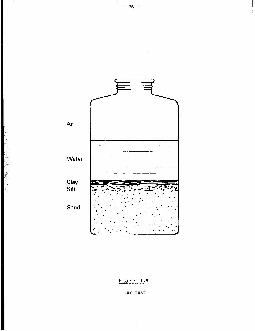
An estimate of the proportions of the various size fractions can be
obtained using the sedimentation jar test. Any straight-sided, flat-bottomed,
clear jar or bottle may be used. An approximately one litre capacity jar will
be adequate (figure 11.4). One-third of the jar is first filled with
broken-up soil. Clean drinkable-quality water is then added until the jar is
nearly full. The content of the jar is next mixed up, one hand covering its
mouth to avoid spilling. The soil is then left to settle for an hour, shaken
again and allowed to settle a second time. An hour later, the depth of the
separate layers can be seen and measured. The bottom layer consists of sand
and any coarser particles. The medium layer consists of silt and the top
layer of clay. Often, the top two layers will merge together. The settlement
of the clay fraction may be slow with some soils. The use of salty water for
this test will flocculate the clay and help it to settle, thus giving a
clearly defined level in the bottle which can be measured more easily.
Where laboratory facilities exist, a wet sieving process may be used to
estimate the quantities of various sizes of sand. The soil is first washed
through a nest of sieves of increasingly fine mesh, and the quantities
retained on each sieve are dried and weighed. The difference between the
weight of these fractions and that of the initial sample is then equal to the
weight of silt and clay. Further information about the composition of these
finer materials can be obtained using a sedimentation method (the Andreason
pipette) or a hydrometer method. Details of these and other methods are
described in British Standard Methods of Test for Soils for Engineering
Purposes - BS 1377:1975 (18).
- 26 -
Air
Water
Clay
Silt
Sand
I I -
-.-
Figure II.4
Jar test
- 27 -
Soil used for the production of bricks by traditional methods should
contain the following:
- 25 per cent to 50 per cent of clay and silt; and
- 75 per cent to 50 per cent of sand and coarser material.
The soil should preferably contain particles of all sizes
III.2 Plasticity and cohesion
If the moistened soil is rolled by hand (on a flat surface) into a
cylinder, a sharp break of the latter when pulled apart indicates a very sandy
soil with low plasticity(7). On the other hand, the soil may be considered
adequate for brickmaking if the cylinder elongates to the point of forming a
neck before breaking
Another test consists of preparing a long cylinder of 10 mm diameter and
letting it hang unsupported while holding it from one end. The length of
cylinder which breaks off will provide fairly accurate information on the
properties of the soil. The breaking-off of a piece of cylinder of 50 mm or
less will indicate that the soil is too sandy for brickmaking. In this case,
it will be necessary to add some fat clay or ant hill material to the soil. 'I
On the other hand, the breaking-off of a piece of 150 mm or more will indicate
the presence of too high a proportion of clay, /I necessitating the addition of
sand or grog to the soil. A soil adequate for brickmaking will require that
the length of the broken-off piece of cylinder is between 50 mm and 150 mm
(191.
The properties of the wetted soil will depend upon the moisture content.
A ball of suitable soil containing the correct amount of water should break
into a few pieces when dropped from the held-out arm on to hard ground. On
the other hand, a flattening out of the ball will indicate that the soil is
too wet, while the breaking of the ball into a large number of small pieces
will indicate that the soil is too dry. Some more precise assessment of
plastic properties can be obtained by simple laboratory tests. The soil
should be mixed up with an excess of water to make a very runny paste or
slip. The latter is then poured on a dry porous plastic plate, and mixed
continuously with a spatula or knife. As water is absorbed by the plate, the
soil will become less liquid and new incisions made with the knife will take
longer to close. Once an incision remains open, approximately 5 g of material
should be taken from its vicinity and weighed immediately. The sample is then 0
weighed again after a few hours' drying in an oven at 110 C. The moisture
content can thus be calculated as percentage of the dry weight of clay. This
percentage is termed the liquid limit of the soil.
- 28 -
Some small pieces of the clay may be removed from the plate and rolled by
hand of a flat-glass plate in order to make filaments approximately 3 mm in
diameter (figure 11.5). At first, long filaments may be fashioned easily.
Then, as the soil dries out there will come a point when they just start to
crack longitudinally and break up into pieces approximately 10 mm long. Once
this occurs, approximately 5 g of such pieces should be weighed, oven dried,
and weighed again to determine the moisture content as a percentage of the dry
weight of clay. This percentage is termed the plastic limit of the soil.
The difference between plastic and liquid limits is the plasticity index.
When more advanced facilities are available the liquid limit should be
determined with the cone penetrometer, described for example in BS1377 (see
section 111.1). In this test, the penetration of the point of an 80 g metal
cone having an apex of 30' is measured as it rests for 5 seconds on the
moistened soil. From a series of readings for different moisture contents the
liquid limit is determined as the moisture content which gives a 20 mm
penetration. The test for estimating the plastic limit is the same as that
described above.
Several other testing methods are used in well-equipped laboratories (17).
Soils with a low plasticity index will be difficult to handle for
brick-moulding: the green brick will distort after demoulding if the soil
contains a small excess of water while the soil will be too stiff to mould if
it lacks sufficient water. A high plasticity index is therefore preferred.
Soils with a high plastic limit will require a great deal of water before
they can be ready for moulding. Long drying is then necessary prior to
firing. A high plastic limit and very high liquid limit may indicate the
presence of montmorillonite, with its attendant moisture movement problems.
Thus, montmorillonitic soils may not be adequate for simple brickmoulding
methods as the latter require a relatively high moisture content. They need
either high compaction pressures on semi-dry mixes, or dilution with
non-shrinking materials. Montmorillonites may give rise to size changes in
the drying bricks as the humidity of the air varies naturally.
In a recently published book (20) reference has been made to an earlier
suggestion (21) that, within the plasticity ranges indicated in table 11.2, a
soil may be adequate for the production of bricks by traditional methods.
However, it may be possible to use materials with plasticity limits outside
the ranges shown in the table.
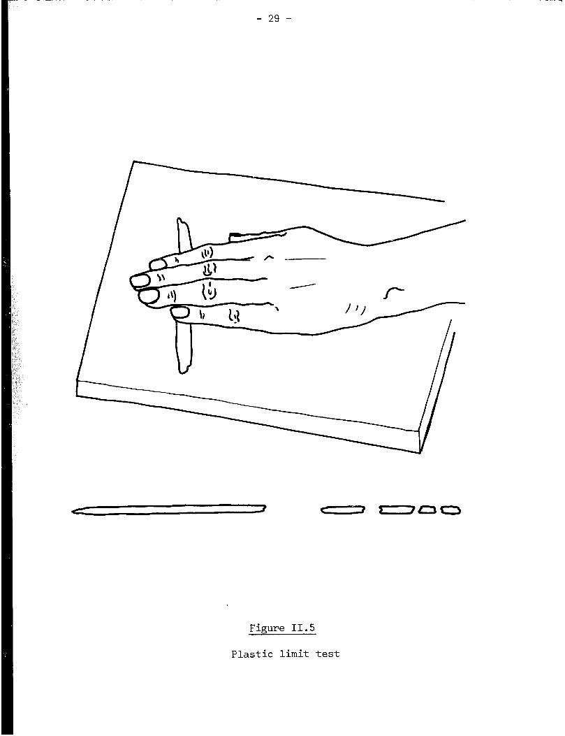
Figure II.5
Plastic limit test

- 30 -
Table II.2
Plasticity limits for good brickmaking soils
Plastic limit ....................... 12 to 22
Liquid limit ........................ 30 to 35
Plasticity index .................... 7 to 18
III.3 Mineralogy and geology
The mineralogist recognises the presence of certain minerals in the field
while the geologist identifies structures in the earth's appearance that will
assist in locating suitable raw materials sources.
The work of the mineralogist will consist largely of taking samples from
the field and examining them under the microscope in a laboratory. On the
basis of information from other tests, he may identify the components of a
soil and thus determine their suitability for brickmaking by the various means
available. In more advanced laboratories, the electron microscope (especially
the scanning electron microscope) will be a useful tool. Identification of
minerals will also be greatly assisted by X-ray diffraction analysis.
III.4 Chemical analysis
The colour of samples of materials obtained from field investigations
gives some indication of the composition of the soil. Red soils may be high
in iron, which can act as a flux. Very dark colours, or a musty smell in the
damp soil, may indicate the presence of organic matter: it may be possible to
use such soils, though their agricultural use should be given first priority.
Dried out encrustations on the surface of the ground indicate the presence of
soluble salts, which are best avoided for reasons given in Section 11.3.
A simple laboratory test for the presence of sulphates consists of
dissolving these salts and adding a solution of barium chloride. The forming
of a white precipitate will indicate the presence of sulphates. On the other
hand, chlorides can be detected by addition of silver nitrates. These
chemical tests could be done on site, with a small portable test kit. The
presence of calcium carbonate can be ascertained by the existence of lumps or
nodules which are likely to be white, or by effervescence from gas produced by
the addition of dilute hydrochloric acid to the soil. An estimate of the
quantity of carbonate has been suggested(7): 1 to 8 per cent in case of slight
bubbling; 8 to 16 per cent in case of pronounced bubbling; and 18 per cent in
case of sudden foaming.
In a properly-equipped laboratory, a full chemical analysis may be
undertaken, which, together with the mineralogical examination, can assist in
identifying the constituents as mentioned in section 11.3.

- 31 -
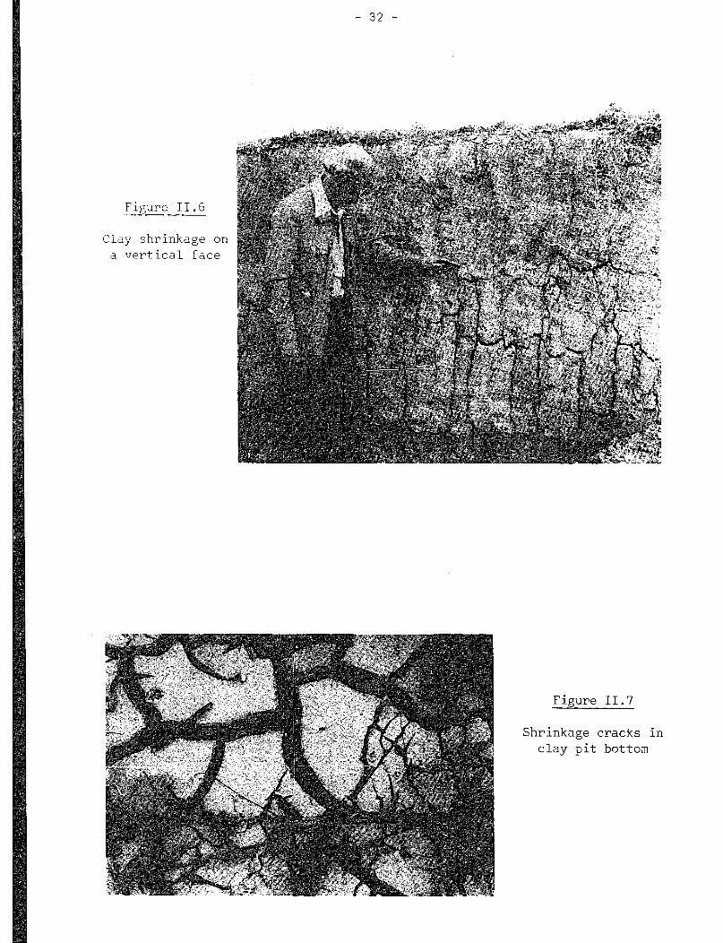
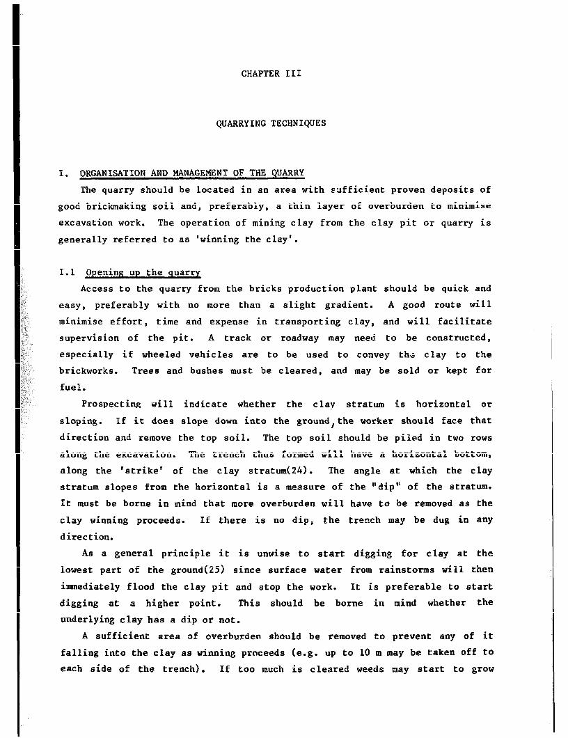
III. 5 Drying shrinkage
High clay content (recognisable in wet conditions by the stickiness of the
soil) is in dry weather, recognisable by the presence of shrinkage cracks in
exposed soil, in either vertical or horizontal faces (see figures II.6 and
11,7).
To obtain a measure of the shrinkage of a moist soil, which may seem
suitable for brickmaking, the most simple method is to mould a few bricks from
the soil and allow them to dry thoroughly. The length of the dried bricks and
of the moulds are then measured in order to obtain an estimate of the linear
drying shrinkage. The latter may be obtained from the following formula:
Linear drying shrinkage (per cent) = (Mould lenpth - final dry length) x 100
mould length
The appearance of the test bricks will give some indication of the
suitability of the soil for brickmaking. It is suitable if no cracks appear
on the surface. If some slight cracks appear it would be advisable to shorten
the soil by adding 20 per cent sand or grog. In case of extensive cracks, 30
per cent might be mixed in. Soil too lean for moulding will have to be made
more fat with other clays, or ant hill soil.
Generally , up to 7 per cent linear shrinkage may be tolerable, depending
upon the nature of the material and the rate of drying. If linear shrinkage
is more than 7 per cent shortening is advisable(22). In any case, it is
necessary 60 know the linear shrinkage in order to determine the exact size of
moulds needed for producing bricks of given dimensions.
If more organised test facilities are available, it would be advisable to
prepare special shrinkage bars. For this test, an open-topped wooden mould,
approximately 300 rnr> long by 50 mm deep and wide, should be made up by a
carpenter or a sufficiently skilled handyman (figure 11.8). The soil used in
the test 8hG :ld be dried, if not already so, and broken down. Large stones
should be removed. It is ,?en mixed with just sufficient water to bring it
near the liquid limit (i.e. pieces of the soil should be deformable yet retain
their shape). If time permits the soil should be covered, left overnight,
then mixed up again. The mould should be lightly greased inside to prevent
the soil from sticking. Some moist soil is then laid in the bottom, and the
mould tapped on the bench or ground to cause entrapped air bubbles to escape
from the soil. The mould should be filled in the way described above in
several stages, and excess soil struck off the top to leave a surface level
with the surface of the mould. The soil should be dried slowly at first, at
room temperature. Once shrinkage appears to have stopped, it may be tipped
out of
- 32 -
Figure II.6
Clay shrinkage on
a -7ertical face
Figure II.7
Shrinkage cracks
clay pit bottom
in

//-
---- m. _ - / - --
- _ --
--- - - - --
- - --- - \
- -- --
c \
0 0
0 8
e 1 r. .c-! i - : ‘. . ; _’ - m,.ll.l. . I.. . . +. *s ,. ‘. ._ ‘,
- -- ..: ., 4 ---
/@--
-- ,
--i
-.:- c -p --- . .
!. . . ---
a -m--w - \- --A
.*.. YY-’
n-u-, ;
/ .L .
Figure II.8
Shrinkage mould

- 34 -
the mould and dried in an oven at 11O'C. The linear shrinkage may then be
calculated as indicated above.
III.6 Firing shrinkage
Some shrinkage during firing is inevitable. From 6 to 8 per cent linear
shrinkage is desirable (5,7). The simplest field test to measure firing
shrinkage is to burn a whole batch of bricks.
Measurements of firing shrinkage are more readily obtained in the
laboratory than in the field. Small bars should be moulded, dried, measured,
then fired to various temperatures in a laboratory furnace. They are then
cooled and re-measured to calculate the linear firing shrinkage. A special
furnace has been designed for this test. It requires only one sample, since
it has a horizontal silica rod whose movement is measured outside the furnace
as the temperature rises. A 'gradient' furnace of uneven temperature
distribution can also give useful information.
CHAPTER III
QUARRYING TECHNIQUES
I. ORGANISATION AND MANAGEMENT OF THE QUARRY
The quarry should be located in an area with sufficient proven deposits of
good brickmaking soil and, preferably, a thin layer of overburden to minimise
excavation work. The operation of mining clay from the clay pit or quarry is
generally referred to as 'winning the clay'.
I.1 9ening up the quarry
Access to the quarry from the bricks production plant should be quick and
easy, preferably with no more than a slight gradient. A good route will
minimise effort, time and expense in transporting clay, and will facilitate
supervision of the pit. A track or roadway may need to be constructed,
especially if wheeled vehicles are to be used to convey thG clay to the
brickworks. Trees and bushes must be cleared, and may be sold or kept for
fuel.
Prospecting will indicate whether the clay stratum is horizontal or
sloping. If it does slope down into the ground,the worker should face that
direction and remove the top soil. The top soil should be piled in two rows
along the excavation. The trench thus formed will have a horizontal bottom,
along the 'strike' of the clay stratum(24). The angle at which the clay
stratum slopes from the horizontal is a measure of the "dip'" of the stratum.
It must be borne in mind that more overburden will have to be removed as the
clay winning proceeds. If there is no dip, the trench may be dug in any
direction.
As a general principle it is unwise to start digging for clay at the
lowest part of the ground{251 since surface water from rainstorms will then
immediately flood the clay pit and stop the work. It is preferable to start
digging at a higher point. This should be borne in mind whether the
underlying clay has a dip or not.
A sufficient area of overburden should be removed to prevent any of it
falling into the clay as winning proceeds (e.g. up to 10 m may be taken off to
each side of the trench). If too much is cleared weeds may start to grow

- 36 -
and will have to be cleared again. Clay may then be dug to a depth of a few
metres, along the centre line of the exposed area. The actual depth will
depend upon the adopted method of digging and the nature of the material
extracted. Further material is then obtained by widening this deeper trench a
small amount at a time. Eventually, it will be necessary to remove more
overburden. This unwanted material may conveniently be used to fill the
first-opened part of the trench once all the useful clay has been excavated.
If good clay does extend lower down, it might be extracted at a much later
date or by the method of ‘benching’ or ‘terracing’ (which is the working of
two or more clay faces at different depths at the same time).
I.2 Operating the quarry
Safety
It is important to bear safety in mind in the clay pit. Clay is very
slippery when wet. Thus steeply sloping paths and access routes should be
avoided. Steep drops into the pit would be hazardous. Damp clay is not
stable at a near vertical face. Consequently , a whole portion of the material
may undergo a rotational slip, into the bottom of the pit. For this reason,
it is advisable to slope back or ‘batter’ the faces of the pit as they are
dug. The latter should not be too high.
Water
If flooding of the pit bottom becomes a problem, the water may be drained
away through a downhill channel. If this is not possible, a sump must be dug
in the pit bottom to collect the excess water. The latter may then be removed
from the sump by pumping or with buckets. This water may be contaminated with
soluble salts present in the ground. Thus, it would be unwise to use it in
the subsequent brickmaking process, unless tests show that it does not contain
salts. In countries having a wet season or monsoon, the quarry may need to be
abandoned until the rainwater is drained off.
Rejection of impurities and reinstatement
As digging proceeds, the workers should discard any plant roots, stones,
limestone nodules or harder clay inclusions since they would cause problems in
subsequent processing. Any pockets of unsuitable soil should be removed
rather than left in place and the pit should be kept tidy. The top soil
should be returned ultimately, on top of discarded material into the
worked-out part of the quarry. Crops may thus be grown again. This is the
case, for example, in Madagascar where the most exploited clays for
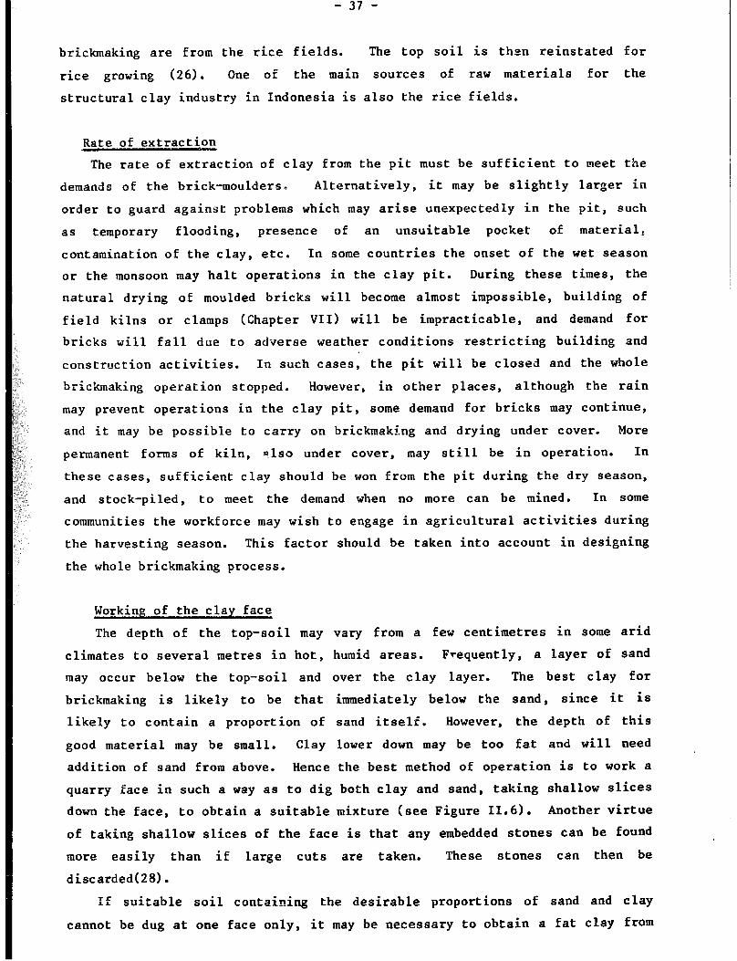
brickmaking are from the rice fields. The top soil is then reinstated for
rice growing (26). One of the main sources of raw materials for the
structural clay industry in Indonesia is also the rice fields.
Rate of extraction
The rate of extraction of clay from the pit must be sufficient to meet the
demands of the brick-moulders D Alternatively, it may be slightly larger in
order to guard against problems which may arise unexpectedly in the pit, such
as temporary flooding, presence of an unsuitable pocket of material,
contamination of the clay, etc. In some countries the onset of the wet season
or the monsoon may halt operations in the clay pit. During these times, the
natural drying of moulded bricks will become almost impossible, building of
field kilns or clamps (Chapter VII) will be impracticable, and demand for
bricks will fall due to adverse weather conditions restricting building and
construction activities. In such cases, the pit will be closed and the whole
brickmaking operation stopped. However, in other places, although the rain
may prevent operations in the clay pit, some demand for bricks may continue,
and it may be possible to carry on brickmaking and drying under cover. More
permanent forms of kiln, also under cover, may still be in operation. In
these cases, sufficient clay should be won from the pit during the dry season,
and stock-piled, to meet the demand when no more can be mined. In some
communities the workforce may wish to engage in agricultural activities during
the harvesting season. This factor should be taken into account in designing
the whole brickmaking process.
Working of the clay face
The depth of the top-soil may vary from a few centimetres in some arid
climates to several metres in hot, humid areas. Frequent ly , a layer of sand
may occur below the top-soil and over the clay layer. The best clay for
brickmaking is likely to be that immediately below the sand, since it is
likely to contain a proportion of sand itself. However, the depth of this
good material may be small. Clay lower down may be too fat and will need
addition of sand from above. Hence the best method of operation is to work a
quarry face in such a way as to dig both clay and sand, taking shallow slices
down the face, to obtain a suitable mixture (see Figure 11.6). Another virtue
of taking shallow slices of the face is that any embedded stones can be found
more easily than if large cuts are taken. These stones can then be
discarded(28).
If suitable soil containing the desirable proportions of sand and clay
cannot be dug at one face only, it may be necessary to obtain a fat clay from

- 38 -
one face and sand or sandy clay from another. This has often been done as,
for example, near Mombasa in Kenya, where material from two faces has been
mixed in the pit bottom prior to use. If the material varies horizontally
(i.e.from one place to another) two separate faces in the pit, or two separate
pits, might be worked simultaneously. If the material varies vertically (i.e.
a,t different depths), two faces can be operated by benching (see section 11.2).
Record-keepin
For later reference, a note-book should be kept for recording. progress,
and any significant happenings in the quarry. A map should be made of the
quarry, showing the position of original test holes or pits, the depth of .
clay, and other major features such as streams, tracks, large trees and the
brickworks if adjacent. The position of the clay-pit face should be drawn on
the map every few months, and the date written on the line representing the
face. If the floor of the pit is dug a second time or if benching is used, a
second colour could be used to update the map. This will assist in an orderly
exploitation of the reserve: haphazard digging is wasteful of material and
effort(27). The rate of ingress into the reserve should be clearly visible,
and if problems or complaints arise with the finished bricks, the fault may be
traceable to a cause in the pit. The extent of any problem materials in the
pit should be marked on the map. The supervisor should check constantly the
work at the clay face and inspect the material being won to ascertain that it
is suitable and does not contain deleterious materials.
II. METHODS OF WINNING THE CLAY
Two basic methods are available ; mechanical winning and hand-digging.
These are briefly described below.
Mechanical winning
Mechanical methods such as the use of the drag-line and multi-bucket
excavator are mostly appropriate for the largest-scale brickmaking
operations. It is most unlikely that even a face shovel (figure 111.1) could
be justified in works of the size considered in this memorandum, unless it is
available on hire from a nearby depot for a short period of time each year,
(e.g.in order to build a stock pile). It seems unlikely that mechanical
winning could be economical for output of less than 14,000 bricks per day(22).

- 39 -
On the other hand, the more commonly available and versatile bulldozer
could have a place in the laborious task of clearing overburden on infrequent
occasions. It might be brought in on hire, or when available from nearby road
construction or other civil engineering works (e.g. against payment of a fee).
Most of the clay resources utilised by the small-scale manufacturer are
likely to be of the soft plastic type. In some areas, when only hard shales
are available, blasting might be undertaken occasionally to loosen material
from the quarry face.
II. 2 Hand-diggin&
Hand-digging has been widely used even for medium-size production plants,
because of its versatility in dealing with all clays from soft muds to shales
or even with ant hills. Hand-d igging can also be adjusted to various types
of work, and allows workers to sort out unwanted stones, limestones, roots,
etc. It also avoids large amounts of capital investment, the stocking of
spares and the organisation of maintenance of machinery. In many situations,
hand-digging may be the only possible means of winning clay.
The rate of winning clay will depend upon the type of clay, the nature of
the pit and the productivity of labour. Productivity rates for one man
digging enough clay for the production of approximately 3,500, 1,500 and 4,000
bricks per day have been estimated(5,25,8). However, these estimates are not
strictly comparable as some of them include an element for the transport of
clay over a short distance. Measurement of shovelling rates in the American
mines(29) indicated an optimum working day of 6.5 hours. Longer working hours
result in lower outputs.
Once clay has been dug, there will be a natural reluctance to reject any
which may prove unsuitable, especially after the hard work of winning it. In
particular, the workers paid according to quantity excavated may be reluctant
to reject unsuitable material. Hence the importance of supervision,
inspection and quality control.
If the face is benched, the separate levels need be only 1 m different(25)
and 0.5 m wide(5), especially if materials from two or more levels are to be
mixed. This can be done by throwing all materials down to the lowest level
for mixing, and subsequent transportation away to the works.
The details of working the pit must be decided locally. For example, at
Asokwa in Ghana (figure 111.2) the clay was hand-dug from a face which was
approximately 2.5 m high in places(30).
Steel bladed, medium-weight spades are well suited for digging plastic
I
clays. Preferences in blade design vary from country to country. It is,
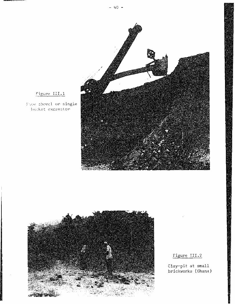
- 40 -
Fieure III.1
i‘ l!.‘t‘ shovel or single
bui:he t t~xcavator
Figure III.2
Clay-pit at small
brickworks (Ghana)

- 41 -
no weve r , recommended to use narrow and slightly conical blades for the digging
of this type of clay. The handle of the shovel should be shorter whenever
the foot is used on the top of the blade. In places where this is not done,
the handle is traditionally very long.
If hard, dry clays are to be won (figure 111.3) it may be necessary to
loosen them from the face with a pick, then shovel the material away.
In many countries, the hoe and mattock are more generally used and are
suitable for winning clay.
III. TRANSPORTATION TO THE WORKS
In large works, clay is conveyed from the pit in various ways, inc’luding
the use of lorry or truck, large dumper truck, small-gauge railway systems,
aerial ropeway or belt conveyor. Capacity, capital cost, maintenance and
repair militate against the use of these methods for the smaller works.
While heavy transport equipment may not be suitable, the use of a small
diesel-powered dumper or a front-end loader may become feasible on a hire
basis. Similarly, an agricultural tractor may be used to haul a loaded
trailer of clay. Alternatively, a draught animal may be useful for pulling a
trailer if the road is not too steep and muddy.
The wheelbarrow is a versatile and low-cost device for moving clay. It
need not be all-steel or specially imported and can be locally produced from
available materials. It can be taken from the clay face to any desired point
at the plant site, on a narrow path or a plank on muddy ground (figure 111.3).
The larger the wheel, the more easily the barrow will pass over irregularities
in the ground. The wheel should be as close to the load as possible in order
to take the weight off the hands. The handles should also be approximately 50
mm lower than a standing person’s palms when the barrow is at rest on the
ground. Thus, the arms are just slightly crooked when the barrow is wheeled.
A simple aid for carrying clay and other materials is the litter (figure
111.4). Its use by two people avoids twisting the body. Large loads may be
carried over rough terrain, or up steep slopes. It may be fabricated easily by
unskilled labour using cheap, locally available materials.
The most simple devices for transporting clay are the basket and headpan,
both of which will be available in many communities.

- 1+2 -
Figure III.4
Litt,?r for c.3rryinF, wet clay (Sudan)

:
CHAPTER IV
CLAY PREPARATION
Good bricks of consistent quality and free from defects will only be
obtained if the materials used are of suitable and uniform nature. Only
rarely will such a material be won directly from the clay pit. Commonly, some
preparation and pre-processing is necessary to remove unwanted inclusions, add
non-clay materials, or mix the materials for uniformity. In most cases, water
must be added in order to bring the clay to a suitable consistency for forming
into shape.
Adequate careful preparation will mitigate the following problems which
might otherwise arise with the bricks.
Overall cracking on the surface due to the use of too high a proportion
of clay fraction in the mix. This may be minimised by adding sand or
grog.
Localised cracking over a hard piece of clay (figure IV. 11, or a large
stone; mitigated by crushing or removing such inclusions.
Limeblowing (figure IV. 2) which may be avoided by removing the larger
limestone pieces and reducing any remaining limestone to less than 2 mm
across pieces, or smaller pieces if the quantity of limestone is high.
Indian research(31) suggests that the addition of 15 kg common salt
added to the clay per 1,000 bricks should minimise limeblowing.
Low green strength of dried brick, possibly due to insufficient clay in
the mix.
Lack of plasticity, making the forming process difficult; also due to
insufficient clay in the mix.
Non-uniformity of size, shape and strength due to insufficient mixing of
the materials.
Efflorescrnce and sulphate attack of cement-based mortars (see Chapter
VIII), which might be reduced by rejecting surface clay where the salts
may have accumulated naturally. There is also an expensive option of
chemical treatment with barium carbonate. It is extremely difficult to
wash salts out of clay, as it is difficult to mix the latter with water.
Furthermore, large quantities of water will be required for this purpose.

,
P
- hh -
- 45 -
Efflorescence on bricks made from clay containing high concentrations of
soluble salts is shown in figure IV.3 In some circumstances, salts
crystallise beneath the surface, buidling up stresses which can force
flakes to spa11 from the surface as shown in brickwork in a boundary
wall in India (figure IV.4).
I. MAIN CLAY PREPARATION PHASES
Clay preparation includes the following operations:
- sorting (or picking) and washing;
- crushing or grinding;
- sieving or screening;
- proportioning;
- mixing, wetting and tempering.
A whole range of motor-driven machines is available for these operations,
including belt-conveyors, jaw-crushers, kibblers, hammer mills, grinding pans
(both wet and dry), rolls, de-stoning machines, vibrating wire screens,
proportioning feeders, double-shafted trough mixers, and pug mills. However,
few of these capital-intensive items will be appropriate to the type of
production described in this memorandum. In a labour-intensive set-up, a
mixing machine may be the most useful piece of equipment if diesel or electric
power sources can be used. Animal power may also be worth considering.
It is best to prepare clay in a very dry or a very wet condition. Damp
clays are difficult to crush, they stick on sieves, are awkward to handle and
require much power to mix.
II. SORTING
An essential part of clay preparation is that carried out in the pit.
This includes the discarding of unsuitable pockets of soil, roots, stones,
limestone nodules, etc. and the winning and preliminary mixing of clayey and
sandy materials. Visual inspection of the clay in the works is not easy to
carry out or enforce, but is done on a routine basis whenever the clay can be
moved on a narrow conveyor belt past workers who pick off any unwanted
material. It is advisable to have the supervisor check the clay coming into
the works from time to time. Unwanted materials detected at this or any
subsequent stage should be removed.
Where stones or limestone nodules constitute a particular problem they can
be removed in a washmill (see Section IV.3).

- 46 -
Figure IV.3
White efflorescenc :e on
brickwork (Middle East)
Figure IV.4
Flaking of the type
produced by soluble salts
(India)
- 47 -
III. Crushing
In the tropics, clay will generally be dry when won from the pit. Thus the
centres of large lumps will be difficult to wet. Non-uniform material is
likely unless the dry clay is first crushed to less than a few millimetres
across. Where capital cost is justified by a sufficiently large production
scale, and where power sources are reliable, crushing rolls may be useful.
Figure IV.5 shows crushing rolls in Ghana.
III. 1 Manual pounding and the. hammer hoe
Manual pounding with a hammer or punner may be used in small works but is
very laborious. There is a tendency for already broken pieces to be compacted
again, forming a hard lump which prevents the tool from breaking fresh
material. It is thus necessary to clear away material as soon as it is
broken. In favourable circumstances, two tonnes might be prepared per day by
a team of four men (e.g. enough for 1,000 bricks).
The hammer-hoe (figure IV. 61, which is used in Malawi, is a useful
dual-purpose tool, having special uses not only in the works, but also in the
clay pit. Material can be won, turned over, and mixed with the hoe. If hard
lumps are found in the mix, it is not necessary to exchange tools as a
half-turn rotation of the handle will bring the hammer into position for
breaking the lumps.
III.2 The pendulum crusher
A labour-intensive crushing machine has been developed by the Intermediate
Technology Workshop in the United Kingdom especially to meet the needs of the
small-scale brick-maker as identified in an earlier survey(l0). It is easily
built from mild-steel sections, and works on the pendulum principle. The
soil, which is placed in a feed hopper at the top of the pendulum, comes into
contact with a static grinding head and a curved moving grinding head. The
latter is attached to the top of the heavy pendulum which is kept swinging by
two people (figure IV. 7). The moving head is studded with protruding bolt
heads which entrap and crush clay as the head rotates in a downwards
direction. Ground clay falls through by gravity on to a built-in sieve which
can be of any desired T.:sh size. On the upward return move, any remaining
clay is cleared from , -he grinding surfaces prior to the next downward swing,
so that a slight dampness of the clay is not a great problem. Figure IV. 8
shows details of the components of the crusher.
To operate the machine, two men start the pendulum swinging. Once the
latter has reached a maximum angle, a third man starts feeding material. If
exceedingly hard pieces are encountered or if, for example, a steel tool is

- 48 -
Figure IV.5
Motor-driven crushiq rol Is (Ghana)
Figure IV.6 -
Hammer hoe
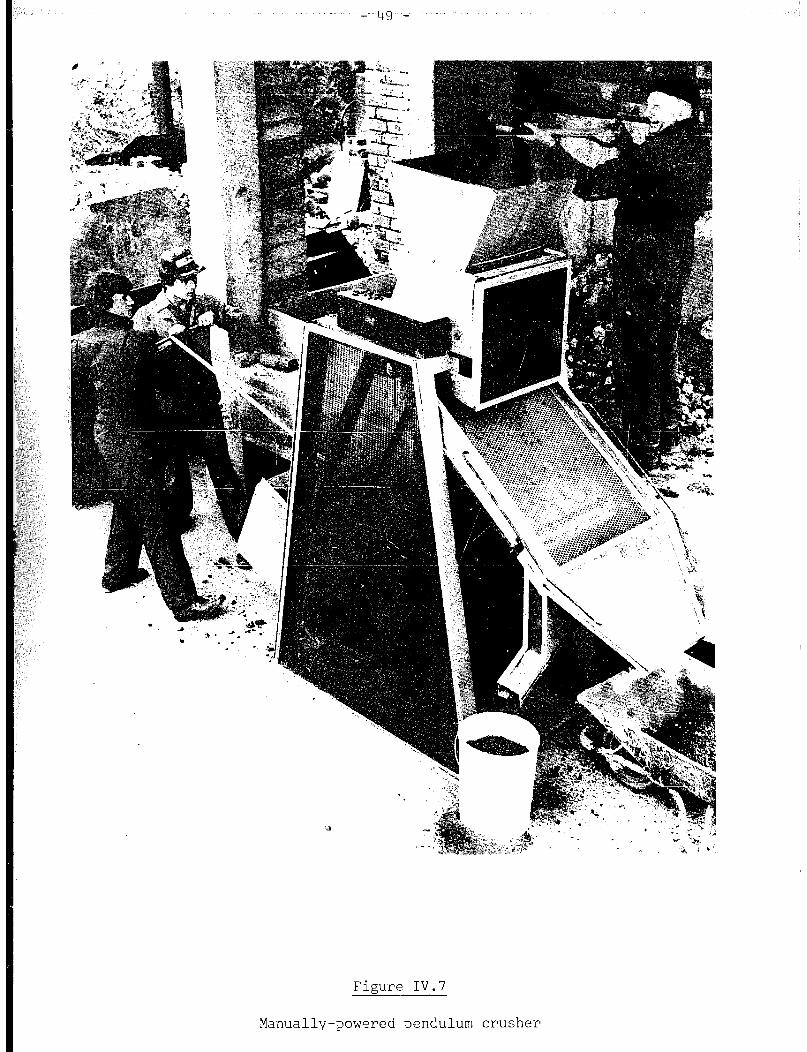
- 49 -
Figure IV.7
Manually-powered pendulum crusher
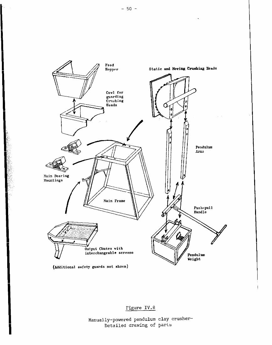
- 50 -
Crnshin,
Static and Moviag Cmrhing Heads
hln.dingg9 .,“--I---_
Plain Fkame
Y
a
n iii
0
0
Pendulum Arm9
Push-pull
interchangeable Screens ndulum iglit
(Additional safety guards not sholsn)
Figure IV.8
Manually-powered pendulum clay crusher- Detailed drawing of parts

- 51 -
accidentally dropped in the hopper, the grinding heads will not be damaged,
nor will the machine stop since the pivot bar of the pendulum can run up in
the rectangular bearing box, as a safety measure. The whole machine is
guarded to minimise the risks to operators. A fourth man should be available
to remove the ground clay and return rejects from sieving to the pile of clay
yet to be crushed,
Periodically (e.g. each time the container is full of finely ground clay)
the operatives would be well advised to change tasks on a regular rotation,
moving between jobs as follows: 1: feeding clay; 2: pendulum handle (right
side) ; 3: pendulum handle (left side); 4: attending discharge and resting,
then back to feeding again.
An extensive series of tests has shown some variation of production rates
depending upon clay type< On averages a four man team may produce crtished clay
at a rate of 20 tonnes per day, (i.e. enough for 10,000 bricks). This was an
average for the easier alluvial and sedimentary clays. If harder shales are
used, enough material may be produced for 8,000 bricks per day. The same team
may also prepare a tonne of grog by crushing underfired bricks in 2.25 hours.
Occasional greasing of the bearing of the pendulum is the only servicing
necessary. Prom time to time the machine should be inspected for wear. The
pivots and the bolts protruding from the moveable head are the parts most
likely to deteriorate. They should be simple to replace when worn out.
The pendulum crushers, which have been operated in several countries, can
be fabricated from readily available steel sections. None the less,
entrepreneurs should first refer to the innovators for precise details before
adopting the method. Ready-made machines or sub-assemblies can also be
obtained from them (see Appendix IV). Manufacture under licence is being
arranged in several countries.
III. 3 Animal-powered roller
A traditional crushing method in India uses a heavy stone roller pulled by
a bullock over the dry clay. The latter is laid out in a circle at the
centre of which the axle for the roller is pivoted. Other draught animals
could perfirm this task.
IV. SIEVING
Crushed clay must be sieved to ensure that over-size pieces are not used.
These should be returned for further crushing. The finer the material the
better the quality of the brick. However, clay passing through a 5 mm sieve
should be satisfactory. The simplest device for sieving is a screen of wire
mesh, fastened on to a rectangular frame resting on the ground at one end and
supported on legs at the other at a 45’ angle to the ground (figure IV.9).

material to be for brickmaking
‘Reject size material to be re-crushed
Figure IV.9
Sieving

- 53 -
v. PRO-PORTIONING
The mixing of two different dry materials is best undertaken after
crushing and sieving . Quantities of clays, grog, sand, etc. should be
measured by volume since this method is generally much easier than weighing.
Measurement is advisable in order to get a consistent product quality.
Measures should be taken from each constituent in turn, to give a preliminary
amount of mixing.
VI. MIXING, WETTING AND TEMPERING
Dry ingredients may be mixed with hoes or spades. In addition to clay,
sand and grog, solid fuel may be mixed with the clay to assist with the
burning of the bricks (See Chapter VII). Mixing should be continued until no
difference of colour or texture can be seen from place to place in the pile.
For special purposes, where soluble sulphate salts constitute a problem,
barium carbonate (precipitated) may be added. A fixed quantity, such as 10 kg
per 1,000 bricks, may not be a priori recommended since it will depend on the
extent of the problem.
Water must be added to most soils, over the whole surface of the
spread-out material, or as each layer is deposited in a pile. Water should be
sprinkled with a watering can fitted with a rose spray, or a similar device.
Mechanical power may be used for the laborious task of mixing and kneading
the clay. Concrete mixers have a rotating drum with paddles attached inside.
The consistency of wet concrete is such that the paddles can just about pass
through, and any adhering concrete slips off when the paddles rise.
Consequently, only an extremely wet clay, too wet for brickmaking, could be
mixed in a concrete mixer as stiffer mixes will merely adhere to the paddles
and drum. For stiff mixes it is best to use a stationary container equipped
with rotating paddles or blades. This should be borne in mind by any person
attempting to design clay-mixing equipment. For example, an oil-drum rotating
on bearings fixed to each end will generally fail to achieve effective mixing.
A mot or-powered double-shafted trough mixer is ideal, and readily
available from major equipment suppliers. However, acquisition of this
equipment involves high capital investments. The capacity of this equipment
may also be too large for small production units. Single-shaft mixers are not
so efficient . Trough mixers need to be very strong and powerful, and may be
unsatisfactory if made of too thin a gauge steel and undersized bearings.
They are made and used in Ghana by a number of brickworks (32).

- 54 -
Much of the work of mixing water and soil may be avoided by the simple
expedient of waiting for the water to percolate right into the structure of
the clay. The thoroughly mixed dry constituents, having been wetted and piled
up as described above, should be covered with sheeting or sand to prevent
evaporation and drying. This long-term wetting process, known as “tempering”
or “souring”, allows chemical and physical changes to take place in the clay,
thus improving its moulding characteristics. These benefits may be achieved
within a day or two with many clays, though others (such as the harder shales)
may require weeks.
VI. 1 Pugmills
A pugmill is a most useful machine for mixing wet clay ready for
moulding. High capital-cost machines from the major suppliers of brickmaking
equipment have a series of angled blades rotating on a horizontal shaft within
a closed barrel. These blades mix the clay and force it out by an opening in
the barrel. Electric or diesel power are used for this type of machine
(figure IV. 10).
Cheap, animal-powered pugmills may also be produced locally. These
pugmills have been used for centuries (33) and continue to prove successful.
For example, they were in use in England a few decades ago(34), and more
recently in Turkey( 10). Indonesia may also start using these pugmills (27). .’
Animal-powered pugmills (See figure IV.111 are made of a strong circular metal
or wood tub, approximately 1 m high, with a vertical driven shaft in the
centre, fitted with near-horizontal blades. Wet clay is driven downwards by
the rotation of angled blades, gets cut and mixed by other blades and emerges
from a small hole near the base of the tub. Animals are yoked to a beam which
rotates the shaft (figure IV.12).
VI. 2 Foot-trew
A simple and labourintensive method of preparing the more plastic
fine-grained clays is foot treading. Clay can be trodden in the quarry, but
it is advisable to carry out this operation on a concrete or brickwork surface
at the plant site (figure IV.13). Ideally, a circular or rectangular surface
should be bounded by a 300 mm high upstand. The soil, straight from the
quarry if suitable, or after some crushing, is spread 50 to 100 mm deep on the
surface. If both fat and lean materials are needed, they should be layered.
All the constituents must be thoroughly wetted, turned over with hoes or
spades, and left covered up to temper for a few days. The workers then puddle
the clay by treading in it , mixing and working the water in. The total volume
of clay must be trodden systematically. It is advisable to turn it over with
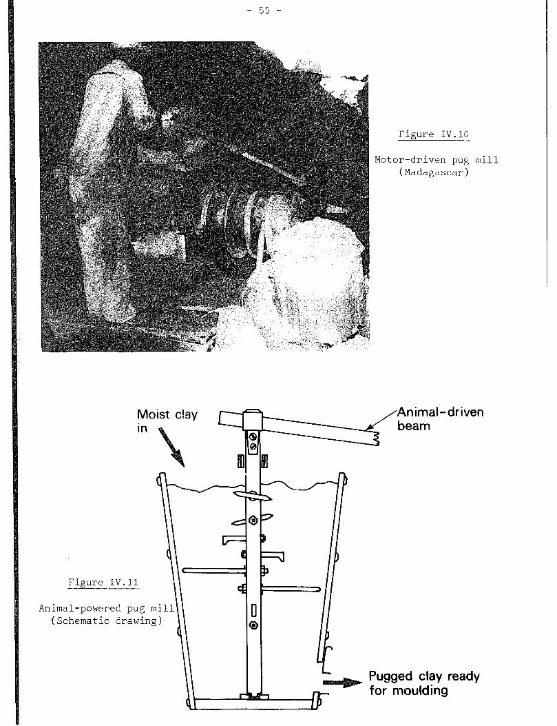
Figure IV.10 --
Moist clay Ir /--(=’ in
Figure IV.11 -.
Animal-powered pug mi
(Schematic drawing)
!4ot :or-drive n Pug (Madaga scar>
mill
Pugged clay ready for moulding

Figure IV.12
Animal-powered pug
(Tur key)
mill
- 56 -
, ,* ., I.
w .*
_.(- ‘: ‘.”
.
Figure IV.13
Foot-treading clay on
floor (Ghana)
concrete

- 57 -
hoes and retread it. The mix should not be too dry as it will be difficult to
move the feet up and down repeatedly. On the other hand,
if it is too wet, it will not be suitable for moulding. At best, foot
treading is a very tiring work. If any treader feels a stone in the clay, he
should pick it out, and discard it. Unfortunately, this is an operation which
is easy to neglect and difficult to check. Fortunately, a few stones left in
the clay will only damage a few bricks. ThUS, for practical purposea,
complete elimination of stones is not necessary for simple brick-moulding
techniques. However, if bricks were to be wirecut (Chapter V), to include
perforations, or to be made into extruded hollow blocks with thin walls the
presence of stones would create problems.
In practice, it may be possible to get the workforce together just before
the end of the working day in order to tread the wetted clay for the next or a
later day's moulding. Leaving the clay for a while may further improve the
moulding process.
VI.3 The washmill
The washmill is a labour-intensive method of cleaning clay in order to
free it from stones, limestone nodules and other large particles. It
requires fairly large quantities of water and produces a moulding material
with a fairly high moisture content. The clay from the pit is preferably
broken down prior to mixing with water in order to speed the process. A large
brick-built or metal tank approximately 1 m deep and several metres across is
filled to one-third of its height with the soil. Water is then added until it
is two-thirds full. The mixture is stirred to disperse the soil up to the
point where a clay slip or slurry is formed and the unwanted inclusions fall
to the bottom of the tank. The clay slip, with sand suspended in it, is then
run off into one of a series ~'f lagoons or ponds where it will settle. After
treatment of several loads of clay, the accumulated stones must be removed
from the bottom of the washmill. Weeks may be required for the clay to settle
in the lagoons, during which time the supernatent water can be run off a
little at a time over a simple, variable-height sluice, and re-used in the
washmill. Eventually, the last of-the water will be drained off and the solid
material will start to dry, though it must not dry completely. Once it can
bear a person's weight, the material can be re-dug. Cuts should be taken from
top to bottom to ensure an even mix of fine clay and sand at all times.
Washmills have been used with success in many places. One such washmill
was operated at Bricket Wood, in the United Kingdom, prior to developments
- 58 -
on the brickworks site by the Building Research Establishment. Recently, the
washmill has solved a particular limestone problem in India(351, and is widely
used at nearby Indore and other areas of Madhya Pradesh, where it is known as
the ‘ghol’ method.
The shape of the washmill is not import ant if the slip is stirred
manually * In this case it is easier to build a rectangular washmill. On the
other hand, the use of other power sources requires a circular tank. Animal
power could well be used for this purpose (figure IV.l/:>. The size of mill
will depend upon the nature and quantity of clay to be processed, the
proportion of impurities and the planned brick production rate.
The washmill achieves most of the stages of clay preparation.
VII. TESTING
Testing methods described in Chapter II could be applied to check if the
material is suitable or whether modifications need to be made. In practice,
this information is difficult to apply for a given batch of clay since the
latter must often be used before the test results are available. This
emphasises the need for careful preparation to produce a material of constant
properties, and the need to check the quality of the final product (Chapter
VII) and to relate any problems to clay preparation.

Outlet gate
Figure IV.14
Animal-powered washmill

CHAPTER V
SHAPING
I. DESCRIPTION OF BRICKS TO BE PRODUCED
This section will provide the main characteristics of the bricks covered
by this memorandum.
I.1 Size, shape and weight
In general, a brick should be of such a size and weight that it can be
lifted in one hand. In almost all cases, a brick is twice as long as it is
wide. Its height is usually one-third of its length (including the width of
one mortar joint added to each end of the brick.) For example, the dimensions
specified in the Indian Standard(36) are 190 x 90 x 90 mm and 190 x 90 x 40
mm. The 2~1 ratio is often adopted as it is highly suitable for bonding. The
brick height is a matter of choice. In some countries, it is standardised so
that it may fit to standardised dimensions of other components, such as window
frames. The British Standard Specification for Bricks(37) requires that they
be 215 x 102.5 x 65 mm or 225 x 112.5 x 75 mm if a 10 mm mortar joint is
added. The 11-hole machine-extruded perforated brick (figure V.1) made in
West Africa is too wide to be held in the hand. This type of brick may,
however, be required for special purposes.
Bricks produced in small-scale plants do not generally have holes. In
some cases, a frog is indented into one bed face. The single frog cannot be
assumed to increase wall strength, but may assist in moulding in some
circumstances. It may also shorten the drying time, slightly reduce the
amount of fuel for firing, and reduce weight for transportation. However, it

- 62 -
requires more mortar for wall building, especially if the brick is laid frog
up . Frogs may be made on both bed faces in some shaping processes.
Perforated bricks (figure V.l> are only produced by extrusion machines. They
have advantages similar to those listed for frogged bricks.
Bricks which are accurate in shape and size are good to handle, transport,
stack and build into a good wall with flat faces. If walls are to be
rendered, less material is required than if they had an irregular surface.
Furthermore, less mortar is required between accurately made bricks (see
Chapter VIII>.
Bricks of special shape may be produced, for example, for building wells
and circular chimneys, or for joining walls of different thicknesses without
silarp steps. Roofing tiles can also be made by similar methods. Big hollow
blocks and decorative screen blocks are produced by machine extrusion.
However, this memorandum concentrates on the production of brdlnary-shaped
bricks.
The size of the brick mould, die, etc. must be larger than the brick
specification to allow for drying and firing shrinkages.
I.2 Faults in bricks
A number of faults in the finished product can be attributed to bad
shaping. In extruded bricks, S-shaped cracks are caused by the
clay-impeller’s design or use. Saw tooth or dog-eared corners are caused by
poor lubrication of the die near the corners. Internal cracks along the line
of extrusion indicate an unequal extrusion rate in the centre as compared to
that on the edge. Uneven heights of extruded bricks may be due to uneven
spacing of cutting wires. Drag marks on cut surfaces are often due to dirty
cutting wires in extruded and hand-made products. Irregular sizes and shapes
of hand-moulded bricks may oe due to inaccurate and bent moulds. Weaknesses
may result from layers of sand being folded into the clay. Odd flashes may
result from old clay stuck in narrow gaps of the mould or from overfilling of
the would. Missing corners, bent bricks, trapezoidal shapes and indentations
may be due to incomplete filling of the mould, careless demoulding, setting
down the green bricks sharply on the drying ground, squashing the demoulded
bric’ks too tightly between pallets or marking them with the fingers.
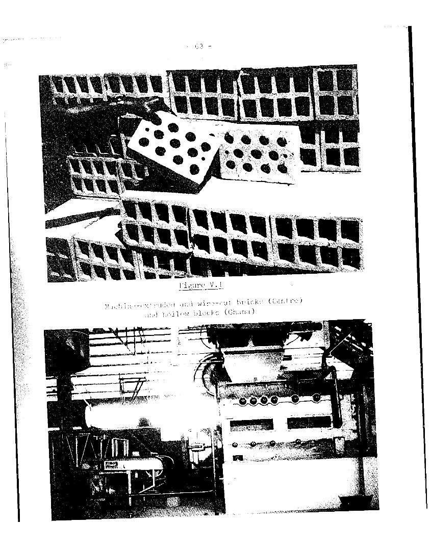
--
I;~---,..,-----
---

- 64 -
II. METHODS OF SHAPING
It has often been thought that machine-made bricks are better than
hand-made bricks. This, however, should not be necessarily the case if
hand-moulding is carried out with care. Furthermore, a comparative study of
the economics of production in developing countries (see Chapter X) clearly
indicates that hand-made production is still competitive in spite of
technological developments.
Ready-made equipment may be imported, for both large-scale plants (e.g.
equipment for a highly automated plant imported from Europe, by Ghana, shown
in figure V.2) and small-scale units. In the latter case, equipment is used
in a very few operations which complement the predominant use of labour.
Mechanised shaping methods will be considered briefly first, followed by
the labour-intensive shaping methods. Finally, simple and cheap methods of
assisting the hand-moulding process will be described.
The choice of shaping method should take into consideration the following:
capital cost and expected life of equipment; maintenance and spares service;
availability and cost of fuel (including reliability of electricity supply);
scale of production in relation to raw materials supply; and market demand at
time of installation and throughout the planned life of the installation.
These points will be amplified in Chapters X and XI.
II.1 Mechanised shaping methods
11.1.1 Wire cut bricks
A method of producing machine-made bricks, which is commonly used in
developing countries, is that of extrusion from an auger machine. This method
is, for example, used in Madagascar (see figure V.3). In this machine, which
is similar to a horizontal pugmill, the clay is impelled by an Archimedean
screw. Taut wires cut brick sizes off the continuous column of clay (figure
V.4 shows an automated cutter, manufactured in the Federal Republic of Germany
and used in a brickmaking plant in Ghana).
This type of equipment is often imported by most developing countries.
One exception is India where research 'was carried out into the construction of
indigenous plants for making 20,000 bricks per day(38). Several such plants
have since been built and operated(39). A supplier list of equipment is
provided in Appendix IV. However, the wire cut-process is used at scales
outside those considered in the memorandum.

Figure V.3
Wire- ,cutter and wire-
cut bricks (Gha Ii-m)
Figure V.4

- 66 -
11.1.2 Soft mud process
Soft alluvial clays, such as those suitable for hand-moulding, may be
processed by the soft-mud process. One of the smallest machines available
produces approximately 14,000 brieks per day, a scale of production larger
than those considered in this memorandum. This particular machine, originally
made in the United Kingdom as the Berry Machine, was bought up by another
company which is now producing it in the Netherlands (see Appendix IV). It
has a horizontal pugmill followed by a set of cams which force moist clay
through the side of the containing barrel into a quartet of iron-clad wooden
moulds (see Figure V. 5). To prevent clay from sticking, moulds are sanded.
This can be done by hand. The whole process is fairly labour-intensive. The
pugmill section alone could be used to prepare clays for hand-moulding.
11.1.3 m
Bricks can be pressed, but commercially available machines are expensive
and have high production rates. However, smaller hand-powered machines have
been used in the past (33) and could still be employed, provided that the
extra cost and time could be justified by an improvement in quality.
II. 2 Hand-moulding
In the earliest techniques, soil was shaped by hand into lumps. The use
of a mould to give shape to the soil resulted in more accurate and better
bricks. Wood moulds should be soaked in oil for a few days before use. They
are best made from a hard wood, shod on corners with iron or steel, and
preferably lined with metal sheet. A handle bar is needed at each end. Metal
moulds must be of a sufficient thickness to resist bending in use.
II. 2.1 Slop-moulding
In s lop-moulding , a very wet mix of clay is thrown into a wetted
bottomless mould of wood or metal (figure V.6) as it rests upon a wooden
pallet. Excess clay is scraped off either with the hand or with a striker (a
straight wooden bar; see figure V.7). As the mix is very sloppy the mould
cannot be removed until the brick has sufficiently dried or started to
harden. Usually, the mould is removed immediately and returned to the
moulding bench, re-wetted in a tub of water, and used again. In some
instances, moulding is done on the ground without the use of pallet (40).

- 67 -
Prepared soft
Moulded brick OUT
Figure V.5
Soft mud brickmoulding machine
nPtY
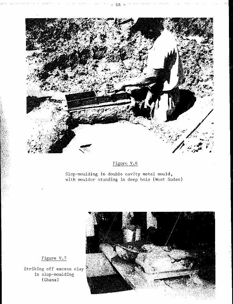
Strikil
in
Figure V.6 --
Slop-moulding in double cavity metal mould,
with moulder standing in deep hole (West Sudan)
Figure V.7 --
ng off excess c
slop-moulding
(Ghana)
lay
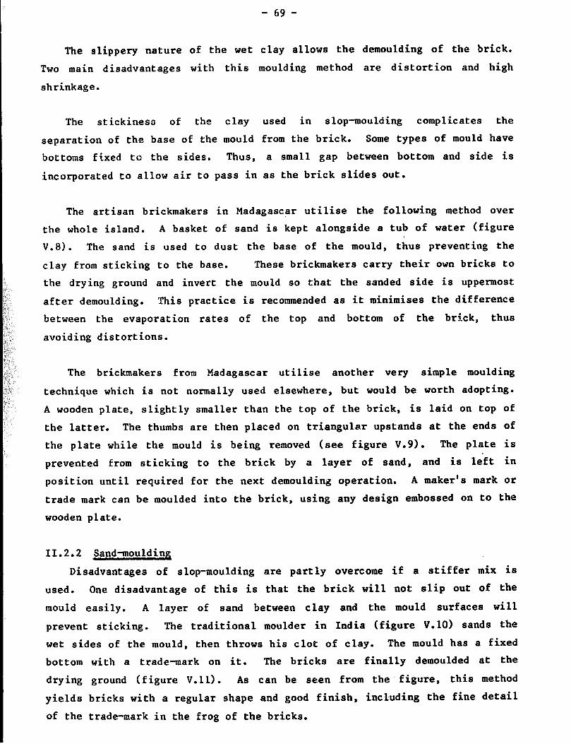
- 69 -
The slippery nature of the wet clay allows the demoulding of the brick.
Two main disadvantages with this moulding method are distortion and high
shrinkage.
The stickiness of the clay used in slop-moulding complicates the
separation of the base of the mould from the brick. Some types of mould have
bottoms fixed to the sides. Thus, a small gap between bottom and side is
incorporated to allow air to pass in as the brick slides out.
The artisan brickmakers in Madagascar utilise the following method over
the whole island. A basket of sand is kept alongside a tub of water (figure
V.8). The sand is used to dust the base of the mould, thus preventing the
clay from sticking to the base. These brickmakers carry their own bricks to
the drying ground and invert the mould so that the sanded side is uppermost
after demoulding. This practice is recommended as it minimises the difference
between the evaporation rates of the top and bottom of the brick, thus
avoiding distortions.
The brickmakers from Madagascar utilise another very simple moulding
technique which is not normally used elsewhere, but would be worth adopting.
A wooden plate, slightly smaller than the top of the brick, is laid on top of
the latter. The thumbs are then placed on triangular upstands at the ends of
the plate while the mould is being removed (see figure V.9). The plate is
prevented from sticking to the brick by a layer of sand, and is left in
position until required for the next demoulding operation. A maker’s mark or
trade mark can be moulded into the brick, using any design embossed on to the
wooden plate.
11.2.2 Sand-moulding
Disadvantages of slop-moulding are partly overcome if a stiffer mix is
used. One disadvantage of this is that the brick will not slip out of the
mould easily. A layer of sand between clay and the mould surfaces will
prevent sticking. The traditional moulder in India (figure V.10) sands the
wet sides of the mould, then throws his clot of clay. The mould has a fixed
bottom with a trade-mark on it. The bricks are finally demoulded at the
drying ground (figure V.ll). As can be seen from the figure, this method
yields bricks with a regular shape and good finish, including the fine detail
of the trade-mark in the frog of the bricks.

Figure V.8
Moulding with sand- covered mould base.
(Madagascar)
Derr tri
Figure V.9
loulding by push .angular end pie
(Madagascar)
ing
ces
on
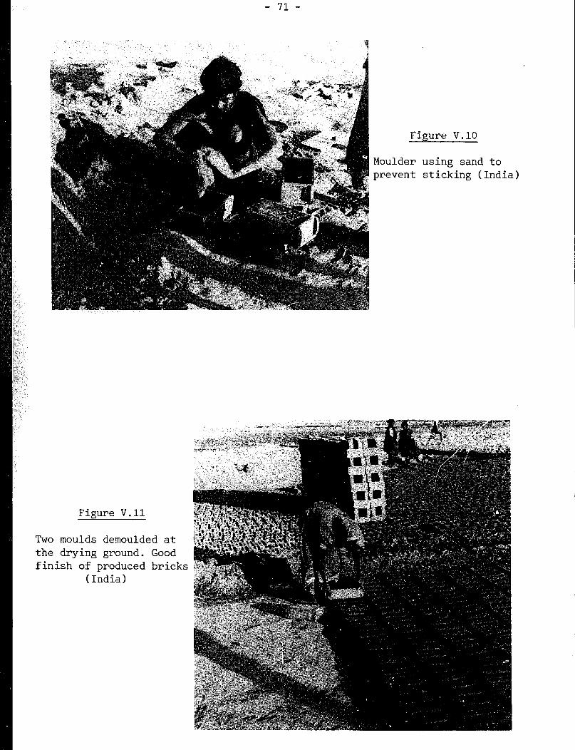
Figure V.10
Moulder using sand to prevent sticking (India)
Figure V.ll
Two moulds demouldf the drying ground.
finish of produced (India)
?d at
Good bricks

- 72 -
Attempts are often made to utilise the moulder's skills to the full, by
having clotlnakers prepare suitably sized pieces of clay ready for throwing
into the mould. Elongated balls are prepared at a works in Ghana (figure
V.12) and used in multi-cavity moulds in an attempt to increase productivity
(figure V.13). In this works sawdust is used instead of sand to assist
demoulding since it is readily available. The bricks are demoulded at the
bench, on to a wooden pallet, then carried to the drying area five at a time.
Sand-moulding continues as a commercial method of production of hand-made
bricks in the United Kingdom to satisfy a particular market requirement for
bricks with variable texture and appearance. The moulders work at a bench
with single cavity wood moulds. Instead of sanding the mould, the clot is
covered in sand. Details of this method are illustrated in figure V.14.
Given the stiffness of the mix, excess clay cannot be removed from the top of
the mould by pushing with hands or a striker. Instead, a bow cutter, which
consists of a taut wire on a bent stick or wooden frame, is used for this
purpose.
Given the advantage of using stiffer clays, the Intermediate Technology
Workshop (ITW) in the United Kingdom has developed a hinged bottom mould.
Instead of having air inlet slits at the base, the air could be admitted by
lifting the base from one end. This device has been successfuly used in
commercial production in several countries in Africa (figure V.151, producing
well-formed bricks.
Recently, the United Kingdom Building Research Establishment has
commissioned the Intermediate Technology Workshop to develop hand-moulding
processes to improve slop-moulding without the use of sand, since the latter
is not available in all locations. One improvement proposed by ITW is the use
of dry clay ground up finely to dust. The latter may then be used to preveL:t
the clot from sticking in the mould, provided it remains in the mould for a
few seconds. Quick demoulding is necessary as the dampness of the clot makes
the dust sticky, and demoulding difficult.
I'I'W has developed two improved moulding devices which are described in a
published document (41). A summary description of these two devices is
provided below.

Figure V.12 Figure V.13
Hinged-bottom mould and moulded
brick (Southern Sudan)
Figure V.14
Moulder throws preformed clot. Use of
five cavities mould (Ghana)
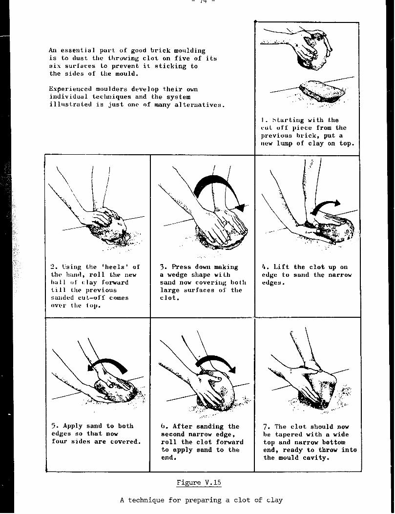
An essential part of good brick q oulding is to dust the throwing clot on five of its six surfaces to prevent it sticking to the sides of the mould.
Experienced moulders develop their own individual techniques and the system illustrated is just one of many alternatives.
2. Using the ‘heels’ of thl* roll new
of forward 11 previous
cu comes OVC'I 1 IIt! iOlJ.
5. Apply sand to both edges so that now four sides are covered.
.:;
3. Press down making a wedge shape wi Lh sand now covering bo t Ir large surfaces oi’ the clot.
(J. After sanding the second narrow edge, roll the clot forward to apply sand to the end.
I . Starting with the CUL off piece from the previous brick, put a new lump of clay on top,
4. Lift the clot up on edge to sand the narrow edges.
7. The clot should now be tapered with a wide top and narrow bottom end, ready to throw in1 the mould cavity.
Figure V.15
A technique for preparing a clot of day
- 75 -
(i) The turnover mould
The turnover mould is another moulding device which may be easily produced
locally. It is a four-sided wooden mould with a sheet steel lining turned in
for 3 mm at the bottom to hold the clay in the mould. After the sanded clot
is thrown and excess cut off, the four mould sides are lifted, freeing the
moulded brick from the fixed base and its frog plate. The sides pivot on a
simple bearing, and after a 180' rotation, a sharp knock on an end stop
causes the moulded brick to drop out on to a pallet (which can be rotated with
the mould). Figure V.16 illustrates the device and its operation.
(ii) The table mould
The local production of a second moulding device, the table mould,
requires the skill of a carpenter or metalworker for the manufacture of some
parts in order to ensure long reliable performance. Figure V.17 shows the
mould recessed into the table. Once the sanded clot has been thrown and
excess cut off with the built-in cutter, the brick may be ejected by raising
the mould bottom by use of the foot-operated lever (figure V.18). Stiff
bricks of excellent shape and clean arrises may be produced with this moulding
device. It is advisable tc transport them on light-weight hand-held wooden
pallets in order to avoid finger-marking the smooth surface. The bricks are
normally stiff enough to be stood on edge. Depending upon local skills and
materials availability, the main structure of the table mould may be
fabricated from box-section steel (figure V.18), steel angle and timber
(figure V.171, or timber only (figure V.19). The mould should be lined with
sheet steel and a frog plate may be fixed to the base. The cutter can either
be built in or a separate bow cutter can be used instead. The sequence of
moulding is illustrated in figure V.19.
Advice or supply of parts for this moulding device may be sought through
the developers of the system, ITW. This moulding device has been used in
several African countries, Sri Lanka and the Caribbean. A new feature which
is being incorporated in the device consists of a lid which can be locked down
on top of the mould, allowing the base to be raised slightly through a
hand-operated lever and cam. This device allows some additional compaction
of the clay, further improving the quality of the brick. However, it slows
down production.
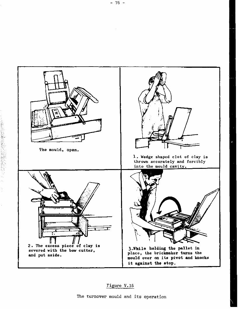
- 76 -
The mould, open,
1. Wedge shaped clot of clay is
and put aside.
3.While holding the pallet in place, the brickmaker turns the mould over on its pivot and knocks
it against the atop.
Figure V.16
The turnover mould and its operation

- 77 -
Robust Sliding bow cutter Special brick- timber with built in tensioner ejecting mould frame box I \ /
Figure V.17
The table mould
Figure V.18
Table mould; pedal being depressed to eject brick. Each brick is handled with pallets and stacked on racks
(United Kingdom)

- 78 -
ay ie cut off with
is pressed down to ejec e oi’f-cot ie removed and set the brick.
Firzure V.19
Operation of the table mould
- 79 -
III. TRANSPCRTATION OF BRICKS TO DRYING AREAS
Slop-moulding requires that bricks be carried in the mould to the drying
area and set bed face down.
Where floors are fairly flat and hard, the labour needed to carry
sandmoulded bricks, which are generally demoulded before transport, can be
minimised by using barrows. ITW has developed racks for the transport of
green bricks. Adapted hack barrows with forks are also available for the
transport of 20 bricks at a time (figure V.18).
Sand-moulded bricks cannot be stacked on top of each other when first
demoulded. Specially designed, large flat-top wheelbarrows may be used to
carry 20 to 30 bricks at a time to the drying area. These bricks can be set
on edge to dry rather than on the bed face. To minimise the load on the
hands, the wheel of the barrow should be set well back under the load. Figure
V.20 illustrates one hack barrow used through many years in the United
Kingdom. Damage to bricks can be minimised if the wheel is sprung.
IV. SKILL REQUIREMENTS AND TRAINING
Mechanised brick-moulding requires a knowledge of clay characteristics as
well as an in-depth understanding of mechanics and electricity. The
mould-operators should also be able to undertake routine preventive
maintenance and inspection for wear and tear of the equipment. They should
also demonstrate an organisational ability in order to avoid loss of
production through machine-servicing and repair. In practice, the machines
will need constant adjustment during the working day.
Equipment used in hand-moulding should be strongly and accurately made,
and kept clean. Hand-moulding skills require an appreciation of the nature of
the clay and experience in throwing. In particular, the operator should be
fully aware of the various remedial measures needed for the preparation of a
mix with the right characteristics. He should also know how to throw with
sufficient force and confidence so that the clot does not strike the side of
the mould. Otherwise, a sanded clot would lose its sand and stick in the
mould.

- 80 -

- 81 -
In general, skills are passed on within families. In addition,the
techniques can be learnt elsewhere within a relatively short period of time.
This is particularly the case for sand-moulding. There are a few 'tricks of
the trade', which may help the beginner. Firstly, there is no substitute for
a good hard accurate throw if the operator is to avoid the time-consuming
pushing of clay into unfilled areas and the production of defective bricks.
It'is preferable to discard a poorly-moulded brick and send it back to the
preparation stage than to go through subsequent stages and end up with bricks
which cannot be marketed. Secondly, whenever sand-moulding is used with stiff
clays, a hard bump of the mould on the bench helps to consolidate the clay and
frees it from the mould. While the bumping and demoulding may be the most
difficult skill to learn, such skill is not needed when the table mould is
used. Thirdly, although the sand is the basic material preventing the clay
from sticking, it is useful to wipe the surface of the mould occasionally with
a rag soaked with oil in order to improve demoulding. The oil consumption is
very small, and no special type of oil is needed. If none is available, a
rag wetted with water may also be helpful. Little training is required for
the sandlooulding process. For example, the well-formed and accurately-shaped
brick in figure V-21 was moulded in a bottophinged mould by an inexperienced
research scientist after only a few preliminary trials. The table mould seems
eminently suitable when accurately-formed stiff bricks are required, where few
skills exist and when little capital is available.
Figure V.21
Brick moulded in hinged-bottom mould
by non-craftsman
(United Kingdom)

- 82 -
V. I!RODUCTIVITY OF LAJ3OUR
It is not easy to measure or compare production rates as tasks are often
shared. For example, clots may be made by the moulder himself or by a
helper. Some moulders carry bricks to the drying area, while others have
runners to perform the task. In mechanical production, it is difficult to
assign a particular number of people to the shaping machine, since a man may
be tending or servicing a variety of machines.
Table V.1 compares a number of mechanised and manual methods for the whole
brickmaking process and for moulding only. Some of the estimates may include
clay preparation, clot forming and carrying, while others may not.
Table V.l
Labour productivity in moulding
(man/hours per 1,000 bricks)
Area Brick factory (complete process) Area Moulding only
hand-made bricks -
Extruded wire Handmade
cut bricks bricks
West Africa 37 97 East Africa 20
India 45 60 Madagascar 8
United Kingdom (traditional) 21
United Kingdom (table mould) 13
Source: 26, 33, 39, 41, 42.
Each country seems to have its own preferred method for hand-moulding:
squatting and moulding on the ground in India, standing in Sudan, etc. In
Madagascar, the moulder stands and works with his mould sloping away, fixed on
top of a stout post. In the United Kingdom, a moulding bench is preferred.
These methods are illustrated in some of the pictures within this chapter.
These pictures also show that moulds may have one to five cavities. A simple
cavity requires more running to the drying area for slop-moulding. On the
other hand, five cavity moulds are very heavy when full. Changes to accepted
methods of moulding would probably result in at least a temporary reduction in
output. Where possible, however, it is recommended that the moulder stands
rather than squats, uses the sand-moulding method and works on a table or
bench.
- 83 -
A study of the brick industry in Colombia(43) concludes that direct
evidence on the relative productivity of various technology levels is
inadequate. However, indirect evidence indicates that it is worth while
setting up labour-intensive units. The analysis carried out on the brick
industry suggests that technologies imported from industrialised countries may
not always be feasible.
JIand-moulding can produce bricks of technically good quality, at minimum
capital cost. This labour-intensive method is highly suited to the varying
c market demand likely to be found in many developing countries. Some simple
devices can lighten the burden and improve the working conditions of the brick
moulders.
CHAPTER VI
DRYING
I. OBJECTIVES OF DRYING
There are several reasons for the drying of bricks before firing. These
are briefly described below.
- In order to obtain the high strength and water-resistant properties of
ceramic materials, the bricks must be burnt in a kiln to a high
temperature. The bricks are piled up one on top of another,
approximately 20 bricks high. Thus, the bricks at the bottom must be
strong enough to carry the weight of those above. When first demoulded
after shaping, the green brick may not be able to bear the weight of
even one more brick without showing some distortion. When a certain
amount of moisture has dried out, and the brick clay is approximately at
the critical moisture content (see Chapter II), the bricks become
"leather-hard". They are then sufficiently rigid and strong for
handling and stacking.
- Once the "leather-hard" condition is reached, the
preferable that this shrinkage takes place before
for burning, lest the shrinkage causes the whole
become unstable, or to collapse within the kiln;
bricks shrink. It is
bricks are piled high
setting of bricks to
- Even after the "leather-hard" condition has been reached, there is much
more water to be dried out of the bricks. If this is not done, the
water in the bricks nearest to the heat source will evaporate and
condense on cold bricks away from the heat source. These bricks will
then absorb the water and get spoilt.
- 86 -
- Another risk is that water remaining in green bricks lnay turn to steam
if the heat rises too quickly. This steam will buiLd up pressure within
the bricks, causing them to rupture. To minimise the risk, bricks
should be as dry as possible before being put into the kiln;
- Within the kiln, any water remaining in the green bricks will only be
driven out by burning expensive fuel. Fuel costs may thus be reduced if
the maximum of water is removed through natural drying.
\
II. ARTIFICIAL DRYING
Drying should be completed with a minimum loss of bricks, and a minimum
cracking and deformation of the latter (see Chapter II). The rate at which
moisture evaporates from the surface should not be greater than the rate at
which it can diffuse through the fine pores of the green brick. Thus, there
is no purpose in creating more draught over the surface, or in heating the
outside surface over a certain temperature. In fact, such action will cause a
faster shrinkage of the surface than that of the interior of the brick, and
thus cracking of the latter.
If drying is too slow, an opening material should be specified for the
mix, or the brick should be reduced. A reduction in the volume of the brick
may be achieved through the production of frogged or perf&>rated bricks. The
reduction of depth cannot, however, be carried too far if bricks were to be of
a minimum strength. Once bricks are leather-hard, the drying rate can be
increased.
If moisture diffuses to the surface, evaporates, but then remains just
above the surface of the brick as a stagnant layer of moist air, further
evaporation will be depressed. This will happen even when bricks are heated
in a dryer. In this case, the drying process should be modified in order to
avoid the above problem.
The rate of drying depends on diffusion rate of moisture in brick,
temperature, humidity and air speed. In temperate c'limates, where drying is
not possible during the cold damp winter months, medium brick plants use
floors heated by fires. This raises the air temperature and reduces the
relative humidity, thus enabling drying to take place. This drying is costly
as it requires large amounts of fuel. Other systems include chamber dryers
for batches of bricks and tunnel dryers which operate continuously.

- 87 -
In the operation of artificial dryers, energy is required to supply the
latent heat of evaporation of the water as well as to heat the bricks and the
air passing through the dryer. It is also required for other heat losses
into the surrocndings.
Estimates of total energy requirements for evaporating one kilogram of
water are provided in Table VI.1 below:
Table VI.1
Energy requirements for drying bricks
Energy (kJ per kg water evaporated)
Efficiency of
process Hot floor dryer Chamber dryer Tunnel dryer
High 7 100 3 300 3 300
Low 12 400 8 900 7 100
Source: 45
Calculated energy requirements for the drying of bricks range from 3,000 to
8,000 MJ per 1,GOO bricks. These energy requirements are relatively important
when compared to those yeeded for the firing of bricks (i.e. 5,000 to 16,000
MJ per 1,000 bricks(8, 10)). Hence, it should be realised that energy for
artificial drying is of similar magnitude to that required for firing.
Artificial drying is mostly needed in the automated large-scale works,
where automatic handling of bricks might be justified economically, and where
kiln designs may be such that waste heat can be conducted from kilns to
dryers. The tunnel kiln lends itself to recovery of heat from the cooling
zone, but in less sophisticated and smaller kilns it is difficult and
relatively expensive to collect the heat for drying. One cheap alternative
could be to dry bricks by placing them around the kiln. This alternative may
not be feasible if space is not sufficient for drying all the bricks, and if
it were to restrict access to the kiln.
A recent drying method involves the use of rotating air dryers. In these
dryers, hot air is applied as occasional blasts along strategically positioned
- 88 -
racks full of bricks, the draught removing the accumulated layer of moist air
which has collected close to the brick surface.
In some tropical countries, drying is difficult during the wet season.
Consequently , large plants are often equipped with air dryers. Figure VI. 1
shows rotary dryers awaiting installation in a Ghanaian brickwork.
Bricks can be weighed from time to time to estimate the amount of water
which has dried out. These estimates may then be used to determine the time
needed for bricks to reach the “leather-hard” stage.
In view of the high cost and/or the scarcity of fuel, the hot weather
conditions in a large number of countries, overall production considerations
and market requirement 9, the use
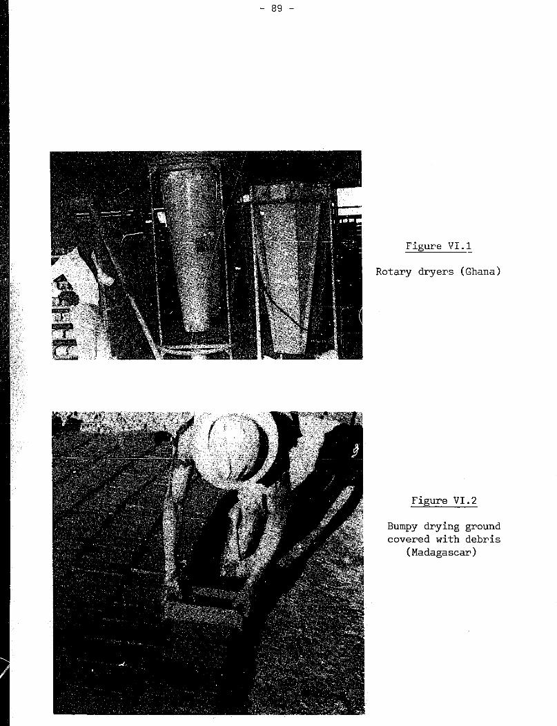
- 89 -
Figure VI.1 -
Rotary dryers (Ghan .a)
Figure VI.2
Bumpy drying grou
covered with debr
(Madagascar)
nd
Iis

Figl!re VI.3
'&rmtly dried brick distorted and
hovered with debris (West !Sciani
Figure VI.4
Good bricks dried on clean, level ground
(West Sudan)
- 91 -
Sand-moulded bricks, being more firm than slop-moulded bricks, are nut
likely to pick up debris or to distort easily. They may also be set down on
edge, which further reduces the chance of distortion due to uneven support.
As soon as bricks are dry enough to handle (i.e. once they have reached
the leather-hard stage), they should be turned right over to allow the face
which was in contact with the ground to dry. The required drying time will
vary with weather conditions, but should not generally exceed one or two days.
After approximately three more days, depending upon weather conditions,
the bricks can be removed from the drying ground and built into long open work
walls eight or ten bricks high. These walls are known as hacks (figure
VI.5). The drying .of bricks should continue for a few weeks more. Bricks
become lighter in colour as they dry. Sample bricks should be broken in order .
to check whether the inside is of light colour and therefore dry.
The bottom bricks in the hack may remain wet if laid directly on the
ground. It is therefore advisable to build the hacks on already burnt bricks
or wooden planks, which may be left in position permanently.
Although light rain may not harm exposed green bricks, heavy rain can have
serious consequences, and days of hard work may be wasted in a few minutes.
Figure VI.6 shows bricks damaged by rain and bricks which are -laid out for
drying after the rain storms. Where the risk of heavy rains exists it is
almost impossible to carry all the bricks under cover, especially newly-made
slop-moulded ones. Instead, one may need to use plastic sheeting for
protection against the rain, Plastic sheeting may not, however, give the best
protection as it is difficult to lay the plastic over a large amount of bricks
unless the stacks of bricks are separated by walkways. Furthermore, the
plasti., sheets must be weighted down to prevent the wind from blowing them
away. Since bricks close to the edges of the plastic sheets may not be
protected effectively, it is advisable to use special cover or permanent sheds
whenever drying takes place during uncertain weather conditions.
One of the chief reasons for the cracking and distortion of bricks during
the drying stage is the high rate of drying. This rate is difficult to
control in the open air, although the use of leaves or grass on top of the
bricks may help control drying to some extent. A high rate of drying may
result from the action of the sun as well as from low humidity levels and
winds. Thus, it may take place even when the bricks are shaded.

-..- .-
Figure VI.6

,-*m
- 93 -
Hack drying is an effective drying method used in the temperate climate of
the United Kingdom over many years. In this method, bricks are transported
bed face down on the hack barrow and set on edge on wooden planks in two long
parallei rows. Hack covers, made from pairs of thin sheets of wood tied with
a cross bar long enough to span both rows of bricks, are laid carefully on the
green bricks for protection against rain. By the time the end of the row is
reached, a second course of green bricks may be laid without distorting those
in the first row. A maximum of six courses of bricks may be built in this
ma;sner. Such a hack ground is illustrated in figure VI.7. The boards are
kept at. the correct separation by an occasional batten fastened between them.
Only the tie-bars of the covers rest on the bricks. Thus, the sloping covers
do not damage the -upper corners of the bricks. Th2sc covers are si;fficier;t tc
protect bricks from the heavy vertically falling rain. In rainy and windy
weather an extra board or sacking may be placed on the side facing the wind.
Rainwater from the edge of the roof falls into a gulley on either side of the
hack. The earth dug from the gulley is spread between gullies in order to
raise the plank slightly. The preferred direction of the hacks should be such
that the sun shines on either side of the wall for equal periods of time.
Figure VI.8 shows bricks close-set in a covered hack. When they are dry
enough to handle, they can be reset with wider spacings, the hacks then
becoming slightly higher. Wider spacing increases the drying rate, which may
be necessary after the leather-hard stage has been reached. Hacks must be
sufficiently apart to allow access and operation. The drying of bricks with
this method takes several weeks. An area for the hack ground of approximately
one-tenth of a hectare should be allocated for an output of 1,000 bricks per
day(8). This drying method may be adopted in showery weather or during short
periods of rain in many countries.
III.2 DryinK in a shed
Provision of a shed, sufficiently large to cover both the moulding and
drying areas and, possibly, the kiln, may be considered in some cases. Such a
shed may, however, constitute the largest item of capital expenditure in
setting up a small brickworks. A shed covering only the drying grounds will
be cheaper and will improve the chances of successful drying. Figure VI.9
shows a simple structure used in Madagascar. This shed may be used
efficiently if bricks can be built up in hacks when firm enough.

Figure VI.7
Transferring freshly moulaed bricks from barrow to dry in hacks with moveable covers
Figure VI.8
Covered drying hack

- 95 -
The use of racks reduces the volume needed for the drying of a given
number of bricks (see figure VI. 10). Such racks enable soft, freshly moulded
bricks to dry one brick high on each shelf. Thus, they will not be distorted
by other bricks above them. Some cracking may take place in bricks nearest
the outside of the shed, where direct sun, low humidity and great air movement
cause faster drying. Side screens are necessary under such circumstances.
Bricks should be turned on to their sides once they have reached the
leather-hard stage after a few days of drying (28).
Side screens allow a better control of the drying procedure. They may be
made out of plastic, cloth, wood, metal, woven grass or bamboo, The most
convenient side screens should be of a type which can be rolled up easily when
not required. When down, they keep off driving rain and direct sunshine,
increase and equalise humidity within the shed, and prevent excessive air
circulation through the stacks of bricks. Access to the shed should be from
the side sheltered from the wind. When drying is too slow, screens can be
raised.
A cheaply constructed but effective drying shed is shown in figure VI.ll.
Pole timbers support a roof, high enough to allow workers to operate within
the shed. Rudimentary but effective side screens are available for rapid
use. Racks for holding the green blocks consist of planks, supported at the
ends on previously-f ired bricks, thus avoiding the necessity for substantial
wooden posts to bear the weight of the loaded shelves. For safety reasons,
these racks must not wobble or tilt.
IV. SHRINKAGE
Shrinkage is inevitable on drying clayware such as bricks. The most
important rule ia to dry bricks as slowly as possible in order to minimise
stresses and the incidence of cracking and distortion. A 7 per cent linear
shrinkage should not cause difficulties in subsequent processing. A 10 per
cent linear shrinkage may also be acceptable with some clays if drying is
carried out carefully.
Problems may be lessened if the clay proportion in the mix is reduced by
the addition of sand or grog.
Fully shrunk bricks are not completely dry. Further drying is needed
before they are ready for firing in the kiln.
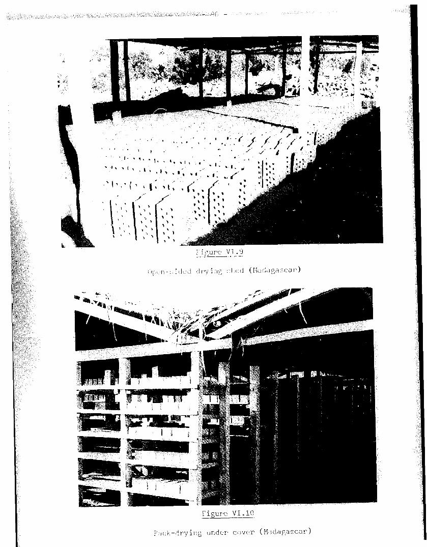
- !jb -

- 97 -
Figure VI.11
Rack-drying under cover, with removeable
side screens (Madagascar)

CHAPTER VII
I. OBJECTIVEg OF FIRING
The firing of green bricks changes their physical s,:ucture and gives them
good mechanical properties and resistance to slaking by water, If carried out
properly, the firing process should minimise the occurrence of the following
problems:
the splitting of bricks due to the incomplete removal of moisture before
firing;
Low strength bricks due to insufficiently hard firing;
Slaking by water, due to inadequate control of the firing temperature;
Bricks fused together, melted on one face, or distorted by the load
imposed by other bricks on top; these problems are caused by too high a
temperature;
Variety of sizes of fired bricks although
same size; this is caused by temperature
parts of the kiln;
the green bricks were of the
variations between different
Fine cracking over brick surfaces resulting from a
change, either during heating or cooling, or from
vapour from heated bricks on to cooler bricks(47);
Local cracking over hard lumps or stones mixed
inclusions should have been removed during clay
too rapid temperature
condensation of water
in the clay. These
preparation, although
rapid changes of temperature may have aggravated the problem;

- 100 -
- Black cores in bricks: these are not necessarily detrimental if they
are due to the presence of carbon although the latter ought to have been
burnt up as a contributory fuel in the interest of cost reduction (48).
Black cores may also be due to iron in the reduced, low valency ferrous
form. Both causes may be remedied by providing sufficient oxygen (e.g.
by leaving adequate paths for the flow of air between the bricks and
through the kiln(47) 1. An opening material may also need to be mixed in
the body;
- Bloating: cracked blisters appear on the surface of the bricks as a
result of the pressure of gases produced after vitrification has
commenced; holding the temperature steady at an earlier stage could
allow the gases to diffuse out while the body is still permeable. The
problem may also be alleviated by incorporating an opening material in
the clay;
- Limebursting; this problem may be solved by removal or grinding of
pieces of limestone, or in some cases, by adding salt(49).
Alternatively, the quicklime formed within the brick may be dead burnt
by heating to approximately l,lOOcC (SO);
- Ef florescence and sulphate attack of cement-based mortars and
renderings; this problem may be reduced by harder firing, as an
alternative to other methods and precautions (see Chapter IV);
- Scum on brick surfaces may be minimised by preventing condensation of
products of combustion on cold, green bricks.
11. TECHNIQUES OF FIRING
Whatever system of firing is used, it is recommended that a low heat be
first applied to the green bricks in order to drive off any residual
moisture. This should continue until no more steam is evolved. This part of
the heating is known as water-smoking. The completion of this firing stage
may be simply tested by inserting a cold iron bar into a space purposely left
between the bricks in the kiln, and by withdrawing it after only a few
seconds. Condensation on the bar indicates that steam is still being evolved,
and low heat should be continued until no condensation is found on the cold
bar after re-insertion. This could’ take a whole week in some cases and needs
plenty of air through the kiln.
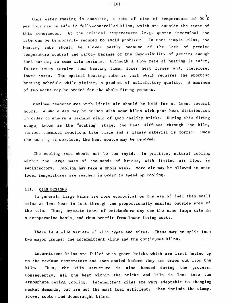
- 101 -
Once water-smoking is complete, a rate of rise of temperature of 5o”c
per hour may be safe in fullyacontrolled kilns, which are outside the scope of
this memorandum. At the critical temperatures (e.g. quartz inversion) the
rate can be temporarily reduced to avoid problem::.. In more simple kilns, the
heating rate should be slower partly becatise o: the lack of precise
temperature control and partly because of the impcssibilitv of getting enough
fuel burning in some kiln designs. Although a sl<~ ratz af heating is safer,
faster rates involve less heating time, lower heat losses and, therefore,
lower costs. The optimal heating rate is that w+!lch requires the shortest
heating schedule while yielding a product of satisfactory quality. A maximum
of two weeks may be needed for the whole firing process.
Maximum temperatures with little air should be held for at least several
hours. A whole day may be ne;;led with some kilns with poor heat distribution
in order to ensl*re a maximum yield of good quality bricks. During this firing
stage, known as the “soaking” stage, the heat diffuses through the kiln,
various chemical reactions take place and a glassy material is formed. One e
the soaking is complete, the heat source may be removed.
The cooling rate should not be too rapid. In practice, natural cooling
within the large mass of thousands of bricks, with limited air flow, is
satisfactory. Cooling may take a whole week. More air may be allowed in once
lower temperatures are reached in order to speed up cooling.
III. KILN DESIGNS
In general, large kilns are more economical on the use of fuel than small
kilns as less heat is lost through the proportionally smaller outside area of
the kiln. Thus, separate teams of brickmakers may use the same large kiln on
a co-operative basis, and thus benefit from lower firing costs.
There is a wide variety of kiln types and sizes. These may be split into
two major groups: the intermittent kilns and the continuous kilns.
Intermittent kilns are filled with green bricks which are first heated up
to the maximum temperature and then cooled before they are drawn out from the
kiln. Thus, the kiln structure is also heated during the process.
Consequently, all the heat within the bricks and kiln is lost into the
atmosphere during cooling. Intermittent kilns are very adaptable to changing
market demands, but are not the most fuel efficient. They include the clamp,
sc ove , scotch and downdraught ki Ins.

- 102 -
The continuous kilns have fires alight in some part of them all the time.
Fired bricks are continuously removed and replaced by green bricks in another
part of the kiln which is then heated. Consequently , the rate of output is
approximately constant. The continuous group of kilns includes various
versions of the Hoffmann kiln, including the Bull’s trench, zig-zag and high
draft kilns, and the tunnel kiln. The latter is a capital-intensive,
large-scale continuous kiln, which is outside the scope of this
memorandum. 1
Continuous kilns utilise heat from the cooling bricks to
pre-heat green bricks and combustion air, or to dry bricks before they are put
into tho kiln. Consequently, continuous kilns are economical in the use of
fuel.
III.1 The clamp
The clamp is the most basic type of kiln since no permanent kiln structure
is built. It consists essentially of a pile of green bricks interspersed with
combustible material. Normally, the clay from which the bricks are moulded
also includes fuel material. The clamp kilns were commonly used in the United
Kingdom. Some of these, containing one and a quarter million bricks, are
still used for the production of bricks of various colours and textures.
It is possible to use a variety of burnable waste materials in brick clays
(e.g. sifted rubbish, small particles of coke, coal dust with ashes, breeze).
In countries where timber is produced, large quantities of sawdust may be
mixed with clay before firing. This will reduce the expenditure on th-2 main
fuel for burning the bricks. Waste materials should be of relatively small
size and should not exceed in weight 5 to 10 per cent of the total mixture.
Otherwise, the clay will become difficult to mould or the’ finished product may
become too weak or too porous. Furthermore, the added fuel material should be
thoroughly mixed with the clay.
A flat, dry area of land is first chosen, and a checkerwork pattern of
spaced out, already burnt bricks laid down over an area of approximately 15 m
by 12 m. Fuel in the form of coke, breeze or sm.all coal2 is then spread
between the checkerwork bricks, covering the latter with a layer at least 20
cm thick. Dry, green bricks are next closed-laid on edge upon this fuel bed.
’ In the tunnel kiln, bricks stacked on heat-resistant trolleys or cars are subjected to increasingly hotter temperatures, then cool off before leaving
ihe lIunnel- Coke or breeze is generally used in clamp kilns in the United Kingdom. Small coal is used in a number of developing countries, such as Zambia (51).
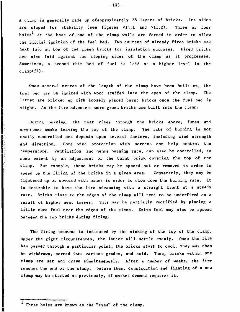
- 103 -
A clamp is generally made up ofapproximately 28 layers of bricks. Its sides
are sloped for stability (see figures VII.1 and VII.2). Three or four
holes’ at the base of one of the clamp walls are formed in order to allow
the initial ignition of the fuel bed. Two courses of already fired bricks are
next laid on top of the green bricks for insulation purposes. Fired bricks
are also laid against the sloping sides of the clamp as it progresses.
Sometimes, a second thin bed of fuel is laid at a higher level in the
clamp( 51).
Once several metres of the length of the clamp have been built up, the
fuel bed may be ignited with wood stuffed into the eyes of the clamp. The
latter are bricked up with loosely placed burnt bricks once the fuel bed is
alight. As the fire advances, more green bricks are built into the clamp.
During burning, the heat rises through the bricks above, fumes and
sometimes smoke leaving the top of the clamp. The rate of burning is not
easily controlled and depends upon several factors, including wind strength
and direction. Some wind protection with screens can help control the
temperature. Ventilation, and hence burning rate, can also be controlled, to
some extent by an adjustment of the burnt brick covering the top of the
clamp. For example, these bricks may be spaced out or removed in order to
speed up the firing of the bricks in a given area. Conversely, they may be
tightened up or covered with ashes in order to slow down the burning rate. It
is desirable to have the fire advancing with a straight front at a steady
rate. Bricks close to the edges of the clamp will tend to be underf ired as a
result of higher heat losses. This may be partially rectified by placing a
little more fuel near the edges of the clamp. Extra fuel may also be spread
between the top bricks during firing.
The firing process is indicated by the sinking of the top of the clamp.
Under the right circumstances, the latter will settle evenly. Once the fire
has passed through a particular point, the bricks start to cool. They may then
be withdrawn, sorted into various grades, and sold. Thus, bricks within one
clamp are set and drawn simultaneously. After a number of weeks, the fire
reaches the end of the clamp. Before then, construction and lighting of a new
clamp may be started as previously, if market demand requires it.
1 These holes are known as the “eyes” of the clamp.

Figure VII.1
Clamp kiln - schematic drawing
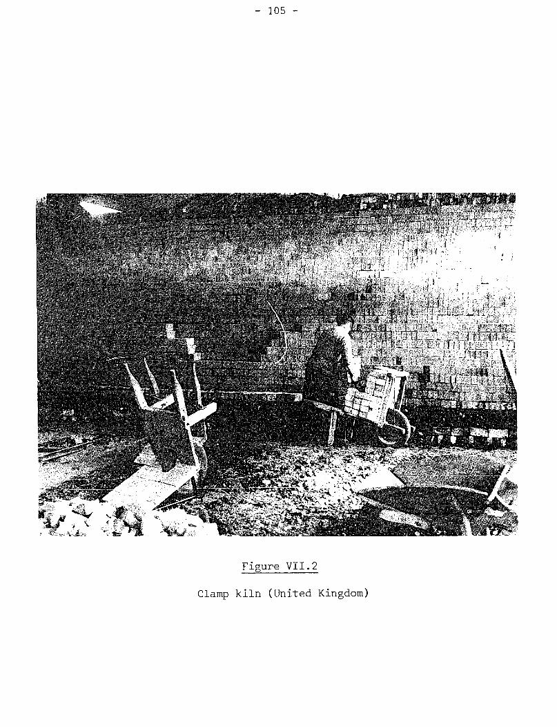
- 105 -
Figure VII.2
Clamp kiln (United Kingdom)

- 106 -
If enough air flows through the bricks during firing, the oxidising
process will give them a red colour. Where air is scarce, reducing conditions
due to the gases from the burnt fuel will yield orange or yellow bricks,
especially if a limy clay is used for moulding. Variations in colours will be
normal even on a single brick face.
As the fuel is in close contact with the green bricks, the fuel efficiency
of a large clamp of 100,000 to 1 million bricks can be fairly high (e.g. about
7,000 MJ per 1,000 bricks). Smaller clamps will be less efficient, as a
result of the greater proportion of outer cooling area for a given volume.
However, they may be operated successfully with only 10,000 bricks. For low
production rates, it is only necessary to fire a clamp occasionally and have
the bricks in place until they are sold,
The bricks near the centre of the clamp will be the hardest. Others
should be sufficiently good for many uses. They should be sorted for sale as
best, “seconds” and soft-burnt bricks. However, 20 per cent of the bricks may
still not be saleable. Fortunately, many of these rejects can be put into the
next clamp for refiring, or used in the clamp base, sides or top.
III.2 The stove kiln
A widely used adaptation of the clamp is the stove kiln, also mistakenly
called a clamp. If-the fuel available is of a type which cannot be spread as
a thin bed at the base of the kiln and/or is not in sufficient quantity to
burn all the bricks without the need for replenishment, tunnels can be built
through the base of the pile in order to feed additional fuel (figure VII.3).
This is a suitable method of burning wood, the latter being one of the most
frequently used fuels for small-scale brickmaking in developing countries.
Usually, the outer surface of the piled-up bricks is scoved, that is to say
plastered all over its sides, with mud (figure VII.4). Thus, the name of the
stove kiln.
The construction cf a stove requires a level, dry area of land.
Previously fired bricks, if available, lay bed face down to form a good, flat
surface. Three or four layers of bricks are used to form the bottom of the
tunnels. The width of each tunnel is approximately equal to that of two brick
lengths. Three lengths of bricks separate the tunnels. Alternate courses are
laid at right angles to each other (i.e. a course of headers, followed by a
course of stretchers). Two short tunnels (e.g. approximately 2 m long) may be
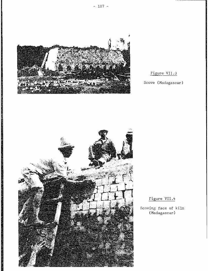
- 107 -
Figure VII.3
Stove (Madagascar)
Figure VII.4
Scoving face of kiln (Madagascar)
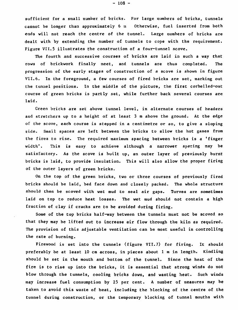
- 108 -
sufficient for a small number of bricks. For large numbers of bricks, tunnels
cannot be longer than approximately 6 m Otherwise, fuel inserted from both
ends will not reach the centre of the tunnel. Large numbers of bricks are
dealt with by extending the number of tunnels to cope with the requirement.
Figure VII.5 illustrates the construction of a four-tunnel stove.
The fourth and successive courses of bricks are laid in such a way that
rows of brickwork finally meet, and tunnels are thus completed. The
progression of the early stages of construction of a stove is shown in figure
VII.6. In the foreground, a few courses of fired bricks are set, marking out
the tunnel positions. In the middle of the picture, the first corbelled-out
course of green bricks is partly set) while further back several courses are
laid.
Green bricks are set above tunnel level, in alternate courses of headers
and stretchers up to a hei.ght of at least 3 m above the ground. At the edge
of the stove, each course is stepped in a centimetre or so, to give a sloping
side. Small spaces are left between the bricks to allow the hot gases from
the fires to rise. The required maximum spacing between bricks is a ’ finger
width’ . This is easy to achieve although a narrower spacing may be
satisfactory. As the stove is built up, an outer layer of previously burnt
bricks is laid, to provide insulation. This will also allow the proper firing
of the outer layers of green bricks.
On the top of the green bricks, two or three courses of previously fired
bricks should be laid, bed face down and closely packed. The whole structure
should then be scoved with wet mud to seal air gaps. Turves are sometimes
laid on top to reduce heat losses. The wet mud should not contain a high
fraction of clay if cracks are to be avoided during firing.
Some of the top bricks half-way between the tunnels must not be scoved so
that they may be lifted out to increase air flow through the kiln as required.
The provision of this adjustable ventilation can be most useful in controlling
the rate of burning.
Firewood is set into the tunnels (figure VII.71 for firing. It should
preferably be at least 10 cm across, in pieces about 1 m in length. Kindling
should be set in the mouth and bottom of the tunnel. Since the heat of the
fire is to rise up into the bricks, it is essential that strong winds do not
blow through the tunnels, cooling bricks down, and wasting heat. Such winds
may increase fuel consumption by 25 per cent. A number of measures may be
taken to avoid this waste of heat, including the blocking of the centre of the
tunnel during construction, or the temporary blocking of tunnel mouths with

I I I I I I I I I I I I I I I I I I I I
I I I I
I I
I I
I I I I I I I I
I I I
I I I I I I I
I
I
I I I I
. .
I I I I I I I I
I I I I I I I I
i 1 I I I I I I I
1 I I I I I I I I
I I I I I I I I
I I I I I I I I
vent ch;bl, \
Figure VII.5
Stove : schematic drawing

Figure VII.6
Corbelling stove tunnel
(Sudan)
Figure VII.7
Wood in stove tunnel
(Sudan)

- 111 -
bricks. In the latter case, one end may be bricked up and fire set at the
other end. Once the fire is well alight, that end may be bricked up while the
previous one is opened and lighted. Thereafter, the fires may be controlled
by bricking up tunnel mouths with loose bricks and adjusting the vents on
top. As fuel burns away, it must be replenished.
As with all kilns, heat must be gentle at first until all the water in the
bricks is driven off. Adequate air flow is therefore essential to remove the
steam produced. Thus, the vents should be open, and the fires kept low so
long as steam is seen to rise from the top of the stove. This water smoking
period may last several days.
Once the water smoking stage is completed, the fires may be built up
gradually to increase temperatures up to a maximum over a period of a few
days. A maximum temperature is indicated by the charring of dry grass or
paper thrown on top of the stove, or the appearance of a red glow by night.
The vents should be closed with fired bricks well before the maximum
temperature is attained in order to regulate the burning rate and, thus, help
to even out the temperature amongst the bricks. The maintaining of this
temperature for several hours (i.e. soaking stage) requires a last charge of
fuel, the closure of the tunnel mouths and the sealing of closed vents with
mud.
The stove should be left to cool naturally for at least three to four
days. Then if necessary some bricks may be removed from the outside to speed
the later stages of cooling. Subsequently , the bricks may be left in position
until sold. Before collection or despatch, under- and over-fired bricks must
be discarded and the remainder, if of variable quality, should be sorted out
into good quality, ‘seconds’ and soft-fired bricks. Rejects may be
incorporated in the next stove.
Although wood is generally the fuel used in stoves, oil-burners are used
in some countries. Coal, which is also an alternative fuel for stoves,
requires a special grate at each end of the tunnel mouth, and is therefore
more appropriate for firing in permanent kilns.
The fuel efficiency of stoves is low, 16000 MJ of heat being required per
1,000 bricks for a typical African stove ( 10, 52). A square stove has a
smaller cooling area than a rectangular stove, for a given number of bricks.
However, it will require a relatively longer tunnel which may exceed the
allowed length for proper lighting of the stove. Thus, small kilns could be
square while larger ones may need to be rectangular.
In order to increase the heat efficiency, the height of a stove should be
as great as possible, so long as saleable bricks are obtained from the toPa
- 112 -
Safety must be borne in mind, however, as high stoves tend to be unstable as a
result of shrinkage of bricks during firing. Moreover, a high setting
complicates the placing of green bricks on top courses, and increases the risk
of accidents. Figure VII.8 shows a high stove of approximately 60,000 bricks,
after firing and stripping of the outer bricks.
A stove may be built for firing a few thousand bricks only, but will be
less fuel efficient than larger stoves.
III.3 The Scotch kiln
The Scotch kiln is similar to the stove, except that the base, the fire
tunnels and the outer walls are permanently built with bricks set in mortar
(figure VII.9). The kiln itself has no permanent top, green bricks being set
inside the kiln, as shown on the extreme left of figure VII.9. Much basic
construction work is thus saved. A plane and section of a seven-tunnel Scotch
kiln is shown in figure VII.10. Walls on either side are buttressed, and
corners are massively constructed. Access into the kiln is through a doorway
in the end walls. This doorway is filled temporarily with closely laid bricks
(without mortar) during kiln operations. In some kilns the whole end wall is
temporarily erected (40).
Wood is often used for firing the kiln, although oil burners or coal
grates may also be installed. The sink of the bricks - after shrinkage - is
more easily measured than in the clamp or stove kiln, since the fixed position
of the permanent side walls may be used as a reference point. The sink gives
an indication of the firing process within the kiln.
The advantages of the Scotch kiln over other permanent kiln structures are
its simple design and easy erection. Setting and drawing of bricks are also
simple.
The Scotch kilns, like the clamp and stove, are updraught kilns. They
have been widely used in developing countries. Their chief failing is the
irregular heating and consequent large proportion of under- and over-burnt
bricks. This is especially true for clays with a short vitrification range as
they cannot be fired without a good temperature control.
Fuel consumption of the order of 16,000 MJ per 1,000 bricks is generally
the norm for Scotch kilns (8, 42).
III.4 The down-draught kiln
In the down-draught kiln, hot gases from burning fuel are deflected to the
top of the kiln which must have a permanent roof. They then flow down between

Figure VII.8
A high six-tunnel stove (Madagascar)
- ---_ - -._ ‘-
LA-.,.,. *!+ - &,a,
3, :& ~rYy-
-- - ..*- ‘-.i.__i*r-
Figure VII.9
Small Scotch kiln (Madagascar)

- 114 -
/ 63 / ,/’ ,’ ’ a ,,’ I ,/ @!zzl
‘/ ‘/ D /
lz@ , /
lz!J ‘. /”
I --A A-
@izi ------ I llizi@ -------m-
a , .’
@ /
i , ,,’
a , / /
m /
Section at A-A ’ 1m. ’
Figure VII.lC: Scotch kiln - Schematic drawing
- 115 -
the green bricks to warm and fire them. The green bricks rest either upon an
open-work support of previously fired bricks (figure VII. 12) or upon a
per-orated floor through which the warm gases flow. These gases are then
exhausted through a chimney outside the area of the kiln after passage through
a flue linking the kiln floor to the chimney. The warm gases rising through
the height of the chimney provide sufficient draught to pull the hot gases
down continually through the stack of green bricks.
The down-draught kiln is more heat efficient than the up-draught kiln
described earlier. It can be used for various ceramic products (e.g. drainage
pipes and tiles of various types) in addition to the firing of Dricks. The
kiln can be operated at high temperatures and may then be used for the
production of refractory ware.
Circular down-draught kilns may be built in place of rectangular kilns.
They are stronger than the latter, but require reinforcement with steel bands
to keer the brickwork from deteriorating through periodic cooling and
heating. Rectangular down-draught kilns are more simple to build, although
they require also steel t.ie-bars as a reinforcement. They however have the
advantage of being easier to set with green bricks than circular kilns.
Figure VII.11 shows the ground level plan of a rectangular down-draught kiln
of massive construction, with 14 grates for burning fuel. A number of grates
stocked with lighted wood are shown in figure VII.13. The grates may be
prefabricated from iron bars, as indicated in figure VII.ll. A “flash” wall
is built behind the grates to keep the flames off the nearby green bricks.
The wall in the figure is continuous. Alternatively, separate “bag“ walls can
be built around the back of each fire (see figure VII.12 right-hand side).
The continuous wall tends to even out the heating ef fett .
Hot gases rise to the arched crown of the kiln and are drawn down between
open set bricks (figure VII.121 by the chimney “suction”, through the
perforated floor (shown in the figure) along its centre line. There should be
a few small holes at the base of the flash wall, in the underground flue in
order to ensure the burning of bricks near the bottom of the wall. A metal
sheet damper is available near the bottom of the chimney in order to vary the
flow of gases and exercise control over the operation of the kiln. The
control of air flow is achieved by the use of metal doors. These should be
thick enough to avoid distortions (figure VII. 14).
Entrance to the kiln is through small arched doorways (figure VII.15)
referred to as “wickets”. These are bricked up temporarily during firing.
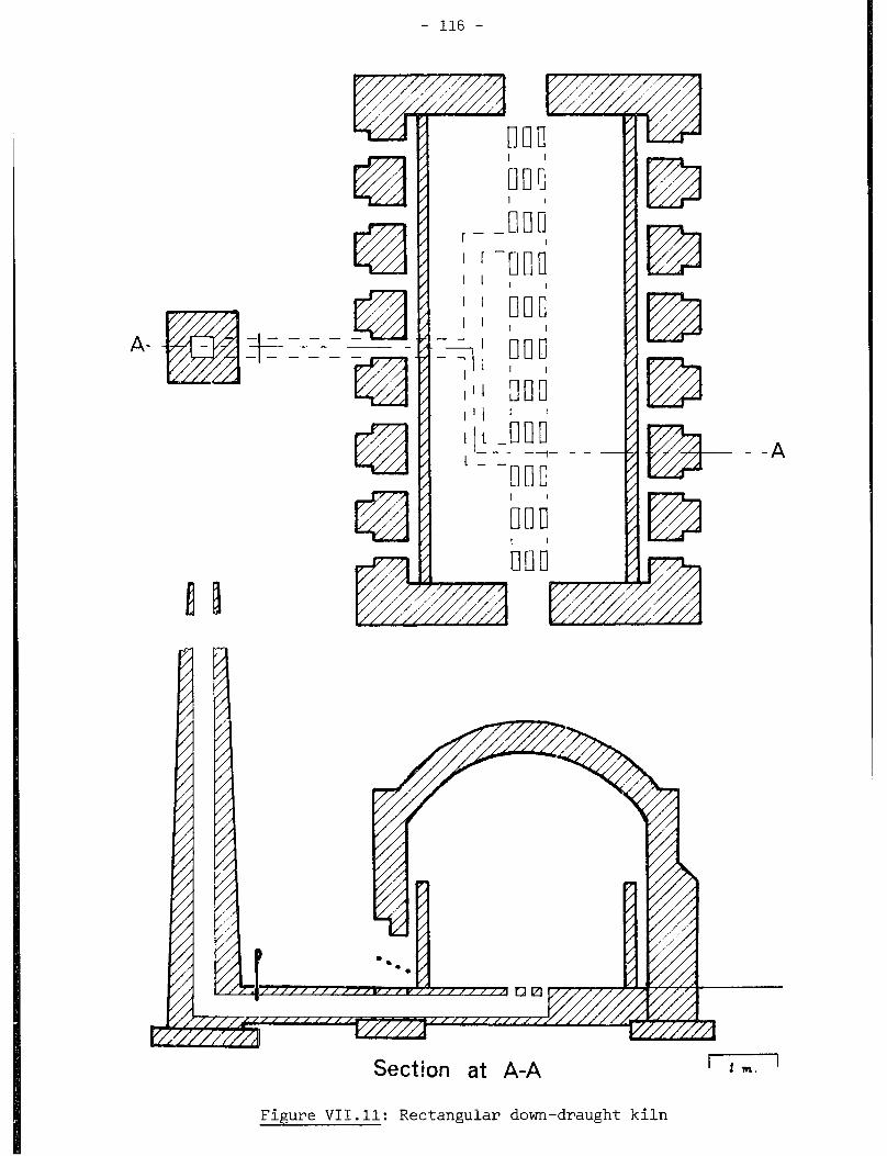
- 116 -
--- - -
--- -- -
1 1 --- - - -
Section at A-A ’ im. ’
Figure VII.ll: Rectangular down-draught kiln
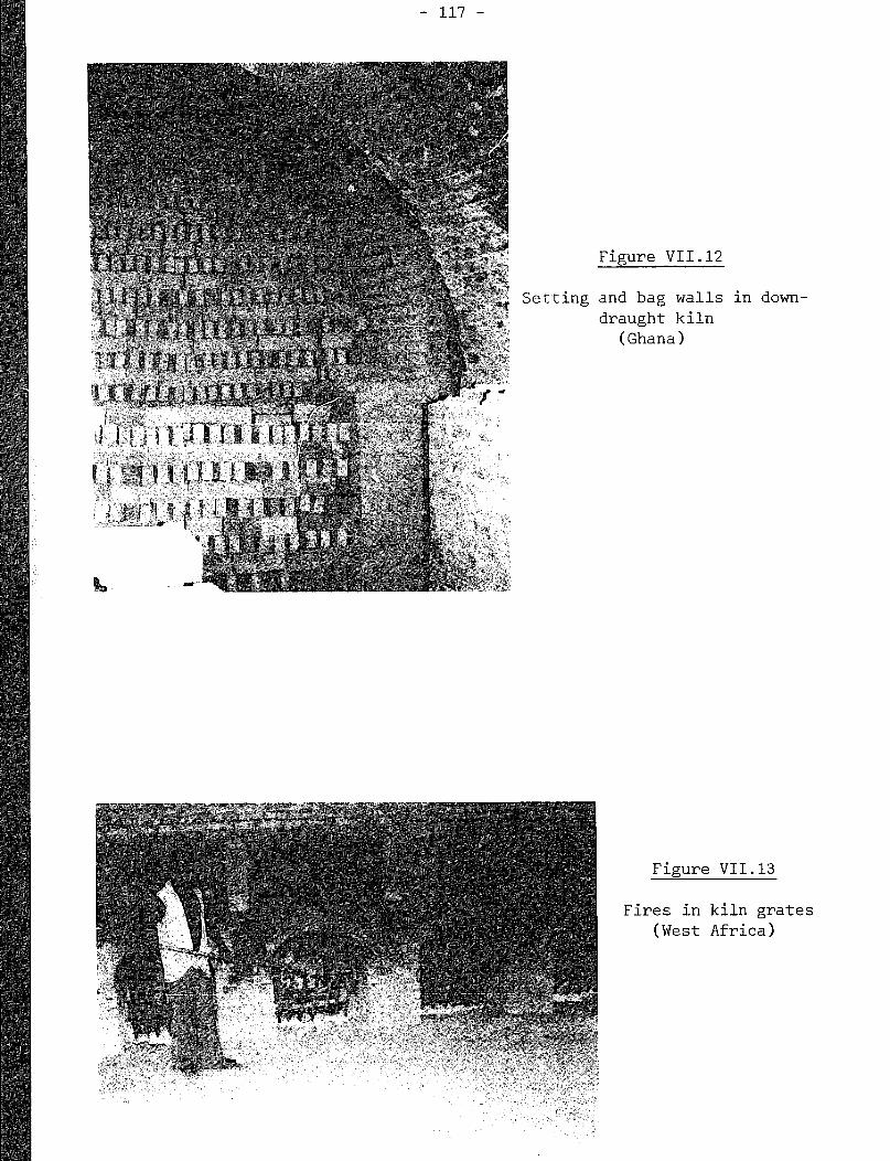
- 117 -
Setting
Figure VII.12
and bag walls
draught kiln (Ghana)
in down-
Figure VII.13
Fires in kiln grates (West Africa)

Metal
- 118 -
Figure VII.14
damper door for kiln
(West Africa)
grate
Figure VII.15
Rectangular down-draught
kiln with covering (Ghana)

- 119 -
The height of downdraught kilns should not be too great, as it is
difficult and time consuming to set bricks at heights that may not be easily
reached by workers.
Down-draught kilns may hold from 10,000 to 100,000 bricks. The one shown
in figure VII.15 takes 40,000 bricks.
Fuel consumption depends greatly upon the condition of the kiln, the
manner of setting the bricks and the control of the firing process. For
example, damp foundations absorb heat, and a badly fitting damper may waste
fuel. The loss of heat varies from one type of kiln to another. Large kilns
consume less fuel than small kilns, for a given number of bricks. An
under-filled kiln loses as much heat as one properly filled. An over-f illed
kiin prevents the passage of hot gases, and this requires a longer burning
cycle. Too much draught allows more heat to be wasted up the chimney. Given
the above varying circumstances, the heat required by downdraught kilns varies
from 12,000 to 19,000 MJ per 1,000 bricks. An exact estimate of heat
consumption requires an in-depth study of the characteristics of the kiln (5,
24, 33).
III. 5 Original circular Hpf fmann kiln
The Hoffmann kiln is a multi-chamber kiln where the air warmed by cooling
bricks in some chambers pre-heats the combustion air for the fire, and exhaust
gases from combustion pre-heat the green bricks. The main advantage of this
kiln is its particularly low fuel consumption rate.
The original Hoffmann kiln was circular (see figure VII.161 and built
around a central chimney. An arched-top tunnel surrounds the chimney at a
distance of a few metres, and is connected to it by 12 flues passing through
the brickwork between the tunnel and the chimney. Each flue can be closed off
by dropping a damper. Entrance into the tunnel is through any one of 12
wickets. During operation most of the kiln’s tunnel is full of bricks either
warming, being fired or cooling.
A typical condition of the kiln is shown in figure VII.16. All but two
neighbouring wickets are closed. Cold fired bricks are drawn from one part of
the tunnel adjacent to one of the open wickets and dry green bricks are set by
the other wicket. Cold air flows to the warm chimney through both wickets.
This air cannot pass through the recently set bricks as they are sealed off

Section at A-A Figure VII.16
Original Hoffmann kiln

- 121 -
with a paper damper across the whole width of the annular tunnel. The air
flows through the bricks which are drawn, into warm bricks further down the
kiln (counter-clockwise in the figure) close to the fire. As the air flows
counter-clockwise, its temperature rises through contact with increasingly hot
bricks. The air is thus pre-heated and ready for efficient combustion in the
firing zone of the kiln where fuel is fed in through closeable holes in the
tunnel roof. Thus, little fuel is consumed for heating the combustion air.
The latter also performs the useful task of cooling bricks for drawing, thus
making kiln space available on a relatively short time. The hot products of
combustion cannot be vented straight to the chimney through the nearest flue,
as the latter is closed (this is indicated by a dot in the circle centre in
the figure). Instead, the hot gases pre-heat unburnt bricks. Thus, less fuel
is required at the firing stage in order to get the bricks to the maximum
temperature. Next, the cooled gases flow through recently set green bricks,
bringing the latter to the water smoking stage. These bricks are sufficiently
warm to exclude the forming of condensation. Figure VII.16 shows the gases
leaving from the open damper <no dot in the circle). Subsequently, this
damper is closed, the next one (counter-clockwisej is opened and the bricks
marked "set" start the water smoking stage. The fuel feed, and the drawing
and setting operations, are also moved counter-clockwise at this stage'.
Once the part of the tunnel marked "setting" has been filled with green bricks
up to the next flue, a paper damper is pasted over the bricks and the wicket
(counter-clockwise) is then broken down and cooled fired bricks are
withdrawn. The paper dampers can be torn open by reaching through the fueling
points with a metal rod.
Figure VII.16 also shows a sectional drawing of the Hoffmann kiln. Bricks
in the firing zone are on the left-hand side of the figure, and the empty part
of the kiln - between drawing and re-setting - including the closed flue
damper, is on the right-hand side. A roof covering protects the kiln from
adverse weather. Wickets are shown as two thin walls, separated by an air
gap. Thus, heat is kept in the kiln without the need for expensive building
work at the wickets.
In the original Hoffmann kiln, fuel fed through the roof falls into hollow
pillars formed by bricks set for firing. Ash from the fuel causes some
discoloration of the bricks.
1 The Hoffmann kiln described in this memorandum
counter-clockwise. Other kilns may, however, be operated in
fashion.
is operated
a clockwise
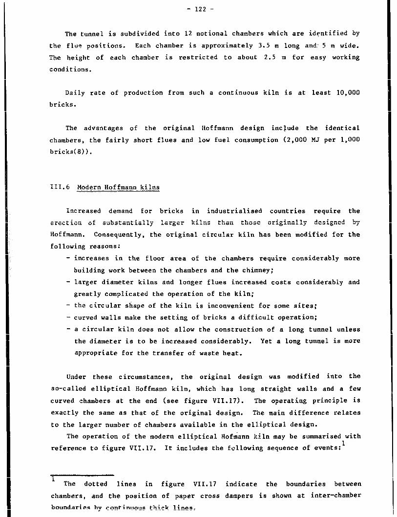
- 122 -
The tunnel is subdivided into 12 notional chambers which are identified by
the flue positions. Each chamber is approximately 3.5 m long and: 5 m wide.
The height of each chamber is restricted to about 2.5 m for easy working
conditions.
Daily rate of production from such a continuous kiln is at least 10,000
bricks.
The advantages of the original Hoffmann design include the identical
chambers, the fairly short flues and low fuel consumption (2,000 MJ per 1,000
bricks( 8) 1.
III.6 Modern Hoffmann kilns
Increased demand for bricks in industrialised countries require the
erect ion of substantially larger kilns than those originally designed by
Hof fmann. Consequently , the original circular kiln has been modified for the
following reasons:
- increases in the floor area of the chambers require considerably more
building work between the chambers and the chimney;
- larger diameter kilns and longer flues increased costs considerably and
greatly complicated the operation of the kiln;
- the circular shape of the kiln is inconvenient for some sites;
- curved walls make the setting of bricks a difficult operation;
- a circular kiln does not allow the construction of a long tunnel unless
the diameter is to be increased considerably. Yet a long tunnel is more
appropriate for the transfer of waste heat.
Under these circumstances, the original design was modified into the
so-called elliptical Hoffmann kiln, which has long straight walls and a few
curved chambers at the end (see figure VII. 17). The operating principle iS
exactly the same as that of the original design. The main difference relates
to the larger number of chambers available in the elliptical design.
The operation of the modern elliptical Hofmann kiln may be summarised with
reference to figure VXI.17. It includes the following sequence of events:’
1 The dotted lines in figure VII. 17 indicate the boundaries between
chambers, and the position of paper cross dampers is shown at inter-chamber
boundaries by continuous thick lines.

- 123 -
E .- II 0 I--= Dry
\ \ Pre-heat 1 Pre-heat Pre-heat 1 Pre-heat
- -
! z-
14
5 i-- Of-Y
--_-
3-e. heat
11 ----
3-e. heat
I Set
a -----
- _ -_ .-
-
---- ----
10 _ - - -
Fire
9 -_ -- - -
Fire
8 ----
Fire
7 - - - x
Cool
6 - - - --
Figure VII.17
Scheme for operating a modern elliptical Hoffmann kiln

- 124 -
- open wickets allow fresh air into chambers 16, 1 and 2 while bricks are
drawn from chamber 2;
- other bricks are cooled and air heated in chambers 3 to 6;
- the hot air is used for graduated combustion in the next three chambers
7 to 9;
- exhaust combustion gases are pulled by the action of the chimney through
chambers 10 to 13, thus preheating the bricks;
- gases leave the kiln at the end of chamber 13.
In this type of kiln, gases are too cool for water smoking. As they carry
much water vapour, there is a risk of spoiling green bricks by condensation
(e.g. softening of bricks, surface cracking, and scumming by salts deposited
from the products of combustion). Overcoming these problems - which may arise
with exhaust gases at less than 120°C and which are present to some extent
in the original circular Hoffmann kiln - requires a second flue which connects
all the chambers. Any of the latter may be connected or disconnected to this
so-called hot air flue by opening or closing dampers in the same manner as for
the main flue connection. In figure VII.17, the hot air flue is regarded as
being in the central island of the kiln. Some of the warmed fresh air is
taken off by the chimney suction applied to the flue. It is provided by
chambers 3 and 4 where bricks are still hot, passed down the hot air flue,
then into chambers 14 and 15 where drying, or water smoking takes place.
Hence the drying is done with clean warm air, containing no moisture or
products of combustion. This air then flows from chambers 14 to 15 into flues
(where damper are open) and is exhausted by the chimney. Meanwhile, fresh
green bricks are set in chamber 16.
The production rate of most Hoffmann kilns is approximately 25,000 or more
per day, a too large output for the type of brickworks considered in this
memorandum. However, small kilns can be built to produce only 2,000 bricks
per day(8). Figure VII.18 shows hollow clay blocks set within an elliptical
Hoffmann kiln with a capacity of about 10,000 ordinary size bricks per day.
This is an interesting kiln since wood is used for firing in place of coal
(figure VII.19). A wide variety of agricultural wastes may also be used in
place of wood in the top-fed kiln shown in tigure VII.19. For example,
sawdust has been used in Honduras (10).
Fuel consumption of elliptical Hoffmann kilns vary according to the kiln
s condition and method of operation, as mentioned in the previous section. It
is estimated at approximately 5,000 MJ per 1,000 bricks.
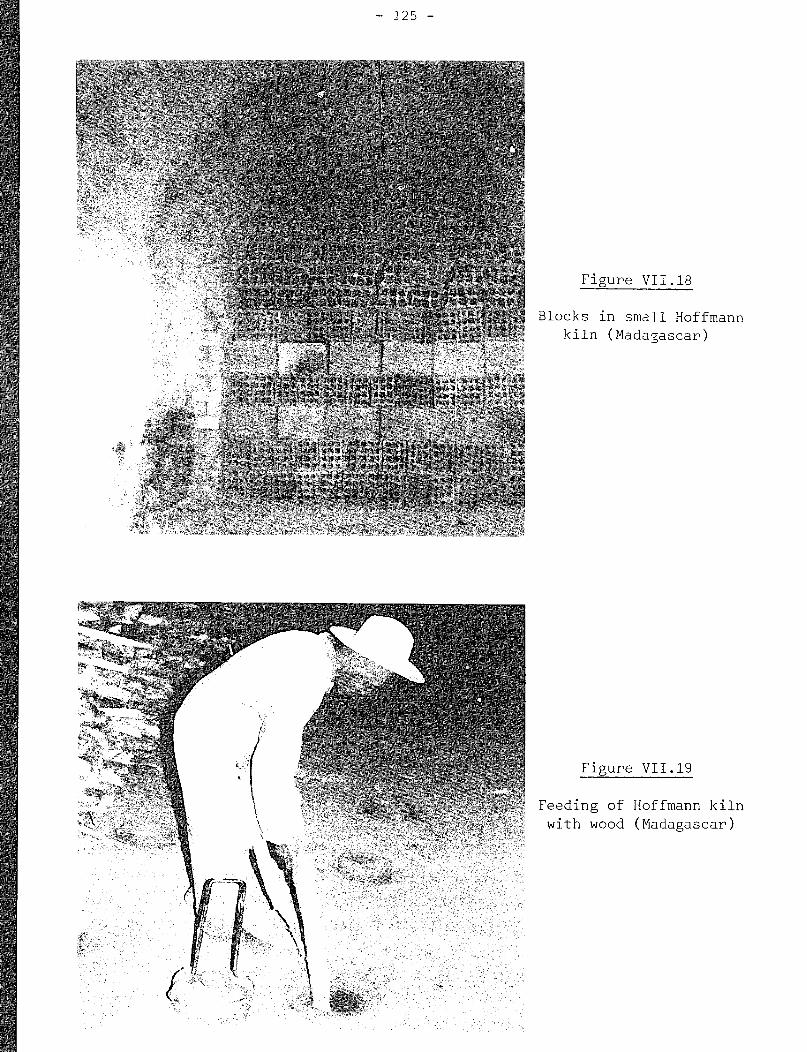
-- 125 -
Figure VII.18
Blocks in small Hoffmann
kiln (Madagascar)
Figure VII.19
Feeding of Hoffmann kiln
with wood (Madagascar)

- 126 -
VII.7 Bull’s Trench kiln
A large fraction of the cost of construction of the Hoffmann kiln is in
the building of the arch of the long tunnel, and in the provision of a
chimney, with connecting flues and dampers. Thus, the idea behind the design
of an archless kiln by a British engineer (W. Bull) in 1876.
As with the two types of Hoffmann kiln, the Bull’s trench kiln may be
circular or elliptical. Both forms have been widely used throughout the
Indian subcontinent . Construction of this type of kiln is briefly described
below.
A trench is dug in a dry soil area which is not subject to flooding. It
is approximately 6 m wide and 2 to 2.5 m deep. 1
Alternatively, especially
if the soil is not sufficiently dry, the trench may be dug to only half of
this depth, while excavated material is piled up on the trench side, and held
out off the trench by a brick wall starting at the bottom of the trench
(figure VII.20). The total length of the trench is approximately 120 m. It
is so constructed as to constitute a continuous trench.
When in operation, the Bull’s Trench is full of bricks wsrming, being
fired or cooling. Cooled bricks are drawn and new green bricks are set, while
the fire is moved progressively around the kiln. The exhaust gases are drawn
off through 16 m high moveable metal chimneys with wide bases, which fit over
the openable vent holes set in the brick and ash top of the kiln. These
chimneys are guyed with ropes to protect them from strong winds. The type of
chimneys shown in figure VII.21 require six men to move them. This figure
also shows the method of fueling whereby small shovelfuls of less than 1.5 cm
size coals are transferred Erom storage bins on top of the kiln, and sprinkled
in amongst the hot bricks through the removable cast-iron feed holes. Metal
sheet dampers are used within the set bricks to control draught.
Figure VII.22 shows the sequence of events diagramatically. The setting
of the bricks within the kiln must be such as to allow sufficient air flow
between the bricks and wide enough spaces for the insertion and burning of
fume1 and the accumulation of ashes. However, the whole setting must be
sufficiently strong and stable to ensure safe operation of the kiln. The
setting in figure VII.20 shows occasional cross link bricks, between the
separate bungs or pillars of bricks, tying bungs together. Information on the
firing of these kilns is available (54) and kiln designs are standardised(55).
Modifications to this type of kiln have involved the provision of flues
from the trench so that chimneys can be moved on rails located on
1 Excavated soil may be suitable for brickmaking.

- 127 -
Figure VII.20
Cross-link bricks between the separate
bung5 or pillars of bricks in Bull's Trench kiln

- 128 -
Figure VII.21
3uilf s Trer,ch kilr.: chimnelr and fepiing (India)
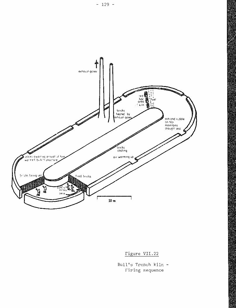
- 129 -
Figure VII.22
Bull's Trench kiln -
Firing sequence
- 130 -
the centre island rather than over the setting bricks in the kiln. A major
problem is the corrosion of the mild steel chimneys normally used. They may
rust through within only a few months. Accordingly, some kilns have been
redesigned with dampers opening to flues connected to a permanent brick
chimney.
The whole Bull’s Trench kiln is very large, a normal output being 28,000
bricks per day. With a narrow trench output could be reduced to 14,000 bricks
per day. It is not possible to shorten the trench as this will affect the
heat transfer efficiency. The depth of the trench cannot be reduced either
without impairing the firing behaviour. The kiln would be very big to roof
over, and is most suited to dry weather conditions. The chief advantage of
this type of kiln is its low initial construction costs.
Fuel consumption is much better than in intermittent kilns, 4,500 MJ being
required for firing 1,000 bricks (10, 22, 56). About 70 per cent first-class
bricks can be obtained, the remaining bricks being of poorer quality.
III.8 Habla kiln
The effective tunnel length of the Hoifmann type kiln may be increased by
the building of zigzagged chambers. The resulting kilns, known as the zigzag
ki Ins, have a faster firing schedule than the Hoffmann kiln. However, they
require a fan - and therefore electrical power - as air must travel a longer
path and a simple chimney does not provide sufficient Araught for air
c irculat ion. Fans provide a more steady draught than chimneys and can be
better controlled. They allow a larger transfer of heat to the water-smoking
stage, thus saving fuel. However, it is best to avoid condensation on fan
blades and subsequent corrosion of the latter by having gases extracted at
12oOc. This is especially import ant if fuel or clay contain sulphur
compounds such as pyrites which are transformed into sulphuric acid in the
kiln gases.
The zigzag kiln developed by A. Habla is an archless kiln. One addit ional
simplifying feature of this kiln is that the zigzagging walls are temporary
structures of green bricks which may be sold after firing. Habla kilns are of
various designs: in some kilns the flues are returned from all chambers to the
central island while in others, some of the flues are returned to the outer
walls. Figure VII.23 illustrates the former type of kiln. For simplicity, it
omits the hot air flue which can be carried above the main flue for providing
clean drying air.
The Habla kiln is rectangular, but close to a square. The one illustrated
in figure VII.23 has chambers numbered 1 to 20, every second chambers being

Seclion at A-A
Figure VII.23
Habla type kiln - Firing sequence
- 132 -
accessible through a wicket. Partition walls of dried green bricks, with a
thickness of only one brick length, are alternatively built out from the
central island and the outer wall. These partition walls deflect the gases
from the island to the outer wall, through the wide-set bricks between the
part itions. As the temperature of any particular chamber rises, the wide-set
bricks are first heated. Then, as bricks in the partition shrink a little,
draught through the partitions increases, and the bricks in that partition as
well as the wide-set ones become fired.
In figure VII.23, chambers 1 and 2 are empty. Bricks are drawn from
chamber 3. Air passing through the open wickets is warmed as it cools bricks
in chambers 4 and the following ones. After the firing zone, the exhaust
gases preheat bricks, flow out of chamber 15 through the chamber flue and open
damper (shown in the section drawing), and enter the main flue from where they
are expelled through a short chimney by the fan. Bricks in chambers 16 to 19
are water smoked by clean warm air from chambers 4 to 6. Paper dampers are
used as in the case of the Hoffmann kiln.
An interesting modification to the layout shown in figure VII.23 is to
build a pair of short partitions in line with each other, approaching from the
island and outer wall, but leaving a gap in the middle, Secondly, a wall may
be built in the middle of the kiln, separated by two gaps from the island and
outer walls. The fire can then travel along two paths simultaneously, around
both ends of the second partition, through the central gap of the third, then
around both sides of the fourth and so on. This modif ication should help
speed the rate of firing.
Large Habla kilns, producing 25,000 bricks per day (571, have been built
in a number of countries. Recently, in India, a 24-chamber high-draught kiln
of this type has been developed (58) for an output of 30,000 bricks per day.
It is fired with coal and wood. Figure VII.24 is based on published
information on this Indian kiln. The latter may be reduced in size for a
production of 15,000 bricks per day. Roofed zigzag kilns may also be built
for as few as 3,000 bricks per day (8).
The Habla kiln is economical to construct and operate. It has a larger
capacity relative to its area than other continuous kilns. This feature
reduces the costs of land and construction. Furthermore, the kiln has a long
firing zone, allowing difficult clays to be fired more easily. The
long-f iring path assists heat exchange between gases and bricks, thus
improving fuel efficiency. Because partitions are of green bricks, less
permanent brickwork has to be heated and cooled, thus adding to fuel
efficiency. The shrinkage of bricks in the partiL -ens and consequent leakage
of hot gases shortens the distance travelled by the latter. Thus, less power
is needed to drive the
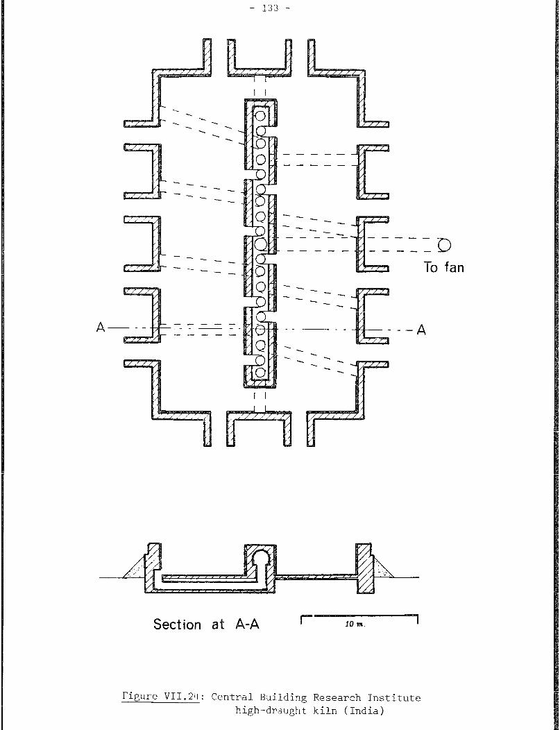
- 133 -
A ---
-* . .
. . . . . .
-
-
-- ---
-- -- ---
--
--- --- 33
-r0 fan
Section at A-A
Figure VII.24: Central Building Research Institute
high-draught kiln (India)

- 134 -
fan. As a result of partition leakage, the kiln has relatively few “dead
spaces” where heat is insufficient to fire bricks properly. The building of
partitions of green bricks at the start of each operation does not increase
labour costs since the bricks are removed for sale and may thus be regarded as
part of the whole setting. Another advantage of the Habla kiln is the easy
access ‘;o the structure.
Fuel consumption of a zigzag kiln is estimated at 3,000 MJ per 1,000
bricks(57). Consumption in the high-draught Indian archless kiln is also
approximately 3,000 MJ per 1,000 bricks.
IV. AUXILIARY EQUIPMENT
IV.1 Kiln control
Temperature control, including control of the temperature attained and of
the z-ates of increase and decrease, is an essential activity in brickmaking.
Such control may be carried out in a number of ways, including the following:
Analysis of the colour of gases roming off the kiln: During the initial
stage of heating (water-smoking) white gases indicate that the bricks are not
thoroughly dry. Thus, the fires must be kept low. The presence of wetness on
an iron bcr withdrawn from the kiln after only a few seconds’ insertion is
indicative of the water-smoking stage. From approximately 500°C upwards,
the colour of the hot kiln provides clues to the temperature attained. The
interpretation of kiln coiours should be based on previous temperature
readings and colour examination. For example, the colour of smoke of a stove
kiln varies as the whole kiln reaches top temperatures. The sink of the
bricks is also an indication of the process of vitrification.
Use of instruments: Instruments are also available to assist the kiln
operator. At the water-smoking stage, a thermometer within a protective metal
sheath may be pushed in or lowered on a chain amongst the bricks. The
presence of moisture on the metal (after withdrawal of the thermometer) is
indicative of the water-smoking stage. A reading of the temperature may be
obtained by keeping the thermometer amongst the bricks for a ionger period.
While moisture is still being driven off, the temperature remains at about
1ooOc. Once it rises to 120°C, fires may be increased as moisture in the
bricks will have been removed. Thermocouples may be used in place of
thermometers especially if a cant inuous reading of the temperature is
required. A chart recorder, which displays the temperatures measured by
several thermocouples, may be used for this purpose. In a continuous kiln,
thermocouples could be placed in the
- 135 -
preheating zone, tha maximum temperature firing zone, in the coolest part of
the cooling chamber from which air is being taken to the chimney, in the base
of the chimney Gild in the hot air flue if it exists (48). A reading of the
chart will indicate the state of the kiln and the need to adjust firing in
order to obtain better quality bricks or to improve fuel efficiency. It also
gives the manager an indication of the quality of the kiln operation.
Thermocouple probes must be of a corrosion-resistant metal or in protective
sheaths.
Pyrometric cones, which better measure the effect of both time and
temperature upon clay, may be used in place of thermocouples. They are made
from carefully controlled mixes of clays and fluxes, and will therefore
deform, or squat at different stages in a heating schedule. For example, a
cone which squats at 1,140°C with a rire of 60°C per hour, will squat at
1,230°C with a temperature rise of 300°C per hour. Thus, pyrometric cones
indicate the way in which fired clay products perform in a kiln. The
temperature at which cones squat, when heated at a standard rate, is known as
the pyrometric cone equivalent (PCE) . Cones may be used in laboratory
experiments and in full-size production kilns, and are useful in applying the
results of laboratory investigations. In practice, three cones are used to
control the firing temperatures within a kiln at a given PCE: one cone of the
adopted PCE value, one of 0
20 C less, and one of 0
20 C more. These cones
are set in a fireclay base and placed between bricks well in from the kiln
wall but in line with a plugged spy hole, sealed with clay. The cones are
checked periodically until the first cone, with the lowest PCE rating, begins
to bend over. The fire should then be stocked less as the cone with the
highest PCE rating should not be allowed to squat. In other words, only the
first and second cones should squat. Squatting of the third cone indicates
that the kiln has been heated beyond the intended temperature. Sets of cones
can be placed amongst the bricks remote from the holes in order to check
temperatures attained in any part of the kiln. Alternative systems, using
rings or bars, are also used.
Draught gauges, consisting essentially of water-filled, open-ended U-tubes
of glass, may be used to measure the draught or suction at any given point of
the kiln by connecting one end of the tube to a chamber or chimney and
measuring the difference in water levels in the tube. This gives a quick
check on the kiln’s functioning, and indicates whether dampers should be
adjusted.
It is good practice to keep a record book of all kiln operations,
including temperatures, draught, numbers and sizes of bricks set, and the
number and size of saleable bricks of various grades. The quantity of fuel,

- 136 -
operators on duty and any incidental remarks about wind, rain, etc. should be
noted in the record book.
IV.2 Brick handling
Labour costs may be substantially lowered if the handling of bricks (e.g.
green, dried, and fired bricks) can be rationalised, and if efficient
transport devices are used. Furthermore, these devices can be of considerable
assistance in relieving the burden of workers. A simple litter borne by two
people can be used for the transport of bricks as in the case of clay. The
crowding barrow (figure VII.251 is extremely useful, especially in confined
spaces such as in the circular downdraught kiln. The barrow is short, with
its wheel well placed under the load which may be stacked high. The balance
of the barrow is adjusted by placing the bricks according to the workers’
height. Thus, little weight- is taken on his hands and the load does not tip
forward.
V. FUEL
Given the high prices and scarcity of many fuels, achievement of fuel
efficiency becomes an important factor in brickmaking. Table VII. 1 compares
typical requirements of the different kilns described in Section III. It must
be appreciated that actual amounts could vary widely from those given,
depending upon the size of kiln, size of bricks, nature of clay, firing
temperature, the condition of the kiln, and the skill of the operators.
Galorific values of wood, coal and oil have been taken as 16,000, 27,000 and
44,000 MJ per tonne respectively. Figures in brackets indicate that the fuel
is not suitable for a particular kiln.

- 137 -
Figure VII.25
Crowding barr.ow

- 138 -
Table VII.1
Typical fuel requirements of kilns
Type of kiln
Heat requirement
(~~/1,000 bricks)
Quantity of fuel required
(Tonnes/l,000 bricks)
Wood Coal Oil
Intermittent
Clamp
Stove
Scotch
Downd raugh t
7,000 (0.44)
16,000 1.00
16,000 1.00
15,500 0.97
Continuous
Original Hoffmann 2,000 0.13
Modern Hof fmann 5,000 0.31
Bull’s Trench 4,500 0.28
Habla 3,000 0.19
Tunnel 4,000 (0.25)
Source:5, 8, 10, 22, 24, 33, 44, 52, 56, 57, 58.
0.26 (0.16)
0.59 0.36
0.59 0.36
0.57 (0.35.)
0.07
0.19
0.17
O,.ll
(0.15)
0.05
0.11
(0.10)
(0.07)
0.09
Where wood is used as a fuel, trees should be replanted to replenish
supplies. Sometimes s commercial ventures provide an incidental supply of wood
(e.g. in the rubber estates, where trees fulfil their latex-yielding life
within 30 years or so). The practice of coppicing is worthwhile: small-size
wood is cut from a low level, thus allowing the trees to continue to grow.
Coppicing may yield 125 tonnes of wood every year from a square kilometre (22).
Many other materials can be utilised to assist in the firing of bricks, in
addition to wood, coal and oil. Gas, either naturally occurring such as Sui
gas in Pakistan, or made from plant wastes by gasification OL by bio
degradation processes (biogas), may be burnt in simple burners, preferably set
low down in the kiln.
- 139 -
Agricultural and plant wastes may also be used for firing, including
sawdust (e.g. in Honduras (10)) and rice husk (e.g. in experimental kilns and
in a Bull’s Trench kiln in Pakistan). A large quantity of ash, some 18 to 22
per cent of the weight of the husk, is produced on burning. As this ash may
block the bottom of the Bull’s Trench kiln, coal is L ’ cqithout husk on every
few blades. Groundnut husks, coffee husks, chaff, straw and coconut husks
have also been used on an experimental basis. They may be burnt in the grate
of an intermittent kiln, or fed in through the top of Hoffmann, Bull’s or
Habla kilns. However, the volume required for sufficient heating is very
large in most cases. These wastes may not be easily burnt in kilns equipped
with grates. They may therefore constitute only part of the fuel source.
Dung is a traditional fuel in Sudan.
Waste materials may also be mixed with clay (e.g. 5 to 10 per cent by
weight! instead of being directly used as a fuel source. While this method is
technically feasible, it may produce more porous and weaker bricks.
Other wastes have been tried in a number of kilns. These include old
rubber tyres, waste engine oil, ashes, clinker, pulverised fuel ash from
coal’-fired power stations, and coal washery wastes.
The optimum air flow for highest fuel efficiency in a kiln can be
determined by experiment, especially if good records are kept. Adequate air
is necessary to obtain full combustion of fuel. However, too much air will
have a detrimental cooling effect.
The best use of fuel is generally obtained in continuous kilns, properly
maintained and run, using a fraction of waste materials. Economy of scale
favours the larger kilns, but fuel for transportation of bricks from a
large-scale plant may negate the fuel savings from the operation of the kilns.
VI. PRODUCTIVITY
The range of outputs of the various kilns described in Section III is
shown in table VII.2 Although smaller units might be built than those quoted,
lack of data on these units precluded their inclusion in the table.

- 140 -
Table VII.2
Type of kiln Capacity (bricks, ‘000s) Capacity (bricks per day, ‘000s)
Intermittent
Clamp
Stove
Scotch
Downdraught
10 - 1,000
5 - 100
15 - 25
10 - 50
Continuous
Original Hoffmann
Modern Hof fmann
Bull’s Trench
Habla
10 - 15
2 - 24
14 - 28
15 - 30
Many factors affect the obtained outputs. In general, good maintenance
and provision of roofs over kilns will improve the quantity of bricks
produced, but will add to costs. Quantities produced will also depend upon
the required qua1it.y standard and the skill of the operators. The market
demand, weather, infrastructure and sUpply of raw materials will govern the
rate at which production may proceed.
Capital-intensive equipment is available for transportation and the
setting of bricks, but all the kilns described in Section III may be operated
on a labour-intensive basis. All but the downdraught and Hoffmann kilns
involve the extra task of covering the green bricks witn previously burnt onec
and ashes.
Most of the kilns described in this memorandum are operated on a fairly
labour-intensive basis. Table VII.3 shows the difference in labour
requirements between these kilns and more automated kilns used in
industrialised countries.
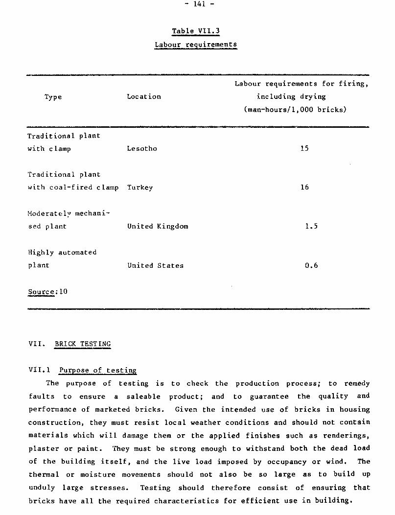
- 141 -
Table VII.3
Labour requirements
Type Location
Labour requirements for firing,
including drying
(man-hours/l,000 bricks)
Traditional plant
with clamp Lesotho 15
Traditional plant
with coal-f ired clamp Turkey
Moderately mechani-
sed plant
Highly automated
plant
United Kingdom
United States
16
1.5
0.6
10 Source:
VII. BRICK TESTING
VII.1 Purpose of testing
The purpose of testing is to check the production process; to remedy
faults to ensure a saleable product ; and t 0 guarantee the quality and
performance of marketed bricks. Given the intended use of bricks in housing
construction, they must resist local weather conditions and should not contain
materials which will damage them or the applied finishes such as renderings,
plaster or paint. They must be strong enough to withstand both the dead load
of the building itself, and the live load imposed by occupancy or wind. The
thermal or moisture movements should not also be so large as to build up
unduly large stresses. Testing should therefore consist of ensuring that
bricks have all the required characteristics for efficient use in building.

- 142 -
VII.2 Initial checks on quality
11 quick check of quality consists in striking two hand-held bricks. A
high-noted ring indicates that they have been thoroughly fired. On the other
hand, a dull sound indicates either cracked or soft-fired material.
Similarly, bricks which cannot be scratched and rubbed away with the edge of a
coin are hard and of good quality. Nevertheless, bricks without a good ring
or which can be marked may still be perfectly suitable for many construction
purposes. These two tests only serve to identify some of the best materials.
The general appearance of bricks may give a quick indication of quality.
Regular shapes and sizes, sharp arrises, unblemished surfaces and freedom from
cracks are signs a’f good bricks. Colour is difficult to interpret. However,
within a batch of bricks from any one brickworks, the darker colours are
likely to relate to the harder fired, stronger and more durable bricks.
VII. 3 Standard specifications
Many countries have published their own standard specifications for
bricks, and refrerence sho::ld be made to these where available. The methods
of testing described in the British Standard(37) have been devised after much
research and many years of experience, and are of wide interest. However, Lhey
may not necessarily be appropriate for other countries. Actual numerical
limits must be decided locally according to what is required and what can be
made.
VII.4 Sampling
The testing of bricks should be made on a representative sample of the
latter since variations in preparation of raw materials, drying and firing
produce bricks of variable characteristics. The testing sample should
preferably contain 40 bricks picked up at random while they are being unloaded
from the kiln. It is more difficult to obtain random samples once they have
been placed in a large stack.
VII. 5 Dimensions
Since bricks are used in fairly long runs, the testing of brick dimensions
need not be carried out on individual bricks. Instead, 24 bricks should be
chosen at random from the sample 40 bricks and small blisters or bumps knocked
off. The 24 bricks should then be placed against an end stop touching end to
end on a long bench. If the nominal length of each brick must be, for
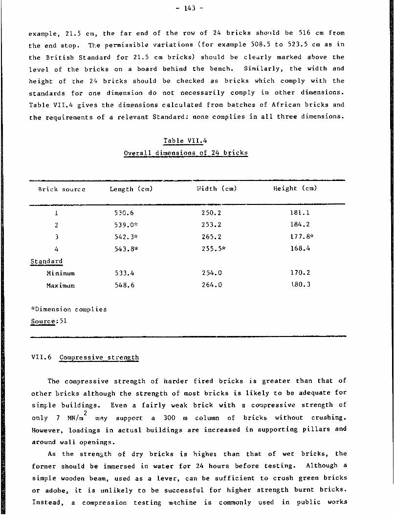
- 143 -
example, 21.5 cm, the far end of the row of 24 bricks sholtld be 516 cm from
the end stop. The permissible variations (for example 508.5 to 523.5 cm as in
the British Standard for 21.5 cm bricks) should be clec;rly marked above the
level of the bricks on a board behind the bench. Similarly, the width and
height of the 24 bricks should be checked as bricks which comply with the
standards for one dimension do not necessarily comply in other dimensions.
Table VII.4 gives the dimensions calcul.ated from batches of African bricks and
the requirements of a relevant Standard: none complies in all three dimensions.
Table VII.4
Overall dimensions of 24 bricks
Brick source Length (cm> Width (cm) Height (cm>
1
2
3
4
Standard
Minimum
Max imum
533.6 250.2 181.1
539.09 253.2 184.2
542.3* 265.2 177.8*
543.8* 255.5* 168.4
533.4 254.0 170.2
548.6 264.0 180.3
*Dimension complies
Source: 51
VII.6 Compressive strength
The compressive strength of harder fired bricks is greater than that of
other bricks although the strength of most bricks is likely to be adequate for
simple buildings. Even a fairly weak brick with a compressive strength of
only 7 MN/m2 may supper-t a 300 m column of bricks without crushing.
However, loadings in actual buildings are increased in supporting pillars and
around wall openings.
As the strength of dry bricks is highet than that of wet bricks, the
former should be immersed in water for 24 hours before testing. Although a
simple wooden beam, used as a lever, can be sufficient to crush green bricks
or adobe, it is unlikely to be successful for higher strength burnt bricks.
Instead, a compression testing machine is commonly used in public works

departments, universities, and technical and research institutes. To avoid
high local loadings due to small irregularities on the bed faces of bricks in
contact with the steel plattens of the machine, thin plywood plattens should
be placed on both bed faces. Bricks with frogs or large perforations should
be bedded in mortar which is allowed to set prior to testing. Ten bricks
should be tested, and the mean strength calculated.
Table VII.5 gives test results obtained on batches of bricks from two
differ-ent works in East Africa. The:7 were tested by the British Standard
method. Although a few individual bricks from one works are weaker than
required for a particular grading (not the lowest), the mean value complies
with the standard requirement. Similarly, a few bricks from the other works
would not meet a requirement of the Indian Standard(361, but the mean value is
satisfactory.
Table VII. 5
Compressive strenpth of 10 bricks
Brick source Compressive strength MN/m2
Individual bricks Mean Minimum requirement
British Indian
Ordinary Class II
A 4.1, 430, 8.1, 8.1, 7.1 5.2 7.5
11.1, 10.9, 7.7,
4.0, 6.1, 7.1
6.2, 6.5, 6.5, 8.8
11.4, 7.7, 11.5,
6.3, 10.3, 9.9
8.5
Source: 61
For calculatr? load-bearing structures and civil engineering works, the
strength of the bricks should be determined and used in the design
calculations.
For non-load-bearing partitions, bricks of only 1.4 MN/m2 may be
used(37).
- 145 -
A low-cost impact testing method, claimed to give useful information on
brick strength, consists in dropping a weight several times on the pieces of a
broken brick in a containing cylinder(62).
The density of dry bricks is easily determined, and is sometimes quoted
instead of strength.
VII.7 Resistance to e
Although compressive strengths may be more than adequate, dampness and
flowing water can cause severe deterioration in buildings. Unfired earth
bricks or adobes are eroded or slaked by water. On the other hand, firing
yields bricks wi:h excellent resistance to water erosion. The testing of
resistance to erosion by water requires the soaking of brick samples in water
for 24 hours. Good bricks should show no sign of softening or slaking.
A more severe test consists in spra;ling water on bricks for several
weeks. This test allows the separation of bricks into various quality groups
as lowquality bricks get eroded while high-quality ones remain unaffected.
VII.8. Water absorption
Hard fired bricks will
quantity of water absorbed
absorb less water than other types of bricks. The
by a dry sample of bricks, when immersed in water
for 24 hours or eight days(7), or boiled for five hours(37) is often estimated
in testing laboratories. However, the results of this simple test are not
easy to interpret. -Generally) absorptions of less than 15 per cent by weight
in the cold tests would be indicative of satisfactory brick strength and
durability. Bxceptionally, higher absorptions may be found with some ty[JeS of
clay although the bricks may still be satisfactory.
VII. 9 Rain penetration
In practice, moderately high water absorption is acceptable in a brick
wall, since rain water dries out once good weather conditions return. On the
other hand, under some circumstances, rain running on walls made of low
absorption bricks may enter the wall surface through small cracks between
bricks and mortar. Rain penetration tests may be set up by building walls
exposed to either rain or a water spray on one side, and observing the other
sheltered side of the wall. The quality of not only the bricks but also of
the workmanship in laying them, is of significance in determining the
performance ?f the brickwork.

- 146 -
VII.10 Efflorescence, soluble salts and sulphate attack
Appearance of efflorescence on brickwork is considered unsightly and in
extreme cases may cause spalling of faces of bricks. It may occur on initial
drying or after subsequent wetting of the bricks. One test for determi.ning
the presence of ef florescence consists in half immersing bricks in distilled
water for two weeks. Soluble salts, if present, will dry out on the top
corners of the bricks as water is being soaked up. If only slight
efflorescence occurs, it may be assumed that no problems are likely to arise
in practice(7). Alternatively, sample bricks can be covered with a polythene
sheet to prevent evaporation from the non-visible face in the finished
brickwork, while exposing the other face upwards. A bottle of distilled water
is then inverted on this latter face and the water allowed to soak in.
Subsequently, the water dries out, and salts present in the bricks are carried
to the surface where the amount of such salts may be estimated. Generally, if
more than half of the exposed area is covered with salts, or if the surface
flakes, the bricks would be regarded as efflorescent(37).
The nattire of soluble salts can be determined in the laboratory by
standard methods of chemical analysis carried out on powder obtained by
drilling or fine grinding of brick samples. More than 3 per cent by weight of
salts is considered a high concentration. For special quality brickwork,
acid soluble sulphates should not exceed 0.5 per cent, calcium 0.3 per cent,
magnesium 0.03 per cent, potassium 0.03 per cent and sodium 0.03 per cent(37).
VII.11 Lime blowing
Hydration of quicklime particles derived from limestone in brickmaking
clays can cause pitting on brick faces. When, in spite of precautions in
manufacture, a problem persists, it may be possible to alleviate it by docking
the bricks (i.e. by immersing them in water(50)). Docking apparently slakes
the lime to a softer form which may extrude into neighbouring brick pores.
Bricks should be soaked for approximately 10 minutes so that water penetrates
at least 15 mm. Otherwise, the problem may worsen. Large quantities of water
are required, and the increased weight of the bricks may add to transportation
costs. Efflorescence may appear as the water dries out.
Testing for lime blowing can be done by immersing brick samples into
boiling water for 3 minutes(50), or preferably into a steamy oven(63).

- 147 -
VII. 12 Frost
Frost is one of the most destructive natural agents but only when
brickwork is frozen while in a very wet condition. In climates where frost
occurs, outdoor test walls or laboratory freezing and thawing tests can be
used to assess frost resistance(l0, 64). Harder fired, less porous bricks are
generally more resistant to frost.
VII.13 Moisture and thermal movement
Reversible and irreversible moisture movements are likely to be small and
of little consequence for small buildings. Tests can be carried out to
determine these movements if bricks are to be used for long runs of brickwork,
or in tall structures. Thermal expansion is of similar significance and may
be measured: it is likely to be approximately, 4 x 10⁻⁶ m per ‘C (i.e. a
change in temperature of 20°C will cause a 12 m run of brickwork to change
1 mm in length).
VII. 14 Durability and abrasion resistance
To investigate performance, including resistance to abrasion by wind-blown
sand, small test walls should be constructed outdoors from the various types
of bricks made at any works. Changes in the brick surface over various
periods of time will indicate the degree of resistance of bricks to abrasion.
VII.15 Use of substandard bri.cks
Bricks that do not meet the required standards may be used for other
purposes, and not be entirely wasted.
Underburnt bricks may be returned for refiring, or may be useful in kiln
construction. Overburnt bricks may also be used in kiin construction or can
be broken up and used as concrete aggregate.
Reject bricks may be broken up and used for road building or sos.kaways.
If finely ground, they may be used as grogs in brickmaking.
Reject, underfired bricks exhibit pozzolanic properties when ground down
to powder. The latter may thus be mixed with lime for the production of a
cement substitute. Alternatively, the lime released when ordinary Portland
cement sets will react with the brick powder. Thus, crushed soft-f ,ired clay
could constitute a useful mortar ingredient.

CHAPTER VIII
MORTARS AND RENDERINGS
I. PURPOSE AND PRINCIPLES
Mortar is used to accommodate slight irregularities in size, shape and
surface finish of bricks, thus providing accuracy and stability to a wall. In
so doing, gaps between bricks are also closed, thus excluding wind and rain
and increasing the wall strength.
Rendering applied to the external surface of brick walls can help prevent
ingress of rainwater into a building. However, if materials are of good
quality and bricklaying techniques are correct, rendering is usually
unnecessary. Rendering is preferred, in some countries, for mainly aesthetic
reasons while bare fair-faced brickwork is preferred in others.
In general, mortars need not be stronger than the bricks, and renderings
should be mixed and used so that they do not crack (see section III).
Mixes for mortar and render are frequently made from ordinary Portland
cement or lime, together with a large proportion of sand. In principle, a
good solid mortar should contain two-thirds sand and one-third binder. If
less than a third is used, the wet mix will be less workable and less strong
when set. If more than a third is used, greater shrinkages will occur, and
the risk of cracking will increase. Furthermore, the cost of mortar will be
unnecessarily high.

- 150 -
II. MORTAR TYPES
II.1 Mud
The most elementary mortar, mud, is made from soil mixed with water. It
may be suitable for laying adobe, but is not recommended for fired bricks.
Mud mortar exposed to the weather in fair-faced work will quickly be eroded by
wind-blown sand and rain (figure VIII.1). A good-quality rendering is
essential if mud mortar is used. However, cement used in the render mix will
be better utilized in making a more durable mortar.
IT.2 Bitumen/mud
The addition of bitumen as a cut-back or emulsion makes a mud more
water-resistant. Asphalt may be used as an alternative material.
II.3
Mud renderings may be made more weather-resistant by the incorporation of
cow dung. A thin paste made by adding water to a mix of one part cow dung
with five parts of soil may also be used to wash over a mud rendering(20).
II.4 Lime/sand
Lime and sand mixes are traditional materials. Lime varies in purity and
thus gives different types of mortar. If the lime is very pure, consisting of
a large proportion of calcium hydroxide, the hardening of the mortar will be
due solely to carbonation, caused by the slow reaction with carbon dioxide in
the air. On the other hand, impure limes often contain a proportion of
siliceous material from clay contained in the limestone. In this case, lime
burning yields a hydraulic lime, which sets under water if needed. The
hardening is in this case a reaction between silica and calcium hydroxide
which gives calcium silicate. Hydraulic limes also carbonate in air. This
type of mortar can be very good, but slow hardening makes it less attractive
than cement mortars. Replacement of some 1Fme by cement gives a useful
se in early strength.
sential that lime b completely slaked before use. Commonly,
slaked lime may be. purchased as such, and quality may well be satisfactory.
Alternatively, n be used, but it must first be mixed with water in
a pit. A slight excess of water should be added, and the mixture covered to
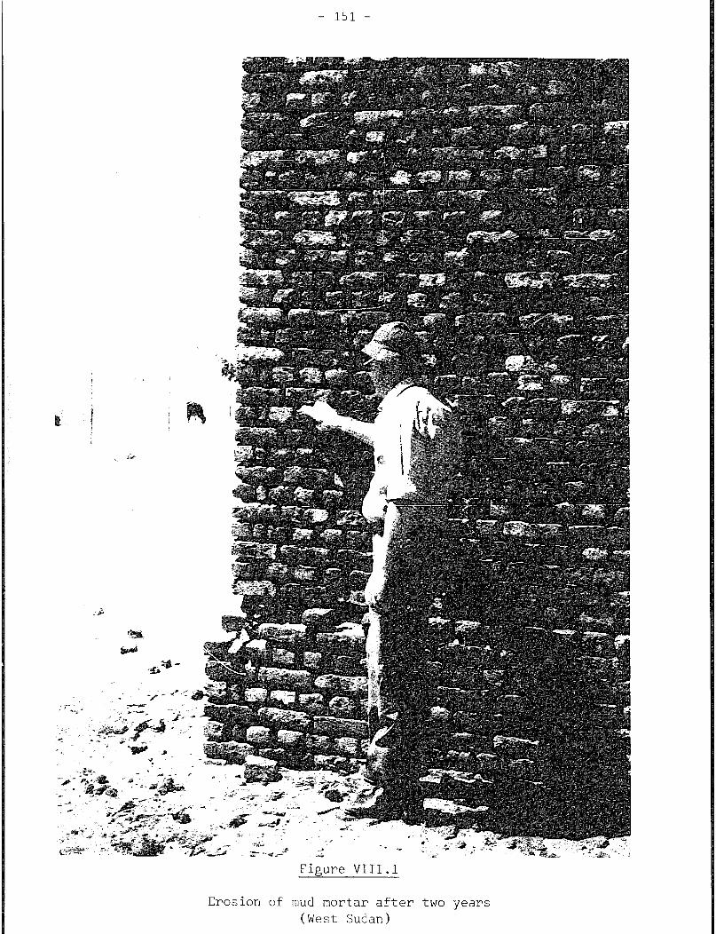
Figure VIII.1
Erosion of mud mortar after two years
(West Sudan)
- 152 -
prevent drying out. Several days in the slacking pit are needed for its
hydration. If any particles of unslaked material remain, they may slake later
in the set mortars, and spoil the mortar.
II.5 Pozzolime
In the same way as silica from the clay heated during lime-burning could
react with lime as described earlier, so naturally occurring volcanic ashes
may contain siliceous material which can have a pozzolanic reaction with
lime. In Tanzania, three parts of ash and one of lime are mixed together to
form a "cement". The latter is then mixed with sand for the production of
mortar(65).
II.6 Rice husk ash cement #
Rice husks burnt at temperatures below 750°C yield approximately 20 per
cent of their weight in pure ash. A cement-like material can be produced by
mixing two parts by weight of this ash with one part of lime (66). One part
Of this rice husk ash cement may then be mixed with three parts of sand (by
volume) and water for the production of mortar or rendering.
A similar material can be made from rice husks and lime sludge waste
derived from sugar or paper industries(67).
II.7 Brick-dust/lime
Brickmaking clays fired to only 700°C produce a pozzolanic material
when crushed to a fine powder. Two parts of the latter (known as surkhi in
India) are mixed with one part of lime for the production of a cement-like
material. The latter may then be mixed with sand for the production of mortar
(68).
II.8 Ordinary Portland Cement( OPC)
OPC is widely used for mortars and renderings. Excessively strong mixes
may be harmful and unnecessarily expensive. Where sulphates from bricks cause
problems by reacting with OPC mortars, the use of sulphate-resisting cement
might be considered.
- 153 -
II.9 Pulverised fuel ash
Pulverised fuel ash from modern coal-fired electricity generating plants
exhibits pozzolanic properties. 30 per cent of this material may be mixed
with 70 per cent of ordinary Portland cement for the production of pozzolanic
cement. Pulverised fuel ash may also be used with lime. The Indian
standard(69) for this and other pozzolanic materials requires that mortar
cubes of one part pozzolanic mixture and three parts sand by weight show an
initial set in not less than two hours, and a final set within one,
one-and-a-half, or two days, depending upon grading. For these three grades,
2 8-days compressive strengths should be at least 4, 2 and 0.7MN/m2
respectively.
II. 10 Plasticisers
Mixes of ordinary Portland cement and sand are made more workable by
substituting lime for some of the cement. The wet mix is then buttery and
easy to spread by the masons. Instead of lime, very small additions of
purpose-made vinsol resins may be added. The latter form ‘minute bubbles
during mixing. However, it is difficult to obtain a mortar with the required
properties as the mixing operation cannot be easily controlled. Factors
affecting the properties of the mortar include the amount and hardness of
water in the mix; cement content; fineness and composition; grading of the
sand; and the efficiency and duration of mixing. Unless all these factors are
properly controlled, problems may arise. For example, the mortar may squeeze
out after several courses have been laid, and the brickwork may get out of
vertical alignment if too much air is incorporated in the mix. Furthermore,
strength may decrease and mortar may become too permeable to water after
setting. On the other hand, too little air will reduce the mortar
workability. Thus, spreading of mortar may not be carried out properly,
resulting in low strength brickwork and poor resistance to rain
penetrationc 70).
Masonry cements (made with ordinary Portland cement and plasticisers)
should show an initial set in not less than 45 minutes, and a final set within
10 hours, if they are to comply with the British Standard(71). A 28-days
compressive strength should not be less than 6 MN/mL.
II.11 -sum plaster
Any substance which sets from a fluid into a solid may be regarded as
cementitious(72). Gypsum plasters, made by heating naturally occurring (or
industrially produced) gypsum will set quickly. They have been used as mortar
in arch building without centring. Being slightly soluble in water
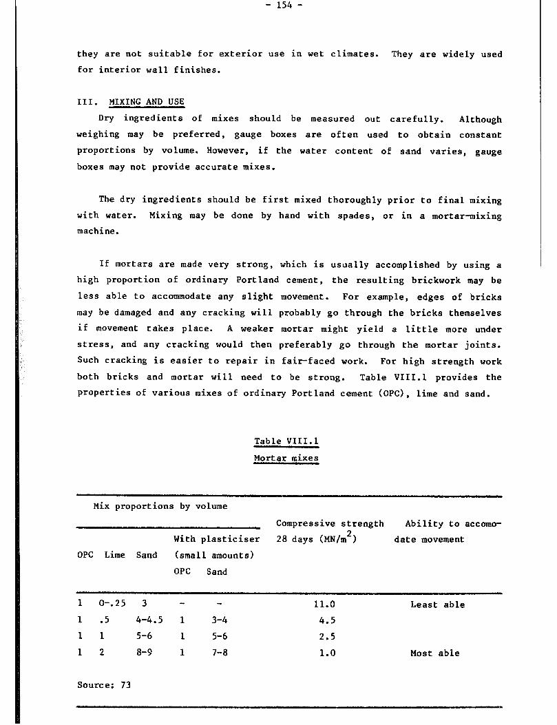
- 154 -
they are not suitable for exterior use in wet climates. They are widely used
for interior wall finishes.
III. MIXING AND USE
Dry ingredients of mixes should be measured out carefully. Although
weighing may be preferred, gauge boxes are often used to obtain constant
proportions by volume. However, if the water content of sand varies, gauge
boxes may not provide accurate mixes.
The dry ingredients should be first mixed thoroughly prior to final mixing
with water. Mixing may be done by hand with spades, or in a mortar-mixing
machine.
If mortars are made very strong, which is usually accomplished by using a
high proportion of ordinary Portland cement, the resulting brickwork may be
less able to accommodate any slight movement. For example, edges of bricks
may be damaged and any cracking will probably go through the bricks themselves
if movement takes place. A weaker mortar might yield a little more under
stress, and any cracking would then preferably go through the mortar joints.
Such cracking is easier to repair in fair-faced work. For high strength work
both bricks and mortar will need to be strong. Table VIII.1 provides the
properties of various mixes of ordinary Portland cement (OPC), lime and sand.
Table VIII.1
Mortar mixes
Mix proportions by volume
Compressive strength Ability to accomo-
With plasticiser 28 days (MN/m2) date movement
OPC Lime Sand (small amounts)
OPC Sand
1 O-.25 3 - - 11.0 Least able
1 .5 4-4.5 1 3-4 4.5
11 5-6 1 5-6 2.5
12 8-9 1 7-8 1.0 Most able
Source: 73
- 155 -
Strong renderings are more likely to shrink and crack than weaker ones.
Cracks in rendering (figure VIII.21 allow water to get into the brickwork,
which may not dry out easily. A mix of one part cement, one part lime and six
parts sand by volume is excellent for rendering purposes. A 1:2:9 mix may
also prove satisfactory. Water content should be kept as low as possible,
since wetter mixes shrink more on drying, thus increasing the risk of cracking.
The mix should be used while still fresh, especially if based on OPC. A
good mortar will hang on the mason's trowel, then spread easily on the
bricks. It may be necessary to kill the suction of the bricks by dipping or
splashing them with water, thus preventing a large proportion of the mixing
water being instantly pulled out of the mix as soon as it touches the bricks.
If much water is lost, it will not be possible to spread the mix as either
mortar or render, and there may also be insufficient water in the mix to allow
the hydration reactions to take place properly. For the same reason, it would
be best to avoid working in the full sun, and to keep the work damp for 24
hours to allow curing to take place. On the other hand, if the mortar is too
wet, it may have higher porosity, greater shrinkage, and lower strength, and
the appearance of finished work may be poor.
Wide mortar joints are sometimes used in brickworks (figure VIII.3). If
bricks are badly shaped, this is unavoidable. Where possible, joints should
not be wider than 1 cm if one is to economise on materials and labour.
Renderings may be of one or two coats, depending upon the required quality of
surface finish.
In the building of brick walls, frogged bricks may be laid frog down if
the use of mortar is to be minimised. On the other hand, maximum strength is
achieved with bricks laid frog up. If the mortar bed is furrowed before
bricks are set into it, the strength of brickwork will be reduced(74).
Vertical joints (or perpends) between bricks should be completely filled with
mortar to obtain the best resistance to rain penetration. Figure VIII.4 shows
a 40-years-old brick wall which is still in a satisfactory condition.

- 156 -
Figure VIII.2
Jacks in rendering (India)

4’
.
.’
..- -is w. -.w_
-7
3 L
- LST -

CHAPTER IX
ORGANISATION OF PRODUCTION
I PREEIMINARY INVESTIGATIONS
A number of factors must first be investigated prior to investing in a
brick manufacturing unit. These factors are briefly reviewed below.
A market for the product must first be ascertained. The mere knowledge
that more building materials than available are needed at the present time
constitutes an insufficient justification for embarking upon a new venture.
There must be a reasonable degree of certainty that bricks produced in the
early stages of operation of the works do not quickly satisfy a demand which
has accumulated over many years. Sustained demand is a prerequisite for
profitable operation of the plant.
Future demand for wall-building materials should be investigated by
examining housing development proposals, government five-year plans, etc., and
by obtaining information from the Housing Ministry and other government or
local authorities.
The availability, extant of use, cost and performance of alternative
building materials should be examined. The probability of a profitable
investment will be greater if bricks constitute a favoured building material
for one reason or another (e.g., quick availability, better performance or
durability, or lower cost for the finished walls).
The site must be chosen in relation to the available infrastructure and
raw materials supply.
The need for permission or licences to operate the brickworks in a chosen
location must be investigated. Similarly, information should be obtained on
restrictions which may exist on the quantity or maximum depth which can be
quarried.
- 160 -
The location of the works should be such that undue nuisance is not caused
by noise, smoke, smell, pollution of air or water as regulations may be in
force regarding the protection of the environment.
II. INFRASTRUCTURE
There are several major factors which should be considered when planning
the establishment of a brickworks. These are briefly described below.
II.1 Site and access
The site should preferably be flat and free from flooding. Whatever the
size of the plant, suitable access must be provided to allow the easy
transport of materials and output by barrow, bullock cart or lorry. The
access road should not be too steep or twisting. Whenever a clay deposit is
far from a good track or road, the construction and maintenance cost of a
feeder road should be considered in project evaluation.
II. 2 Transportation routes
In small works, customers frequently collect the bricks they purchase.
Whether this is the case or not, it is advantageous to have good roads leading
to the main market areas, especially if the produced bricks must compete
against other building materials produced in the same region. Al though rai 1
transportation might appear an attractive means of transport, it is less
adaptable for delivery to individual construction sites. Furthermore,
additional handling of bricks is required, thus increasing not only labour
costs but also the chances of bricks breakage.
II.3 Clay
Sufficient clay must be available for the expected life of the works,
bearing in mind variation in quality and thickness of the clay deposits. It
is preferable to have a larger quantity in reserve in case production is
increased at a later date. Whereas a large works might be planned to have a
life of 50 years, small-scale works are not usually established for such a
long period. While no clear guidance on the life of small-scale brickmaking
plants can be provided, it would be sensible to have enough clay in reserve
for 20 to 30 years. At the lowest levels of investment, shorter periods may
be acceptable.
- 101 -
For bricks 21.5 x 10.3 x 6.5 cm(37), approximately 2 m3 of clay is used
per 1,000 bricks (allowing a 5 per cent drying loss, a 5 per cent firing loss
and an overall shrinkage of 10 per cent). Thus, if the clay is dug to a depth
of 1 m, 1,000 bricks will require clay from an area of 2 m2. Consequently,
a plant producing 1,000 bricks per day, for 200 days per year and for 25 years
will require approximately one hectare of clay deposits.
II.4 Sand
Sand, which may be necessary to reduce shrinkage of a fat clay, can
constitute a major item of cost if not available at the brickworks site. If a
20 per cent addition of sand is necessary, a plant producing 1,000 bricks per
day will require 3 m3 of sand (a lorry load) per week.
Alternatively, if it is anticipated that 20 per cent of the bricks will be
rejected, the latter could just supply sufficient grog.
II.5 Water
A considerable quantity of water may be required for the preparation of
dry-dug clays, the actual amount depending upon the nature of the clay and the
forming process. A works producing 1,000 bricks per day and using clay with a
25 per cent moisture content, will require 500 1 of water (two oil drums) per
day. If this water is to be brought from a distant water source, a small
lorry would be required. Extra supplies of water for the wetting of moulds,
the cleaning of equipment and washing purposes should be taken into
consideration at the project planning stage.
II.6 Fue.1
Fuel requirements will depend chiefly on the type, size and operating
conditions of the kiln. Estimates of such requirements were already provided
in table VII.l, For example, the intermittent stove kiln may require 1 tonne
of firewood per 1,000 bricks. ThUS, a brickmaking plant operating 200 days
per year, and having an expected life of 25 years, would consume the timber
produced on nearly 1 km2 of an African forest(22). Alternatively, the

- 162 -
coppicing of a plantation of a slightly larger area (e.g. I.5 km*) may
provide an equivalent amount of fuel. It may also be noted that some
continuous kilns only use one-fifth of the above amount of fuel. Either
coppicing or use of fast-growing species, such as eucalyptus, require
planning, land and capital. Otherwise, one may not count on a continuous and
reliable supply of timber.
Another example relates to coal consumption by a stove kiln. The latter
consumes approximately 4 tonnes of coal (a lorry load) per week, for an output
of 1,000 bricks per day. The same amount of coal should be sufficient for one
month’s operation of a Bull’s Trench kiln of the same capacity.
Electricity may be essential for some machines and is convenient for many
general purposes.
II. 7 Labour
Sufficient skilled and unskilled labour should be available within a short
distance of the brickmaking plant, especially since the brick kiln requires
frequent attention through day and night. In some areas, brickmaking must be
temporarily discontinued during the agricultural peak seasons as the workers
must return to their farms.
Labour requirements depend upon the type of material used, the degree of
mechanisation, the productivity of labour and the quantity and quality of
produced bricks. In small-scale, labour-intensive plants, the hand-winning of
clay (including removal of overburden and transportation of clay to a nearby
brickworks) requires 7 man-hours per tonne (75) or approximately 20 man-hours
per 1,000 bricks. Preparation, moulding and firing require another 20
man-hours (S), giving a total of 40 man-hours per 1,000 bricks. Other plants
may require 14 to 62 man-hours per 1,000 bricks. A summary of productivity
data collected in a number of countries is provided in table 1X.1.

- 163 -
Table IX.1
Labour requirements per 1,000 bricks
Production method and quantity Location Man-hours per Reference
(bricks per day) 1,000 bricks
Hand-winning and moulding, United
burning in clamp (2,000) Kingdom
Hand-winning, sanda,oulding
Scotch type kiln (2,000) Ghana
Hand-winning, slop-moulding
wood fired stove Lesotho
Hand-winning, slop-moulding
coal-fired clamp Turkey
Hand-winning, slop-moulding
wood stove Tanzania
Hand-winning, sand-moulding
wood stove Sudan
Hand-winning, soft mud (Berry United
machine), clamp-firing (8,000) Kingdom
Hand-winning, extrusion, hot United
floor-drying, Hoffman kiln (20,000) Kingdom
Moderately mechanised brick United
plant Kingdom
40
14
31
32
54
62
19
15
5
75,5
30
10
10
10
10
10
III. LAYOUT
III.1 Guidelines
The layout of the works should follow a logical sequence of production
stages between the location of the clay deposite and the roadway.
Transportation distances within the works, and the amount of handling, should
be kept to a minimum. Maximum use should be made of covered areas, where
these can be afforded, especially in climates where frequent rain may
interrupt or spoil the product.

- 164 -
The alternative sequences of prod,, g*-tion stages are represented in the form
of a flow chart in figure 1X.1. Modifications to the chart can be made if
deemed necessary. For example, pugged clay may be suitable for shaping
without tempering, and further processing stages may be added, such as the
option of using a washmill as part of the clay preparation process.
III.2 Example of a genexcelant layout
The sequence of operations in a small, labour-intensive brickworks
producing approximately 2,000 bricks a day with equipment developed at the
Intermediate Technology Workshop (United Kingdom) is shown in figure 1X.2.
Dry, hand-won clay is brought by barrow to pendulum crushers. The fines
collected from beneath the sieve are transferred into bins, a layer at a
time. Each layer is then watered. The clay is retained by boards set in
vertical rebates at the bin fronts. After tempering in the bins overnight or
longer, the clay is moved in portable containers, picked up on a forked sack
barrow, and set down by each moulder. The table moulds produce stiff green
bricks which are set down on edge on small portable shelving units with the
help of small pallets. Once they are full, they are moved with the sack
barrow and left to dry for a few days. The shelving units are free for
re-use, once the bricks reach the leather-hard stage. The bricks are then
stacked on the ground for further drying. Fully dried stacks of bricks may
then be moved on the sack barrow to the kiln area where they are fired, cooled
and prepared for shipping.
The drawing in figure IX.2 is adapted from one produced by ITW. It shows
all operations, except winning which is conducted under three separate
covers. In practice, the kiln should be positioned in such a manner that
smoke and smell are not carried by the wind over the workers. For example,
the kiln in figure IX.2 could have been placed further away from the other
work stations.
III.3 Required areas for various scales of production
The total area of a given plant will depend on a large number of factors.
No estimates of areas will thus be given in this section. Rather, a few
illustrative examples are provided below for interested readers. A
labour-intensive works in Ghana (321, set up to produce 1,500 bricks per day,
covers a total roofed area of 40 m x 18 m. All processes, from clay
preparation to hand moulding, drying in racks and firing in a semi-permanent
kiln structure, are thus protected against rain. The chimney of the kiln
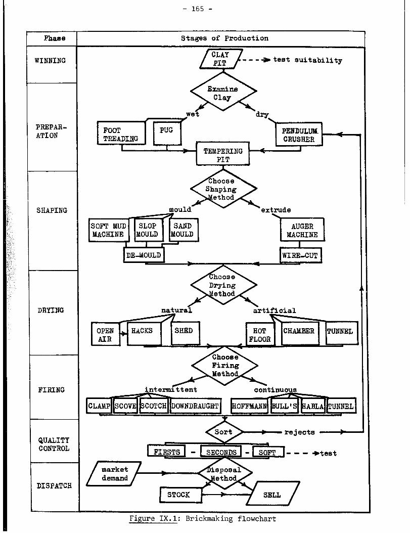
- 165 -
---*teat suitability
rejects -
- - - *teat
Figure 1X.1: Brickmaking flowchart

- 166 -
Figure 1X.2: Intermediate technology brickmaking plant

- 167 -
penetrates the shed roof. The latter is of great benefit but accounts for
approximately half of the capital cost.
Open air drying or drying in covered hacks, with good access between
stacks of bricks, requires an area of approximately 1,000 m2 for an output
of 1,000 bricks per day.
An Indian brickmaking plant (35) producing 20,000 bricks per day, and
using a washmill, settling ponds, hand moulding, open air drying and a Bull's
Trench kiln (60 m x 23 m), covers an area of at least 21,000 m2. This is at
least three times the area used in the Ghana plant per unit of output.
The Bull's Trench kiln brickworks, without a washmill but with an open air
drying area, would need twice the area of the small-scale Ghanaian plant per
unit of output.
The above examples illustrate extremes in area requirements. Intermediate
areas may be required for various types of plants.
Depending on circumstances, sufficient space should also be allocated for
offices, sanitary installations and appropriate eating accommodations.
IV. SKILL REQUIREMENTS
The owner or manager of a brickworks should have the necessary skills for
managing people as well as equipment and materials. The types of skills
necessary for brickmaking are briefly described below.
Digging clay manually or by machine may be thought of as requiring no
skill. This is, however, not the case as the careful choice of material at
the pit face, and mixing by taking vertical cuts, are essential to good
brickmaking. An appreciation of the dip and strike of the clay, and the
reasons for rejecting overburden, roots and stones, is desirable. These
skills may be taught or obtained from on-the-job training. Care and
maintenance of tools should also be part of the skills of pit workers.
Skills are also required for the preparation of the clay for brickmaking,
and in appreciating the requirements of a good clay body. Equipment should
not be abused and should receive proper maintenance.
Moulding skills are essential to the forming of good bricks. The hand
moulder and machine operator must know, for example, that the addition of
extra water to the clay, so as to make moulding or extrusion easier, will
increase shrinkage and thus the risk of cracking. The hand moulder must have
a "feel" for the clay, be able to throw it accurately into the centre of the
mould, and produce well-formed bricks at a fast rate over long periods. An
understanding of required brick quality will help an operator to maintain his
mould or die sizes within the necessary tolerances, allowing for shrinkage on
- 168 -
drying and firing. As mechanical devices are likely to wear quickly, checks
must be made occasionally, and appropriate maintenance, repair and
replacements undertaken whenever necessary.
Those responsible for drying bricks must understand the necessity for
careful handling of the latter, especially before they are leather-hard. The
operators must know when to turn bricks early in the drying stage (to allow
the underneath to dry) and when they are dry enough for firing.
Firing bricks calls for great skill in order to get a good and uniform
product. The overall dimension and setting pattern of the brick in building
up a kiln, and the spacing between individual bricks in different parts of the
kiln, are very important factors. The rate of heating and cooling must be
carefully controlled and calls for special skills in the interpretation of
various phenomena. Skills are also necessary for the control of the
temperature through adjustment of fuel-feeding and draught.
Skilled labour is needed for the sorting of bricks into various grades.
CHAPTER X
METHODOLOGICAL FRAMEWORK FOR THE ESTIMATION
OF UNIT PRODUCTION COSTS
This chapter is intended to assist practising brickmakers wishing to
improve their plant and entrepreneurs envisaging to engage in brickmaking by
providing them with a methodological framework for the evaluation of
alternative brickmaking techniques. Staff of financial institutions,
businessmen and government officers may have their own evaluation
methodologies, but could still find the following methodological framework
useful, especially if they are unfamiliar with brickmaking.
I. THE METHODOLOGICAL FRAMEWORK
The methodological framework consists of two main parts:
(i) the determination of the quantities of various inputs used in
the brickmaking process (Step 1 to 5);
(ii)the estimation of the cost for each input, and that of the unit
production cost (Step 6 to 12).
These steps are briefly described below. Producers who wish to identify
the most appropriate technique should repeat these steps for each technology
which may yield the required output.
Step 1: Determination of the number of bricks to be produced each year. This
number is a function of market demand, availability of investment funds, the
adopted production technique, etc. Chapter IX provides some guidelines for
determining the scale of production.
?tep 2: Estimation of the quantities of the various materials inputs for the
adopted scale of production. The main materials are:
- 170 -
- brickmaking clay
- sand, or an equivalent material (e.g. grog)
- water
- fuel
Guidelines for determining the quantities of each material are given in
Chapter IX.
Step 3: Compilation of a list of required equipment, including spare parts and
servicing equipment. The list should also include transport equipment
whenever necessary as well as testing equipment. Both locally made and
imported equipment should be included. Chapters II to VII provide guidelines
for the compilation of the above list.
Step 4: Labour requirements. The productivity of the labour force may be
significantly different from one .country to another. Estimates of labour
productivity are given in Chapter IX. These estimates may need to be adjusted
for part-time workers. The number of shifts per day, working days per week,
and working weeks per year should also be specified, taking into consideration
the possible closing down of the plant during the peak agricultural seasons.
The number and skills of workers may be established on the basis of the above
information.
Step 5: The local infrastructure required must be determined. It may include:
- land for exploitation of the quarry;
- land for access and buildings;
- land for drying grounds and kilns if not within the buildings;
- land for storage of raw materials and of product;
- buildings required, such as covered areas for making, drying or firing;
offices; and other amenities.
Chapter IX provide guidelines for the estimation of the area of each of
the above items.
Step 6: Working capital. Apart from purchase of land and equipment, it is
necessary to have sufficient initial financial resources to enable the
purchase of raw materials, including fuel. Working capital will also be
required for the payment of wages during an initial period, and for the
building up of a stock of bricks for sale.
It is recommended that sufficient working capital be available for two
months' materials and fuel, and one month's salaries. If difficulties are
anticipated in obtaining supplies of any particular commodity, it may be
necessary to hold a stock sufficient for more than two months' production.

- 171 -
7: Step Equipment and buildings annual depreciation costs. Whatever type of
equipment is used, it will have a limited life. An estimate must thus be made
of the annual depreciation costs for separate equipment items. The
depreciation cost of buildings must also be estimated. These costs will
depend upon the initial purchase price, the life of equipment and buildings
and the prevailing interest rate. Table X.1 may be used to estimate these
depreciation costs. It gives the discount factors (F) for interest rates up
to 40 per cent and expected life periods up to 25 years. Thus, if Z is the
purchase price of the equipment or the cost of the building, the annual
depreciation cost is equal to Z/F.
Hence, the longer the useful life, the lower the annual depreciation cost,
and the higher the prevailing interest rate, the higher this cost.
The C.1.F prices of imported pieces of equipment may be obtained from
local importers or equipment suppliers (see Appendix IV). The prices of local
equipment and buildings may be obtained from local contractors and equipment
manufacturers.
Step 8 Land has an infinite life, and the pit may be restored to its original
use in some instances. ThUS, the annual cost of land may be assumed to be
equal to the annual rent of equivalent land. Alternatively, if land is owned
by the brickmaker, a hypothetical annual rental rate should be used when
estimating the annual land cost.
Step 9: The annual cost of consumable items identified in Step 2 must be
calculated. Clay, sand and water are often extremely cheap commodities. The
only significant part of their cost, in comparison with that of fuel, is that
incurred in extracting and transporting them. Thus, the cost of sand and clay
is often included in the cost of labour, land rental rate and equipment
depreciation costs. Fuel costs are of major importance and must be determined
locally by examining current market prices.
Step 10: The cost of labour varies greatly from one country to another. They
must thus be calculated on the basis of local wage rates. The labour
requirements are those identified in Step 4.
Step 11: Working capital raised for the project will require an allowance in
the annual costs for interest payments to be made on that capital.
- 172 -
Step 12: The total annual cost consists of the sum of the separate annual
costs itemised in Steps 7 to 11.
Total annual cost =
Depreciation costs of equipment and buildings +
Annual land rental cost +
Annual labour costs +
Annual fuel costs +
Annual costs of sand and clay (if the latter are purchased
rather than won on land belonging (or rented) by the producer) +
Annual cost of water (if the latter is purchased rather than
pumped from a river or well within the production unit) +
Annual cost of electricity (if used) +
Annual interest payments on working capital.
The unit production cost of bricks is Lhen equal to:
Total annual costtAnnua1 output.
The use of the above methodological framework is illustrated in the
following example.
II. APPLICATION OF-THE METHODOLOGICAL FRAMEWORK
The framework is used to estimate the unit cost of bricks produced by a
small-scale brickmaking unit typical of those covered by this memorandum.
Production takes place six days per week all year long. The production
technique is similar to that described in Section IV.1 of Chapter I.
1 Step : Annual production of bricks: 624,000 (approximately
2,000 bricks/day)
Step 2 : Annual requirements of clay, sand, water and wood fuel;
Clay : 624 x 2 m3 = 1,248 m3
Sand: 20 per cent of clay input = 250 m3
Water ; 500 1 per 1,000 bricks = 312,000 1
Wood fuel: 1 tonne per 1,000 bricks; = 624 tonnes

- 173 -
Step 3 : List of equipment:
Winning : 3 wheelbarrows, picks, shovels
Preparation: - flat concrete area
- 2 table moulds (actual mould boxes imported;
tables manufactured locally)
Drving: Mobile rack to hold 4,000 bricks
Spares: 10 per cent of cost of equipment.
4 Step : Labour requirements:
Supervision : 1 manager
1 foreman
Winning: 2 unskilled workers
Preparing: 3 unskilled workers
Shaping: 2 skilled workers
Kiln building and 3 skilled workers (three shifts occasionally
firing: worked)
1 unskilled worker
Carrying, etc.: 1 unskilled worker
Step 5 : Land and building requirements
Land for quarry, dug 2 m deep for 25 years 1.6 ha
Land for access and buildings (including drying) 0.3 ha
Kiln area 0.2 ha
Land for storage of product 0.1 ha
Total land requirement 2.2 ha
Buildings:
covered area 20 x 20 m 400 m*
office 3x 3m 9 m2
staff amenities 4 x 3 m 12 In2
Step 6 : Working capital
Working capital to cover cost of materials for 2 months
(See step 2) and salaries for 1 month
Clay : 208 m3
Sand : 42 m3
Water ; 52,000 1
Wood fuel : 104 t
One manager: 1 month
One foreman : 1 month
Five skilled workers : 5 months
Seven unskilled workers :7 months
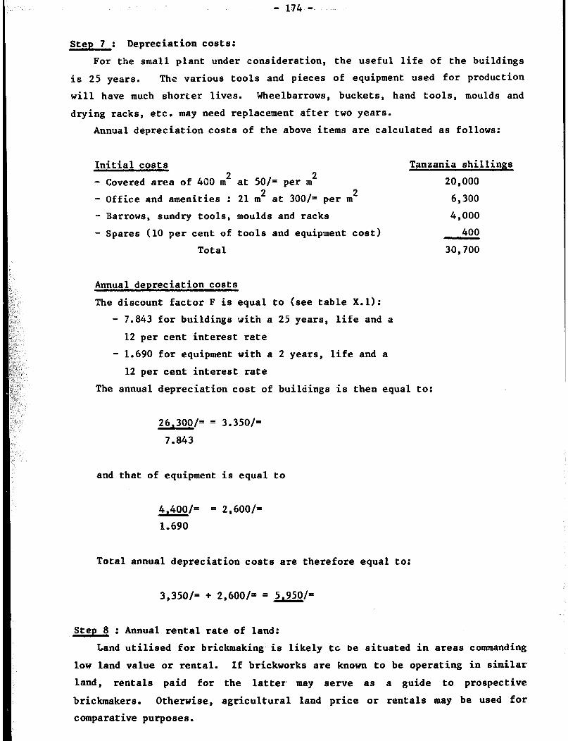
- 174 -
Step 7-: Depreciation costs:
For the small plant under consideration, the useful life of the buildings
is 25 years. The various tools and pieces of equipment used for production
will have much shorter lives. Wheelbarrows, buckets, hand tools, moulds and
drying racks, etc. may need replacement after two years.
Annual depreciation costs of the above items are calculated as follows:
Initial costs n n
- Covered area of 480 m' at 50/= per mL
- Office and amenities : 21 m2 at 300/= per m2
- Barrows, sundry tools, moulds and racks
- Spares (10 per cent of tools and equipment cost)
Total
Tanzania shillings
Annual depreciation costs
The discount factor F is equal to (see table X.1):
- 7.843 for buildings with a 25 years, life and a
12 per cent interest rate
- 1.690 for equipment with a 2 years, life and a
12 per cent interest rate
The annual depreciation cost of buildings is then e.qual to:
26,300/= = 3.350/=
7.843
and that of equipment is equal to
4,400/= = 2,600/=
1.690
Total annual depreciation costs are therefore equal to:
3,350/= + 2,600/= = 5.950/=
Step 8 : Annual rental rate of land:
20,000
6,300
4,000
400
30,700
Land utilised for brickmaking is likely tc be situated in areas commanding
low land value or rental. If brickworks are known to be operating in similar
land, rentals paid for the latter may serve as a guide to prospective
brickmakers. Otherwise, agricultural land price or rentals may be used for
comparative purposes.

- 175 -
The annual rental rate in this example is assumed to be 500 T. Shillings.
Step 9 : Annual cost of materials:
- clay 1,248 m3 at 0.72/m3
- sand 250 m3 at 0.12/m3
- water 320 m3 at 0.385/m3
- wood fuel 624 tonnes at 60/tonne
Total annual cost of materials
Step 10: Annual labour costs:
1 manager at 450/= per month
1 foreman at 400/= per month
5 skilled workers at 250/z per month each
7 unskilled workers at 200/= per month each
Total annual labour cost
Step 11 : Interest payments on working capital:
Tanzania Shillings
= 90
= 30
= 120
= 37,440
= 37,680
Tanzania Shillings
= 5,400
I 4,800
= 15,000
= 16,800
= 42,000
The cost of materials and labour listed in step 6 is equal to 9,780/x,
given the unit prices indicated in steps 9 and 10.
The annual interest payments are therefore equal to:
9,780/= X .12 = 1,170 Tanzania Shillings
Step 12 : Total unit production cost:
The total annual production cost is equal to:
5,950/= + 500/= + 37,680/= + 42,000/= + 1,170/=
Shillings
= 87,300 Tanzania
The unit production cost of bricks is then equal to;
87,300/= t 624,000/= = 0.14/= (14 cents)
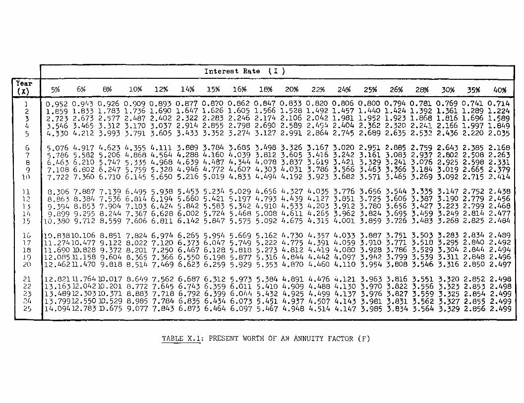
Interest Rate (I ) c,
Year 5% 6% 8% 10% 12% 14% 15% 16% 18% 20% 22% 24% 25% 26% 28% 30% 35% 40%
G 7 8 3
10
0.952 0.943 0.926 0.909 0.893 0.877 0.870 0.862 0.847 0.833 0.820 0.806 0.800 0.794 0.781 0.769 0.741 0.714 I.659 1.833 1.783 1.736 1.690 1.647 1.626 1.605 1.566 1.528 1.492 1.457 1.440 1.424 1.392 1.361 1.289 1.224 2.723 2.673 2.577 2.487 2.402 2.322 2.283 2.246 2.174 2.106 2.042 1.981 1.952 1.923 1.868 1.816 1,696 1.589 3.546 3.465 3.312 3.170 3.037 2.914 2.855 2.798 2.690 2.589 2.45!, 2.404 2.362 2.320 2.241 2.166 1.997 1.849 4.330 4.212 3.993 3.791 3.605 3.433 3.352 3.274 3.127 2.991 2.864 2.745 2.689 2.635 2.532 2.436 2.220 2.035
5.076 4.917 4.623 4.355 4.111 3.889 3.784 3.685 3.498 3.326 3.167 3.020 2.951 2.885 2.759 2.643 2.385 2.168 5.786 5.582 5.206 4.868 4.564 4.288 4.160 4.039 3.812 3.605 3.416 3.242 3.161 3.003 2.93'7 2.802 2.508 2.263 6.463 6.210 5.747 5.335 4.968 4.639 4.407 4.344 4.078 3.837 3.619 3.421 3.329 3.241 3.076 2.925 2.598 2.331 7.108 6.002 6.247 5.759 5.328 4.946 4.772 4.607 4.303 4.031 3.786 3.566 3.463 3.366 3.184 3.019 2.665 2.379 7.722 7.360 6.710 6.145 5.650 5.216 5.019 4.833 4.494 4.192 3.923 3.682 3.571 3.465 3.269 3.092 2.715 2.414
8.306 7.887 7.139 6.495 5.938 5.453 5.234 5.029 4.656 4.327 4.035 3.776 3.656 3.544 3.335 3.147 2.752 2.438 R.e63 8.384 7.536 6.814 6.194 5.660 5.421 5.197 4.793 4.439 4.127 3.851 3,725 3.606 3.387 3.190 2.779 2.456 9.394 8.853 7.904 7.103 6.424 5.842 5.583 5.342 4.910 4.533 4.203 3.912 3.780 3.656 3.427 3.223 2.799 2.468 9.899 9.295 8.244 7.367 6.628 6.002 5.724 5.468 5.008 4.611 4.265 3.962 3.824 3.695 3.459 3.249 2.814 2.477 10.380 9.712 8.559 7.606 6.811 6.142 5.847 5.575 5.092 4.675 4.315 4.001 3.859 3.726 3.483 3.268 2.825 2.484
l'J.83810.106 8.851 7.824 6.974 6.265 5.954 5.669 5.162 4.730 4.357 4.033 3.887 3.751 3.503 3.283 2.834 2.4eg 11.27410.477 9.122 8.022 7.120 6.373 6.047 5.749 5.222 4.775 4.391 4.059 3.910 3.771 3.510 3.295 2.840 2.492 11.69Olo.828 9.372 8.201 7.250 6.467 6.128 5.810 5.273 4.812 4.419 4.080 3.928 3.786 3.529 3.304 2.844 2.494 12.08511.158 9.604 8.365 7.366 6.550 6.198 5.877 5.316 4.844 4.442 4.097 3.942 3.799 3.539 3.311 2.848 2.496 12.46211.470 9.818 8.514 7.469 6.623 6.259 5.929 5.353 4.870 4.460 4.110 3.954 3.808 3.546 3.316 2.850 2.497
12.82111.764m.017 8.649 7.562 6.687 6.312 5.973 5.384 4.891 4.476 4.121 3.963 3.816 3.551 3.320 2.852 2.498 13.16312.04211).201 8.772 7.645 6.743 6.359 6.011 5.410 4.909 4.488 4.130 3.970 3.822 3.556 3.323 2.853 2.498 i13.48912.30310.371 8.883 7.718 6.792 6.399 6.0I1'+ 5.432 4.925 4.499 4.137 3.976 3.827 3.559 3.325 2.854 2.499 13.79312.55olD.529 8.985 7.784 6.835 6.434 6.073 5.451 4.937 4.507 4.143 3.981 3.831 3.562 3.327 2.855 2.499 i14.094U.783 D-675 9.077 7.843 6.873 6.464 6.0% 5.467 4.948 4.514 4.147 3.985 30834 3.564 3.329 2.856 2.499
TABLE X.1: PRESENT WORTH OF AN ANNUITY FACTOR (F)

CHAPTER XI
SOCIO-ECONOMIC IMPACT OF ALTERNATIVE
BRICK MANUFACTURING TECHNIQUES
The social and economic effects of various brickmaking options should be
of particular interest to public planners, financial institutions, business
men, housing authorities and project evaluators from industrial development
agencies. The purpose of this chapter is therefore to shed light on these
various effects with a view to helping public planners identify technologies
consonant with national socio-economic objectives, and formulate appropriate
policies for the promotion of these technologies.
I. EMPLOYMENT GENERATION
Employment generation constitutes one major objective of national
development plans of developing countries. Thus, technologies which require
more labour per unit of output than other technologies should be favoured as
long as labour is used in an efficient manner. Consequently, small-scale
brickmaking techniques should be favoured - from an employment viewpoint -
over those used in large-scale turnkey factories as they do generate
substantially more employment than the latter technologies. For example, a
study of brickmaking techniques in Bogota (Colombia) shows that large-scale
brick manufactufing plants produce 83 per cent of the national brick
production although they use only one-third of the total labour force in the
brick industry. In other words, small-scale units, using relatively
labour-intensive techniques, require approximately ten times more labour than
large-scale plants per unit of production (76). Another study carried out in
Colombia (43) shows that the labour-capital ratio in small-scale brickmaking
units is over 100 times greater than that for large-scale manufacturing plants.
Table XI.1 provides estimates of labour inputs per 10 million bricks for
various scales of production and techniques. It may be seen that the
small-scale plants require between 20 and 25 times more labour than the highly
automated plants for the same output.

- 178 -
Table XI.1
Scales of production and labour generation
Description of brickmaking
methods
Production rate of Labour per
one plant 10 million bricks per
(bricks per day) year
Small-scale, traditional
manual processes
Small-scale, intermediate
technology
Soft-mud machine, otherwise
manua 1
Moderately mechanised
Highly automated
2 000 160
2 000 200
14 000 76
64 000 20
180 000 8
II. TOTAL INVESTMENT COSTS AND
FOREIGN EXCHANGE SAVINGS
The import of expensive equipment with subsequent need for spare parts and
services can be a burden on a country’s foreign exchange reserves. The choice
of small-scale techniques and the use of locally manufactured equipment, which
can be repaired by local craftsmen, may thus partly alleviate the need for
imports and scarce foreign exchange.
A large number of developing countries also suffer from shortages of local
capital funds as exemplified by the high interest rates prevailing in these
countries. Consequently, technologies which minimise the use of capital
investments should be favoured.
Table XI.2 shows that, from a foreign exchange and capital investment
viewpoint, small-scale brickmaking technologies are, by far, much more
appropriate than large-scale, automated plants, Thus, capital investments in
large-scale plants are six to 100 times larger than those for small-scale
plants, Similarly, the import component of these investments is five to 15
times larger for the automated plants than for small-scale units.

- 179 -
Table XI.2
Capital costs and foreign exchange inputs
Description of Total cost for Proportion
brickmaking 10 million of costs
processes bricks per year (per cent)
('000 us$)
Import Local
Small-scale,
traditional
manual process 34 5 95
Small-scale
intermediate
technology 578 15 85
Mechanical plant
with Hoffman
kiln 3,880 75 25
77 Source:
III. UNIT PRODUCTION COST
A major component of the cost of a house in developing countries is that
of building materials. This is particularly the case for low-cost housing or
various self-help schemes. It is therefore important to promote the
production of low-cost building materials in order to facilitate home
ownership by lowincome groups and to reduce public investments by housing
authorities. In the case of bricks, production techniques and scales of
production which minimise unit production costs should therefore be favoured.
Although reliable estimates of these costs are not available, recent studies
(78) tend to indicate that small-scale plants, using intermediate
technologies, produce bricks at a lower cost than large-scale,

- 180 -
capital-intensive plants. Results of these studies are summarised in table
X1.3. It may be seen that the unit price of bricks produced in small-scale
plants is two to three times lower than that of bricks produced in large-scale
plants.
Table XI&
Unit production costs
Classif ication of
brickmaking process
Unit production cost (US cents per brick)
Medium wage regime Low wage regime
Capital-intensive, all year round 6.5 6.2
“Least-cost”, all year round 3.1 2.3
“Leas t-co8 t”, seasonal working only 2.9 2.0
Source: 78
IV. RURAL INDUSTRIALISATION
It is desirable to set up industries in rural areas, to counterbalance the
faster growth rate of urban areas (2). TInese rural industries, however, must
be of a size appropriate to the local markets and to the social needs of the
people. It should particularly be noted that the higher the degree of
automation (or of mechanisat ion) the higher the required professional
qualifications (7). Consequently , the chosen level of technology should be
such as to ensure that any maintenance or repair can be carried out on site.
Small-scale plants, which can operate without electricity, are also
particularly suitable for rural areas.
It is also essential that the adopted technology be consonant with the
qualification level of the local labour force. Some aspects of skill
requirements for brickmaking have been discussed in Section IV of Chapter IX.
These requirements do not constitute a major constraint to the establishment
of rural brickmaking units, especially if equipment is locally produced and
repaired. Furthermore, small-scale production techniques should be flexible
enough so that production may be increased according to market requirements
(30). The brickmaking plants may also have to operate on a seasonal basis
- iai -
(according to weather conditions and the availability of workers during peak
agricultural seasons), a condition which overrules the adoption of
large-scale, capital-intensive plants in rural areas.
V. MULTIPLIER EFFECTS
Alternative production techniques will have different multiplier effects
on the national economy (i.e. backward and forward linkages) depending on the
scale of production and the origin of equipment and materials. From a
socio-economic viewpoint, technologies associated with the largest multiplier
effects should, all other things being equal, be favoured over those with
limited effects.
Small-scale, relatively labour-intensive brickmaking technologies are
generally associated with larger multiplier effects than large-scale,
capital-intensive technologies for the following reasons. Firstly, most, if
not all, the equipment (e.g. table moulds, mixing equipment) may be
manufactured locally instead of being imported (see section II). Production of
such equipment shou Id thus generate additional employment and incomes.
Second ly , small-scale plants use local fuel (e.g. wood, agricultural wastes)
while large-scale plants often rely on oil. The gathering and processing of
fuel wood or other local materials will thus generate additional employment.
Finally, the marketing and transport of bricks produced by small-scale units
should also generate more employment than those of the output of large-scale
plants. Altogether, employment generated through multiplier effects will
further expand that.generated through the production of bricks.
VI. ENERGY REQUIREMENTS
Fuel requirements of various types of kilns have already been considered
in Chapter VII. The apparent higher fuel efficiency of large kilns must be
weighed against the fact that large plants operate with a considerable amount
of energy-consuming equipment. For example, a large plant producing 10
million bricks per year may require 300 kWh electricity supply for the running
of the equipment ( 7). Furthermore, transportation costs are likely to be
higher in large-scale plants than in small-scale plants. Thus, the low fuel
efficiency of small-scale kilns is partly offset by the higher energy inputs
for equipment used in large-scale plants. However, as energy requirements are
partly a function of the efficiency of kiln-operating procedures, it is
difficult to compare the relative fuel efficiency of small and large
production units.

- 182 -
VII. CONCLUSION
Small-scale production of bricks is generally preferable to large-scale
production under the following circumstances: where low wage regimes exist;
where foreign exchange is in short supply; where no well-developed industrial
base exists; where infrastructure and technical skills are insufficient; and
where the market is small or widespread,
Labour-intensive brickmaking techniques are often considered the most
appropriate techniques under conditions prevailing in developing countries.
However, recent studies (78) show that this may not always be the case if the
factors mentioned above are not present. Thus, project evaluators should
properly consider all available alternatives prior to promoting one technology
or another. The evaluation of alternative technologies should take into
consideration the fact that small-scale production generates more employment
than large-scale production while minimising capital investments and foreign
exchange costs.

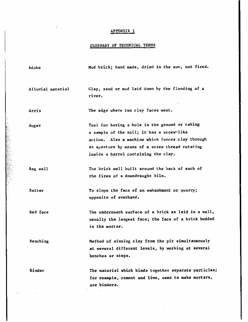
Bag wall
Adobe
Alluvial material
Arris
Auger
Batter
Bed face
Benching
Binder
APPENDIX I
GLOSSARY OF TECHNICAL TERMS
Mud brick; hand made, dried in the sun, not fired.
Clay, sand or mud laid down by the flooding of a
river.
The edge where two clay faces meet.
Tool for boring a hole in the ground or taking
a sample of the soil; it has a screrlike
action. Also a machine which forces clay through
an aperture by means of a screw thread rotating
inside a barrel containing the clay.
The brick wall built around the back of each of
the fires of a downdraught kiln.
To slope the face of an embankment or quarry;
opposite of overhand.
The underneath surface of a brick as laid in a wall,
usually the largest face; the face of a brick bedded
in the mortar.
Method of winning clay from the pit simultaneously
at several different levels, by working at several
benches or steps.
The material which binds together separate particles;
for example, cement and lime, used to make mortars,
are binders.
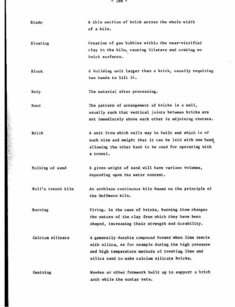
Blade
Bloating
Block
Body The material after processing.
Bond The pattern of arrangement of bricks in a wall,
usually such that vertical joints between bricks are
not immediately above each other in adjoining courses.
A thin section of brick across the whole width
of a kiln.
Creation of gas bubbles within the near-vitrified
clay in the kiln, causing blisters and craking on
brick surfaces.
A building unit larger than a brick, usually requiring
two hands to lift it.
Brick A unit from which walls may be built and which is of
such size and weight that it can be laid with one hand,
allowing the other hand to be used for operating with
a trowel.
Bulking of sand A given weight of sand will have various volumes,
depending upon the water content.
Bull’s trench kiln An archless continuous kiln based on the principle of
the Hoffmann kiln.
Burning
Calcium silicate
Centring
Firing. In the case of bricks, burning them changes
the nature of the clay from which they have been
shaped, increasing their strength and durability.
A generally durable compound formed when lime reacts
with silica, as for example during the high pressure
and high temperature methods of treating lime and
silica sand to make calcium silicate bricks.
Wooden or other fonnwork built up tc support a brick
arch while the mortar sets.

- 187 -
Clamp
Continuous kiln
Coppicing
Course
Cuckhold
Cuckle
Dip
Docking
Downdraught kiln
Ettringite
Large piie'of green bricks with fuel between those
in the bottom courses, which is set on fire to burn
the bricks. Sometimes,this term is also used to
describe a similar pile but with the fuel placed
in tunnels through the lower courses of the pile.
A kiln in which the fire is always burning, bricks
being warmed, fired, and cooled simulatenously in
different parts of the kiln.
The annual cutting of wood from trees,which therefore
do not grow to full size,yet continue to provide
useful materials such as fuel.
A horizontal layer of bricks.
A concave-bladed spade for cutting off lumps of
prepared clay.
A curved metal strip with two handles for cutting
off a pice of clay from a large lump.
The slope of a clay deposit comparxd with the
horinzontal.
Immersing fired bricks in water for a short while
so that a thin outer skin is thoroughly wetted.
Claimed by several authorities to reduce the incidence
of lime blowing.
A kiln in which hot gases pass down between the bricks
which are being fired.
A compound formed from sulphates and calcium
aluminate; if it is formed after the mortar between
the bricks is well set, it may cause softening and
expansion of the mortar joints.

Eye
Fair-faced brickwork Brick walling of an acceptable stanlard of appearance
and quality, without rendering or plastering.
Fat soil Highly plastic soil;- usually a clay rich soil
Tgith high dryir,g shrinkage.
Firing
Flash
Flash wall
Flux
Frog
Ghol
Green brick
Grog
- 188 -
The point near the base of a clamp where the fire
is first lit.
Heating in a kiln to partially vitrify (see burning).
A silver of clay on the arris of a brick, formed in
the crack or air inlet in the mould.
A long wall behind the fires on one side of a down-
draught kiln, serving to deflect the hot gases upward.
A mineral in the clay which reduces the temperature
required to obtain vitrification.
Indentation in one or sometimes both of the bed faces
of a brick. A frog cannot be put into an extruded,
wirecut brick, but is easily formed in moulded or
pressed bricks.
Clay washing tank (Indian).
Brick formed into shape but not yet fired.
Fired clay, often reject bricks, crushed to a fine
size, for addition to the clay body. Such material
reduces shrinkage and opens the body.
Habla kiln An archless zigzag continuous kiln, based on the
Hoffmann kiln.
Hard fired bricks Bricks fired to a relatively high temperature,
producing a moderate amount of vitrification
and consequent good strength and durability.

--
- 189 -
Header The small end of a brick showing in the face of
brickwork.
Heat work The combination of temperature and time and its
effect on ceramic reactions.
Hoffmann kiln A brick-arched continuous kiln, circular or
elliptical, in which waste heat is used to
preheat both the combustion air and the bricks, so
increasing fuel efficiency.
Hydraulic lime
Igneous rocks
Intermittent kiln
Lean soil
A lime which will set under water. This is due
to cetain siliceous impurities which react with
the lime itself. Non-hydraulic limes harden only
by carbonation caused by carbon dioxide in the air.
Rocks of volcanic origin; rocks which were molten
at one time.
A kiln in which the fire is allowed to die out
and the bricks to cool after they have been
fired. The kiln must be emptied, refilled and
a new fire started for each load of bricks.
Low plasticity soil, usually due to lack of the
finer sizes of clay fractions. In contrast to fat
soil.
Leather-hard bricks Bricks which have partly dried so that they can be
picked up without distorting them.
Loam Sandy clay often suitable for shaping into bricks,
and having a low drying shrinkage.
Marl Natural mixture of clay and chalk.

__ .
- 190 -
Open the clay body To increase the permeability to gases of a ceramic
body.
0ve:burden The material lying on top of a nattizal deposit of
brick clay.
Oxidising
PCE Abbreviation for pyrometric cone equivalent.
Perpend s The visible vertical joints between bricks
in a wall.
Plastic material
Plasticity
Profile
Puddle
Pyrometric cone
Reducing
Refractory
Render
Ring
Conditions of sueEioundings in which oxygen is freely
avai? ;-:‘uLe.
Material able to be deformed by moderate pressure
and retaining the deformed shape when the pressure
is removed.
Possessing the property of being plastic.
A section taken through the various strata of a soil.
To mix up dry soil or lime with water, usually
manua 1 ly .
A small clay-based cone which will squat after
undergoing a certain amount of heat work.
Conditions of surroundings in which little or no
oxygen is available.
Heat-resisting,
To cover an exterior wall surface with a cement-lime
based mix.
The high-pitched metallic sound obtained when two
well-fired bricks are struck against each other.

- 191 -
Kunne r Person who carries slopmoulded bricks in mould to
the drying ground.
Stove To cover over with mud. The name of the stove kiln
originates from the practice of scoving the outside
bricks in order to stop the heat from escaping from
the pile of bricks being fired.
Sesquioxides The oxides of aluminium and iron.
Shale Soft laminated slate-like rock, harder than most
clays.
Short material Lacking plasticity,’ lean.
Siliceous Having a high proportion of silica.
Slake To fall apart when immersed in water.
Slip A thin slurry of clay in water; very wet and runny
mix of clay.
Soak stage Period during which bricks are kept at a fixed
elevated temperature in a kiln. Also immersion
of bricks in water.
Soft-f ired bricks Bricks heated in a kiln to a relatively low
temperature; bricks so treated do not exhibit optimal
physical properties.
Solar gain Heat obtained from the sun.
Sour Leave.clay in contact with water for a long period.
Spall. Flake away from the surface.
Specific surface area The total area of either the many fine particles or
the many fine pores in a solid within a standard
weight of the material.

- 192 -
Squat The deformation of a clay near its vitrification
point, especially the deformation of a pyrometric
cone.
Strain
Strata The various layers in a sedimentary deposit.
. .
Stress A measure of the force applied to produce strain
in an object
Stretcher
Strike
Striker
Sump
Surkhi
Temper
Terracing
Thermal capacity
A measure of the change in size compared to the
original size.
The long face of a brick (not the bed face) showing
in a wall.
The direction in a clay deposit in which the clay
is at the same depth. Also a piece of wood for
pushing off excess clay in slop moulding.
Piece of wood for pushing off excess clay in slop
mould ing .
A depression into which water may be drained off,
or wastes deposited.
Soft-f ired clay, ground up, for mixing with lime
to make mortar (Indian).
Leave in wet condition, often overnight or longer
to make clay more workable and easier to mould.
Benching.
A measure of the quantity of heat which an object
can hold; high values in building components reduce
temperature extremes within the building.
Tunne 1 ki In Closed kiln or dryer through which the bricks are
carried on wheeled cars.
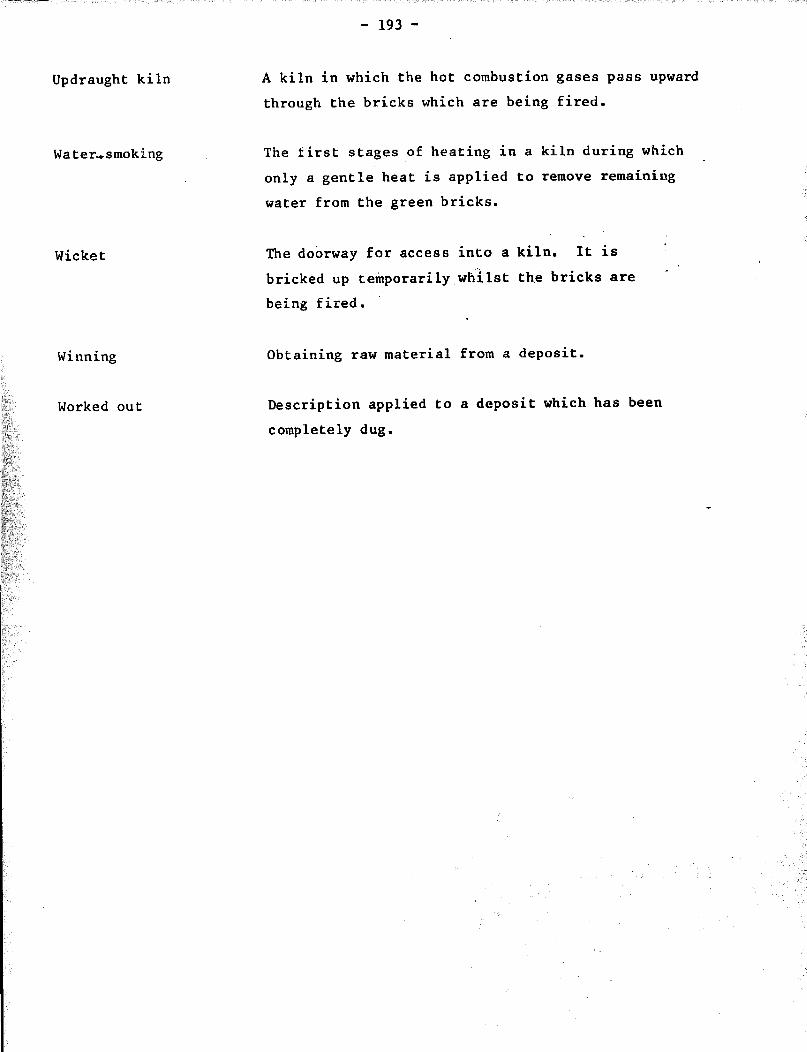
- 193 -
Updraught kiln A kiln in which the hot combustion gases pass upward
through the bricks which are being fired.
Water,smoklng The first stages of heating in a kiln during wRich
only a gentle heat is applied to remove remaining
water from the green bricks.
Wicket
Winning Obtaining raw material from a deposit.
Worked out Description applied to a deposit which has been
completely dug.
The doorway for access into a kiln. It is '
bricked up tetiporarily ,wc"ilst th.e bricks are ' '
being fired.
APPENDIX II
BIBLIOGRAPHICAL REFERENCES
(1) Habitat: Global review of housing, conference on Human Settlements, Dot. No. A/CONF/70/Al (Vancouver, 1976).
(2) United Nations Commission on Human Settlements: Report on Fifth Session, Habitat News (Nairobi), Vol. 4, No. 2, Aug.-Sep. 1982, p. 10.
(3) Sikander, A.S.; Quadeer, M.A. : "Squatter settlements - A functional view", in Vol. 2 of the Proceedings of a conference of the International Association for Housing Science held in Dharan in 1978, (New York, Wiley and Sons, 19821, pp. 437-446.
(4) UNIDO; Development of clay building materials industries in developing countries, report of seminar held in Copenhagen, Dot. No. ID/28 (Vienna, 1968).
(5) UNIDO: Establishment of the brick and tile industry, Dot. No. ID/15 (Vienna, 1969).
(6) UNIDO: Brickmaking plant. Industry profile. Development and transfer of technology series No. 10 (New York, 1978).
(7) Bender, W.: The planning of brickworks (Plymouth, Macdonald and Evans, 1978).
(8) Searle, A.B.: Modern brickmaking (London, Ernest Be'nn, 1956).
(9) UNIDO: Clay building materials industries in Africa, report of a workshop held in Tunis in 1970 (Vienna, 1971).
(10) Parry, J.P.M.: Brickmaking in developing countries (Garston, Watford, British Research Institute, 1979).
(11) Lunt, M.G.: Stabilised soil blocks for buildings. Overseas Building Note No. 184 (Garston, British Research Institute, 1980).
(12) Smith, R.G. : "Small-scale production of gypsum plaster for building in the Cape Verde Islands" in Appropriate Technolo_gll (London, Intermediate Technology Development Group) 1982, Vol. 8, No. 4, pp.4-6.
(13) l Long-term unrestrained expansion of test bricks in Transactions of the British Ceramic Society (London), 1973, Vol. 72, No. 1, pp. l-5.,.
(14) British Research Institute: (Garston, Watford), 1980, p. 237.
"Materials for concrete" in Digest No. 237
(15) : "Repairing brickworks" in Digest No. 200 (Garston), 1981, pa 2.
(16) Schumacher, E.F.: Small is beautiful: A study of economics as if people mattered (London, Blond and Briggs, 1973).
(17) Grimshaw, R.W.: The chemistry and physics of clay, (London, Ernest Benn, 1971).
- 196 -
(18) British Standards Institution: Methods of test for soils for engineering Purposes Dot. No. BS1377 (London, 1975),
(19) Doat, P.; Hay, A.; Houben, H.; Matuk, S.; and Vitoux, F.; Construire en terre (Paris, Collection An-Architecture, 1979).
(20) Stulz, R.: _Appropriate building materials. Publication No. 12 (St. Gall, Swiss Centre for Appropriate Technology 1981).
(21) Department of Housing and Urban Development, Office of International Affairs: Handbook for building houses of earth, (Washington, DC, n.d.).
(22) Knizek, I.: Brickmaking plant. Industry profile. Development and transfer of technology series No. 10 (New York, UNIDO, 1978).
(23) Butterworth, B.; Methods of assessing the suitability of clays for brickmaking (London, Claycraft, 1947).
(24) Clews, F.H.: Heavy clay technology, (Stoke-on-Trent, British Ceramic Research Association,'l969).
(25) West, H.W.H.: Production technology - Winning, preparation and shaping of , Dot, No. ID/WG/81/4 (New York, UNIDO, 1970).
(26) Smith, R.G.: BrickmakiZg_by Malagasy artisans and the establishment of a pilot centre (Geneva, ILO, 1980).
(27) Sedalia, B.M.: Structural clay industry (Bandung, United Nations Regional Housing Centre, 1976).
(28) Svare, T.I.: Better burnt bricks, technical pamphlet No. 1 (Dar-es-Salaam, National Housing and Building Research Unit, 1971).
(29) Harley, G.T.: "A study of shovelling" in Transactions of the British Ceramics Society (Stoke-on-Trent), 1932, Vol. 31, No. 1, pp. l-35.
(30) Chatterjee, A.K.: "Clay preparation and product manufacture", in Small-Scale Building and Road Research News (Khumasi), 1977, Vol. 2, No. 2.
(31) Srinivasan S. and Jain L.C.: “Lime bursting in bricks" in Digest No. 113 (Roorke, India, Central Building Research Institute, 1975).
(32) Amonoo-Neizer, K.: Asokwa brick project , Special Report No. SR l/73 (Kumasi, Ghana, Building and Road Research Institute, 1973).
(33) Woodforde, J.: Bricks to build a house (London, Routledge and Kegan Paul, 1976).
(34) Hammond, M. : Bricks and brickmaking, (Princes Risborough, United Kingdom, Shirs Publications, 1981).
(35) Prakash, S.; Majundar, N.C.: "Manufacture of bricks of improved quality in Bhopal", in Journal of Engineers and Planners (New Delhi), 1974, Vol. 2, Nos. 8 & 9, pp. 27-30.
(36) Indian Standards Institution: Specification for burnt clay facinp bricks, Dot. No. IS 2691-1972 (New Delhi, 1972).
(37) British Standards Institution: Specification for clay bricks and blocks, Dot. No. IS No. 3921-1974 (London, 1974).

- 197 -
(38j Mcjumdar, N.C.; Wadhwa, S.S.; Hiralal, E.S.: "Manufacture of building bri:ks by a semi-mechanised process", in Transactions of the Indian Ceramics Society !New Delhi), 1969, Vol. XXVIII, No. 4, pp. 121-128.
(39) Majumdar, N.C.; Hiralal, E.S.; Handa, S.K.: An appropriate technology for mechanised production of building bricks. Procee.dings of a'national seminar on building materials - their science and techno-logy (New Delhi, 1982).
(40) Thomas, D.W.: Small-scale manufacture of burned building brick (Arlington, Virginia, Volunteers in Technical Assistance, 1977).
(41) Smith, R.G.: "Improved moulding devices for hand-made bricks", in Appropriate. Technology (London, Intermediate Technology Publications), 1981 Vol. 7, No. 4.
(42) Weller, H.O.;Campbell, A.J.: Brickmaking in East Africa (Nairobi, East African Industrial Research Board, 1945).
(43) Baily, M.A.: "Brick manufacturing in Colombia: A case study of alternative technologies", in World Development (London, Pergamon Press), 1981, pp. 201-213.
(44) Ford, R.W.: Drying, Institute of Ceramics Textbook series No. 3 (London, Maclaren, 1974).
(45) Macey, H.H. : Drying in the heavy clay industry, National Brick Advisory Council Paper No. 3 (London, Her Majesty Stationary Office, 1950).
(46) Small Industries Development Organisation: Burnt clay brickmaking, Rural Industries Guide No. 4 (Dar-es-Salaam, n.d.1.
(47) Schmidt, H.: "Measures to counteract defects in bricks during firing in Ziegelindustrie International, Issue No. 3, Mar. 1980, pp. 153-162.
(48) Noble, W.: The firing of common bricks, National Brick Advisory Council Paper No. 4 (London, Her Majesty Stationary Office, 1950).
(49) Jain, L.C.: "Effect of sodium chloride on the prevention of lime blowing" in Indian Ceramics (New Delhi), Mar. 1980, Vol. 17, No. 7, pp. 262-266.
(50) Laird, R.T.; Worcester, M.: "The inhibiting of lime blowing in bricks" in Transactions of the British Ceramic Society, 1956, Vol. 55, No. 8.
(51) Spence, R.J.S.: An investigation of the properties of rural and urban bricks, Paper No. TR9 (Lusaka, National Council for Scientific Research, 1971).
(52) Gundry, D.G.: "Brickmaking on the farm" in Rhodesia Agricultural Journal (Harare), 1951, Vol. XLVIII, NO. 4,, pp. 330-343.
(53) Hill, N.R.: "A clamp can be appropriate for the burning of bricks", in Appropriate Technology, 1980, Vol. 7, No. 1,.
(54) Majumdar, N.C.: "Firing of Bull's Trench kilns", in Indian Builder, Sep. 1957.
(55) Indian Standard Institution: Guide for the design and manufacture of brick kilns, Dot. No.IS 4805-1968 (New Delhi, 1968).

- 198 -
(56) Spence, R.J.S.: "Brick manufacture using the bull's trench kiln", in Appropriate Technology, 1975, Vol. 2, No.- 1.
(57) "New archless continuous kiln", in British Clayworker (London), May 1929.
(58) Majumdar, N.C.; Hiralal, E.S.: "High draught kiln ; its operation, control and economics", in Brick and Tiles News (Roorke, India, Central Building Research Institute), 1980, pp. 47-51.
(59) Salmang, H.: Ceramics: physical and chemical fundamentals (London, ' .
Butterworths, 1961). . .
(60) FAO: Yearbook 1981 (Rome, 1982). - * . .. ., km .- .' _ :
(61) Madibbo, A.M.; Richter, M.: Research Digest (Khartoum,
"Fired clay bricks in the Sudan", in Building National Building Research Station), 1970, No. 6,
Phase 1.
(62) Rad, P.F.: "A simple technique for determining strength of brick", in Proceedings of the North American Masonry Conference (1978) Part. 40, pp. l-10.
(63) Jain, L.C.: "Accelerated test for lime blowing", in British Clayworker, 1971, Vol. 80, No. 947, pp. 40-41.
(64) Butterworth, B.: "The frost resistance of bricks and tiles - A review", in Journal of the British Ceramic Society (Stoke-on-Trent), 1964, Vol. 1, No. 2, ppe 203-223.
(65) Spence, R.J.S.: Small-scale production of cementitious materials (London, Intermediate Technology Publications, 1980).
(66) Smith, R.G.: Rice husk ash cement (Rugby, United Kingdom, Intermediate Technology Industrial S,ervice, 1983).
(67) Central Building Research Institute; Cementitious binder from waste lime sludge and rice husk, Technical Note No. 72, (Roorke, India, 2nd edition, 1980).
(68) Spence, R.J.S.: $lternative cements in India (London, Intermediate Technology Development Group, 1976).
(69) Indian Standards Institution: Specification for lime pozzolana mixture, No. IS 4098-1967 (New Delhi, 1967).
(70) Beningfield, N.: Aspects of cement-based mortars for brickwork and blockwork concrete (London, 1980).
(71) Smith, R.G. : *sum, Proceedings of a meeting on small-scale manufacture of cementitious materials (London, Intermediate Technology Publications, 1974).
(72) British Standards Institution: Specification for masonry cement, Dot. No. BS 5224-1976 (London, 1976).
(74)Buttterworth, B. : The properties of clay building materials, Paper presented to a Ceramics Symposium (Stoke-on-Trent, British Ceramic Society, 1953).
- 199 -
(75) Macey, H.H.; Green, A.T.: The labour involved in making and firing common bricks, National Brick Advisory Council Paper No. 2 (London, HMSO, 1947).
(76) Centro National de la Construction: Diagnosis of the economic and technological State of the Colombian brickmaking industry, Dot. No. CEN lo-76 (Bogota, 1976).
(77)Parry, J.P.M.: Technical options in brick and tile production, Paper presented to an Intermediate Technology Workshop (Birmingham, 1983).
(78) Keddie, J.; Cleghorn, W.: "Least cost brickmaking", in Appropriate Technolou, 1978,. Vol. 5, No. 3, pp. 24-27.
'(79) British Research Establishment: Building research centred and similar organisations thshout the world, Overseas Building Note No.' 163 (Garston, Watford, 1978).
(80) UNIDO: Information sources on-the ceramics industry, Guide to Information Sources No. 17 (New York, 1975).
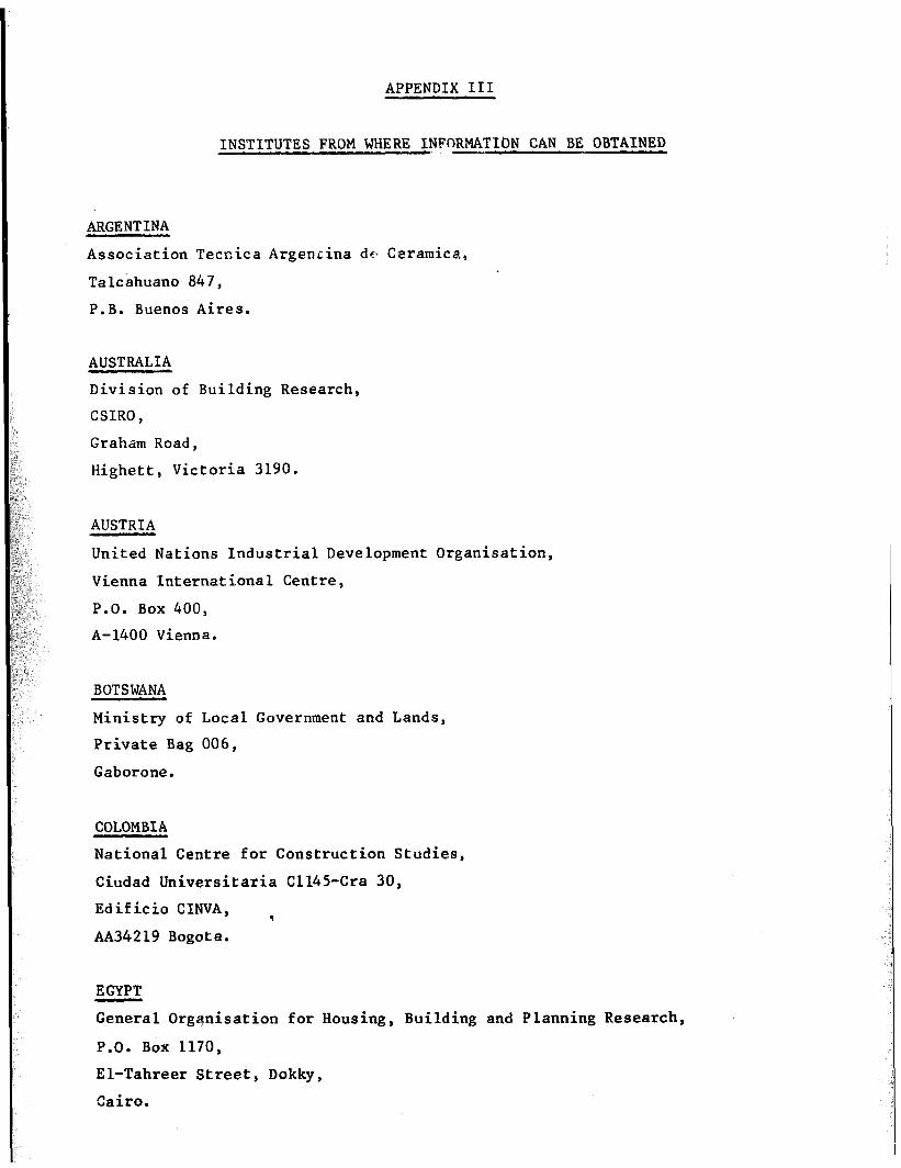
APPENDIX III
INSTITUTES FROM WHERE INFORMATICN CAN BE OBTAINED
ARGENTINA
Association Tecnica Argenrina dca Ceramica,
Talcahuano 847,
P.B. Buenos Aires.
AUSTRALIA
Division of Building Research,
CSIRO,
Graham Road,
Highett, Victoria 3190,
AUSTRIA
United Nations Industrial Development Organisation,
Vienna International Centre,
P.O. Box 400,
A-1400 Vienna.
BOTSWANA
Ministry of Local Government and Lands,
Private Bag 006,
Gaborone.
COLOMBIA
National Centre for Construction Studies,
Ciudad Universitaria C1145-Cra 30,
Edificio CINVA, .
AA34219 Bogota.
EGYPT
General Organisation for Housing, Building and Planning Research,
P.O. Box 1170,
El-Tahreer Street, Dokky,
Cairo.

- 202 -
FRANCE
Centre Technique des Tuiles et Briques,
2, avenue Hoche,
75008 Paris.
Internationai Union of Testing and Researck. XJaboratories (RILEM),
12, rue Brancion, .
75737 Paris
FEDERAL REPUBLIC OF GERMANY
Institut fiir Ziegelforschung, Essen e V, Am Zehnthof,
4300 Essen-Kray.
.GHANA Building and Road Research Institute,
University, P.O. Box 40,
Kumasi.
INDIA
Central Building Research Institute,
Roorke (Uttar Pradesh), 277672.
INDONESIA
Directorate of Building Research,
United Nations Regional Housing Centre,
P.O. Box 15,
84 Jalan Tamansari,
Bandung.
LEA9 Building Research Centre,
P.O. Box 127,
Jadiriyah, Bagdad.
,ISRAE$
Building Research Station,
Israel Institute of Technology,
Technion City, Haifa.
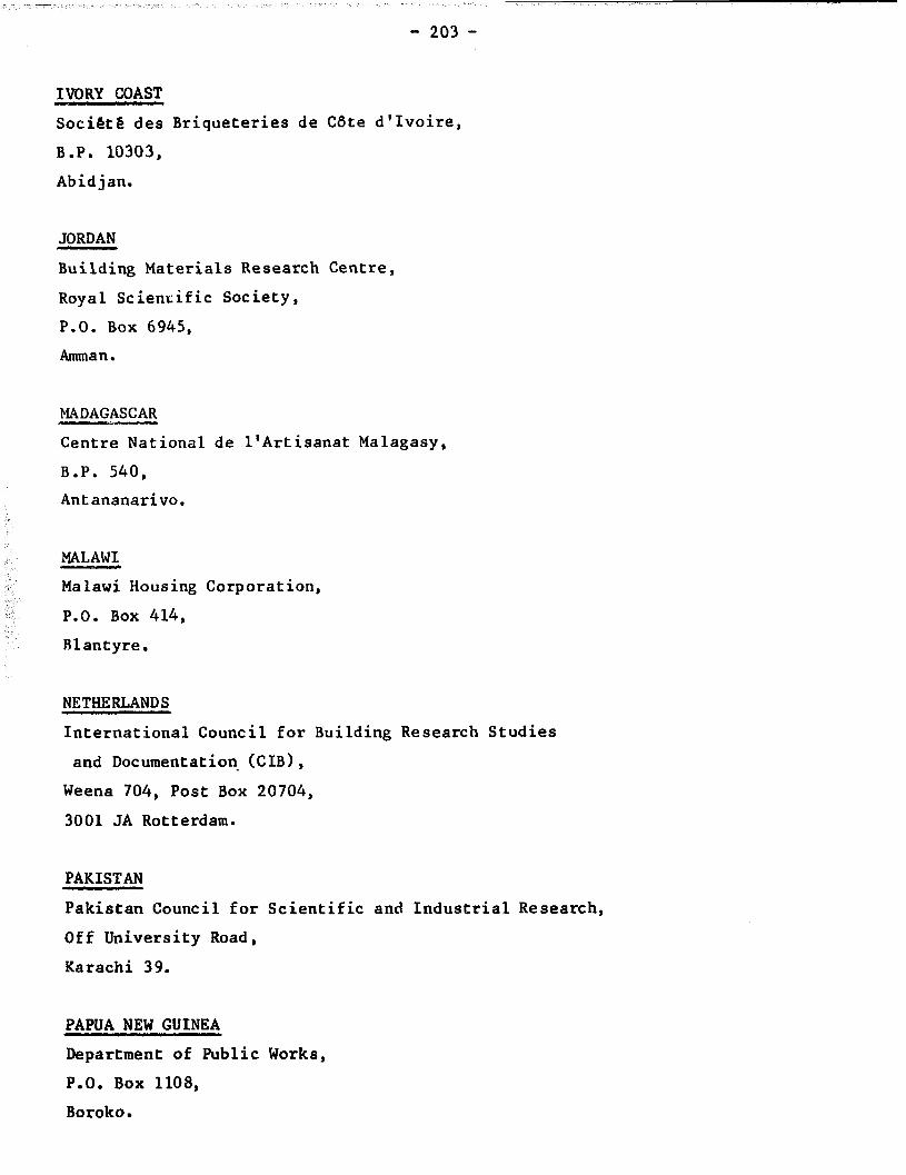
- 203 -
IVORY CCAST
Soci&& des Briqueteries de CSte d'Ivoire,
B.P. 10303,
Abidjan.
JORDAN
Building Materials Research Centre,
Royal Scientific Society,
P.O. Box 6945,
Amman.
MADAGASCAR
Centre National de l'hrtisanat Malagasy,
B.P. 540,
Antananarivo.
MALAWI,
Malawi Housing Corporation,
P.O. Box 414,
Blantyre.
NETHERLANDS
International Council for Building Research Studies
and Documentation- (CIB),
Weena 704, Post Box 20704,
3001 JA Rotterdam.
PAKISTAN
Pakistan Council for Scientific and Industrial Research,
Off University Road,
Karachi 39.
PAPUA NEW GUINEA
Department of Public Works,
P.O. Box 1108,
Boroko.
- 204 -
PHILIPPINES
Ceramic Association of the Philippines,
P.O. Box 499,
Makati, Rizal.
$TDAN
Building and Road Research Institute,
University of Khartoum,
P.O. Box 35,
Khartoum
SWITZERLAND
Technology and Employment Branch,
International Labour Office,
CH-1211 Geneva 22.
International Standard Organisation,
1, rue de VarembG,
CH-1211 Geneva
TANZANIA
Small Industries Development Organisation,
P.o. Box 2476,
Dar-es-Salaam.
THAILAND
Applied Scientific Research Corporation of Thailand
196 Phahonyothin Road,
Bankkhen,
Bangkok.
TRINIDAD
Caribbean Industrial Research Institute,
Post office box,
Tunapuna.
UNITED KINGDOM
- 205 -
British Ceramic Research Association,
Queens Road,
Penkhull,
Stoke-on-Trent ST4 7LG.
Building Research Establishment,
Bucknalls Lane,
Garston, Watford, Herts WD2 7JR.
Intermediate Technology Development Group,
9, King Street,
Covent Garden, London WC2E 8HN.
Intermediate Technology Workshop,
Corngreaves Trading Estate,
Overend Road,
Warley, West Midlands B64 7DD.
UNITED STATES
American Ceramic Society, Inc.,
4055 North High Street,
Columbus, Ohio 43214.
Volunteers in Technical Assistance,
1815 N. Lynn Street,
Suite 200,
P.O. Box 12438,
Arlington, Virginia 22209
UPPER VOLTA
Soci&e Voltai'que de Briqueterie et de Ceramique
B.P. 148,
Ouagadougou.
ZAMBIA
National Council for Scientific Research,
P.O. Box CH 158,
Chelston, Lusaka.

APPENDIX IV
LIST OF EOUIPMENT SUPPLIERS
Type of equipment
AUSTRALIA
Automet Industries Pty Ltd.,
P.O. Box 68,
88 Beattie Street,
Balmain NSW 2014,
BELGIUM
Sa Samic,
Hanswijvaart 21,
2800 Mechelen
DENMARK
Niro Atomizer A/S,
Gladsaxevej 305,
DK-2860 Soeborg
FRANCE
CERIC International,
18, rue Royale,
75008 Paris
GHANA
Agricultural Engineers,
Accra
INDIA
Raj Clay Products,
5 Mill Officers' Colony,
Ashram Road,
Navrangpura,
Ahmedabad 380009
General equipment
General equipment
1
General equipment
General equipment
Trough mixer
Semi-mechanised equipment

- 208 -
ITALY
Unimorando Consortium,
Corson Don Minzoni 182,
14100 Asti
KENYA
Christian Industrial Training Centre (CITC),
Meru Road, Pumwani
P.O. Box 729935
Nairobi
NETHERLANDS
Joh's Aberson bv.,
8120 AA, Olst
UNITED KINGDOM
Craven Fawcett Ltd.,
P.O. Box 21, Dewsbury Road,
Wakefield, Yorkshire, WF2 9BD
William Boulton Ltd,
Providence Engineering Works,
Burslem,
Stoke-on-Trent, Staffs, ST6 3BQ
Croker Ltd.,
Runnings Road,
Cheltenham, Glos.
British Ceramic Plant Manufacturers's
Association,
P.O. Box 107,
Broadstone, Dorset BH18 8LQ
W.G. Cannon,
Broadway House,
The Broadway,
London SW19
General equipment
Crusher, table mould
Soft mud
General equipment
General equipment
Pan mixer
General information service
Fans
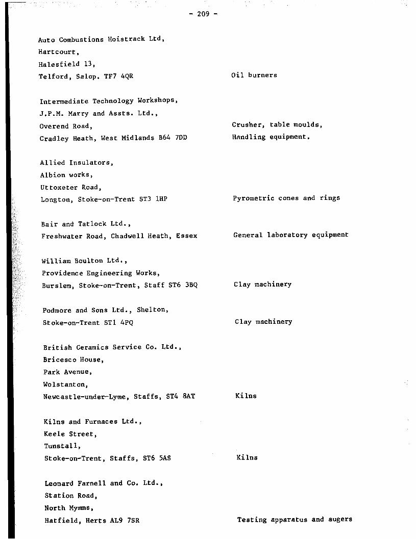
__~~ -
- 209 -
Auto Combustions Hoistrack Ltd,
Hartcourt,
Halesfield 13,
Telford, Salop. TF7 4QR
Intermediate Technology Workshops,
J.P.M. Marry and Assts. Ltd.,
Overend Road,
Cradley Heath, West Midlands B64 7DD
Allied Insulators,
Albion works,
Uttoxeter Road,
Longton, Stoke-on-Trent ST3 1HP
Bair and Tatlock Ltd.,
Freshwater Road, Chadwell Heath, Essex
William Boulton Ltd.,
Providence Engineering Works,
Burslem, Stoke-on-Trent, Staff ST6 3BQ
Podmore and Sons Ltd., Shelton,
Stoke-on-Trent ST1 4PQ
British Ceramics Service Co. Ltd.,
Bricesco House,
Park Avenue,
Wolstanton,
Newcastle-under-Lyme, Staffs, ST4 8AT
Kilns and Furnaces Ltd.,
Keele Street,
Tunstall,
Stoke-on-Trent, Staffs, ST6 5AS
Leonard Farnell and Co. Ltd.,
Station Road,
North Mymms,
Hatfield, Herts AL9 7SR
Oil burners
Crusher, table moulds,
Handling equipment.
Pyrometric cones and rings
General laboratory equipment
Clay machinery
Clay machinery
Kilns
Kilns
Testing apparatus and augers

- 210 -
UNITED STATES
Interkiln Corporation of America,
P.O. Box 2048,
Houston, Texas 77252
ZIMBABWE
World Radio Systems,
Bush House, 72-72 Cameron Street,
P.O. Box 2772,
Harare
General equipment
Crusher, table moulds

QUESTIONNAIRE
1.
2.
3.
4.
Full name ................................................................
Address ..................................................................
..................................................................
..................................................................
Profession (check the appropriate case)
Established brickmaker ................................................ /I
If yes, indicate scale of production ................................
Government official /I ..................................................
If yes, specify position .............................................
Employee of a financial institution /I ..................................
If yes, specify position ............................................
University staff member /I ..............................................
Staff member of a technology institution ............................ /I
If yes, indicate name of institution ................................
....................................................................
Staff member of a training institution /I ..............................
If yes, specify .....................................................
....................................................................
Other, qecify .......................................................
.....................................................................
From where did you get a copy of this memorandum?
Specify if obtained free or bought ...................................
.....................................................................
i

5. Did the memorandum help you achieve the following:
(Check the appropriate case)
Learn about brickmaking techniques you were not aware of
Obtain names of equipment suppliers
Estimate unit production costs for various scales
of production/technologies
Order equipment for local manufacture
Improve your current production technique
Cut down operating costs
Improve the quality of produced bricks
Decide which scale of production/technology to
adopt for a new brickmaking plant
If a Government employee, to formulate new measures
and policies for the brickmaking industry
If an employee of a financial institution, to assess
a request of a loan for the establishment of a brick-
making plant
If a trainer in a training institution, to use the
memorandum as a supplementary training material
If an international expert, to better advise counter-
parts on brickmaking technologies
6. Is the memorandum detailed enough in terms of: Yes No 1 I I
ii
- Description of technical aspects......................... I . . . . . -I I
- Names of equipment suppliers ..*.......................... . . ..a I i I I

i I I I I I I I I I I I
; I
I I I I
I
I
I
i I I
i I I
I I I I
I I I ! I I
I I I I
I I
- Costing information ...........................................
- Information on socio-economic impact ..........................
- Bibliographical information . . . . . . . . . . . . . . ..e............. . . . . .
If some of the answers are 'No' , please indicate why below or on a
separate sheet:
.."...........................................................................
. . . . . . . . . . . . . . . . . . . . . . . . . . ..*..~.......~......*...............~=....~.........
. . . . . . . . . . . . . . . . . . . . . . . . . . . . . . . . . . . . . ..*..................................*...
7. How may this memorandum be improved if a second edition is to be
published3 . . . . . . . . . . . . . . . . . . . . . . . . . . . . . . . . . . . . . . . . . . . . . . . . . . . . . . . . . . . . . . . . . . . . .
. . . . . . . . . . ..~....................................................~~...........
. . . . . . . . . . . . . . ..~..L..........................................................
8. Please send this questionnaire, duly completed to:
Technology and Employment Branch
International Labour Office
CH-1211 GENEVA 22 (Switzerland)
9. In case you need additional information on some of the issues covered by
this memorandum, the IL0 would do its best to provide the requested
information.
. . . 111
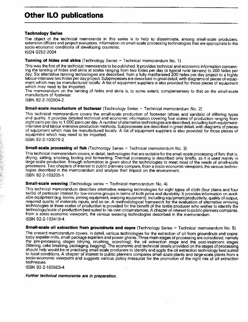
Other IL0 publications
Technology Series The object of the technical memoranda in this series is to help to disseminate, among small-scale producers, extension officers and project evaluators. information on small-scale processing technologies that are appropriate to the socioeconomic conditions of developing countries.
ISSN 0252-2004
Tanning of hides and skins (Technology Series - Technical memorandum No. 1)
This was the first of the technical memoranda to be published. It provides technical and economic information concern- ing the tanning of hides and skins at scales ranging from two hides per day (a typical rural tannery) to 200 hides per day. Six alternative tanning technologies are described, from a fully mechanised 200 hides per day project to a highly labour-intensive two hides per day project. Subprocesses are described in great detail, with diagrams of pieces of equip- ment which may be manufactured locally. A list of equipment suppliers is also provided for those pieces of equipment which may need to be imported. The memorandum on the tanning of hides and skins is, to some extent, complementary to that on the small-scale manufacture of footwear. ISBN 92-2-l 02904-2
Small-scale manufacture of footwear (Technology Series - Technical memorandum No. 2)
This technical memorandum covers the small-scale production of footwear (shoes and sandals) of differing types and quality. It provides detailed technical and economic information covering four scalesof production ranging from eight pairs per day to 1,000 pairs per day. A number of alternative technologies are described, including both equipment- intensive and labour-intensive production methods. Subprocesses are described in great detail, with diagrams of pieces of equipment which may be manufactured locally. A list of equipment suppliers is also provided for those pieces of equipment which may need to be imported. ISBN 92-2-l 03079-2
Small-scale processing of fish (Technology Series - Technical memorandum No. 3)
This technical memorandum covers, in detail, technologies that are suitable for the small-scale processing of fish: that is, drying, salting, smoking, boiling and fermenting. Thermal processing is described only briefly, as it is used mainly in large-scale production. Enough information is given about the technologies to meet most of the needs of small-scale processors. Two chapters of interest to public planners compare, from a socioeconomic viewpoint, the various techno- logies described in the memorandum and analyse their impact on the environment.
ISBN 92-2-l 032051
Small-scale weaving (Technology series - Technical memorandum No. 4)
This technical memorandum describes alternative weaving technologies for eight types of cloth (four plains and four twills) of particular interest for low-income groups in terms of both price and durability. It provides information on avail- able equipment (e.g. looms, pirning equipment, warping equipment), including equipment productivity, quality of output, required quality of materials inputs, and so on. A methodological framework for the evaluation of alternative waaving technologies at three scales of production is provided for the benefit of the textile producer who wishes to identify the technology/scale of production best suited to his own circumstances, A chapter of interest to public planners compares, from a socioeconomic viewpoint, the various weaving technologies described in the memorandum.
ISBN 92-2-l 03419-4
Small-scale oil extraction from groundnuts and copra (Technology Series - Technical memorandum No. 5)
The present memorandum covers, in detail, various technologies for the extraction of oil from groundnuts and copra: baby expeller mills, small package expellers and power ghanis. Three main stages of processing are considered, namely the ore-processing stages (drying, crushing, scorching), the oil extraction stage and the post-treatment stages (filtering. cake breaking, packaging, bagging). The economic and technical details provided on the stages of processing should help would-be or practising small-scale producers to identify and apply the oil extraction technology best suited to local conditions. A chapter of interest to public planners compares small-scale plants and large-scale plants from a socioeconomic viewpoint and suggests various policy measuras for the promotion of the right mix of oil extraction techniques.
ISBN 92-2-l 035034
Further technical memoranda are in preparation.

!t II; hoped that the Infnrmatlon contained In this memo
raildU!Tl Wil! fIelp w~ilild lx or practlslng brlckmakers to
cholxe and apply brlckm;rk.!ng ?echnlques that mlnlrnlse
productlorl costs wh:le lmprovrng the quality of the finished +
. brlcki;