small community water supply (an illustrative … community water supply (an illustrative manual)...
TRANSCRIPT
Small Community Water Supply (An Illustrative Manual)
Compiled by
Dr. S. Vigneswaran Dr. Kiran K. Bhattarai
Mr. Ram Sharma Tiwaree
Environmental Engineering Division Asian Institute of Technology
Bangkok, Thailand June, 1989
S m a l l C o m m u n i t y W a t e r " S u p p l y
C A n I 1 1 u s t r^a t ± v & M a n u a l )
Compiled by
Dr. S. Vigneswaran Dr. Kiran K. Bhattarai Mr. Ram Sharma Tiwaree
I ' ' I p.c. ^- - : - *'• r.v: : Vol, ( 0 , ^ , .•;•: " .:.-.t, '•••:•'•
HX-. G^<
/ ? / ! •
Environmental Engineering Division Asian Institute of Technology
Bangkok, Thailand June, 1989
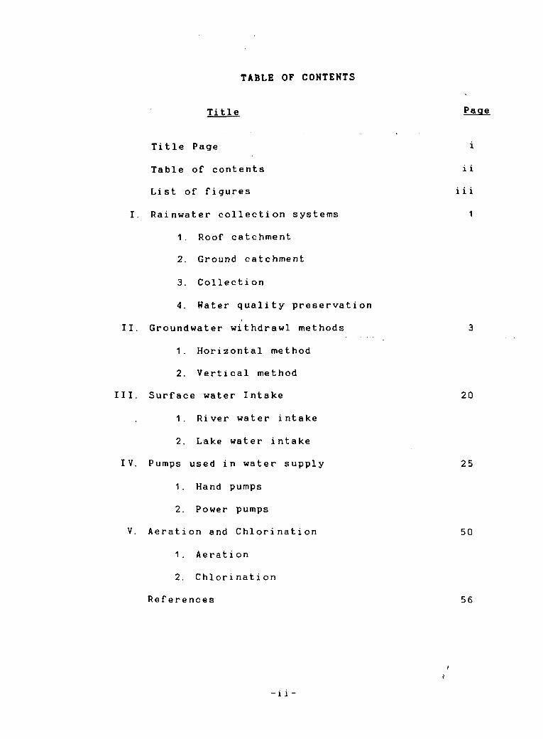
TABLE OF CONTENTS
Title
Title Page
Table of contents
List of figures
I. Rainwater collection systems
1. Roof catchment
2. Ground catchment
3. Collection
4. Water quality preservation
I. Groundwater withdrawl methods
1. Horizontal method
2. Vertical method
I. Surface water Intake
1. River water intake
2. Lake water intake
V. Pumps used i n w a t e r s u p p l y
1. Hand pumps
2. Power pumps
V. Aeration and Chlorination
1. Aeration
2. Chlorination
References
- l i -

LIST OF FIGURES
Title
Simple roof catchment and storage (Thailand)
Arrangement for diverting the "first foul flush"
Roof catchment and storage of rainwater (withdrawl by handpump)
Ground catchment
Underground rainwater storage well (as used i n Chi na)
Beehave structure storage well
Rainwater storage arrangement
Venetian Cistern
Withdrawl of filtered rainwater from storage
Seepage ditch
Infiltration drain
Infiltration tunnel
Dug well
Tube well
Battery of Tubewells
Radical collector well (Ranney Hell)
Test pumping
Dug well in rock formation
Dug well in coarse granular material
Dug well in fine granular aquifier
Dug well sealed with sanitary protect
1 1 1
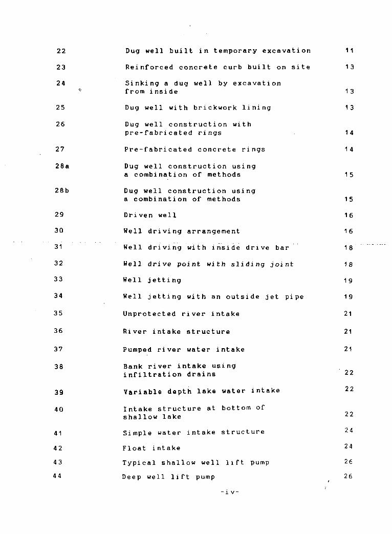
Dug well built in temporary excavat
Reinforced concrete curb built on s
Sinking a dug well by excavation from inside
Dug well with brickwork lining
Dug well construction with pre-fabricated rings
Pre-fabricated concrete rings
Dug well construction using a combination of methods
Dug well construction using a combination of methods
Driven well
Hell driving arrangement
H e l l d r i v i n g w i t h i n s i d e d r i v e b a r
H e l l d r i v e p o i n t w i t h s l i d i n g j o i n t
Hell jetting
Hell jetting with an outside jet pi
Unprotected river intake
River intake structure
Pumped river water intake
Bank river intake using infiltration drains
Variable depth lake water intake
Intake structure at bottom of shallow lake
Simple water intake structure
Float intake
Typical shallow well lift pump
Deep well lift pump
-i v-
45 Reciprocating force pumps 27
46 Cross-section of a diaphragm pump 27
47 Cross-section of a rotary pump 27
48 Cross-section of semi-rotary pump 29
49 Cross-section of helical rotor pump 29
50 Bucket pump 29
51 Chain pump 29
52 Hand pump nomenclature 30
53 Battle pumps - Shallow well
configuration 31
54 Battle pump - Deep well configuration 32
55 New no. 6 pump ( Bangladesh) 33
56 Hydro - pompe Vergnet Schematic
arrangement 34
57 U. S. T. (Kumasi) Hand pump 35
58 The Petro pump 37
59 Polyvinyl chloride ( PVC)
plastic hand pump 38
60 India Mark - II Hand pump 39
61 The "Kangaroo" pump 40
62 The two stroke reciprocating type
well pumps 41
63 Centrifugal pump (Volute-type casing) 42
64 Vertical spindle pump motor for driving
the multistage bore-hole pump 43 65 Shaft driven multistage bore-hole pump
( Harland Engineering Co. Ltd. ) 44 66 Helical rotor pump 45 67 Shaft-driven pumps 47
• v -

68
69
70
71
72
73
74
75a
75b
75c
Pumpdriven by a close-coupled submersible electric motor
Submersible pump (exploded view)
Multilpe-tray aerator
Cascade aerator
Multiple plateform aerator
Hand operated aeration/fi1tration unit for iron removing
Indian Iron removal unit
Chlorination pot with holes at the bottom
Double pot chlorinator
Equipment for feeding chlorine solution
48
49
52
52
53
53
54
55
55
-1 -
I. Rainwater Collection Systems
Rainwater collection is an important source of domestic water supply especially where
the groundwater resources are unavailable or costly to develop.
rainfall is heavy in storms of considerable intensity, with intervals during which there is practically no or very little rainfall.
Depending upon the situations, the catchment of water is on the ground or the runoff from roofs is collected and stored properly. These are explained below:
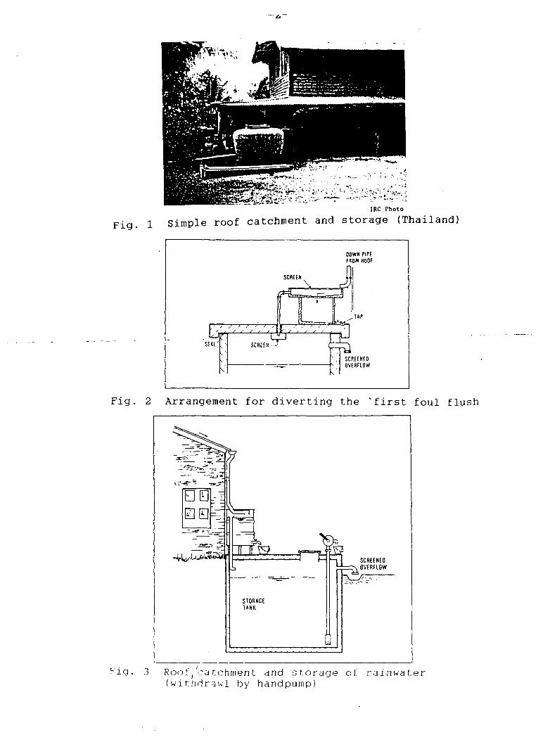
1- Roof catchments: Reasonably pure rainwater can be collected from house roofs made of tiles, slates, galvanised iron, aluminium or asbestos cement sheeting. Figures 1 through 3 are few examples of roof catchments.
2. Ground catchments: These are used for collecting rainwater runoff. Better collection of rainwater can be done from the sloping ground catchments covered with impervious materials like tiles, concrete, asphalt or plastic sheeting. Figure 4 is an example of ground catchment.
3. Storage and preservation: Storage facilities should be provided with enclosures to prevent any contamination from human or animals, leaves, dust or other pollutants entering the storage container. To prevent algal growth and the breeding of mosquito larvae, dark storage conditions should be maintained.
Storage facilities can be above ground or below ground. Below ground facilities have the general advantage of being cool, no water loss through evaporation, and space and construction cost is saved. Figure 5 is an example of such a facility where cement may be used for plastering the excavation walls, or simple shee t i ng.
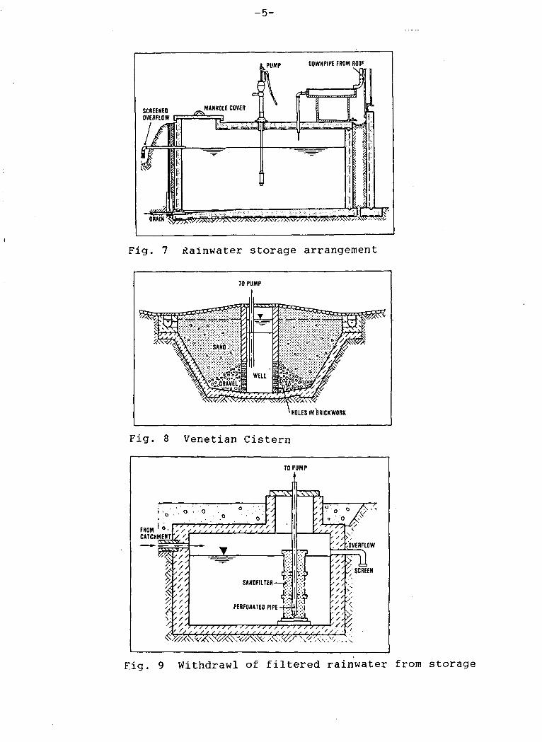
Another underground tank consisting of bee-hive structures as shown in Figure 6 has been used in many countries including Sudan, Botswana, Brazil etc. Two more examples of rainwater storage are shown in Figures 7 and 8.
The quality of rainwater collected from the roof or ground catchment may deteriorate through the putrefation of organic material, growth of bacteria and other microorganisms in the water. The following control measures to protect the quality of stored water are necessary: (i) exclusion of light from the stored water (ii) cool storage conditions and regular cleaning, (iii) disinfection of water by the use of simple devices like chlorination pot etc. An example of rainwater preservation is shown in Figure 9.
IRC Photo
Simple roof catchment and storage (Thailand)
OOWN PIPE FROM ROOF
SCREEN^
\
Xj&if'f'<''''% SEAL
.TtfT-S?.
SCREEN zp , / / <- f t
SCREENED OVERFLOW
Arrangement for diverting the 'first foul flush
• 0 00 fc=m
4VU*uU£v =£>
TiTF? > ,
STORAGE TANK
s rrt
SCREENED OVERFLOW
Roof,catchment and storage of rainwater (withdraw! by handpump)
-3-
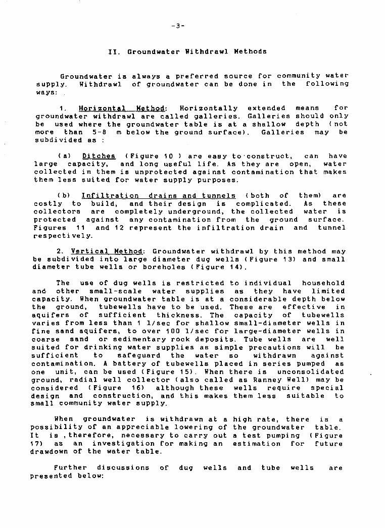
II. Groundwater Withdrawl Methods
Groundwater is always a preferred source for community water supply. Hithdrawl of groundwater can be done in the following ways:
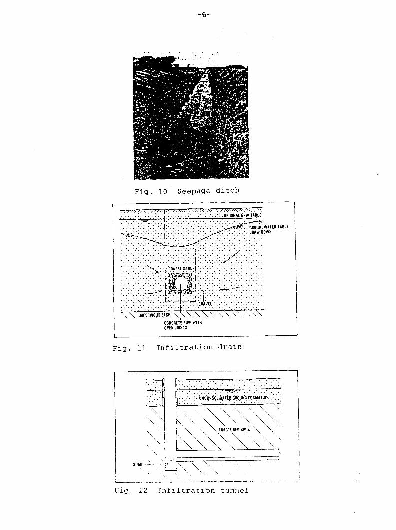
1. Horizontal Method: Horizontally extended means for groundwater withdrawl are called galleries. Galleries should only be used where the groundwater table is at a shallow depth (not more than 5-8 m below the ground surface). Galleries may be subdivided as :
(a) Ditches (Figure 10 ) are easy to • construct, can have large capacity, and long useful life. As they are open, water collected in them is unprotected against contamination that makes them less suited for water supply purposes.
(b) Infiltration drains and tunnels ( both of them) are costly to build, and their design is complicated. As these collectors are completely underground, the collected water is protected against any contamination from the ground surface. Figures 11 and 12 represent the infiltration drain and tunnel respecti vely.
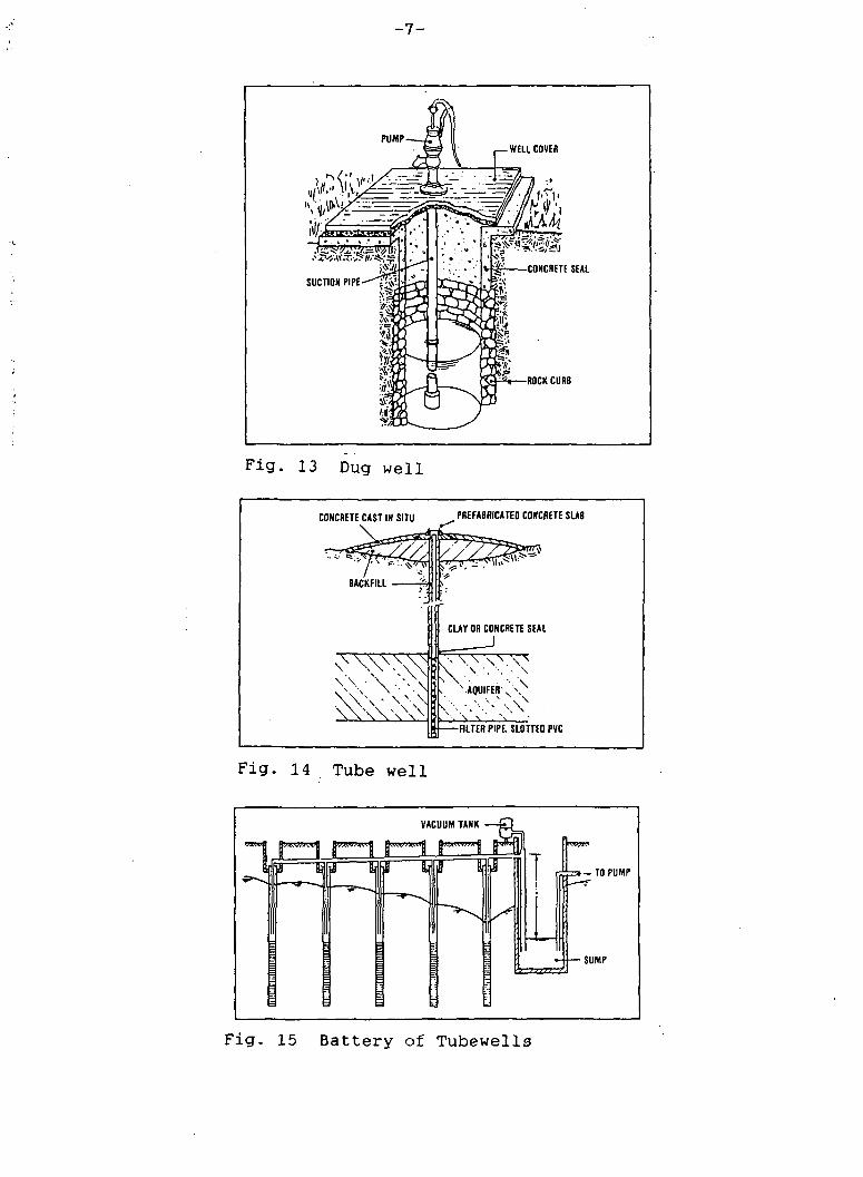
2. Vertical Method: Groundwater withdrawl by this method may be subdivided into large diameter dug wells (Figure 13) and small diameter tube wells or boreholes (Figure 14).
The use of dug wells is restricted to individual household and other small-scale water supplies as they have limited capacity. When groundwater table is at a considerable depth below the ground, tubewells have to be used. These are effective in aquifers of sufficient thickness. The capacity of tubewells varies from less than 1 1/sec for shallow small-diameter wells in fine sand aquifers, to over 100 1/sec for large-diameter wells in coarse sand or sedimentary rock deposits. Tube wells are well suited for drinking water supplies as simple precautions will be sufficient to safeguard the water so withdrawn against contamination. A battery of tubewells placed in series pumped as one unit, can be used (Figure 15). When there is unconsolidated ground, radial well collector (also called as Ranney Hell) may be considered (Figure 16) although these wells require special design and construction, and this makes them less suitable to small community water supply.
Hhen groundwater is withdrawn at a high rate, there is a possibility of an appreciable lowering of the groundwater table. It is .therefore, necessary to carry out a test pumping (Figure 17) as an investigation for making an estimation for future drawdown of the water table.
Further discussions of dug wells and tube wells are presented below:

— *-
Fig . 4 Ground catchment
— i i —
STOBEO WATER — r *
* WELL BOTTOM PROTECTIVE LATER
Fig. 5 Underground rainwater storage well (as used in China)
STONE RIPRAP
-PLASTIC SHEET
STONES OR BRICKS
Fig. 6 Beehave structure storage well
- 5 -
PUMP
- /S i MANHOLE COVER
OOWNPIPE FROM ROOF
=E
CI
&x&z^}n^^
Fig. 7 Rainwater storage arrangement
10 PUMP
^ f f
HOLES IN BRICKWORK
Fig. 8 Venetian Cistern
TO PUMP
FROM CATCHMENT Sfc
SANDFILTER-
PERFORATED PIPE •
> / } / ? T-rr1?
Fig. 9 Withdrawl of filtered rainwater from storage
-6-
Fig. 10 Seepage ditch
. . . . . . . . . . . ^ ; • ; • : • : - ; • : • : - : - , : • : - : • : • : : - ; • ; ORIGIN AL c/w TABLE
•COARSE SANQ-1
I.-I?^
•:i£ss£
IMPERVIOUS BASE,
^ GRAVEL-:
CONCRETE PIPE WITH OPEN JOINTS
:•: GROUNDWATER TABLE DRAWDOWN
\ \ \ \ \ \ \ \
Fig. 11 I n f i l t r a t i o n drain
SUMP-
;UNCONSOLIDATED GROUND FORMATION-:
\
\ \ \ \ \ \ \ \ \FRACTURED ROCK \ \
\ \ = ) •
\ \
Fig. 12 I n f i l t r a t i o n tunnel
- 7 -
,— WELL COVER
-mmi SUCTION PIPE-— i H V
4 W^l.^1 CONCRETE SEAL
ROCK CURB
F i g . 13 Dug w e l l
CONCRETE CAST IN SITU
|[
PREFABRICATED CONCRETE SUB
>
CLAY OR CONCRETE SEAL
> \ A 0 U I F E R \ \ N
k . \ s •. \ , ' FILTER PIPE. SLOTTED PVC
F i g . 14 . Tube w e l l
VACUUM TANK
^
B W V . ' A ^ t m n n f l Dw.v.>*.njj ^ M ^ V J M I
Ira m ERfdl ui I T >-T0PUMP
•SUMP
Fig. 15 Battery of Tubewells

- e -
2 TO 3 M. -I h
kVV/ / /AVW.W VW/.
GROUNDWATER FORMATIONS 'OF LOW PERMEABILITY
AQUIFER '
^ ^
Fig. 16 Radical collector well (Ranney Well)
-GROUNDWATER TABLE BEFORE AND DURING
-PUMPING
X X X X X X X X X X X X X IMPERVIOUS BASE XXXY>
Fig . 17 Test pumping
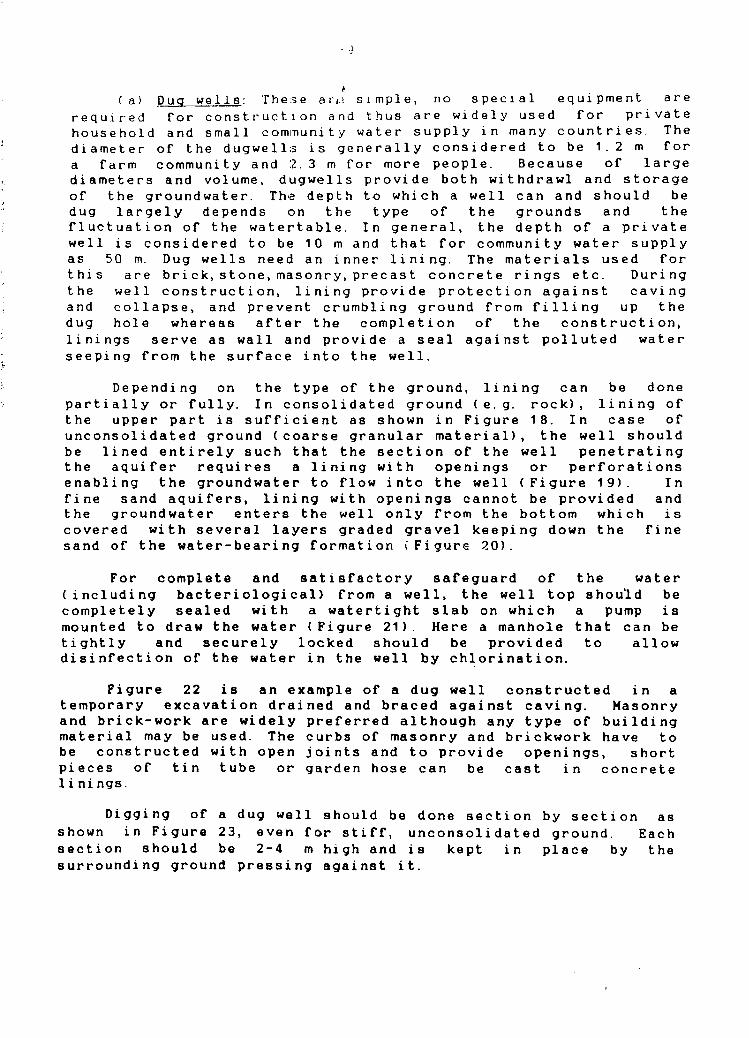
(a) Dug well 8: These a t,.? simple, no special equipment are required for construction and thus are widely used for private household and small community water supply in many countries. The diameter of the dugwells is generally considered to be 1.2 m for a farm community and 2.3 m for more people. Because of large diameters and volume, dugwells provide both withdrawl and storage of the groundwater. The depth to which a well can and should be dug largely depends on the type of the grounds and the fluctuation of the watertable. In general, the depth of a private well is considered to be 10 m and that for community water supply as 50 m. Dug wells need an inner lining. The materials used for this are brick,stone, masonry, precast concrete rings etc. During the well construction, lining provide protection against caving and collapse, and prevent crumbling ground from filling up the dug hole whereas after the completion of the construction, linings serve as wall and provide a seal against polluted water seeping from the surface into the well.
Depending on the type of the ground, lining can be done partially or fully. In consolidated ground (e.g. rock), lining of the upper part is sufficient as shown in Figure 18. In case of unconsolidated ground (coarse granular material), the well should be lined entirely such that the section of the well penetrating the aquifer requires a lining with openings or perforations enabling the groundwater to flow into the well (Figure 19). In fine sand aquifers, lining with openings cannot be provided and the groundwater enters the well only from the bottom which is covered with several layers graded gravel keeping down the fine sand of the water-bearing formation (Figure 20).
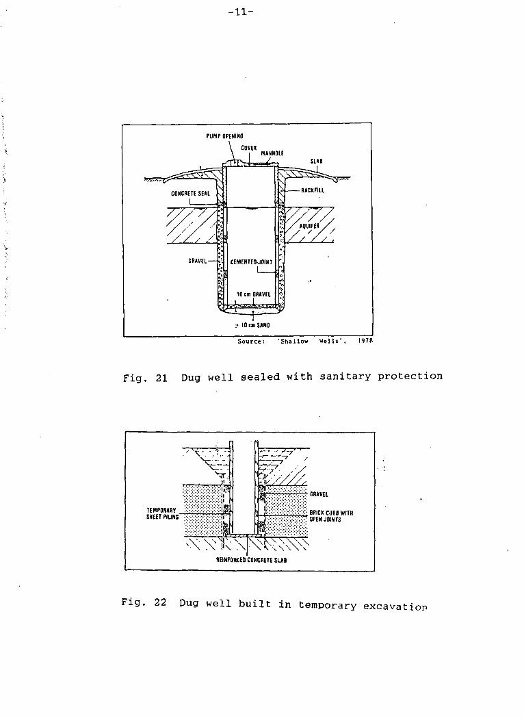
For complete and satisfactory safeguard of the water (including bacteriological) from a well, the well top should be completely sealed with a watertight slab on which a pump is mounted to draw the water (Figure 21). Here a manhole that can be tightly and securely locked should be provided to allow disinfection of the water in the well by chlorination.
Figure 22 is an example of a dug well constructed in a temporary excavation drained and braced against caving. Masonry and brick-work are widely preferred although any type of building material may be used. The curbs of masonry and brickwork have to be constructed with open joints and to provide openings, short pieces of tin tube or garden hose can be cast in concrete li ni ngs.
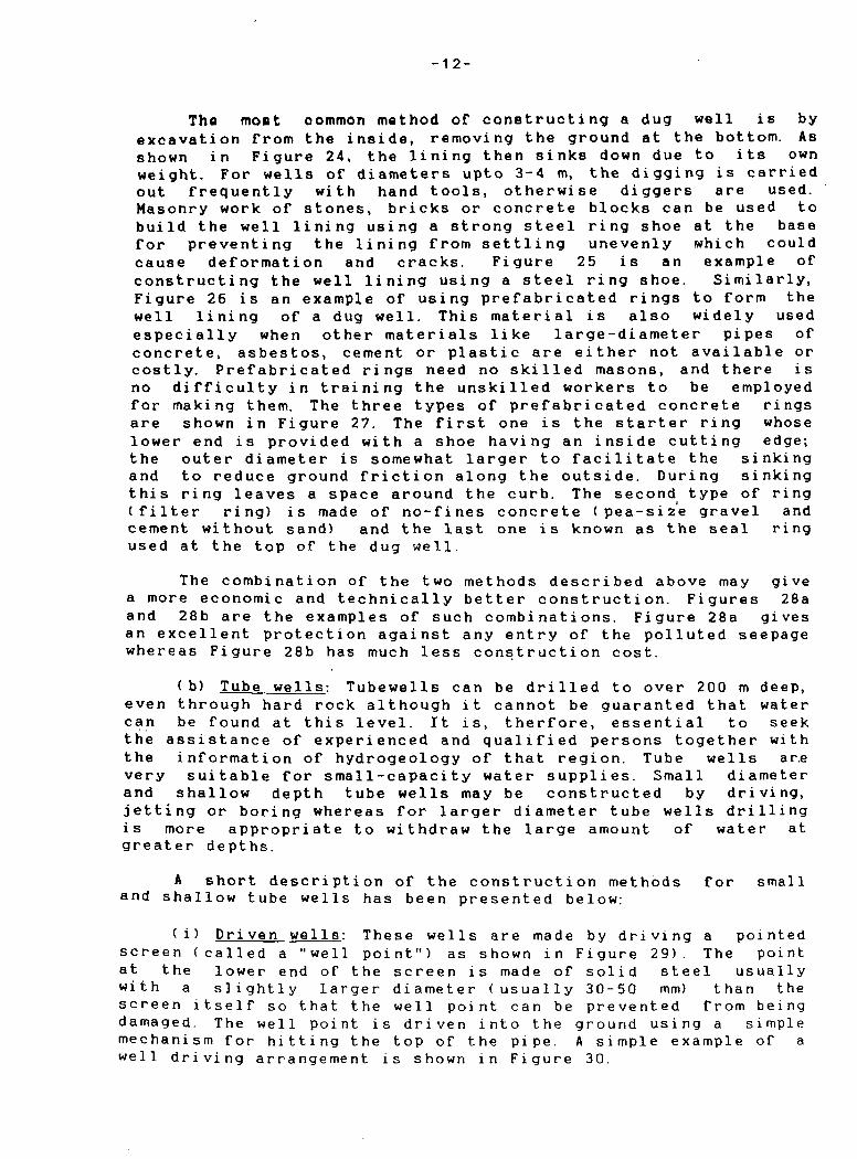
Digging of a dug well should be done section by section as shown in Figure 23, even for stiff, unconsolidated ground. Each section should be 2-4 m high and is kept in place by the surrounding ground pressing against it.

- 1 0 -
TOP SOIL
WEATHERED ROCK
FISSURED flOCK
V
-CONCflF rE CURB
G/W IA8LE
Fig. 18 Dug well in rock fomation
: . » • • • ; . . 7 . . . J M '•
CONCRETE CURB-
IMPERVIOUS FORMATIONS
•:-COARSE •: ••'GRAINED'' .'.AQUIFER-
Fig. 19 Dug well in coarse granular material
IMPERVIOUS FORMATION
.._. - • - * -
-*• J *
. 1 - .•-•-•. .
CONCRETE CURB
G/W TABLE
-COARSE GRAVEL
J / t i \ s
'.- / . / . [ A v .
. FINE GRAINEO ' . /AQUIFER
Fig. 20 D u g w e H in fine granular aquifier
- 1 1 -
PUMP OPENING
COVER
•WSi -v . -g^
GRAVEL-
MAHHOLE
CEMENTED JOIHT
SLAB
• ^ 5 3
+ 10 cm SAND
Source: 'Shsllow Wells' 1978
Fig. 21 Dug well sealed with sanitary protection
TEMPORARY SHEET PILING"
REINFORCED CONCRETE SLAB
hr7 ~r GRAVEL
.(.•: ..:•'• . BRICK CURB WITH
. •. OPEN JOINTS
Fig. 22 Dug well built in temporary excavati
-12-
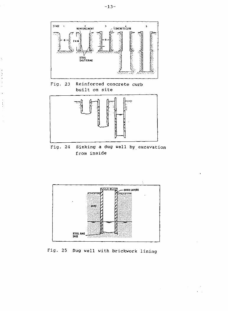
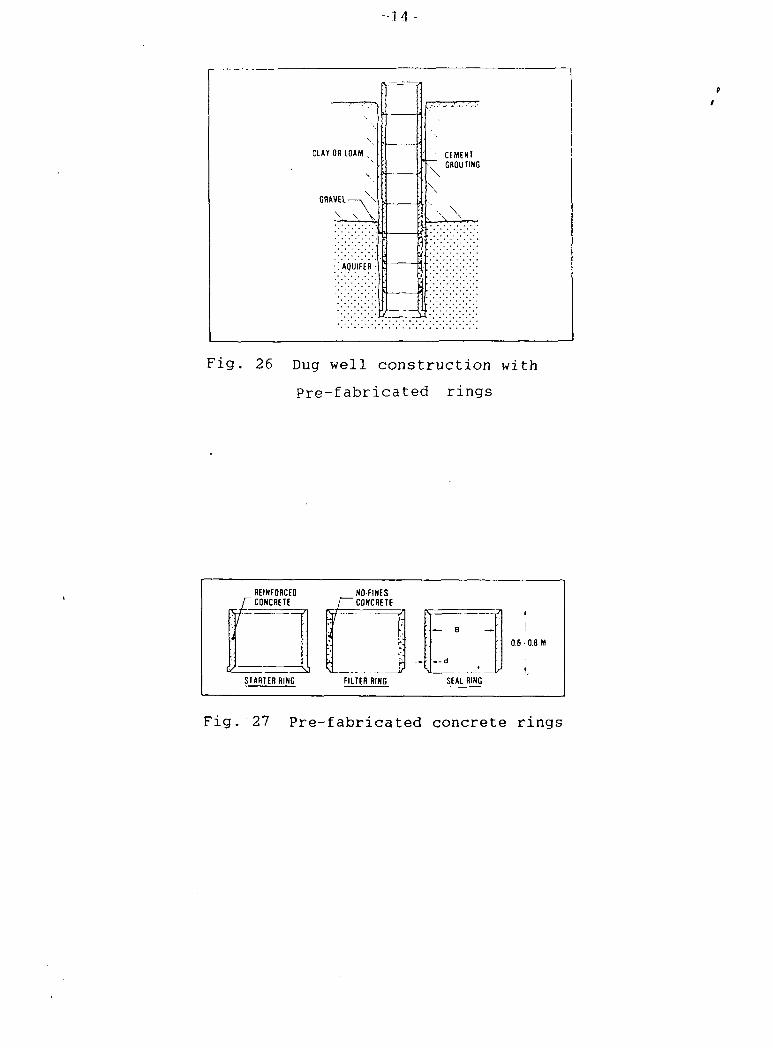
The most oommon method of constructing a dug well is by excavation from the inside, removing the ground at the bottom. As shown in Figure 24, the lining then sinks down due to its own weight. For wells of diameters upto 3-4 m, the digging is carried out frequently with hand tools, otherwise diggers are used. Masonry work of stones, bricks or concrete blocks can be used to build the well lining using a strong steel ring shoe at the base for preventing the lining from settling unevenly which could cause deformation and cracks. Figure 25 is an example of constructing the well lining using a steel ring shoe. Similarly, Figure 26 is an example of using prefabricated rings to form the well lining of a dug well. This material is also widely used especially when other materials like large-diameter pipes of concrete, asbestos, cement or plastic are either not available or costly. Prefabricated rings need no skilled masons, and there is no difficulty in training the unskilled workers to be employed for making them. The three types of prefabricated concrete rings are shown in Figure 27. The first one is the starter ring whose lower end is provided with a shoe having an inside cutting edge; the outer diameter is somewhat larger to facilitate the sinking and to reduce ground friction along the outside. During sinking this ring leaves a space around the curb. The second type of ring (filter ring) is made of no-fines concrete (pea-size gravel and cement without sand) and the last one is known as the seal ring used at the top of the dug well.
The combination of the two methods described above may give a more economic and technically better construction. Figures 28a and 28b are the examples of such combinations. Figure 28a gives an excellent protection against any entry of the polluted seepage whereas Figure 28b has much less construction cost.
( b) Tube wells: Tubewells can be drilled to over 200 m deep, even through hard rock although it cannot be guaranted that water can be found at this level. It is, therfore, essential to seek the assistance of experienced and qualified persons together with the information of hydrogeology of that region. Tube wells are very suitable for small-capacity water supplies. Small diameter and shallow depth tube wells may be constructed by driving, jetting or boring whereas for larger diameter tube wells drilling is more appropriate to withdraw the large amount of water at greater depths.
A short description of the construction methods for small and shallow tube wells has been presented below:
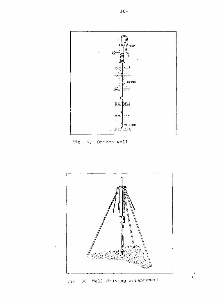
(i) Driven wells: These wells are made by driving a pointed screen (called a "well point") as shown in Figure 29). The point at the lower end of the screen is made of solid steel usually with a slightly larger diameter (usually 30-50 mm) than the screen itself so that the well point can be prevented from being damaged. The well point is driven into the ground using a simple mechanism for hitting the top of the pipe. A simple example of a well driving arrangement is shown in Figure 30.
-13-
STAGE 1 REINFORCEMENT CONCRETE CURB
A^777.
^ / 's
•/////.•
W">
&
V-.
Fig. 23 Reinforced concrete curb built on site
Fig. 24 Sinking a dug well by excavation from inside
9 •">/••>'.'
SAKO.
\SV1 l\Sy -BRICK LAYERS
< << / / *
Fig. 25 Dug well with brickwork lining
•1.4-
CLAY OR LOAM .
G R A V E L — \ \
•'. AQUIFER -
I-:-:---:-:-
1 ; = ^ = T
• \
i J
I
/ s
v CEMENT \ GROUTING \ \
Fig. 26 Dug well construction with
Pre-fabricated rings
REINFORCED CONCRETE
LL
NO-FINES "CONCRETE
isi STARTER RING
— B —
— a M
0.6 • 0.8 M
FILTER RING SEAL RING
Fig. 27 Pre-fabricated concrete rings

- 1 5 -
wmf^ /
REINFORCED CONCRETE y "CURB CAST IM SITU
CONCRETE CURB MADE OF PREFAB RINGS
Fig.28 * a' Dug well construction using a
combination of methods
\ COMPACTEO BACKFILL
\ \
v PLATFORM
• / / • v / , / / ^ } ;
. • . - . - . • . PREFABICATEO ^vi W . V CONCRETE RINGS ^
T53
ASBESTOS / CEMENT PIPE /,
/ /
faji /^GRAVEL
: - : • : - : • : - A Q U I F E R :
Fig. 28 ' b ' Dug well c o n s t r u c t i o n using a
combination of methods
-16-
Fig. 29 Driven well
Fig. 30 Well driving arrangement
-17-
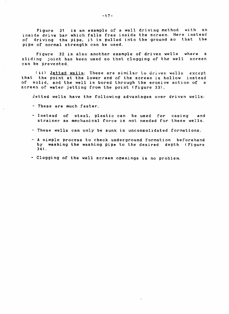
Figure 31 is an example of a well driving method with an inside drive bar which falls free inside the screen. Here instead of driving the pipe, it is pulled into the ground so that the pipe of normal strength can be used.
Figure 32 is also another example of driven wells where a sliding joint has been used so that clogging of the well screen can be prevented.
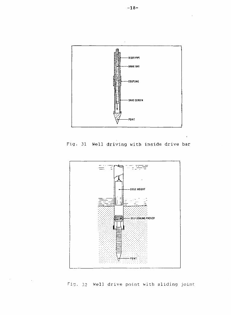
(ii) Jetted wells: These are similar to driven wells except that the point at the lower end of the screen is hollow instead of solid, and the well is bored through the erosive action of a screen of water jetting from the point (Figure 33).
Jetted wells have the following advantages over driven wells:
- These are much faster.
- Instead of steel, plastic can be used for casing and strainer as mechanical force is not needed for these wells.
- These wells can only be sunk in unconsolidated formations.
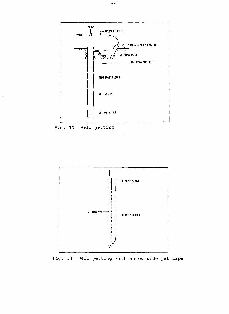
- A simple process to check underground formation beforehand by washing the washing pipe to the desired depth (Figure 34) .
Clogging of the well screen openings is no problem.
- 1 8 -
I
11
T
-HISER PIPE
-DRIVE BAR
-COUPLING
-SAND SCREEN
-POINT
Fig. 31 Well driving with inside drive bar
r-»4ci
£
a
-ORIVE WEIGHT
'SELF SEALING PACKER
•/y'•''••'••'• POINT!
Fig. 39 Well drive point with sliding joint
TO RIG
SWIVEL- JZ PRESSURE HOSE
"•1
PRESSURE PUMP 4 MOTOR
s m^£ SETTLING BASIN
. GROUNDWATER TABLE
-TEMPORARY CASING
-JETTING PIPE
JETTING NOZZLE
Fig. 33 Well jetting
JETTING PIPE-
-PLASTIC CASING
-PLASTIC SCREEN
V /IN
Fig. 34 Well jetting with an outside jet pipe
-20-
III. Surface Hater Intake
1. River water intake: A river water intake can be sited at any suitable point where water can be withdrawn sufficiently since the quality of the water does not usually differ much across the width and depth of the river bed. One should design the river water intake in such a way that both clogging and scouring will be avoided and its stability should be secured even under flood condi t i ons.
Figure 35 is an example of a river water intake which is unprotected. If the river transports no boulders or rolling stones that will damage the intake, such unprotected intakes may be sufficient.
Intake structures as shown in Figure 36 is suitable where intake protection is necessary. To prevent the entry of any boulders and rolling stones, the bottom of the intake structure should be at least 1 m above the river bed.
Figure 37 is an example of a river water intake using a suction pump. If the variation between the high and low level of water in the river is not more than 3. 5-4 m, use of this pump may be sufficient.
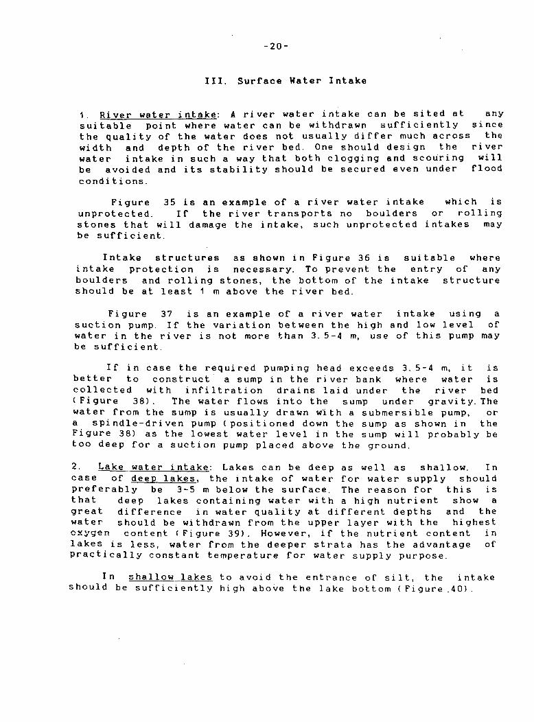
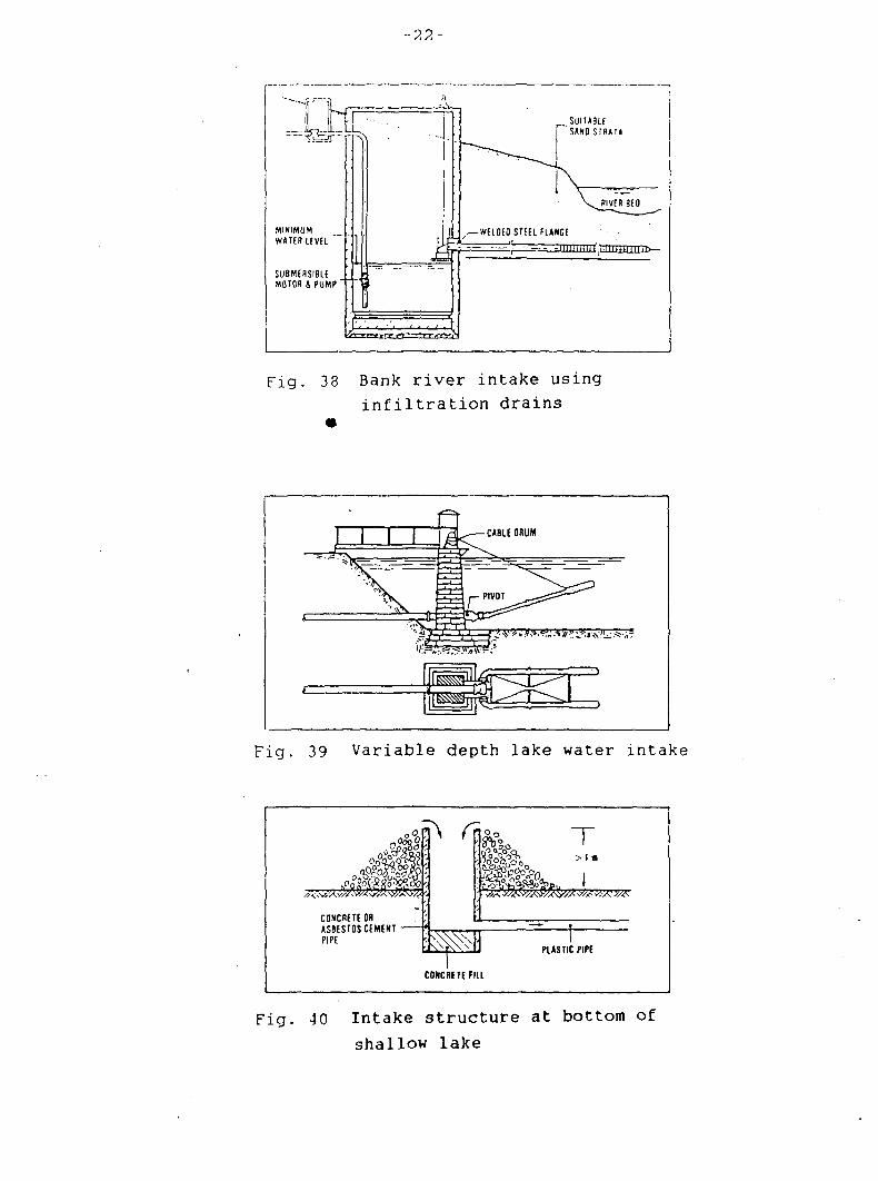
If in case the required pumping head exceeds 3. 5-4 m, it is better to construct a sump in the river bank where water is collected with infiltration drains laid under the river bed (Figure 38). The water flows into the sump under gravity.The water from the sump is usually drawn with a submersible pump, or a spindle-driven pump (positioned down the sump as shown in the Figure 38) as the lowest water level in the sump will probably be too deep for a suction pump placed above the ground.
2. Lake water intake: Lakes can be deep as well as shallow. In case of deep lakes, the intake of water for water supply should preferably be 3-5 m below the surface. The reason for this is that deep lakes containing water with a high nutrient show a great difference in water quality at different depths and the water should be withdrawn from the upper layer with the highest oxygen content (Figure 39). However, if the nutrient content in lakes is less, water from the deeper strata has the advantage of practically constant temperature for water supply purpose.
In shallow lakes to avoid the entrance of silt, the intake should be sufficiently high above the lake bottom (Figure.40).

-21-
HIGH W/L WlTKy.l'lHAMJm.V.MI AW,
"ft
> » > y r't P i vf
Fig. 35 Unprotected river intake
TI rr i| Y II
- t r - i
F-4
II i l
|l il
"Till
- H -II II II
\ . , > A > > » ' ) , » ,i> . . >\
mz$; \<tfc^' ' ' mv<
-SCREENS
I - -
Fig. 36 River intake structure
HIGH W/L
LOW W/L
_J3£ s . W/TWW..- v"^^ -
,4 ^
/ • .
„_Jf^ ^j^^\w/A<j.vi/.'.'X\w7*r:
VARIATION BETWEEN HIGH ANO LOW* WATEBLEVEL
- TO SUPPLY
UP TO 3.5-4 m
Fig. 37 Pumped river water intake
-22-
SUITA8U SANO STRATH
Fig. 33 Bank river intake using infiltration drains
PSP Q \B^—CABLE ORUM
^ t ^
ggj^r^-X^7
T^^m^L
Fig. 39 Variable depth lake water intake
a\ rn
CONCRETE OR ASBESTOS CEMENT -PIPE
v?--
T > I m
' /VJoOoo. - i i
^ T= PLASTIC PIPE
CONCRETE F i l l
Fig. 40 Intake structure at bottom of
shallow lake

-23-
For small community water supply the quantity of water needed is less and therefore, construction of a small capacity intake is sufficient. Figure 41 is an example of construction of such intake with simple arrangements using flexible plastic pi pes.
Similarly, another type of intake construction using a floating barrel to support the intake pipe, is shown in Figure 42 where the water is pumped from the well sump.

-24-
Fig. 41 Simple water intake structure
WELL SUMP BARREL
FLEXIBLE JOINT RUBBER Ofl PLASTIC HOSE
Fig. 42 Float intake
-25-
IV. Pumps used in Hater Supply
In small community water supply, pumps are used for: (i) pumping water from wells; (ii) pumping water from surface water intake; and iii) pumping water into storage reservoirs and the distribution system, if any.
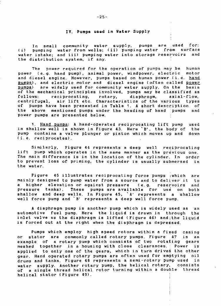
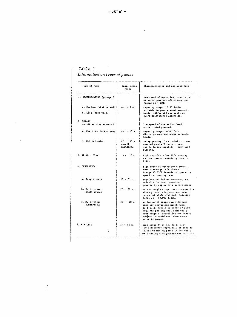
The power required for the operation of pumps may be human power (e.g. hand pump), animal power, windpower, electric motor and diesel engine. However, pumps based on human power (i.e. hand pumps) . and electric motor and diesel engine (often called power pumps) are widely used for community water supply. On the basis of the mechanical principles involved, pumps may be classified as follows: reciprocating, rotary, diaphragm, axial-flow, centrifugal, air lift etc. Characteristics of the various types of pumps have been presented in Table 1. A short description of the above mentioned pumps under the heading of hand pumps and power pumps are presented below.
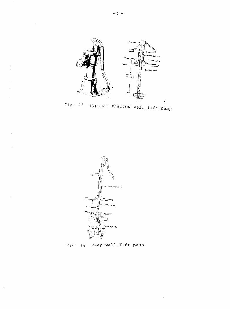
1. Hand pumps: A hand-operated reciprocating lift pump used in shallow well is shown in Figure 43. Here 'B* , the body of the pump contains a valve plunger or piston which moves up and down (i.e. reciprocates).
Similarly, Figure 44 represents a deep well reciprocating lift pump which operates in the same manner as the previous one. The main difference is in the location of the cylinder. In order to prevent loss of priming, the cylinder is usually submersed in the water.
Figure 45 illustrates reciprocating force pumps iwhich are mainly designed to pump water from a source and to deliver it to a higher elevation or against pressure (e.g. reservoirs and pressure tanks). These pumps are available for use on both shallow and deep wells. In Figure 45, 'A' represents a shallow well force pump and * B' represents a deep well force pump.
A diaphragm pump is another pump which is widely used as an automotive fuel pump. Here the liquid is drawn in through the inlet valve as the diaphragm is lifted (Figure 46) and the liquid is forced out at the right when the diaphragm is depressed.
Pumps which employ high speed rotors within a fixed casing or stator are commonly called rotary pumps. Figure 47 is an example of a rotary pump which consists of two rotating gears meshed together in a housing with close clearances. Power is applied to only one of the gears, which in turn drives the other gear. Hand operated rotary pumps are often used for emptying oil drums and tanks. Figure 48 represents a semi-rotary pump used in water supply. Another rotary pump, the helical rotary, consists of a single thread helical rotor turning within a double thread helical stator (Figure 49).
- 25 * a'
Table 1 Information on types of pumps
Type of Pump Usual depth
range
Characteristics and Applicability
1. RECIPROCATINC (plunger)
a. Suction (shallow well)
b. Life (deep well)
2. ROTAKY
(positive displacement)
4. Chain and bucket pump
b. Helical rotor
2. AXlAL - FLUW
U. CE.VTRIFUCAL
up to 7
a. Single-stage
b. Multi-stage
shatt-driven
c. Multi-stage
submersible
5. AIR LIFT
up to 10 m.
25 - 150 m.
usual ly
submerged
25 - 50
low speed of operation; hand, wind
or o»otor powered; efficiency low
(range 25 - 601)
capacity range: 10-50 l/min;
suitable to pump against variable
heads; valves and cup seals re
quire maintenance attention.
Low speed of operation; hand,
animal, wind powered;
capacity range: 5-30 1/ain.
discharge constant under variable
heads.
using gearing: hand, wind or aotor
powered good efficiency; best
suited to low capacity - high lift
pumping.
high capacity - low lift pumping;
can pump water containing sand or
silt.
high speed of operation - smootl.,
even discharge; efficiency
(range 50-852) depends on operating
speed and pumping head.
requires skilled maintenance; not
suitable for hand operation;
powered by engine or electric motor.
as for single stage. Motor accessible,
above ground; alignment and lubri
cation of shaft critical; capacity
range 25 - 10,000 1/nin.
as for multi-stage shaft-driven;
smoother operation; maintenance
difficult; repair to motor or pump
requires pulling unit from well;
vide range of capacities and heads;
subject to rapid wear when sandy
water is pumped.
high capacity at low lift; very
low efficiency especially at greater
lifts; no moving parts in the veil;
w*!1 casing straightucss not critical.
- ?. f> -
rig
Hi I
pump
• |iL_ i f — °'0» p,,.
;--%lrri:~~"'"
Fig. 44 Deep well lift pump

- 2 7 -
Air «M**b*f
Sfl^ H©l H»or«
l*>«n 2 2 '
ttglll«*« bo<N^
Air thamb+t
Fig. 45 Reciprocating force pumps
Fig. 46 Cross-section of a diaphragm pump
0<icrt«r9»
Fig. 47 Cross-section of a rotary pump

-28-
Figure 50 is an example of bucket pump which is also used in the field of water supply. Small buckets attached to an endless chain are rotated over sprockets so that each bucket dips from the source at the bottom, carries it to the top, and empties it into the spout as it passes over the top sprocket.
Chain pump is also used in the field of water supply, mainly on cisterns and dug wells. In this pump, rubber discs attached to an endless chain running over a sprocket at the top are pulled upward through a pipe to lift water mechanically upto the spout. Figure 51 is an example of this pump.
Reciprocating hand pumps in use today represents the evolutionary, empirical products of over a century of design modifications. Many of them are copies of commercially successful pumps. A reciprocating hand pump nomenclature is shown in Figure 52. Although the nomenclature of hand pump varies widely by and even within countries, this nomenclature used herein is the common one. This pump nomenclature is composed of three main parts: (i) pump stand assembly(ii) pump cylinder assembly (iii) connecting assembly. In case of deep well, these three assemblies are separately located whereas in case of shallow wells the cylinder assembly and connecting rod may be located within the pump stand. These three component assemblies can be and often are purchased separately. As the result of hand pumps development suitable to the rural conditions of developing countries, a variety of hand pumps are presently available for use. Some of these pumps are presented below.
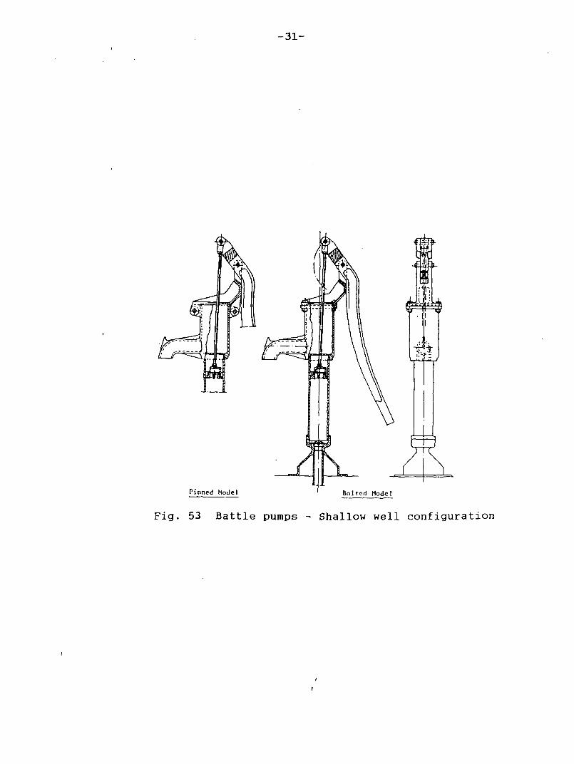
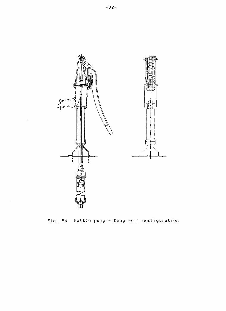
(i) Battlle Hand Pump: This is a hand pump developed by Battlle Memorial Institute-Columbus Laboratories as per the contract with USAID in 1966. The Battle pump for deep and shallow well configurations are presented in Figures 53 and 54 respectively. These pumps are in use in Thailand, Nigeria, Bangaladesh, Ecuador, Honduras, Guatemala, The Philippines, Sri-Lanka, Tunisia, and also Dominical Republic, Indonesia and Nicaragua. The following advantages of these pumps have been reported: spare parts availability, easy maintenance, low cost, durability, employment creation, increase of local income and the reduction of the foreign exchange outflow.
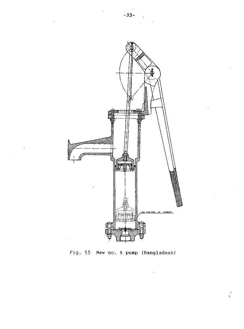
(ii) New No. 6 Pump: This pump is a combination between the Battlle pump and Maya No. 6 pump. It was implemented by UNICEF in Bangladesh. This hand pump is 15% lighter than the Battelle pump. Figure 55 is an example of this pump.
(iii) Hydro-Pompe Verqent: This pump is French made and has a novel opertating mode. This pump is widely used in Africa. A schematic diagram of this pump is shown in Figure 56.
(iv) U. S. T. ( Kumasi) hand pump: Since 1972, a hand pump suitable for local manufacture was developed at the University of Science and Technology, Kumasi, Ghana. This pump has been shown in Figure 51. Although preliminary testing has been carried out at depths upto 100 ft, testing ig still in progress.

- 2 9 -
S~
Check t
F i g . 48 C r o s s - s e c t i o n of s e m i - r o t a r y pump
Meter edeeier cevpllne
_ Rubber t i t ter bended 10 pipe
. Suction »eive end •trainer • • • •mb 'y
F i g . 49 C r o s s - s e c t i o n of h e l i c a l r o t o r pump
ftubb«r dlie»
Rto ioduc t<S I ' d " WHO Mono^ ' I pK NO * 7
F i g . 50 Bucket pump F i g . 51 Chain pump

- 3 0 -
FULCRUMv
CAP
PUMP ROD
DROP PIPE
' — - l -
CAP
DISCHARGE CHECK VALVE
CUPS-
SUCTION CHECK VALVE —
C A P -
I T
CYLINDER
F i g . 52 Hand pump n o m e n c l a t u r e
-31-
Fig. 53 Battle pumps - Shallow well configuration
-32-
jm
a" (. -.1- •
ftr
ffl
Fig. 54 Battle pump - Deep well configuration
- 3 3 -
F i g . 55 New n o . 6 pump (Bangladesh)

- 3 4 -
CONTROL CHECK VALVE
DISCHARGE CHECK VALVE
DIAPHRAGMATIC HOSE
RIGID CYLINDER
SUCTION VALVE
STRAINER
Fig. 56 Hydro - pompe Vergnet Schematic arrangement

- 3 5 -
fulcrum bconng
Drawing : Courtesy A. Abrobah-Cudjoo
F i g . 57 U . S . T . (Kumasi) Hand-pump
-36-
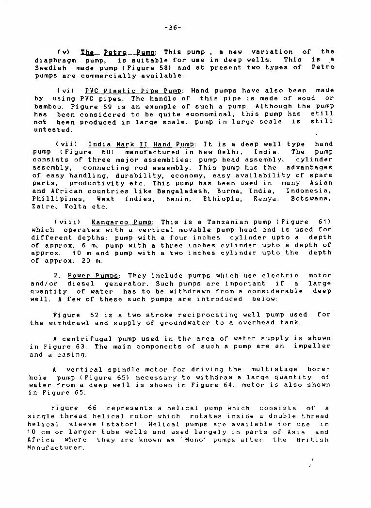
(v) Tha Patro Pump: This pump , a new variation of the diaphragm pump, is suitable for use in deep wells. This is a Swedish made pump (Figure 58) and at present two types of Petro pumps are commercially available.
(vi) PVC Plastic Pipe Pump: Hand pumps have also been made by using PVC pipes. The handle of this pipe is made of wood or bamboo. Figure 59 is an example of such a pump. Although the pump has been considered to be quite economical, this pump has still not been produced in large scale, pump in large scale is still untested.
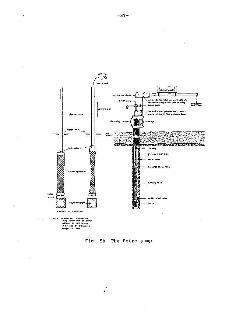
( vii) India Hark II Hand Pump: It is a deep well type hand pump (Figure 60) manufactured in New Delhi, India. The pump consists of three major assemblies: pump head assembly, cylinder assembly, connecting rod assembly. This pump has the advantages of easy handling, durability, economy, easy availability of spare parts, productivity etc. This pump has been used in many Asian and African countries like Bangaladesh, Burma, India, Indonesia, Phillipines, West Indies, Benin, Ethiopia, Kenya, Botswana, Zaire, Volta etc.
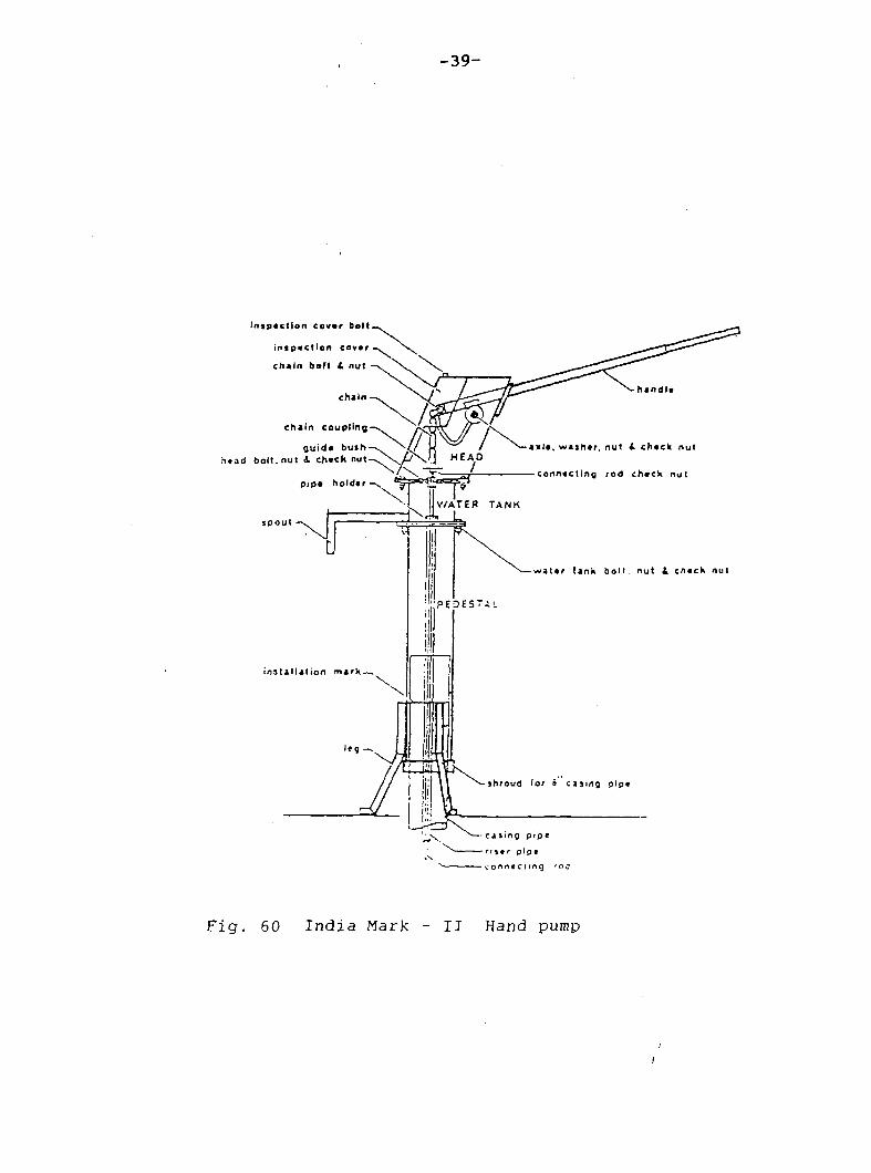
(viii) Kangaroo Pump: This is a Tanzanian pump (Figure 61) which operates with a vertical movable pump head and is used for different depths: pump with a four inches cylinder upto a depth of approx. 6 m, pump with a three inches cylinder upto a depth of approx. 10 m and pump with a two inches cylinder upto the depth of approx. 20 m.
2. Power Pumps: They include pumps which use electric motor and/or diesel generator. Such pumps are important if a large quantity of water has to be withdrawn from a considerable deep well. A few of these such pumps are introduced below:
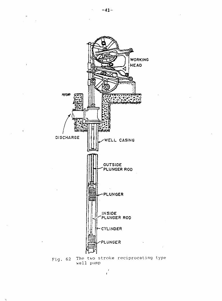
Figure 62 is a two stroke reciprocating well pump used for the withdrawl and supply of groundwater to a overhead tank.
A centrifugal pump used in the area of water supply is shown in Figure 63. The main components of such a pump are an impeller and a casing.
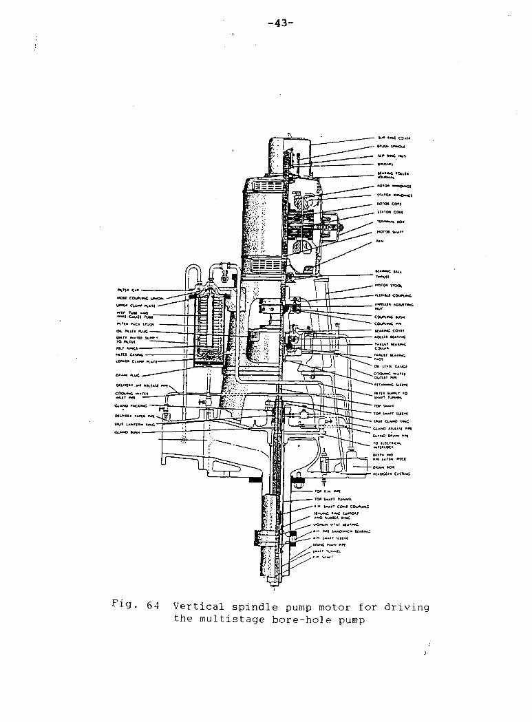
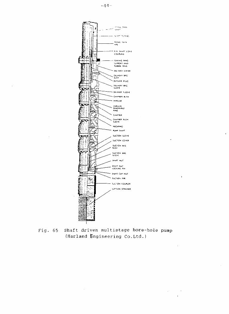
A vertical spindle motor for driving the multistage borehole pump (Figure 65) necessary to withdraw a large quantity of water from a deep well is shown in Figure 64. motor is also shown i n Figure 65.
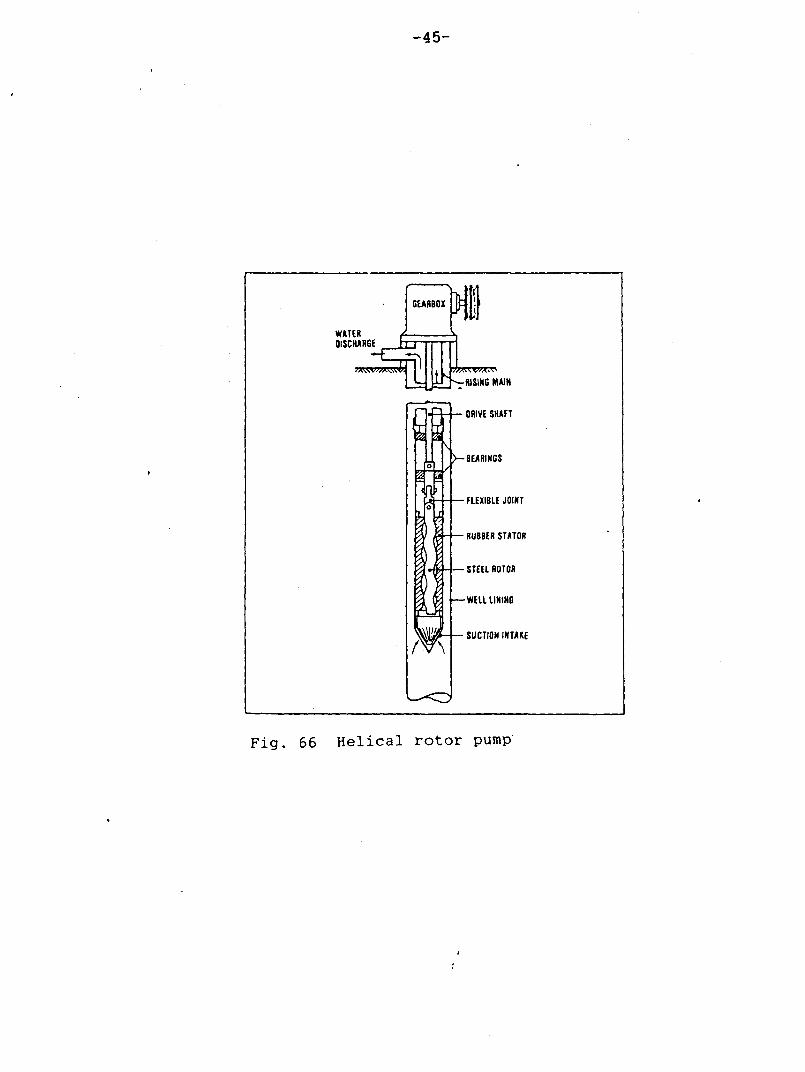
Figure 66 represents a helical pump which consists of a single thread helical rotor which rotates inside a double thread helical sleeve (stator). Helical pumps are available for use in 10 cm or larger tube wells and used largely in parts of Asia and Africa where they are known as Mono' pumps after the British Manufacturer.
- 3 7 -
( water out
-pipe or Not*
sector of circle
l i t ter wi r«
upward pull
pump cylinder'
r7T/ 'A —counter weight— A .
X/f/f/A \/S'
suction check VQIM
oneher
principle of operation
note : alternative method for fixing, tower end of pump cylinder to wtt l eating i t by use of expanding wedget or j c w »
F i g . 58 The P e t r o pump

- 3 8 -
Co*»cr«t» *f brick ( pl*lfO*fn
Z3F
Rubbar wash*r b*l*r««n
1
OJ
^ t -
. Concrt l* . brick or «ro«d post
. i- PVC CMIftf
Low w*l*r |«*«|
Low*' *«lv« • • • ! c«m«nl»d iftald* PVC cvslng n«ar |e(nt
Af te r : Sponr lcr (VITA)
Fig . 59 Polyvinyl c h l o r i d e (PVC) p l a s t i c hand pump
- 3 9 -
Inspection covtr bolt
inspection covtr
chain boft A nut
chain handle
chain coupling
guide bush head bolt, not 4 check n u t - v \ . / / N . ) . | HEAO
spout -
pip* holder-^ *^ f J * - , ' 6^ a ?> 1
-L " j WATER TANK
axle, washer, nut A cheek nut
connecting rod check nut
water tank bolt nut £ check nut
installation mark —
• \ ^ — d sing P'pe
^ riltr p i p e
v v j o n n e c t i n g ' O J
F i g . 60 I n d i a Mark - I I Hand pump
- 4 0 -
4-Handle
Footscand
CYLINDER DOWN TO 10 METERS
5£ 2" CYUNOER DOWN TO 20 METERS
Fig. 61 The "Kangaroo" pump
- 4 1 -
r&gs-
WORKING HEAD
DISCHARGE WELL CASING
OUTSIDE PLUNGER ROD
PLUNGER
INStOE PLUNGER ROD
CYLINDER
PLUNGER
Fig. 62 The two stroke reciprocating type well pump

-42-
TONGUE
CASING
INLET
IMPELLER
F i g . 63 Cen t r i fuga l pump (Volute- type casing)
- 4 3 -
••Oil COWIMC
«•> rutl **o
«U»UT TAf* **f
CLAM) Krt« •
TO* iMA#r iuiv<
VuT O.AMO t««C
0>*t0 l l tMU *1
• — 0***M M l
F i g . 64 Vertical spindle pump motor for driving the multistage bore-hole pump
-41-
m Fig. 65 Shaft driven multistage bore-hole pump
(Harland Engineering Co.Ltd.)
- 4 5 -
WATER DISCHARGE
GEARBOX
>U-te WMVAWt
nTTTT L L UJj RISING M
«
>—BEARINGS
MAIN
DRIVE SHAFT
- FLEXIBLE JOINT
- RUBBER STATOR
- STEEL ROTOR
-WELL LINING
- SUCTION INTAKE
Fig. 66 Helical rotor pump

-46-
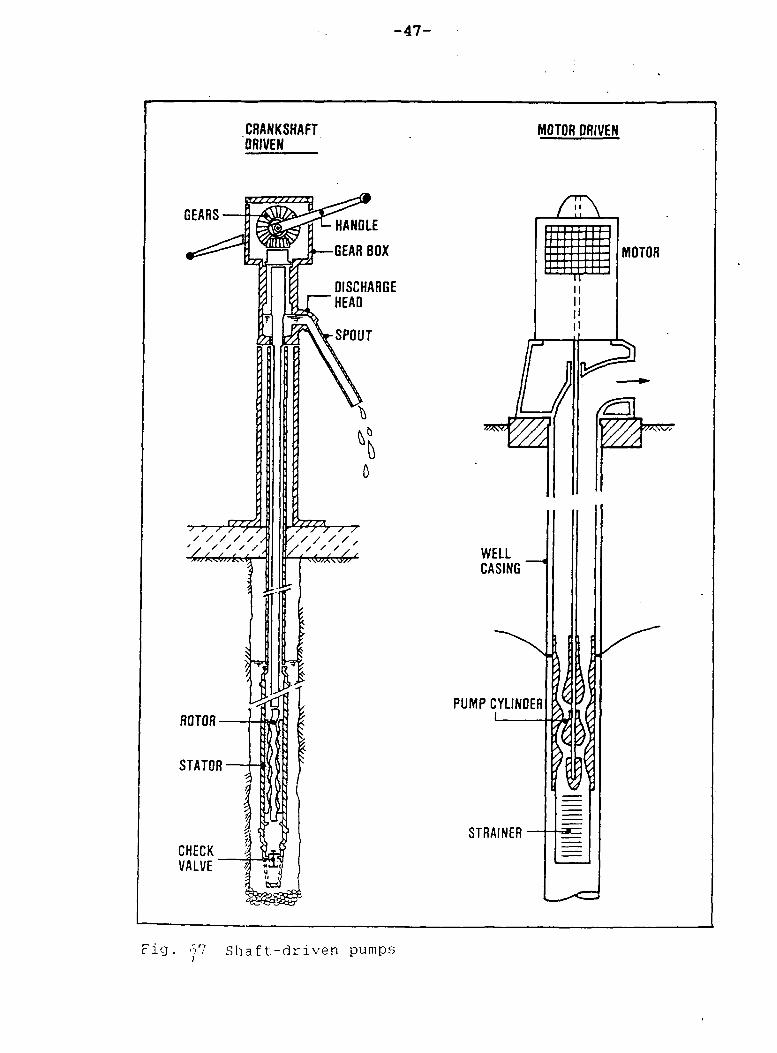
Similarly a shaft driven pump has been represented in Figure 67. Here crankshaft or motor is placed at the ground surface and powers the pump using a vertical drive shaft or spindle.
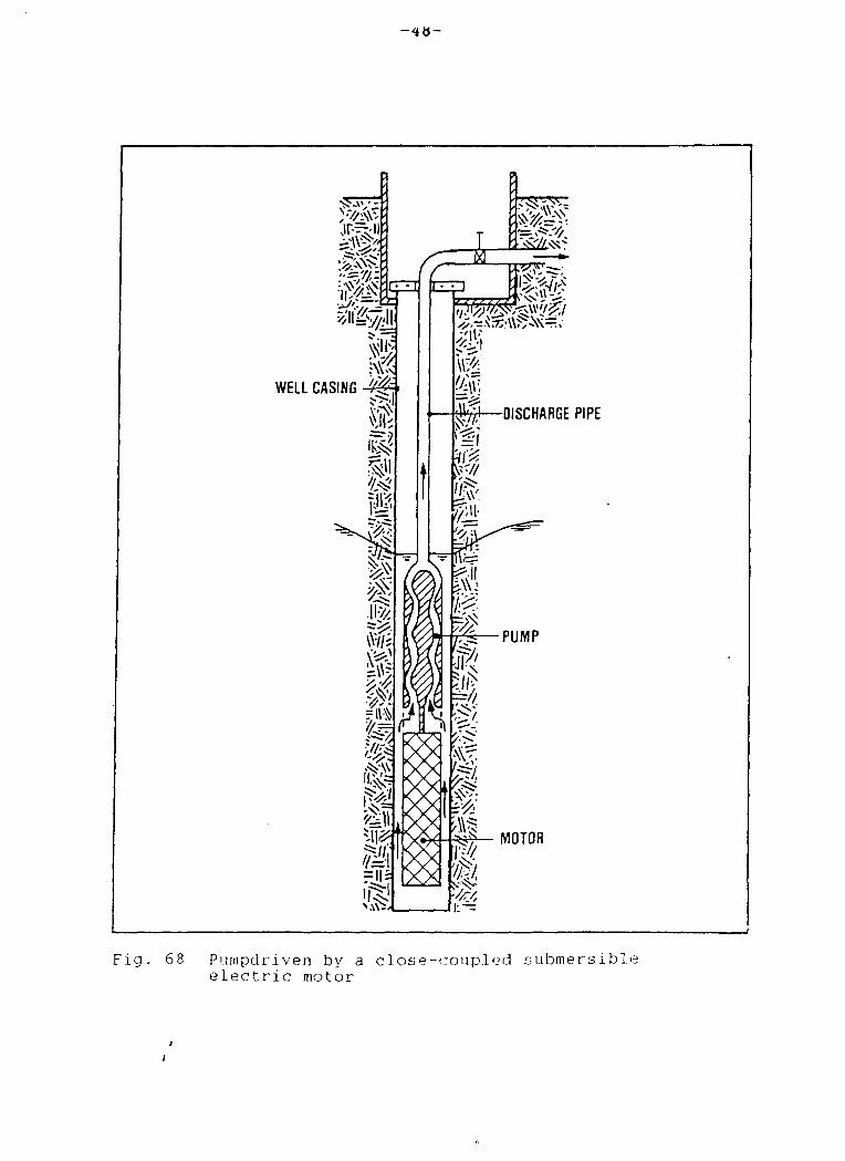
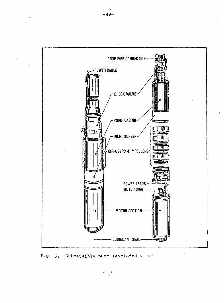
Figure 68 is an example of a centrifugal pump that is connected directly to an electric motor in a common housing with a pump and motor as a single unit and Figure 69 represents the exploded view of the submersible pump.
- 4 7 -
CRANKSHAFT DRIVEN
MOTOR ORIVEN
GEARS-
^
•7-7—r / / / / /
1
ROTOR -
STATOR•
HANDLE
-GEAR BOX
DISCHARGE HEAD
SPOUT
7 / / , / / / / , \/ / ' ' /
CHECK VALVE
ZiL\
WELL CASING
PUMP CYLINDER
STRAINER
MOTOR
F i g Shaft-driven pumps
- 4 8 -
WELL CASING-4#=>
± zi
^,-.^.-7;.>\\ft-i\\= ^
-DISCHARGE PIPE
MOTOR
Fig. 68 Pumpdriven by a close-coupled submersible electric motor
- 4 9 -
DROP PIPE CONNECTION
POWER CABLE
CHECK VALVE
A DIFFUSERS & IMPELLERS^
Szsmnc&&
PUMP CASING-
INLET SCREEN-
f[ W J
| f i' illll i!l
POWER LEADS-MOTOR SHAFT-
MOTOR SECTION •
LUBRICANT SEAL-
Fig. 69 Submersible pump (exploded view)
-50-
V. Aeration and Chlorination
1. Aeration: It is a treatment process whereby the water is brought into intimate contact with air with the objectives of: (i) increasing the oxygen content (ii) reducing the CO2 content, and (iii) removing hydrogen sulfide, methane and various volatile or organic compounds and ( iv) treating water which contains high iron and manganese.
Figure 70 provides a very simple and inexpensive arrangement of the multiple tray aerator which occupies little space. This type of aerator consists of 4 to 8 trays with perforated bottoms at intervals of 30 to 50 cm. Such trays can be made of any suitable material, like asbestos cement plates with holes, small diameter plastic pipes or parallel wooden slates.
Similarly, Figure 71 depicts a cascade aerator with similar features which consists of a flight of 4 to 6 steps, each about 30 cm high with a capacity of about 0. 01 m3 / s per meter of width. This aerator needs larger space than that for the tray aerator. But the overall head loss is lower in case of a cascade aerator.
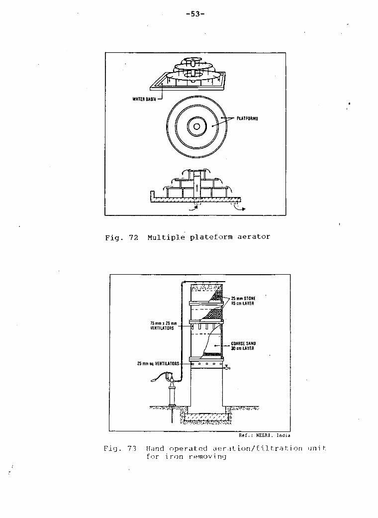
A multiple platform aerator also uses the same principles, sheets of falling water are formed for full exposure of the water to the air as shown in Figure 72.
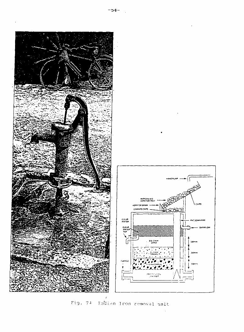
A hand-operated aeration/ filtration unit for the treatment of water having iron and manganese is shown in Figure 73.
Similarly, Figure 71 represents a section through the iron removal plant which has been widely used in the state of Orissa i n Indi a.
2. Chlori nati on: Disinfection of water provides for the destruction or complete inactivation of harmful microorganisms present in the water. In rural water supply, chlorination (use of chlorine as chemical disinfectant)is the simplest means of disinfection. However, disinfection by gaseous chlorine is not feasible for small community water supply as it is difficult to use small quantities of chlorine gas accurately and on a continuous basis. So the use of its compounds like bleaching powder or chlorinated lime is recommended.
Some simple chlorination methods for the disinfection of dug welIs are:
(i) Pot Chlorinator is an earthern pot of 7 to 10 litre capacity with 6 to 8 mm diameter holes at the bottom. It is half filled with pebbles and pea gravel (20 to 49 mm size). Bleaching powder and sand (1:2 ratio) is placed on the top of the pea gravel and the neck (Figure 75a). The pot is then lowered into the well with its mouth open. For a well of 1000 to 2000 litre/day withdrawl capacity, a pot containing 1.5 Kg of bleaching powder should provide adequate chlorination for a week.

-51-
(iij Double-Chlorination Pot System is a unit consisting of two cylindrical pots one inside the other used for chlorination of small household wells as the single pot chlorinator may give too high a chlorine content to the water. Figure 75b is an example of the double pot chlorinator.
(iii) Drip Type Chlorinator (Figure 75c)is another type of chlorinator which is also used for disinfection of deep wells.

52-
RAW WATER
AERATEO WATER
Fig. 70 Multilpe-tray aerator
\ N M I ' S : RAW WATER ) • >V J ; J '•'• X ;• '///J///. N\
AERATED WATER
Figure 12.4. Cascade aerator
Fig. 7] Cascade aerator
- 5 3 -
WATER BASIN - 1
B (^t^
PLATFORMS
h V_>
Fig. 72 Multiple plateform aerator
&]&
75 mm x 25 mm VENTILATORS
25 mm tq. VENTILATORS
^V
> 25 mm STONE 15 cm LAYER
COARSE SANO " 30 em LAYER
o o a o o
w.vv;v.'AWs^.d
A
siv^-i1;-*;-
Ref.: NEERI. India
Fig. 73 Hcind operated aer.it ion/Til tra t.i on unit Cor i ron remov i ng

-55-
J
7 HOLES (as CM orAi*"^
r l S S E ^ " ^ PEBBLES 'i 'pooB^'^v
1V"-. ' .V^' 'T . r '"-?\V_IL POWDER
' M.'r. ^: ~"^?-\i 'mo
^ | M ^ ^ ^ — P E A GRAVEL
&QS&5&' PEBBLES
' Fig. 75 * a' Chlorination pot with holes
at the bottom
PLASTIC OR EARTHEN JAR
m BLEACHINB POWOER a SAND
After: Raiaeopalan & Shiffman
Fig. 75 ' b ' Double pot chlor ina tor
COVER
SIEVE- f*l DIIDDtD \
i | £
FLOAT
w
L RUBBER STOPPER
PLASTIC CAP
/
RUBBER STOPfER
1 —6LASS-TEE
RUBBER-HOSE
COVER
- PLASTIC JERRYCAN-I
Fig. 75 xc' Equipment Cor feeding chlorine solution
-56-
References
A. C. THORT. F M LAW and F M CROWLEY (1985). Hater Supply, Edward Arnold, pp. 425, 426
B. C. PUNMIA ( 1 977) . Environmental Engineering (volume 1), Water Supply Engineering, Standard Book House, Delhi, pp. 396
Developing World Water (1987). Grosvenor Press International Ltd., West Garden Place, London , pp. 218
Hand pumps (1977). Technical Paper Series 10, International Reference Centre for Community Water Supply, The Hague, The Netherlands, pp. 41-42, 131-134, 147-148
H.P. BANZIGER (1982). Hand/ Foot Pumps for Village Water Supply in Developing Countries, Part II - Description ofpump types, VambuelstraBe 14, CH - 9000 St. Gallen, Switzerland, pp. 5, 7, 30, 35
Small Community Water Supplies (1981). Technical paper Series 18, International Reference Centre for Community Water Supplies, The Hague, The Netherlands, pp. 59-71, 100-129, 137-143, 167-182, 201-205, 299-307