sm1008 computerised diagram · thin circular plates are frequently encountered in engineering...
TRANSCRIPT

SM1008Computerised
Diagram
C> TQ Education and Training LId 2000No part of this publication may be reproduced or transmitted inany form or by any means, electronic or mechanical, includingphotocopy, recording or any information storage and retrievalsystem without the express permission of TQ Education andTraining limited.
All due care has been taken to ensure that the contents of thismanual are accurate and up to date. However, if any errors arediscovered please inform TQ so the problem may be rectified.
A Packing Contents list is supplied with the equipment.Carefully check the contents of the package(s) against the list. Ifany items are missing or damaged, contact your local TQ agentor TQ immediately.
TQ Education and Training LtdProducts DivisionCH/PS/AJP/1195

TECQUIPMENT SMlOO8 COMPUTERISED CIRCULAR DIAPHRAGM
SEcnON 1.0 INTRODUCTION
Figure 1.1 SM1008 Computerised Circtllar Diaphragm Apparatus

TECQUIPMENT SMIOOS COMPUTERISED CIRCULAR DIAPHRAGM
Thin circular plates are frequently encountered in engineering practice.
Typical examples include diaphragms in control units and recorders, cylindercovers and sealing plates, and the flat ends of cylindrical pressure vessels andstorage tanks.
Such plates are subjected to lateral pressure which causes the plates to deflect.The outside edges may be fully clamped, which restricts the edge slope tozero whilst inducing edge bending moments, or may be simply supported,which produces zero edge bending moments accompanied by edge slopes.Practical situations usually give rise to imperfect clamping of the edges,where edge bending moments and slopes occur simultaneously.
The theory which is developed in this manual can be used to calculate plate
displacements, slopes, curvatures, and surface stresses and strains for anycircular plate of uniform thickness whose loading and support conditions aresymmetrical about the central axis.
The theory is used to predict the deflections and surface strains in adiaphragm with clamped edge conditions, carrying a uniform lateralpressure. The SMIOO8 Computerised Circular Diaphragm Apparatus isdesigned to permit accurate measurement of these quantities for directcomparison with the theory.

TECQUIPMENT SM1OO8 COMPUTERISED CIRCULAR DIAPHRAGM
SECTION 2.0 DESCRIPTION OF THE APPARATUS
Figure 2.1 Components of the SM1008 Apparatus
TECQUIPMENT SM1008 COMPUTERISED aRCULAR DIAPHRAGM
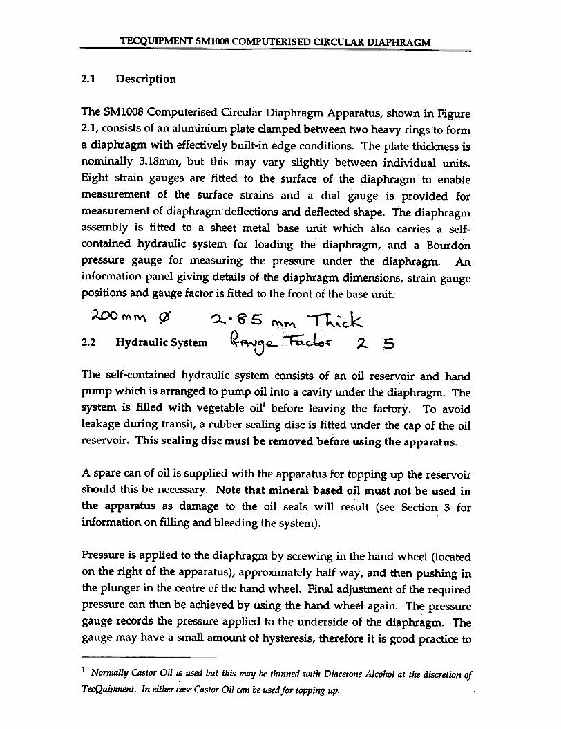
2.1 Description
The SM1008 Computerised Circular Diaphragm Apparatus, shown in Figure2.1, consists of an aluminium plate clamped between two heavy rings to forma diaphragm with effectively built-in edge conditions. The plate thickness isnominally 3.18mm, but this may vary slightly between individual units.Eight strain gauges are fitted to the surface of the diaphragm to enablemeasurement of the surface strains and a dial gauge is provided formeasurement of diaphragm deflections and deflected shape. The diaphragmassembly is fitted to a sheet metal base unit which also carries a self-contained hydraulic system for loading the diaphragm, and a Bourdonpressure gauge for measuring the pressure under the diaphragm. Aninformation panel giving details of the diaphragm dimensions, strain gaugepositions and gauge factor is fitted to the front of the base unit.
~M1\-'\ ~ ~M --l~~~'- ..~~ ~
~.~5
~Q2.2 ~Hydraulic System 5
The self-contained hydraulic system consists of an oil reservoir and handpump which is arranged to pump oil into a cavity under the diaphragm. Thesystem is filled with vegetable oill before leaving the factory. To avoidleakage during transit, a rubber sealing disc is fitted under the cap of the oilreservoir. This sealing disc must be removed before using the apparatus.
A spare can of oil is supplied with the apparatus for topping up the reservoirshould this be necessary. Note that mineral based oil must not be used inthe apparatus as damage to the oil seals will result (see Section 3 forinformation on filling and bleeding the system).
Pressure is applied to the diaphragm by screwing in the hand wheel (locatedon the right of the apparatus), approximately half way, and then pushing inthe plunger in the centre of the hand wheel. Final adjustment of the requiredpressure can then be achieved by using the hand wheel again. The pressuregauge records the pressure applied to the underside of the diaphragm. Thegauge may have a small amount of hysteresis, therefore it is good praCtice to
I Nonnally Castor Oil is used but this may be thinned with Diacetone Alcohol at the discretiOn of
TecQuipment. In either case Castor Oil can be used for topping up.

TECQUIPMENT SMlOO8 COMPUTERISED CIRCULAR DIAPHRAGM
gently tap the gauge before taking precise readings of pressure. The normalmaximum working pressure of the apparatus is 75kN/m2 and this pressureshould not be exceeded.
Strain Gauges2.3
Figure 2.2 Positioning of Strain Gauges
Eight electrical resistance strain gauges are fitted to a segment of thediaphragm as shown in Figure 2.2. Three pairs of gauges (1 and 2, 3 and 4, 6and 7) allow measurement of the radial and circumferential strains at threeradial positions. An additional radial gauge (gauge 5) is fitted at thetheoretical point of zero radial strain (r /R = 0.577). The last gauge (gauge 8)
is fitted at the same radius as gauges 6 and 7 (r /R = 0.9) but is placed at 45° to
the radial direction. This gauge provides an additional reading whichenables the student to confirm that the surface strain at 45° is midwaybetween the principal values in the radial and circumferential directions.

TECQUIPMENT SM1008 COMPUTERISED CIRCULAR DIAPHRAGM
2.4 Deflection Measurement
The gauge carrier assembly consists of two 'L' shaped brackets which locateonto the upper clamping ring of the diaphragm assembly. A cross beam isclamped onto these brackets. The digital vernier scale, for reading the radialposition on the crossbeami and dial gauge assembly fits onto the cross-beamof the carrier and can be traversed across a diameter of the diaphragm bysliding it along the beam.

TECQUIPM~T SMIOO8 COMP~:!ERISED CIRCULAR DIAP_~GM
SECllON 3.0 COMMISSIONING THE APPARATUS
The system is despatched fully assembled and pre-filled with vegetable oiland almost ready for use. Inside the oil reservoir is a rubber sealing disc to
prevent leaking during transit which should be removed. The apparatusneed only be connected to a suitable mains supply and a PC, and the softwareinstalled, as detailed in the following sections.
WARNINGnns APPARATUS MUST BE EARTHBD
IMPORTANTThe wires in the mains lead supplied with the equipment are coloured inaccordance with the following code:
EARTH (E or -#-)
LIVE (L)
NEUTRAL (N)
GREEN-AND- YELLOW:
BROWN:
BLUE:
The mains lead supplied with this apparatus has either a US style plug orbare ends for connection to the supply. An alternative form of plug may befitted to suit local supply requirements. This plug does not need to be fusedas the apparatus contains its own protection arrangements, but if a fused plugis fitted, it should contain a 3A fuse of a type appropriate for the plug. To fitthe plug follow the instructions supplied with it whilst observing the colourcode above.

The3.1.
3.1 Connecting the SM1OO8 to a PC
IRC-
ection req
Figure 3.1 Connection Diagram For The SM1008 & PC
(r
ents for the SM1OO8 and the PC are shown in Figure
IJ
n
-~J..4.
0
c..
~00
FCU
~;,(,
-
~ §o
~
~Z0-~a
~~U~Uawtn~
50-~0u~00-~tn

TECQUIPMENT SMl!~8 COMPUTERISED CIR~ DIAPHRAGM
The 9-way connector of the lead supplied with the SMIOO8 should beplugged into a serial port on the computer. The port used may be COM!,COM2, COM3 or COM4. A mouse is not necessary to operate the software,so if your computer has only one port and this is used by the mouse,disconnect it and use this as the SMIOO8 port. If you are using a mouse orsome other device that uses serial port interrupts then care should be taken toensure that the SMlOO8 and the device do not try to use the same iriterrupt.Ports COM! and COM3 both use interrupt IRQ4 and COM2 and COM4both use interrupt IRQ3. If your mouse/device is using COM1/COM3 thenuse COM2 or COM4 for the SMIOO8 and, similarly, if the mouse/device isusing COM2/COM4 then use COM! or COM3 for the SMIOO8.
If your computer has a 25-way serial port, use a fu1l25 to9-way female/maleadapter lead.
Beware of using a 25 to 9-way adapter supplied with a mousebecause it may not connect all the necessary lines.
Switch on the SMIO08 and the computer. The green LED on the front of theSMIOO8 beside the 9 pin serial port will light when the SMIOO8 is on.
3.2 Installing Software onto a PC
Additional copies are available from:
TecQuipment Ltd
Bonsall Street
Long Eaton
NottinghamNG1O 2AN
UNITED KINGDOM.

~CQUIPMENT SMIOO8 ~OMPUTERISED C~gLAR DIAPHRAGM
The software is supplied on a 3.5 inch, 720K disk.required contact TecQuipment for replacements.
If other formats are
The installation routine takes the source drive that you are installing fromand the destination drive that you are installing to as parameters, i.e.INSTALL <SOURCE DRIVE> <I?EST DRIVE>. For example, to install from
o. ..
Drive A to drive C type,
A: INSTALL A: C:<Enter>
If Drive B is used, then type,
B: INSTALL B: C:<Enter>
If you are installing to a network drive you might type,
A:INSTALL A: N:<Enter>
Assuming N: was the network drive you wanted to use.
Alternatively, if you want to install the software to a subdirectory of anexisting directory you can install using: INSTALL <SOURCE DRIVE> <DESTPATH>. For example to install from A: to an existing directory, C:\TQ, youwould type the following:
A:INSTALLA: C:\TQ
The installation batch me will create a sub-directory called 'SM1OO8' in theroot directory or specified path of the specified destination drive. No filesoutside this directory will be affected. If the directory does not already existit will be created. All of the relevant files will be copied into this directory. Itwill then create a further sub-directory called 'DATA' which will be thedefault directory to store data files in. If an earlier version of the softwareexists it will be overwritten.
The final stage of the installation procedure adds the directory

TECQUIPMENT SMIOO8 COMPUTERISED CIRCULAR DIAPHRAGM
C: \SMIOO8;
(where C: is the destination drive you supplied on installation)
to the PATH statement in your AUTOEXEC.BAT file so that SM1008.EXEmay be called from the root directory.
Alternatively, the program may be conveniently called by creating a batchfile which includes the lines
c:CD\SMIOO8SMIOO8
If additional information on file management is reqUired, the relevant DOSmanual should be consulted.
3.3 Maintenance
The SM1OO8 Computerised Circular Diaphragm Apparatus normally requireslittle maintenance. In order to maintain the appearance of the apparatus thesurfaces of the base module and diaphragm unit can be cleaned with asmooth cloth moistened in soapy water. The diaphragm should not becleaned other than by gently dusting.

:yECQUIPMENT ~~1008 COMPUTERISE~IRCULAR DIAPHRAGM
The hydraulic system is filled with oil prior to despatch from the factory and,apart from removing the rubber sealing disc in the oil reservoir, shouldrequire no further attention. Normally the oil level should be kept to within20mm of the top of the reservoir and a spare can of oil is provided with theapparatus for topping up. However, if for any reason the oil level in thereservoir becomes low, or if it is difficult to achieve the normal test pressureof 75kN/m2, it may be necessary to bleed the system to ensure that airbubbles are removed.
A bleeder rod isThe procedure for bleeding the system is as follows.provided with the apparatus to assist with this operation.
1. Ensure that the reservoir is ruled up to within 20mm of the top andreplace the cap.
2. Raise the left hand end of the apparatus and support it on a suitableblock or box so that it is inclined as shown in Figure 3.2. Leave theapparatus in this position for 1-2 hours, or overnight if possible, toallow any air bubbles to collect at the upper end of the apparatus.
3. Fully unscrew and remove the knob and threaded shaft from the handpump and replace with the bleeder rod.
4. Push a suitable length of hose over the bleed nipple and place theother end in a beaker (Figure 3.2).
5. Undo the bleed nipple by 1-2 turns.
6. Push the bleeder rod in until oil flows out of the bleed nipple. Repeatthe operation until all air bubbles have been removed.
7. Re-tighten the bleed nipple, remove the hose, replace the threadedshaft in the pump block and return the apparatus to the upright
position.
8. Check the oil level in the reservoir and top up as necessary.

TECQUIPMENT SMIOO8 COMPUTERISED CIRCULAR DIAPHRAGM
In the event of any problems developing with the oil seals in the hand pump,a replacement set can be supplied. Please contact TecQuipment for details.

TECQUIPMENT SMlOO8 COMPUTERISED aRCULAR-DIAPHRAGM
SECTION 4.0 THEORY
4.1 General Equations
Fi~e 4.1 shows a circular plate of uniform thickness deflected by the actionof a lateral pressure p. The plate supports are not shown. The deflection isgreatly exaggerated for clarity. Because the plate is loaded and supportedsymmetrically, it must deflect to a shape which is symmetrical about thevertical axis. Therefore, if we adopt a co-ordinate system, as defined inFigure 4.1{b) where r is the radius of any point and 9 is the angular positionof the radius defined in plan view, then all stresses, strains, displacementsand related quantities are independent of9.
If we measure the vertical distance within the plate from the mid-plane by z(positive upwards as indicated in the inset to Figure 4.1a), then the radialdisplacement of a point in the plate defined by rand z is given by zcj). Thisradial displacement is termed u, so
u=zcjI
where ~ is the slope of the plate at the radius r.
The vertical displacement of the plate from its initial unloaded position iscalled w, and is positive upwards. Using this, the slope of the plate, 4>, isrelated to wand r by the equation:
dwdr
cI>=
(4-2)
Note that the minus sign arises from the definition of (j) in Figure 4.1 where wis decreasing with increasing r.
In the following it is assumed that the plate deflections and slopes are small,so that the mid-plane of the plate is not stretched at any radius.

TECQUIPMENT SM1008 COMPUTERISED CIRCULAR-DIAPHRAGM
(a) Sectional view (deflection exaggerated for clarity)
---4--I"
~
/' '"/ "/ "//
/ '\\
- - -1-- -- --- - - - -.. - ~ :nOO#)U£o;9(U ",(1 10j. - - - ./ - - - ---~---r
I/
//
/
,\, \ "9 ~
'0'" /'-
~
I '- I ' 1-
--&--
(b) Plan view showing co-ordinate system
Figure 4.1

TECQUIPMENT SMlOO8 COMPUTERISED CIRCULAR-DIAPHRAGM
Figure 4.2 Strain of a Small Element above the Mid-plane (z>O)
To obtain the strains at any position within the plate, we recall that strain isdefined as the change in length divided by the ori~allength. For the radialstrain, an element of length or at radius r moves under load as shown inFigure 4.2. It's strain, 8r is given by:
(6r..6u) - 6rg =
~r
zdwdr
From Equations (4-1) and.(4-2); u = , so
d2w
dr2
dudr
& = = - z
(4-3)
The circumferential strain at any combination of rand z is found in a similarway. The circumference of a circle at radius r is 21U before loading and21t(r+u) after loading, so the circumferential strain, 8e, is given by:
.27t(r + u) - 27tr z dw---r'dr
ur£e = = =
21tf
(4-4)
Now the stress in the z direction, O'v is zero on one face of the plate and equalto -p (negative since it is compressive) on the other face. Also the radial andcircumferential stresses induced by plate bending tend to be much larger than

TECQUIPMENT SMlOO8 COMPUTERISED aRCULAR-DIAPHRAGM
p. It is therefore reasonable to assume that O'z is negligibly small throughout
the plate thickness.
Using this assumption, and denoting the radial and circumferential stressesby O'r and 0'8 respectively, we can write, from the general elastic stress-strain
relationship:
.!J;'B\~I8r =
(4-5)
-' 1:{ . "1£\0'8 -Be
-(4-6)
where E is Young's Modulus and v is Poisson's Ratio.
Eliminating 0'8 between Equations (4-5) and (4-6) leads to,
ERIo(8r +Y.88)0'.
-
(4-7)
and similarly I. eliminating or:
""'F{i-:7J(Se + vsr)0'8 =
d2w'~0'9
= -+vHz ( 1 dw
-R -; di:
(4-8)
Note that both stresses vary linearly with z and are zero on the mid-planewhere z = o.

TECQUIPMENT SM1008 COMPUTERISED CIRCULAR-DIAPHRAGM---
It is evident that if the plate displacement w can be determined as a functionof r, Equations (4-7) and (4-8) will give the radial and circumferential stresses,and these can be substituted into Equations (4-5) and (4-6) to give the
corresponding strains.
(Q + ~Q 8r) /'-ar-
_d~\~
"":0":1 0-~
.)(r~
'QJ~:
8!:.
~
Figure 4.3 Definition of Bending Moments for a Small Element
Figure 4.3 shows a small element of plate ABCD. The element size is verygreatly exaggerated. Referring to this figure, we now define Mr as the
bending moment associated with radial stresses and Me as the bendingmoment associated with circumferential stresses. Both Mr and Me are
expressed in terms of bending moment per unit width of plate. Note that Mrand Me do not vary with e because of symmetry, although both Mr and Me do
vary with r.

TECQUIP~ SM1008 COMPUTERISED CIRCULAR-DIAPHRAGM
- Unit Width
~.l
Figure 4.4 Basis for Calculation of Bending Moment in the Radial
Direction
Mr and Me can be related to O'r and 0'8, and hence tow, rand z, by considering
a small strip of unit width at height z from the mid-plane as shown in Figure4.4. The moment is equal to the sum of the moments due to the forces in eachstrip so, Mr and Me can be expressed as follows:
Mr ~
t-'
j £ZZ
t~~
d2w, ,
)d
rJi:2'+ ~W dz
3'"' d2 w
dr2+~~
)r drMr ~
Mror, = -D(~+;~)(4-9)

TEC~~~T SM1OO8 COMPUTERISED CIRCULAR-DIAPHRAGM
Et)Where D is the flexural rigidity equal to
Similarly, Me -
-D(;~+~JMeso, =
(4-10)
Consider now the element of plate length Sr , sub tending an angle f>e at the
plate centre as shown in Fi~e 4.3.
In addition to the moments acting on all four edges of the element, the edgesBC and AD must each carry a shear force. The shear force at the edge BC isinduced by the pressure applied to the plate over the segment OBC, whilstthat at the edge AD supports the pressure acting on the segment OAD. Thusthe shear force per unit width of plate, defined asQ, will vary with r. Therecan be no shear forces on the edges AB and CD because either of these edgescan be regarded as a plane of symmetry of the whole plate. Shear stresses
cannot exist on planes of symmetry.
The element ABCD must be in equilibrium under the combined action of itsexternal loading, so taking moments about the mid-tangent to BC, the
components of the moment equilibrium equation are:-
due to the moment on side CBMrrOO
dM .,
Mr + --LSrdr ..
due to the moment on side AD
~2
due to the moment on side AB, resolvedparallel to the mid-tangent to BC
Me 6r Sin
562
due to the moment on side CD, resolvedparallel to the mid-tangent to BC
Me Sr Sin
due to shear force on side AD

~CQUIPMENT SM~8 COMPUTERISED CIRCULAR-DIAPHRAGM
due to pressure acting on ABCDprM5r~ 2
These moment components must sum to zero for equilibrium, so
6rr~
0=
Expanding, and proceeding to the limit where 6e -+ 0,
'my;
'go---6r -+ 0, and Sin , the equation reduces to2
~
dM '.:Mr + r--L - Me +,Q,T
dr ' 0,=
(4-11)
Substituting the values of Mr and Me from Equations (4-9) and (4-10) intoEquation (4-11) and simplifying gives:
QD
-d3w 1 d2w .. 1 dw-+--+--dr3 r drz r dr
(4-12)
which can be written more conveniently as
ddr
!~r dr
~D
=
(4-13)
The equivalence of Equations (4~12) and (4~13) can bedifferentiating the left hand side of Equation (4-13).
checked by
Q is easily determined as a function of r, because at any radius r, the totalshear force on the circumference of the circle of radius r must equal the

~UIPMENT SM1OO8 C~MPUTERISED ~~-DIAPHRAG~
For example, if a pressure p is applied allpressure loading within the circle.
over the plate, then
P 7t r227trQ =
!£2andQ =
(4-14)
Equations (4-13) and (4-14) allow the determination of w,the plate deflection,in terms of r, p and D. The stresses and strains can then be determined
directly from Equations (4-5) and (4-8).
Diaphragm with Oamped Edges and Uniform Pressure Loading.4.2
The general theory developed in the previous section will now be applied tothe particular case of the SMIOO8 diaphragm. The outer radius of the
diaphragm is called~ its thickness t, and the applied pressure p.
Deflection
From Equations (4-13) and (4-14)
pr~'2D
=
(4-15)
This can be solved by successive integration.
Integrating both sides with respect to r,
~4D
1 d ( dW )-- r-
r dr dr~'C,=
(4-16)
where CI is a constant of integration which will be found from boundary
conditions.

~~~MENT SMl008 COMPUTERISED CIRCULAR-DIAPHRAGM
Multiplying by r,
dW
)drddr
pr3"'4i)"+ C, rt- =
(4-17)
Integrating again
dwdr
4 rPrC ~+r',-+ 1 ~~~ 2r =
16D
(4-18)
Dividing by r,
~ + '21:~2 r
dwdr
= -16D
(4-19)
We could integrate this equation again before considering boundaryconditions, but it is more convenient to recall here that
dwdr
- cI» Equation (4-2) and cI» is the plate slope.=
Putting
L16D
dwdr
r+c'i
=
(4-20)
dwdr
Also, because the edge clamping gives zero slope, we know that - 0-at r = ~ so from Equation (4-20),
pR3 ~+ 2{" pR23D
0 and C,= ~-rIm
Equation (4-20) becomes

TECQUIPMENT SM1OO8 COMPUTERISED CIRCULAR-DIAPHRAGM
dwdr
-~(4-21)
Integrating this gives
pR2r2Lw =
(4-22)
~ is found by using the boundary condition of zero deflection at t = R
4 R4pR- -..p.- + C,
32D0ie = -
64D
pR464D
Whence C3 =
The final deflection equation is therefore
-2Rzr+R4)w
~
(4-23)
Stresses
To find the stresses at the plate surface, the expression for w can besubstituted into Equations (4-7) and (4-8) in which z has been given its plate
surface value of ! (z has this value on the side of the plate which is not2
pressurised).
Differentiating Equation (4-21) gives
d2w
~= ~(3r2 -

TECQUIPMENT SMlOO8 COMPUTERISED CIRCULAR-DIAPHRAGM--
dwdr
and substituting this, together with from Equation (4-21) into Equations
(4-7) and (4-8) we get:
O'r =
(4-24)
and
a8 -
(4-25)
Strains
The surface strains at z = ..!. can be evaluated by substituting these2
expressions for O'r and 0'0 into Equations (4-S) and (4-6), giving:
3p (--" "SEt" 1 v )(R - 3r8, ~
(4-26)
and
88 =
(4-27)
It should be noted that the radial and circumferential strains are equal at theplate centre, where r = O. This must be so because we cannot distinguish
between the radial and circumferential directions of an element placed at r =O. A similar argument can be applied to the radial and circumferentialstresses (Equations (4-24) and (4-25», which must also correspond at r = O.
These are useful checks on the theoretical analysis.
Inspection of Equations (4-26) and (4-27) shows that the circumferential strainis zero at the clamped edge of the diaphragm, and rises to a maximum at the

TECQUIPMENT SM1008 COMPUTERISED CRCULAR-DIAPHRAGM
centre. The radial strain is positive (tensile) at the centre and negative(compressive) at the damped edge. The radial strain has a zero value whenR2 - 3i = 0, which is when r = 0.577R.
Seven of the eight strain gauges on the experimental apparatus are aligned inradial or circumferential directions, and Equations (4-26) and (4-27) give thetheoretical values of these strains for comparison. The eighth strain gaugebisects the radial and tangential directions, so it is also necessary to determinethe theoretical strain in that direction.
It can be shown that the direct strain in a direction inclined at a to the radialdirection is given by:
~(£r + £.)-~(£8 - £r )Cos2a.8~ =
(4-28)
As a check on the validity of this equation, it is evident that the substitution ofa. = 00 and 900 will lead to So = Sf and S90 = £e. These are entirely consistent
with the definition of a..
Equation (4-28) forms the basis of the Mohr strain circle and it should benoted that to find &a we use the angle 2a..
When the strain gauge bisects the radial and tangential directions, a. = 45°,and Equation (4-28) gives:
~&r + &8)t:4S =
(4-29)
which is the required theoretical relationship.

TECQUIPMENT SMlOO8 COMPUTERISED CIRCULAR DIAPHRAGM
5.0 SOFTWARE OPERATION
The program requires at least 450K base memory free to operate. To start theprogram it will be necessary run the SM1008.EXE file by typing,
SMIOO8<Enter>
The installation routine described in Section 3.2 will have ensured that thisfile is located in the directory,
C:\SMIOO8
Where C: is the destination drive supplied on installation
If you are unfamiliar with DOS and how to run files from differentdirectories, the command
C:\SMIOO8\SMIOO8<Enter>
will find it. For further information on handling and loading files it isrecommended that the relevant DOS manual is consulted.
When the title page appears, press <SPACE> to show the Main Menu screen.The package operates in 'drop down menu' fashion common to modemsoftware. A typical screen is shown in Figure 5.1.
The current position on the menu tree is highlighted with white text on a redbackground, indicating the cursor. When first entering the software, thecursor will be placed in the top left-hand hand corner on the File option.Pressing the cursor 'Left' and 'Right' keys moves the cursor along the top ofthe menu structure. Pressing <ENTER> or holding down the <Alt> key andpressing the letter that is underlined on a menu item will show the contentsof that particular menu. These appear as a drop-down list of functionsand/ or parameters. Alternatively the mouse can be used to select menus andmenu items.

TECQUIPMENT SM1008 COMPUTERISED CIRCULAR DIAPHRAGM
Use the cursor 'Up' and 'Down' keys to highlight an item in this list and then<ENTER> to select it, or press the letter underlined on the option. Anextended description of the item appears at the bottom of the screen. Formore detailed information on the menu items press F1 to activate the context-sensitive help.
When selecting an item the menu could behave in a number of ways:
L Show a sub-menu. If a menu item is followed by an ellipsis (...) then asub menu will appear and another option has to be selected.Alternatively I pressing <Escape> will move back up one level of themenu tree.
2. Prompt for a number to be entered. A box will appear giving theallowable limits of the number to be entered and the default value willappear highlighted. Use any of the editing keys to edit this value,press any other key to overwrite the value. Pressing <Escape> at anytime will return to the menu without altering the default value.
3. Prompt for text to be entered. As with number entry the default textcan be edited or overwritten.
Toggle an option on and off. If a menu item is preceded by a smallsquare, pressing <Enter> will toggle the option on and off. If anoption is on the square will have a tick in it.
4.
5. Display a pick list of possible options. When a menu has circlesbefore every item then only one item may be selected at anyone timeand the currently selected item has the circle filled. Select one of theoptions on the list using the cursor keys and pressing <Enter>,pressing <Escape> at any time will return to the previous menu.
6. Execute the menu option. If the option has no parameter attached anddoes not have a sub-menu then selecting it will execute the option.

TECQUIPMENT SMlOO8 COMPUTERISED CIRCULAR DIAPHRAGM
Figure 5.1 A Typical 'Drop Down' Menu Screen
5.1 Testing Communications
This test is important, especially when commissioning the unit for the firsttime, or when difficulties are experienced in communicating between theSM1OO8 and the host PC running the SM1OO8 software. In the latter case, thiswill become known when the SMIOO8 software displays the screen message:
"Error. Unable To Communicate With The SMIOO8. Press ESC."
If communications between the SMIOOB software and the SMIOOB are made
then the computer displays the message:
"SMIOO8 Communications OK. Press ESc."
At the Main Menu screen, use the 'Left' and 'Right' cursor keys to select the
Options Menu. The options menu is only available if the setup switch has been
used on the command line, i.e. the software was started by typing SMIOO8 /5. Press
<ENTER> to produce the drop-down list of available options.
Select the serial port that you are using by highlighting Serial port on theoptions menu, pressing <Enter>, highlighting the port to use and pressing<Enter> again.

TECQUIP~SMl008 COMPUTERISED CIRCULAR DIAPHRAGM
With the required port selected, select the option 'SMIOO8 Interface Test' andpress <Enter>.
If the error message is displayed, check the leads, power supply and COMPort selection. Press <ESCAPE> and then <ENTER> to try again.
5.2 Running as Virtual Instrumentation
The SMIOO8 software can be used as virtual instrumentation for thediaphragm apparatus. To use this facility simply select the Run option fromthe main menu.
5.3 Menu Options Guide
As described previously the software operates in a 'drop down menus' stylewith each menu having a number of possible options. The function of eachmenu option is as follows: .
5.3.1 The File Menu
Use the file menu to load and save data files and to exit from the software.
The data from an experiment can be stored on a hard disk or floppy disk.This is done by selecting the File/Save menu option. This prompts the user toenter a filename with or without a path name as shown in Fi~e 5.2. Do notenter filenames with a suffix as all data files automatically have the suffix. TQD appended to them. The top box is for text entry of a filename via thekeyboard, the left box allows a file to be selected from a list of the filesavailable in the selected directory, the top right box allows selection of theparent directory (..) or any sub-directories and the bottom right box allowsselection of a different drive. Use the Tab key to move the highlight frombox to box and use the up and down cursor keys to select an item in a box.Alternatively the mouse may be used to select the required filename and pathusing the scroll bars to the right of the list boxes to move through the lists.

TECQUIPMENT SMl008 COMPUTElUSED CIRCULAR DIAPHRAGMc.=
Similarly, data can be re-loaded into the software using the File/Load menu
option.
Figure 5.2 File Selection Box
The data files are stored in a text format.discussed in Section 8.
The format of the data on disk is
LoadThe Load command is used to retrieve data from a previous experiment. Theuser is prompted for a file and/ or a path name with the file list box describedabove.
Save
The Save command is used to save data from an experiment for future use.The user is prompted for a file and/or path name with the me list boxdescribed above. The file is saved in an ASCII format compatible with manyspreadsheet and analysis packages.
ExitThe exit command is used to quit the SMIOO8 software package.recorded data will be lost if it has not already been saved.
Any

TECQUIPMENT SMl008 COMPUTERISED CIRCULAR DIAPHRAGM
The Tutorial Menu
There is a short tutorial included in the software. This includes definitions ofthe various stresses and strains present on a diaphragm, the theory behindthe diaphragm and a brief description of the diaphragm experiments. Therelevant experiment section of the tutorial can be brought up while anexperiment is running by pressing F9 (Tutor). The keys used to navigateabout the tutorial are:
FI-Help Brings up help on how to~e the tutorial.
Home Returns to the first page of the current tutorial section.
Page Up Displays the previous page (if any) of the current section ofthe tutorial.
Page Down Displays the next page {if any) of the current section of thetutorial.
Jumps to the last page of the current tutorial section.
F1O-Menu Exits from the tutorial and returns to the menu system or the
experiment being performed.
Figure 5.3 Typical Tutorial Page

~~QUIPMENT SMlOO8 COMPUTERISED CIRCULAR DIAPHRAGM
5.3.3 The Run Option
The SMIOO8 software can be used as a virtual instrument to display the
pressure and strains present on the Diaphragm. To use this mode select the
Run option on the main menu. ASsuming the SMIOOB is connected correctly
the current values of strain and pressure will be displayed on the screen.
The main feature of the screen is a graphical representation of the Diaphragm
complete with pressure gauge and strain gauges. The screw to the left of the
cylinder indicates the position that the adjustment. screw should be in for the
experiment being performed.
The pressure is displayed both as a number and on a representation of apressure meter. Above the pressure meter are two virtual LED's, the first,labelled Update, blinks green every time the pressure and strain readings areupdated in time with the green LED on the front of the SM1OO8 apparatusand indicates correct communication with the SM1OO8. The second 'LED',labelled Hold, flashes low and high intensity yellow while the readings arebeing held after F5 has been pressed.
Figure 5.4 The SMIOO8 Screen with the IRunl Option Selected.

TECQUIPMENT SMl008 COMPUTERISED CIRCULAR DIAPHRAGM
The following keys are available while running as virtual instrumentation:
FI-Help Pressing the FI key will bring up a help box that describesthe operation of the other function keys. Press any key toremove the help box.
F4-Zero Pressing the F4 key will zero all of the pressure and strainreadings. This should always be done, with no pressure onthe system, after the equipment has had a chance to warm upand before any readings are taken.
F5-Hold Pressing the FS key will 'freeze' the screen and hold thecurrent values. This option can be used to assist in the takingof manual readings. Pressing any key will reswne normal
running
Pressing the FIO key will stop the controller and return thescreen display to the main menu.
FIO-Menu
The Experiment Menu5.3.4
The experiment menu allows the user to create the tables and graphsdescribed in the Experimental Section and is described in detail in Section 6.0.
5.3.5 The Options Menu
Use the options menu to set your hardware configuration, check the seriallink with the SMIOO8 and save or load configurations. Normally the optionsmenu is disabled as setting up is normally only required on initial installationof the apparatus. Access to the options menu is achieved by starting thesoftware with the /5 switch on the command line, i.e. starting the software by
typing SMIOOB /5.

TECQUIPMENT SM1008 COMPUTERISED CIRCULAR DIAPHRAGM
Gauge factorThis command is used to set the gauge factor of the strain gauges being used.This can be found on the front panel of the apparatus and must be entered foraccurate strain measurement to be possible.
Diaphragm thicknessThis command is used to set the thiCkness, in mm, of the diaphragm on theapparatus. This can be found on the front panel of the apparatus and must beentered for accurate results to be possible.
Serial portThis command is used to select the serial port, COMl to COM4, to be used forcommunication with the SMlOO8. Once this has been set the communicationscan be tested using the Test SMlOO8 Interface command. See Section 5.1 formore details on this command.
Serial interruptThis command is used to select the serial interrupt to be used for the selectedserial port. Normally this would be left at DEFAULT but it can be set to theappropriate interrupt number if required. The interrupt lines available are 2to 5 and 7. The default interrupts are IRQ4 for COM! and COM3, IRQ3 forCOM2 and COM4.
Test SMIOO8 interfaceThe Test SM1008 interface command is used to test the interface between thePC and the SM1008. The user will be prompted with a message indicatingthe state of the communications. Section 5.1 describes this procedure.
Printer portThis command is used to select the port to which printer output will be sent.The data can be printed using the File/Print command. Copies of the screencan be obtained by pressing the Print Screen key.
Printer typeSelect the type of printer to be used. The available printers represent aselection that virhla1ly all printers will be able to emulate. If you have ascreen capture or screen dump utility that you want to use instead of the

TECQUIPMENT SMlOO8 COMPUTERISED CIRCULAR DIAPHRAGM
default drivers then load your utility before starting the software and set theprinter type to 'No printer'.
Save configurationSave the current configuration to disk. Information stored includes: serial
port; printer port; printer type; gauge factor and location of directory for datafiles. This configuration will automatically be used the next time the softwareis loaded.
5.3.6 The Help Menu
Use the help menu to allow access to the help file and show copyright andversion information.
Help indexBrings up a pick list and allows selection of different help topics.
AboutDisplays version and copyright information.
TECQUIPMENT SM1OO8 COMPUTERISED CIRCULAR DIAPHRAGM
SEcnON 6.0 EXPERIMENTAL PROCEDURE AND RESULTS
Experiments with the SMIOO8 Computerised Circular Diaphragm Apparatuswill usually cover two aspects relating to diaphragms under pressure,
namely:-
(i)
(ii)
Measurement of deflections and deflected shape of the diaphragm,and comparison with theory.Measurement of surface strains and comparison with theory.
The SMIOO8 Diaphragm Software does not in itself attempt to teach straintheory, this is covered amply in Section 4.
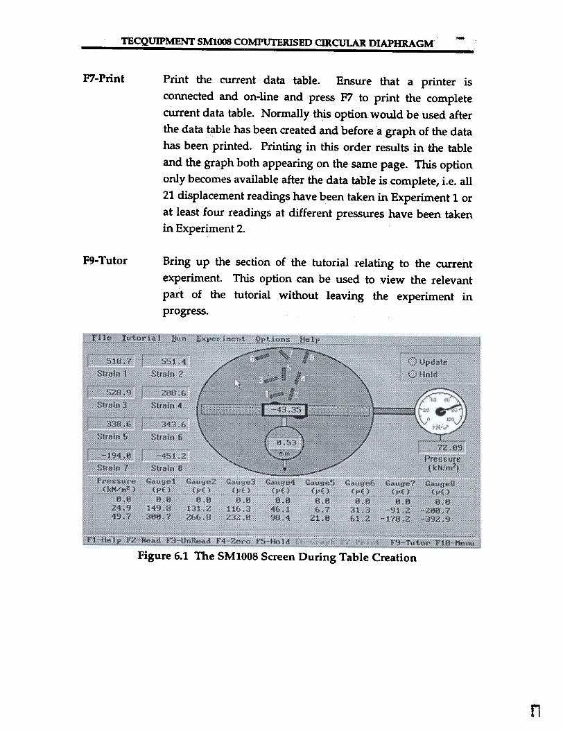
During Experiments 1 to 3 the screen appears in a similar form to Figure 6.1below and is the same as the screen described for the Run option with theaddition of a table below the representation of the diaphragm. The functionkeys available additional to those for the Run option are as follows:
F2-Read Copy the pressure and strain readings currently on screen tothe data table. Allow two seconds to let the pressure andstrains stabilise after any change in pressure before taking a
reading.
F3-Unread Remove the last reading taken from the data table.relevant to Experiments 1 and 2.
Only
F6-Graph Create a graph based on the current data table. ForExperiment 1 a graph of non-dimensional displacement ofthe diaphragm under pressure is shown, Experiment 2 resultsin a graph of strain against pressure and Experiment 3 gives agraph of experimental and theoretical strain gradients. Thisoption only becomes available after the data table iscomplete, i.e. all 21 displacement readings have been taken inExperiment 1 or at least four readings at different pressureshave been taken in Experiment 2.
Page 6-1
-TECQUIPMENT SMlOO8 COMPUTERISED CIRCULAR DIAPHRAGM-- - -- -- --- -
F7-Print Print the current data table. Ensure that a printer isconnected and on-line and press F7 to print the completecurrent data table. Normally this option would be used afterthe data table has been created and before a graph of the datahas been printed. Printing in this order results in the tableand the graph both appearing on the same page. This optiononly becomes available after the data table is complete, i.e. all21 displacement readings have been taken in Experiment 1 orat least four readings at different pressures have been takenin Experiment 2.
F9- Tutor Bring up the section of the tutorial relating to the currentexperiment. This option can be used to view the relevantpart of the tutorial without leaving the experiment in
progress.
Figure 6.1 The SM1008 Screen During Table Creation
n

TECQUIPMENT SM1008 COMPUTERISED CIRCULAR DIAPHRAGM-~ - - -
Deflected Shape6.2 Experiment 1:
Select this option to create Table 6.1 and display and print a graph showingtheoretical and experimental deflection profiles for the diaphragm under
pressure.
The following steps should be taken:
. Ensure the cylinder is at zero pressure by checking that the hand
wheel turns freely and the pressure gauge reads zero.. Press F4 to zero the pressure and strain signals.. Increase the pressure to, say, 75kN/m2.. As in the surface flatness measurement preparation you will be
required to position the traverse gauge at a specific reading andpress F2 to measure the deflection at that point. Press F3 to removeunwanted readings.
. Once all 21 deflection readings have been taken options F6-Graph
and F7-Print become available.. Press F7 to print the complete data table.. Press F6 to show a graph of measured strain against pressure. The
software automatically performs a least squares, best straight line fitto the experimental data points and displays the resulting gradientson the graph. These gradients are used in Experiment 3 and so thegraph must be displayed before Experiment 3 can be performed.
. Press F10 to return to the experiment and F10 again to return to the
menus.

TECQUIPMENT SMIOO8 COMPUTERISED CIRCULAR DIAPHRAGM
6.3 Experiment 2: Surface Strains
Select this option to create Table 6.2 and display and print a graph showingthe variation of strain with applied pressure.
The following steps should be taken:
. Ensure the cylinder is at zero pressure by checking that the hand
wheel turns freely and the pressure gauge reads zero.. Press F4 to zero the pressure and strain signals.. Press F2 to take a strain reading at zero pressure.. Increase the pressure by, say, 25kN/m2 at a time allowing a couple
of seconds at each new pressure (to allow the various transducerreadings to settle) before pressing F2 to take a reading. Press F3 toremove the most recent reading if desired.
. Once at least 4 readings have been taken the options to print the
data table and show a graph of the data become available. You cango on to take up to ten readings at different pressures if you desire.
. Press F7 to print the complete data table.
. Press F6 to show a graph of measured strain against pressure. The
software automatically performs a least squares, best straight line fitto the experimental data points and displays the resulting gradientson the graph. These gradients are used in Experiment 3 and so thegraph must be displayed before Experiment 3 can be performed.
. Press FIO to return to the experiment and FIO again to return to the
menus.
Page 6-5

TECQUIPMENT SM1008 COMPurERISED CffiCULAR DIAPHRAGM
6.4 Experiment 3: Strain Gradients
Once Experiment 2 has been completed this option can be used to displayTable 6.2 and also display and print a graph comparing measured straingradient with theoretical values.
The following steps should be taken:
. A table showing measured (from the graph in Experiment 2) and
theoretical strain gradients is displayed.. Press F7 to print the data table if desired, ensure a printer is
connected and on-line.. Press F6 to view the graph of measured strain gradient compared
with theory.. Press F7 to print the graph if desired.. Finan Y press F1 0 to return to the main menu.

TECQUIPMENT SMIOO8 COMPUTERISED CIRCULAR DIAPHRAGM
6.5 Experiment 4: Non-radial Strain
Once Table 6.2 has been created using Experiment 2, the results from it maybe used to show the difference betWeen calculated and actual values for thestrain on gauge 7. The strain on gauge 7 should be the mean value of thestrains on gauges 6 and 8 as gauge 6 is circumferential, gauge 8 is radial andgauge 7 is at 45°. A table is displayed showing the actual and theoreticalstrains on gauges 6, 7 and 8 and the difference betWeen the actual value ofstrain on gauge 7 and the mean value of strains 6 and 8 can be seen. Press F7to print the data table and Fla to return to the menus.
Page 6-7

TECQUIPMENT SM1008 COMPUTERISED CIRCULAR DIAPHRAGM
6.6 Typical Test Results
Deflections and Deflected ShapeTable 6.1 shows two sets of deflection readings taken at pressures of zero and75 kN/m2. Readings were taken at 10mm intervals across the diaphragmwith additional readings at 97mm on each side of the centreline. It can beseen that there were small deflections of the diaphragm at zero pressure andthese values have been subtracted from the readings at 75 kN/m2 to obtainthe true deflection due to the applied pressure. The resulting deflectionshave then been non-dimensionalised by dividing by the maximum deflectionw - of O.567mm. The actual deflections could, of course, be compareddirectly with values calculated from Equation (4-23). However, it is moreconvenient to use non-dimensional values because the non-dimensionalshape is the same irrespective of the diaphragm dimensions and the appliedpressure. The theoretical calculations are therefore much simpler.
The theoretical deflection at any point is given by Equation (4-23):-
-E--( R2 - 2 ) 2
64D rw =
(4-23)
where the flexural rigidity D is given by:
EtJ
1'2(1:-;2)D =
Substituting for 0 and taking R2 out of the last bracket we obtain,
~ (1-V2 )[ l-~16Et' r2
w =
The maximum deflection occurs at the centre where rlR = 0, hence
~16Et3'(l- v)w- =