sm - stabilized metal film melf resistor · sm- stabilized metal film melf resistor specifications...
TRANSCRIPT
GUDECO Elektronik Handelsgesellschaft mbHFirmensitz: Niederlassungen:Siemensstraße 22D-61267 Neu-AnspachTelefon +49 (6081) 4 04-0Fax +49 (6081) 4 04-44
Alte Rhinstraße 16D-12681 BerlinTelefon +49 (30) 29 36 97-79Fax +49 (30) 29 36 97-88
Steinebach 13aA-6850 DornbirnTelefon +43 (5572) 38 65 56-670Fax +43 (5572) 38 65 56-688
Oetterichweg 7D-90411 NürnbergTelefon +49 (911) 53 99 23-0Fax +49 (911) 53 99 23-50
www.gudeco.de • [email protected]
Sep. 30, 2010
Quality • Reliability
Cost-Down via TechnologyQuality • Reliability
Cost-Down via Technology
SM - Stabilized Metal Film MELF Resistor
Specifications Per • IEC 60115-1 60115-2
• CECC 40101
• DIN 44061
Features• SMD enabled structure with excellent solderability
• Conformal coating against humidity
• 5% is 3-band coded, 2% and under is 4-band coded
• RoHS / REACH Compliant
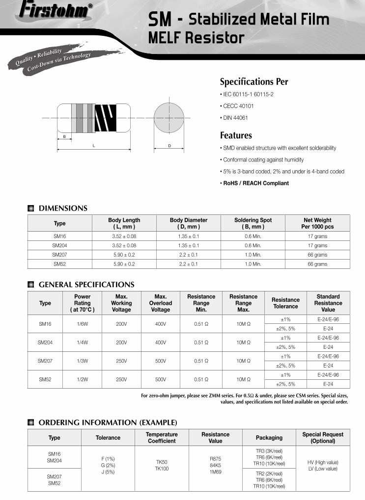
DIMENSIONS
Type Body Length ( L, mm )
Body Diameter ( D, mm )
Soldering Spot ( B, mm )
Net WeightPer 1000 pcs
SM16 3.52 ± 0.08 1.35 ± 0.1 0.6 Min. 17 grams
SM204 3.52 ± 0.08 1.35 ± 0.1 0.6 Min. 17 grams
SM207 5.90 ± 0.2 2.2 ± 0.1 1.0 Min. 66 grams
SM52 5.90 ± 0.2 2.2 ± 0.1 1.0 Min. 66 grams
GENERAL SPECIFICATIONS
TypePowerRating
( at 70°C )
Max.WorkingVoltage
Max.OverloadVoltage
ResistanceRangeMin.
ResistanceRangeMax.
ResistanceTolerance
StandardResistance
Value
SM16 1/6W 200V 400V 0.51 Ω 10M Ω±1% E-24/E-96
±2%, 5% E-24
SM204 1/4W 200V 400V 0.51 Ω 10M Ω±1% E-24/E-96
±2%, 5% E-24
SM207 1/3W 250V 500V 0.51 Ω 10M Ω±1% E-24/E-96
±2%, 5% E-24
SM52 1/2W 250V 500V 0.51 Ω 10M Ω±1% E-24/E-96
±2%, 5% E-24
For zero-ohm jumper, please see ZMM series. For 0.5Ω & under, please see CSM series. Special sizes, values, and specifications not listed available on special order.
ORDERING INFORMATION (EXAMPLE)
Type Tolerance TemperatureCoefficient
ResistanceValue Packaging Special Request
(Optional)
SM16SM204 F (1%)
G (2%)J (5%)
TK50TK100
R87584K51M69
TR3 (3K/reel)TR6 (6K/reel)
TR10 (10K/reel) HV (High value)LV (Low value)
SM207SM52
TR2 (2K/reel)TR6 (6K/reel)
TR10 (10K/reel)
B
L D

GUDECO Elektronik Handelsgesellschaft mbHFirmensitz: Niederlassungen:Siemensstraße 22D-61267 Neu-AnspachTelefon +49 (6081) 4 04-0Fax +49 (6081) 4 04-44
Alte Rhinstraße 16D-12681 BerlinTelefon +49 (30) 29 36 97-79Fax +49 (30) 29 36 97-88
Steinebach 13aA-6850 DornbirnTelefon +43 (5572) 38 65 56-670Fax +43 (5572) 38 65 56-688
Oetterichweg 7D-90411 NürnbergTelefon +49 (911) 53 99 23-0Fax +49 (911) 53 99 23-50
www.gudeco.de • [email protected]
Sep. 30, 2010
Quality • Reliability
Cost-Down via TechnologyQuality • Reliability
Cost-Down via Technology
SM - Stabilized Metal Film MELF Resistor
TECHNICAL SUMMARY
Characteristics Ranges & Limits
Operating Temperature Range, °C -55 ~ +125
Temperature Coefficient, PPM / °C±1%, 2% ±25, ±50
±5% ±100
Dielectric Withstanding Voltage, VAC or DCSM16, SM204 200
SM207, SM52 500
Insulation Resistance, MΩ >104
Film Temperature, °CSM16, SM204, SM207 125
SM52 140
Voltage Coefficient, PPM / V <0.5
Current noise, µV / V
<10KΩ <0.05
10KΩ ~ 100KΩ <0.2
100KΩ ~ 1MΩ <1
1MΩ ~ 10MΩ <3
Power derating 100% for temp. < 70 °C, linearly down to 0% at 125 °C
Failure Rate, pcs/109 device hours <1
Thermal Resistance, K/W <220
Tin Whisker (JESD201 Temperature Cycling & High Temp./Humidity Storage), µm
<5
SURGE PERFORMANCE
0.00001s 0.0001s 0.001s 0.01s 0.1s 1s
PEA
K P
OW
ER
(w
att)
PAPP
LIC
AB
LE
-PR
AT
ED
P
SUR
GE
100
10
1
10us 100us 1ms 10ms 100ms 1s
0.1
SM207, SM52SM16, SM204
0
0.1
0.2
0.3
0.4
0.5
0.6
0.7
0.8
0.9
1
0.0001 0.001 0.01 0.1 1 10
SURGE DURATIONSURGE DURATIONSURGE OFF TIME
SINGLE SURGE PERFORMANCE SURGE POWER DERATING CURVE
Notes:1. SINGLE SURGE PERFORMANCE graph is good for NON REPETITIVE applications operating in an ambient temperature of 70°C or less. For temperatures above 70°C, the graph power must be derated further linearly down to zero at 125°C.
2. To determine applicable surge power in continuous-surge applications: • Identify allowable duration and peak power Psurge of single surge; • Determine ratio of surge duration/surge OFF time in application; • Calculate Papplicable backwardly according to Y-axis of SURGE POWER DERATING CURVE.
GUDECO Elektronik Handelsgesellschaft mbHFirmensitz: Niederlassungen:Siemensstraße 22D-61267 Neu-AnspachTelefon +49 (6081) 4 04-0Fax +49 (6081) 4 04-44
Alte Rhinstraße 16D-12681 BerlinTelefon +49 (30) 29 36 97-79Fax +49 (30) 29 36 97-88
Steinebach 13aA-6850 DornbirnTelefon +43 (5572) 38 65 56-670Fax +43 (5572) 38 65 56-688
Oetterichweg 7D-90411 NürnbergTelefon +49 (911) 53 99 23-0Fax +49 (911) 53 99 23-50
www.gudeco.de • [email protected]
Sep. 30, 2010
Quality • Reliability
Cost-Down via TechnologyQuality • Reliability
Cost-Down via Technology
SM - Stabilized Metal Film MELF Resistor
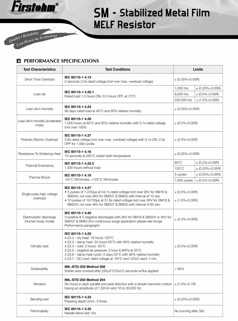
PERFORMANCE SPECIFICATIONS
Test Characteristics Test Conditions Limits
Short Time OverloadIEC 60115-1 4.132 seconds 2.5x rated voltage (not over max. overload voltage)
± (0.05%+0.05R)
Load LifeIEC 60115-1 4.25.1Rated load 1.5 hours ON, 0.5 hours OFF, at 70°C
1,000 hrs ± (0.25%+0.05R)
8,000 hrs ± (0.5%+0.05R)
225,000 hrs ± (1.5%+0.05R)
Load Life In HumidityIEC 60115-1 4.2456 days rated load at 40°C and 93% relative humidity
± (0.25%+0.05R)
Load Life In Humidity (accelerated mode)
IEC 60115-1 4.39 1,000 hours at 85°C and 85% relative humidity with 0.1x rated voltage (not over 100V)
± (0.5%+0.05R)
Periodic Electric OverloadIEC 60115-1 4.373.9x rated voltage (not over max. overload voltage) with 0.1s ON, 2.5s OFF for 1,000 cycles
± (2.5%+0.05R)
Resistance To Soldering HeatIEC 60115-1 4.1810 seconds at 260°C solder bath temperature
± (0.05%+0.05R)
Thermal Endurance IEC 60115-1 4.25.31,000 hours without load
85°C ± (0.2%+0.05R)
125°C ± (0.25%+0.05R)
Thermal Shock IEC 60115-1 4.19-55°C 30minutes, +125°C 30minutes
5 cycles ± (0.05%+0.05R)
1,000 cycles ± (0.5%+0.05R)
Single pulse high voltage overload
IEC 60115-1 4.27• 5 pulses of 1.2/50µs at 44.7x rated voltage (not over 2KV for SM16 & SM204; not over 4KV for SM207 & SM52) with interval of 12 sec. • 10 pulses of 10/700µs at 31.6x rated voltage (not over 2KV for SM16 & SM204; not over 4KV for SM207 & SM52) with interval of 60 sec.
± (0.5%+0.05R)
± (1.0%+0.05R)
Electrostatic discharge (Human body mode)
IEC 60115-1 4.403 positive & 3 negative discharges with 2KV for SM16 & SM204 or 4KV for SM207 & SM52 (For continuous surge application please see Surge Performance paragraph)
± (2.5%+0.05R)
Climatic test
IEC 60115-1 4.234.23.2 - dry heat: 16 hours 125°C4.23.3 - damp heat: 24 hours 55°C with 95% relative humidity4.23.4 - cold: 2 hours -55°C4.23.5 - negative air pressure: 2 hour 8.5KPa at 25°C4.23.6 - damp heat cyclic: 5 days 55°C with 95% relative humidity4.23.7 - DC load: rated voltage at -55°C and 125oC each 1 min.
± (0.5%+0.05R)
SolderabilityMIL-STD-202 Method 208Solder area covered after 230±5°C/5±0.5 seconds w/flux applied
> 95%
VibrationMIL-STD-202 Method 204Six hours in each parallel and axial direction with a simple harmonic motion having an amplitude of 1.52mm and 10 to 20,000 Hz.
± (1.0%+0.1R)
Bending testIEC 60115-1 4.33Pressing depth 2mm, 3 times
± (0.25%+0.05R)
FlammabilityIEC 60115-1 4.35Needle flame test 10s
No burning after 30s

GUDECO Elektronik Handelsgesellschaft mbHFirmensitz: Niederlassungen:Siemensstraße 22D-61267 Neu-AnspachTelefon +49 (6081) 4 04-0Fax +49 (6081) 4 04-44
Alte Rhinstraße 16D-12681 BerlinTelefon +49 (30) 29 36 97-79Fax +49 (30) 29 36 97-88
Steinebach 13aA-6850 DornbirnTelefon +43 (5572) 38 65 56-670Fax +43 (5572) 38 65 56-688
Oetterichweg 7D-90411 NürnbergTelefon +49 (911) 53 99 23-0Fax +49 (911) 53 99 23-50
www.gudeco.de • [email protected]
Sep. 30, 2010
Quality • Reliability
Cost-Down via TechnologyQuality • Reliability
Cost-Down via Technology
SM - Stabilized Metal Film MELF Resistor
Recommended peeling force: 50gf
Type Soldering mode Pad Length(L, mm, min.)
Pad Spacing(P, mm)
Pad Width(W, mm, min.)
SM16SM204
Reflow 1.0 2.0 ± 0.2 1.6
Wave 1.2 2.0 ± 0.2 1.6
SM207SM52
Reflow 2.0 3.0 ± 0.3 3.0
Wave 2.5 3.0 ± 0.3 3.0
For better heat dissipation / lower heat resistance, increase W & L.
SUGGESTED PAD LAYOUT
COVER TAPE PEELING SPECIFICATION

SM- Stabilized Metal Film MELF Resistor Specifications Per Features IEC 60115-1 60115-2 SMD enabled structure CECC 40101 Conformal coating against humidity DIN 44061 Excellent solderability termination
5% is 3-band coded, 2% and under is 4-band coded
Dimensions
Type Body Length (L, mm)
Body Diameter (D, mm)
Soldering spot (B, mm)
Net Weight Per 1000 pcs
SM16 3.45 ± 0.1 1.35 ± 0.1 0.6 Min. 17 grams
SM204 3.45 ± 0.1 1.35 ± 0.1 0.6 Min. 17 grams
SM207 5.9 ± 0.2 2.2 ± 0.1 1.0 Min. 66 grams
SM52 5.9 ± 0.2 2.2 ± 0.1 1.0 Min. 66 grams
General Specifications
Type Power Rating
(at 70oC)
Max. Working Voltage
Max. Overload Voltage
Resistance Range Min.
Resistance Range Max.
Resistance Tolerance
Standard Resistance
Value ±1% E-24/E-96
SM16 1/6W 200V 400V 0.1 1M ±2%, 5% E-24
±1% E-24/E-96 SM204 1/4W 200V 400V 0.1 1M
±2%, 5% E-24
±1% E-24/E-96 SM207 1/3W 250V 500V 0.1 1M
±2%, 5% E-24
±1% E-24/E-96 SM52 1/2W 250V 500V 0.1 1M
±2%, 5% E-24 For zero ohm jumper, please see ZMM series. For 1m~100mohm, please see CSM series. Special sizes, values, and specifications not listed available on special order.
Aug. 28, 2004

SM- Stabilized Metal Film MELF Resistor
1 .2 /5 0 u s P E A K P U L S E5 p u ls e s a t 1 2 -s e c in te rv a l fo r 0 .5 % p e rm a n e n t c h a n g e
1 0
1 0 0
1 0 0 0
1 0 0 0 0
R E S IS T A N C E V A L U E
PEA
K V
OLT
AG
E (v
olt)
1 Ω 1 0 Ω 1 0 0 Ω 1 K Ω 1 0 K Ω 1 0 0 K Ω 1 M Ω
S M 2 0 7 , S M 5 2
S M 1 6 , S M 2 0 4
POWER DERATING CURVE
0%
10%
20%
30%
40%
50%
60%
70%
80%
90%
100%
30 40 50 60 70 80 90 100 110 120 130
AMBIENT TEMPERATURE (oC)
RATEDLOAD
SURGE POW ER DERATING CURVE
0
0.1
0.2
0.3
0.4
0.5
0.6
0.7
0.8
0.9
1
0.0001 0.001 0.01 0.1 1 10
Surge Duration Surge OFF time
Pap
plic
able
- P
rate
dP
surg
e
SINGLE SURGE PERFORMANCE
0.00001s 0.0001s 0.001s 0.01s 0.1s 1s
SURGE DURATION
PEA
K P
OW
ER (w
att)
100
10
1
10us 100us 1ms 10ms 100ms 1s
0.1
SM207, SM52
SM16, SM204
Notes: 1. Above graph is accurate for NON REPETITIVE applications operating in an ambient temperature of 70°C or less. For temperatures above 70°C, the graph power must be derated further linearly down to zero at 125°C. 2. For applicable surge power in continuous-surge applications please see SURGE POWER DERATING CURVE above.
Aug. 28, 2004

Aug. 28, 2004
SM- Stabilized Metal Film MELF Resistor Technical Summary:
Characteristics Limits
Dielectric Withstanding Voltage, VAC or DC SM16, SM204: 200 SM207, SM52: 500 ±1%, 2% ±50 Temperature Coefficient, PPM / ±5% ±100
Operating Temperature Range, -55 ~ +125 SM16 SM204 SM207 SM52 Film Temperature, 125 125 125 140
Insulation Resistance, MΩ >104
Performance Specifications Test Characteristics Test Conditions Limits
Short Time Overload IEC 60115-1 4.13 5 seconds 2.5x rated voltage (not over max. overload voltage) ±(0.5%+0.05R)
Load Life In Humidity IEC 60115-1 4.24 56 days at 40oC and 93% relative humidity ±(1.5%+0.05R)
Load Life 1,000 hours ±(0.25%+0.05R) Load Life 8,000 hours ±(0.5%+0.05R) Load Life 225,000 hours
IEC 60115-1 4.25.1 Rated load 1.5 hours ON, 0.5 hours OFF, at 70oC
±(1.5%+0.05R) Resistance To Soldering Heat
IEC 60115-1 4.18 10 seconds at 260oC solder bath temperature ±(0.5%+0.05R)
Solderability MIL-STD-202 Method 208 Solder area covered after 230+5oC/5+0.5 seconds w/ flux applied 95% Min.
Vibration IEC 60115-1 4.22 Six hours in each parallel and axial direction w/ a simple harmonic motion having an amplitude of 0.75mm and 10 to 500 Hz.
±(1%+0.1R)
Thermal Endurance IEC 60115-1 4.25.3 1000 hours at 125oC without load ±(0.5%+0.05R)
Thermal Shock IEC 60115-1 4.19 -55oC 30minutes, +125oC 30minutes, 5 cycles ±(0.5%+0.05R)
Ordering Information
Type Tolerance Temperature Coefficient
Resistance Value Packaging
Special Request
(Optional)
SM204 F (1%) G (2%) J (5%)
TK50 TK100
562R 84K5 1M69
B (Bulk) TR (Tape/Reel)
HV (High value)