slr-434sc operation guide|circuit design, inc. · a mode with fsk modulation for sending and...
TRANSCRIPT

OG_SLR-434SC_v11e Circuit Design, Inc.1
Embedded low power radio modem
SLR-434MSmart RF modem
Serial communication
Operation GuideVersion 1.1 (Sep. 2018)
Circuit Design, Inc.
7557-1 Hotaka, Azumino, Nagano, JapanTel: 0263-82-1024
Fax: 0263-82-1016
e-mail: [email protected]://www.circuitdesign.jp

OG_SLR-434SC_v11e Circuit Design, Inc.2
Contents
1. Summary ............................................................................................................................................. 4
2. Control commands and control responses..................................................................................... 4
2.1 Basic format of control commands and control responses............................................................ 4
2.2 “@CH” Set frequency channel ....................................................................................................... 5
2.3 “@MO” Set radio communication mode ........................................................................................ 5
2.4 “@SF” Set the number of chips (spreading factor) with LoRa modulation .................................... 6
2.5 “@EI” Set Equipment ID................................................................................................................. 6
2.6 “@DI” Set Target station ID ............................................................................................................ 7
2.7 “@GI” Set Group ID ....................................................................................................................... 7
2.8 “@UI” Set User ID.......................................................................................................................... 7
2.9 “@RS” Acquire RSSI for the last data received ............................................................................. 8
2.10 “@RA” Acquire the current RSSI value........................................................................................ 8
2.11 “@CI” RSSI output on/off during carrier sensing (LoRa command mode only)........................... 8
2.12 “@FV”, “@VR” Acquire firmware version................................................................................... 9
2.13 “@SN” Acquire Serial Number ..................................................................................................... 9
2.14 Building a communication system between radio stations .......................................................... 9
3. Error responses to control commands...........................................................................................11
3.1 Basic format of error responses....................................................................................................11
3.2 Error code for “@CH” frequency channel setting command.........................................................11
3.3 Error code for “@MO” communication mode setting command ...................................................11
3.4 Error code for “@SF” number of chips setting command .............................................................11
3.5 Error code for “@EI” Equipment ID setting command ..................................................................11
3.6 Error code for “@DI” Target station ID setting command..............................................................11
3.7 Error code for “@GI” Group ID setting command........................................................................ 12
3.8 Error code for “@UI” User ID setting command........................................................................... 12
3.9 Error code for “@RA” Current RSSI acquisition command ......................................................... 12
3.10 Error code for the “@CI” RSSI output on/off during carrier sensing.......................................... 12
3.11 Other........................................................................................................................................... 12
4. Wireless data transmission commands and data transmission responses .............................. 13
4.1 Basic format of data transmission commands and responses .................................................... 13
5. Error responses to data transmission commands ....................................................................... 14
5.1 Basic format of error responses................................................................................................... 14

OG_SLR-434SC_v11e Circuit Design, Inc.3
6. Information responses (LoRa command mode only) ................................................................... 14
6.1 Basic format of information responses......................................................................................... 14
6.2 Response to carrier sensing (only with LoRa command mode) .................................................. 14
6.3 Response to correlation sensing (only with LoRa command mode) ........................................... 15
6.4 Data transmission complete response (only with LoRa command mode) .................................. 15
7. Receive data from the target station .............................................................................................. 16
7.1 Basic format of received data....................................................................................................... 16
8. Contact function ............................................................................................................................... 17
8.1 Basic format of control commands and control responses.......................................................... 17
8.2 “@PI” Set Unique ID for contact communication ......................................................................... 188.2.1 Check Unique ID currently set.............................................................................................. 188.2.2 Set to 'Not using Unique ID' (factory setting)........................................................................ 188.2.3 Set Unique ID to the local station ......................................................................................... 188.2.4 Receive Unique ID and set it as its own Unique ID.............................................................. 198.2.5 Transmit Unique ID .............................................................................................................. 198.2.6 Unique ID setting examples.................................................................................................. 19
8.3 “@PS” Set input/output port......................................................................................................... 20
8.4 “@PO” Set and acquire the local station port status.................................................................... 218.4.1 Set the status of the local station port................................................................................... 218.4.2 Acquire the status of the local station port............................................................................ 22
8.5 “@PT” Set and acquire the target station port status .................................................................. 238.5.1 Acquire the status of the target station port .......................................................................... 238.5.2 Set the status of the target station port................................................................................. 23
8.6 “@PM” Set contact function communication mode...................................................................... 248.6.1 Specified times transmission mode when changing input ports (LoRa/FSK command mode)....................................................................................................................................................... 248.6.2 One-way continuous transmission mode (FSK command mode only) ................................ 258.6.3 Two-way continuous communication mode (FSK command mode only)............................. 25
8.7 “@PF” Set output port holding time ............................................................................................. 25
8.8 Contact function responses ......................................................................................................... 268.8.1 "PR" response....................................................................................................................... 268.8.2 'PD' response........................................................................................................................ 288.8.3 Combination of the 'PR' and 'PD' responses........................................................................ 28
9. Command list.................................................................................................................................... 29
10. Channel plan ................................................................................................................................... 32
11. Data transmission time in the FSK/LoRa mode .......................................................................... 34
11.1 Data transmission time in the FSK mode................................................................................... 34
11.2 Data transmission time in the LoRa mode ................................................................................ 34
11.3 Data transmission time............................................................................................................... 36
OG_SLR-434SC_v11e Circuit Design, Inc.4
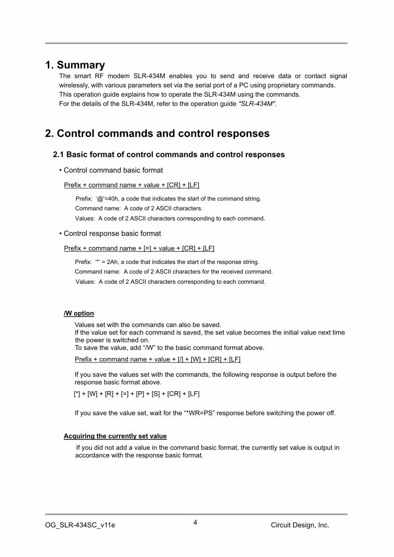
1. SummaryThe smart RF modem SLR-434M enables you to send and receive data or contact signal
wirelessly, with various parameters set via the serial port of a PC using proprietary commands.
This operation guide explains how to operate the SLR-434M using the commands.
For the details of the SLR-434M, refer to the operation guide "SLR-434M".
2. Control commands and control responses
2.1 Basic format of control commands and control responses
• Control command basic format
Prefix + command name + value + [CR] + [LF]
Prefix: ‘@’=40h, a code that indicates the start of the command string.
Command name: A code of 2 ASCII characters.
Values: A code of 2 ASCII characters corresponding to each command.
• Control response basic format
Prefix + command name + [=] + value + [CR] + [LF]
Prefix: ‘*’ = 2Ah, a code that indicates the start of the response string.
Command name: A code of 2 ASCII characters for the received command.
Values: A code of 2 ASCII characters corresponding to each command.
/W option
Values set with the commands can also be saved.If the value set for each command is saved, the set value becomes the initial value next timethe power is switched on.To save the value, add “/W” to the basic command format above.
Prefix + command name + value + [/] + [W] + [CR] + [LF]
If you save the values set with the commands, the following response is output before theresponse basic format above.
[*] + [W] + [R] + [=] + [P] + [S] + [CR] + [LF]
If you save the value set, wait for the “*WR=PS” response before switching the power off.
Acquiring the currently set value
If you did not add a value in the command basic format, the currently set value is output inaccordance with the response basic format.

OG_SLR-434SC_v11e Circuit Design, Inc.5
2.2 “@CH” Set frequency channel
Sets the frequency channel to be used.
The default setting at shipment is ‘4’'A’ (434.000 MHz).
Input the 2-character ASCII code after ‘@CH’ to set the channel.
Values: ‘0’ ‘0' - ‘8’ ‘8’ (A hexadecimal ASCII code showing channels from 0 to 136)
Example: Change to 0Eh (change to channel 14)
Control command: @CH0E
Control response: *CH=0E
* Refer to the channel table in “10. Channel plan”.
2.3 “@MO” Set radio communication mode
Sets the wireless communication mode.
There are the following 5 types of wireless communication mode.
The default setting at shipment is ‘0’ ‘3’ (LoRa command mode).
Input the 2-character ASCII code after ‘@MO’ to set the communication mode.
Values: ‘0’ ‘0’: FSK binary mode
‘0’ ‘1’: FSK command mode
‘0’ ‘2’: LoRa binary mode
‘0’ ‘3’: LoRa command mode
‘0’ ‘4’: Air monitor mode
Example: Change to 01h (Change to the FSK command mode)
Control command: @MO01
Control response: *WR=PS
*MO=01
*If a wireless communication mode is set, the setting is automatically saved and the device
restarts. (Even if the "/W" option is not used, the response "*WR=PS" is returned. )
Mode Content Value
FSK binary mode A mode with FSK modulation for use as a transparent modem. 00
FSK command modeA mode with FSK modulation for sending and receiving data usingproprietary commands.
01
LoRa binary mode A mode with LoRa modulation for use as a transparent modem. 02
LoRa command modeA mode with LoRa modulation for sending and receiving datausing proprietary commands.
03
Air monitor modeA mode for measuring the RSSI level of each channel.*a separate application is needed.
04

OG_SLR-434SC_v11e Circuit Design, Inc.6
After restarting, the following string is output to the serial port.
“FSK BIN MODE”: When set to the FSK binary mode
“FSK CMD MODE”: When set to the FSK command mode
“LORA BIN MODE”: When set to the LoRa binary mode
“LORA CMD MODE”: When set to the LoRa command mode
“AIR MONITOR MODE”: When set to the air monitor mode
*When set to the FSK binary mode or the LoRa binary mode, commands are not accepted asthe SLR-434M works as a transparent modem.If you want to change the mode, set the INI terminal of the SLR-434M to Low for at least 3seconds (See "SLR-434M" operation guide).
* When you changed the communication mode, wait for the string such as "LORA CMDMODE" that is output after restarting before you turn off the power.
2.4 “@SF” Set the number of chips (spreading factor) with LoRamodulation
Sets the number of chips for LoRa modulation.
The default setting at shipment is ‘0’ ‘0’ (128 chips).
Input the 2-character ASCII code after ‘@SF’ to set the number of chips.
Values: ‘0’ ‘0’: 128 chips (Spreading factor: 7, Measured value: 245 bps)
‘0’ ‘1’: 256 chips (Spreading factor: 8, Measured value: 146 bps)
‘0’ ‘2’: 512 chips (Spreading factor: 9, Measured value: 86 bps)
‘0’ ‘3’: 1024 chips (Spreading factor: 10, Measured value: 49 bps)
‘0’ ‘4’: 2048 chips (Spreading factor: 11, Measured value: 27 bps)
‘0’ ‘5’: 4096 chips (Spreading factor: 12, Measured value: 15 bps)
Example: Set to 00h (LoRa 128 chips)
Control command: @SF00
Control response: *SF=00
*As the number of chips increases, the impact of the Doppler effect becomes greater when
moving around, and communication becomes less reliable.
2.5 “@EI” Set Equipment ID
Sets the individual ID for each device.
The default setting at shipment is ‘0’ ‘1’.
Input the 2-character ASCII code after ‘@EI’ to set the ID.
Values: ‘0’ ‘0' - ‘F’ ‘F’ (A hexadecimal ASCII code showing values from 0 to 255)
Example: Change to 0Ah (Set the Equipment ID to 10)
Control command: @EI0A
Control response: *EI=0A

OG_SLR-434SC_v11e Circuit Design, Inc.7
2.6 “@DI” Set Target station ID
Specifies the target station to communicate with.
The default setting at shipment is ‘0’ ‘1’.
Input the Equipment ID of the target station after ‘@DI’ with the 2-character ASCII code.
Values: ‘0’ ‘0' - ‘F’ ‘F’ (A hexadecimal ASCII code showing values from 0 to 255)
Example: Change to 0Ah (Set the Target station ID to 10)
Control command: @DI0A
Control response: *DI=0A
*If the Target station ID is set to ‘0’ ‘0’ and transmitted, communication changes to multi-addresscalling within the Group.
*When performing communication with one base unit and several slave units (1:Ncommunication), the base unit can communicate with a specific slave unit by specifying theEquipment ID set for the slave unit as the target station with the @DI command..
See “2.14 Building a communication system between radio stations” for details.
2.7 “@GI” Set Group ID
The Group ID is the ID that identifies a group in the user system. Set the same Group ID for all
the radio stations within the group. Maintain Group IDs as identification numbers when building
other systems.
The default setting at shipment is ‘0’ ‘0’.
Input the 2-character ASCII code after ‘@GI’ to set the ID.
Values: ‘0’ ‘0' - ‘F’ ‘F’ (A hexadecimal ASCII code showing values from 0 to 255)
Example: Change to 0Ah (set the Group ID to 10)
Control command: @GI0A
Control response: *GI=0A
2.8 “@UI” Set User ID
User identification ID assigned to a user. Communication is not possible unless all equipment
within the user system is set with the same User ID. When a single user builds multiple systems,
they are identified with a Group ID.
The setting command is ‘@UI + User ID + ‘,’ + password.
The default setting at shipment is ‘0’ ‘0’ ‘0’ ‘0’.
It can be used without User IDs, however, we recommend that you set a User ID to prevent
radio interference within a given area. If you require User IDs, please contact Circuit Design, Inc.
Input the 4-character ASCII code after ‘@UI’ to set the ID, and after ‘,’ enter a 4-character ASCII
code password.
Example: Control command: @UI0000,XXXX (XXXX is the password part)
Control response: *WR=PS
*UI=0000 (To set back to 0000, input 2367 for password.)
* When the UI command is issued, the setting is automatically saved and the device restarts.
(Even if the "/W" option is not used, a *WR response is returned. )

OG_SLR-434SC_v11e Circuit Design, Inc.8
2.9 “@RS” Acquire RSSI for the last data received
If this command is implemented immediately after receiving data, you can acquire the Received
Signal Strength Indicator (RSSI) value when the data was received. The output format for the
RSSI value is as follows.
*RS=###dBm (The ### part is the RSSI value when the data was received)
Example: Control command: @RS
Control response: *RS=-82dBm
2.10 “@RA” Acquire the current RSSI value
Acquires the current Received Signal Strength Indicator (RSSI) value of the channel set.
*RA=###dBm (The ### part is the RSSI value when the data was received)
Example: Control command: @RA
Control response: *RA=-122dBm
2.11 “@CI” RSSI output on/off during carrier sensing (LoRa command modeonly)
Sets whether to output the RSSI value automatically to the UART during carrier sensing.
When set to "Output", the RSSI value is output following the usual response when wireless
transmission is performed with the command such as @DT. For more details, see "6.2
Response to carrier sensing".
The default setting at shipment is ‘0’ ‘0’ (No output).
Input the 2-character ASCII code after ‘@CR’ to set the status.
Values: ‘0’ ‘0’: No output to the UART
‘0’ ‘1’: Output to the UART
Example: Change to 01 (Output to the UART)
Control command: @CI01
Control response: *CI=01
Important note:
If the SLR-434M receives interference signal of more than -40 dBm from other radio devices, even if
the receiving frequencies are different, correct RSSI values may not be acquired and also carrier
sensing may determine that transmission is not possible.
When setting up the radio devices, try to keep the distance between them as long as possible.
The RSSI value acquired with the @CI command may be different from the value acquired with the
@RA command. This is because the RSSI acquisition with the @CI uses a process to alleviate the
influence of interference.

OG_SLR-434SC_v11e Circuit Design, Inc.9
2.12 “@FV”, “@VR” Acquire firmware version
You can acquire the firmware version.
Example 1: Control command: @FV
Control response: *FV = #.###,SLR-434M (The version goes in the #.### part.)
Example 2: Control command: @VR
Control response: *VR = SLR-434M_V#R###, (The version goes in the # ###
part.)
2.13 “@SN” Acquire Serial Number
You can acquire the Serial Number.
Example: Control command: @SN
Control response: *SN = $####### (The $####### part is the serial number
consisting of 1-digit alphabet and 7-digit numbers.)
2.14 Building a communication system between radio stations
The SLR-434M can be used for building 1:1, 1:N, and M:N systems.
Equipment IDs from 01h to FFh can be specified, and a maximum of 255 units can be
connected in 1 group.
With 1:1 (1:N) communication, specify the Target station ID with the @DI command and send
data with the @DT command.
1:1 system for communication within a group
By setting the same Group ID and setting the Target station ID and Equipment ID as a pair,
you can create a 1:1 system.
*Set the Target station ID to something other than 00h.
Setting example:
Each ID Device 1 Device 2
Group ID 02h 02h
Target station ID 03h 05h
Equipment ID 05h 03h
1:N and M:N systems for communication within a group
If the Group IDs are set the same and the Target station ID specified for the local station
and the Equipment ID of the target station match, data is output to the target station.
In a 1:N system, it is also possible to build an M:N system in which all the units have an
equal relationship.
Setting example: Settings for communication between a master unit and 3 slave units.
Each ID Master Slave 1 Slave 2 Slave 3
Group ID 02h 02h 02h 02h
Target station ID 02h, 03h, 04h* 01h 01h 01h
Equipment ID 01h 02h 03h 04h
*In this example, the master unit specifies one of the three slave units for each transmission.
Before sending data with the data transmission command, specify the Equipment ID set for
each slave unit with the Target station ID setting command.

OG_SLR-434SC_v11e Circuit Design, Inc.10
Multi-address calling within a group
If the Target station ID is specified as 00h at the master station and data is transmitted, all
target stations in the group will receive the data at the same time, irrespective of the
Equipment ID.
Communication between groups
When several groups are created with the same Target station ID and Equipment ID set as
pairs, it is possible to communicate with another group by changing the Group ID when
transmitting.
Setting example 1:
Group 1
Each ID Device 1 Device 2
Group ID 02h 02h
Target station ID 05h 03h
Equipment ID 03h 05h
Group 2
Each ID Device 1 Device 2
Group ID 03h 03h
Target station ID 05h 03h
Equipment ID 03h 05h
Setting example 2:
Group 1
Each ID Master Slave 1 Slave 2 Slave 3
Group ID 02h 02h 02h 02h
Target station ID 02h, 03h, 04h* 01h 01h 01h
Equipment ID 01h 02h 03h 04h
Group 2
Each ID Master Slave 1 Slave 2 Slave 3
Group ID 03h 03h 03h 03h
Target station ID 02h, 03h, 04h* 01h 01h 01h
Equipment ID 01h 02h 03h 04h
*In this example, the master unit specifies one of the three slave units for each transmission.
Before sending data with the data transmission command, specify the Equipment ID set for
each slave unit with the Target station ID setting command.

OG_SLR-434SC_v11e Circuit Design, Inc.11
3. Error responses to control commands
3.1 Basic format of error responses
Prefix + error string + [=] + error code + [CR] + [LF]
Prefix: ‘*’ = 2Ah, a code that indicates the start of the error response string.Error string: ‘E’ ’R’, a code of 2 ASCII characters.Error code: A code of 2 ASCII characters representing an error code corresponding to each command.
Example: [*] + [E] + [R] + [=] + [0] + [4] + [CR] + [LF]
3.2 Error code for “@CH” frequency channel setting command
There are the following 3 types of error code.
Error code Content
“02” Output if an undefined channel is specified.
“03” Output if the format of the frequency channel setting command is wrong.
“01” Output when the error code is not “02” or “03”.
3.3 Error code for “@MO” communication mode setting command
There are the following 3 types of error code.
Error code Content
“02” Output if an undefined communication mode is specified.
“03”Output if the format of the communication mode setting command iswrong.
“01” Output when the error code is not “02” or “03”.
3.4 Error code for “@SF” number of chips setting command
There are the following 3 types of error code.
Error code Content
“02” Output if an undefined number of chips is specified.
“03” Output if the format of the number of chips setting command is wrong.
“01” Output when the error code is not “02” or “03”.
3.5 Error code for “@EI” Equipment ID setting command
There are the following 2 types of error code.
Error code Content
“03” Output if the format of the Equipment ID setting command is wrong.
“01” Output when the error code is not “03”.
3.6 Error code for “@DI” Target station ID setting command
There are the following 2 types of error code.
Error code Content
“03” Output if the format of the Target station ID setting command is wrong.
“01” Output when the error code is not “03”.

OG_SLR-434SC_v11e Circuit Design, Inc.12
3.7 Error code for “@GI” Group ID setting command
There are the following 2 types of error code.
Error code Content
“03” Output if the format of the Group ID setting command is wrong.
“01” Output when the error code is not “03”.
3.8 Error code for “@UI” User ID setting command
There are the following 2 types of error code.
Error code Content
“03” Output if the format of the User ID setting command is wrong.
“04” Output if the password does not match.
3.9 Error code for “@RA” Current RSSI acquisition command
There is the following error code.
Error code Content
“05” Output if the SLR-434M is not in receiving state.
3.10 Error code for the “@CI” RSSI output on/off during carrier sensing
There are the following 3 types of error code.
Error code Content
“02” Output if an undefined setting value is specified.
“03” Output if the format of the setting command is wrong.
“01” Output when the error code is not “02” or “03”.
3.11 OtherIf there is an undefined control command, the error code “01” is output.

OG_SLR-434SC_v11e Circuit Design, Inc.13
4. Wireless data transmission commands and datatransmission responses
Using data transmission commands, you can send any data you want wirelessly.
If the transmission data is set correctly, a data transmission response is returned.
4.1 Basic format of data transmission commands and responses
Basic format of data transmission commands
Prefix + command name + transmission data byte count + transmission data + [CR] + [LF]
Prefix: ‘@’=40h, a code that indicates the start of the command string.
Command name: ‘D’ ’T’, a code of 2 ASCII characters.
Transmission data byte count: Specify the byte count of user data in hex (‘0’ ‘0' to ‘F’ ‘F’).
Transmission data: Byte strings of user data. You can set all binary data from 00h to FFh Hex.
Example: Sending the character string “ABCDEF”
[@] + [D] + [T] + [0] + [6] + [A] + [B] + [C] + [D] + [E] + [F] + [CR] + [LF]
Example: Sending the binary data 00h, 01h, 02h, 03h, 04h
[@] + [D] + [T] + [0] + [5] + [00h] + [01h] + [02h] + [03h] + [04h] + [CR] + [LF]
Example: Sending 255-byte data
[@] + [D] + [T] + [F] + [F] + ・・・・・・・・・・・・・・・・・・・・・・ ・・ + [CR] + [LF]
Basic format of responses to data transmission commands
Prefix + response name + [=] + transmission data byte count + [CR] + [LF]
Prefix: ‘*’ = 2Ah, a code that indicates the start of the response string.
Response name: ‘D’ ’T’, a code of 2 ASCII characters.
Data byte count: The same value as the data byte count set with transmit data command is set.
Example: Data transmission command
[@] + [D] + [T] + [0] + [6] + [A] + [B] + [C] + [D] + [E] + [F] + [CR] + [LF]
Data transmission response
[*] + [D] + [T] + [=] + [0] + [6] + [CR] + [LF]
Note:In wireless communication, the longer data length you use, the higher communication errorprobability there will be. Try to minimize the data length.It is recommended to use a data length of 45 bytes or less in the FSK command mode.(In the FSK command mode, if the size of transmission data exceeds 45 bytes, the data is sentin several packets.)

OG_SLR-434SC_v11e Circuit Design, Inc.14
5. Error responses to data transmission commands
5.1 Basic format of error responses
Prefix + error string + [=] + error code + [CR] + [LF]
Prefix: ‘*’ = 2Ah, a code that indicates the start of the error response string.Error string: ‘E’ ’R’, a code of 2 ASCII characters.Error code: A code of 2 ASCII characters representing an error code corresponding to each command.
Example: [*] + [E] + [R] + [=] + [0] + [3] + [CR] + [LF]
The details of the error codes are shown in the table below.Error code Content
“03” Output if the format of the data transmission command is wrong.
“01” Output when the error code is not “03”.
6. Information responses (LoRa command mode only)
When the LoRa command mode is set, an information response is output if the device cannot emitradio waves due to carrier sensing or correlation sensing and when data transmission completes.In other communication modes such as FSK command mode, FSK binary mode, LoRa binarymode, the information response is not output.
6.1 Basic format of information responses
Prefix + information string + [=] + response code + [CR] + [LF]
Prefix: ‘*’ = 2Ah, a code that indicates the start of the information response string.Information string: ‘I’ ’R’, a code of 2 ASCII characters.Response code: A code of 2 ASCII characters representing each response.
Example: [*] + [I] + [R] + [=] + [0] + [3] + [CR] + [LF]
6.2 Response to carrier sensing (only with LoRa command mode)The SLR-434M performs carrier sensing automatically internally.
When transmitting data, if the channel selected is being used by other equipment, the device
does not emit radio waves.
When carrier sensing determines that transmission is not possible, the character string “*IR=01”
is output after the data transmission response.
If data cannot be transmitted, it is not retransmitted.
Example: Data transmission command
[@] + [D] + [T] + [0] + [6] + [A] + [B] + [C] + [D] + [E] + [F] + [CR] + [LF]
Data transmission response
[*] + [D] + [T] + [=] + [0] + [6] + [CR] + [LF]
When data could not be transmitted
[*] + [I] + [R] + [=] + [0] + [1] + [CR] + [LF]

OG_SLR-434SC_v11e Circuit Design, Inc.15
If RSSI output during carrier sensing is enabled with '@CI01', the RSSI value is output followingthe above response.(The RSSI value is also output when transmission is performed with the '@PT' command or'@PMxx' command. )
Example) When the RSSI value is -110 dBm[R] + [S] + [S] + [I] + [=] + [-] + [1] + [1] + [0] + [d] + [B] + [m] + [CR] + [LF]
6.3 Response to correlation sensing (only with LoRa command mode)
With LoRa modulation, communication is possible at levels lower than city noise, so it is not
possible to check for the presence of other LoRa modulation radio waves before emitting with
the carrier sensing in 6.2 alone.
Therefore, the SLR-434M uses a proprietary method called correlation sensing to check for the
presence of other LoRa modulation radio waves before emitting waves.
When correlation sensing determines that transmission is not possible due to the presence of
other LoRa modulation radio waves, the character string “*IR=02” is output after the data
transmission response.
If data cannot be transmitted, it is not retransmitted.
Example: Data transmission command
[@] + [D] + [T] + [0] + [6] + [A] + [B] + [C] + [D] + [E] + [F] + [CR] + [LF]
Data transmission response
[*] + [D] + [T] + [=] + [0] + [6] + [CR] + [LF]
When data could not be transmitted
[*] + [I] + [R] + [=] + [0] + [2] + [CR] + [LF]
6.4 Data transmission complete response (only with LoRa command mode)
When the LoRa command mode is set, the following response is output after all the data set
with @DT is sent.(This response is also output when contact signal is transmitted with the PT command.)
[*] + [I] + [R] + [=] + [0] + [3] + [CR] + [LF]
*To send data continuously, set the transmission data as follows.
FSK command mode: Wait for the data transmission responseLoRa command mode: Wait for the data transmission complete response

OG_SLR-434SC_v11e Circuit Design, Inc.16
7. Receive data from the target stationIf the SLR-434M receives data from the target station, it outputs the received data with the
following format.
7.1 Basic format of received data
Prefix + response name + [=] + received data byte count + received data + [CR] + [LF]
Prefix: ‘*’ = 2Ah, a code that indicates the start of the response string.
Response name: ‘D’ ’R’, a code of 2 ASCII characters.
Received data byte count: ‘0’ ‘0' to ‘F’ ‘F’ (A hexadecimal ASCII code showing values from 0 to 255)
Received data: Received data
Example: Data transmission command on the transmitter side
[@] + [D] + [T] + [0] + [6] + [A] + [B] + [C] + [D] + [E] + [F] + [CR] + [LF]
Received data on the receiver side
[*] + [D] + [R] + [=] + [0] + [6] + [A] + [B] + [C] + [D] + [E] + [F] + [CR] + [LF]

OG_SLR-434SC_v11e Circuit Design, Inc.17
8. Contact functionThe SLR-434M enables you to transmit and receive contact data wirelessly using the DIO
terminals and proprietary commands
This chapter explains the contact function and the commands used for contact data
communication. For the DIO terminals, refer to the operation guide "SLR-434M".
For safety operation of the contact function, it is recommended to set a user ID ('@UI') and a
Unique ID ('@PI').
(The PI command was added to the FW version 1.081 and later.)
8.1 Basic format of control commands and control responses
• Control command basic format
Prefix + command name + value + [CR] + [LF]
Prefix: ‘@’=40h, a code that indicates the start of the command string.
Command name: A code of 2 ASCII characters.
Value: A code of 2 ASCII characters corresponding to each command.
• Control response basic format
Prefix + command name + [=] + value + [CR] + [LF]
Prefix: ‘*’ = 2Ah, a code that indicates the start of the response string.
Command name: A code of 2 ASCII characters for the received command.
Value: A code of 2 ASCII characters corresponding to each command.
/W option
Values set with the following commands can also be saved.
@PS command@PO command@PM command@PF command
If the value set for each command is saved, the set value becomes the initial value next timethe power is switched on.To save the value, add “/W” to the basic command format above.
Prefix + command name + value + [/] + [W] + [CR] + [LF]
If you save the values set with the commands, the following response is output before theresponse basic format above.
[*] + [W] + [R] + [=] + [P] + [S] + [CR] + [LF]
If you save the value set, wait for the response “*WR=PS” before switching the power off.
Acquiring the currently set values
If you did not add a value in the command basic format, the currently set value is output inaccordance with the response basic format.

OG_SLR-434SC_v11e Circuit Design, Inc.18
8.2 “@PI” Set Unique ID for contact communication
Setting the Unique ID for contact communication ensures safety operation of the contactfunction.All radio stations in a system need to be set with the same Unique ID.Since the serial number individually allocated to the SLR-434M unit is read out and used as theUnique ID, the user cannot use the Unique IDs allocated to the units other than the units theyown. This prevents malfunctions due to interference with other users.
Identification by setting '@ EI', '@ DI', '@ GI', '@ UI', that is explained in the previous sections, isalso available in contact data communication. However, since the IDs other than User ID can beset to any value, there is a possibility that radio stations set with the same ID accidentallycommunicate each other.Identification by the Unique ID can be freely set and used by the user.
The serial number of the SLR-434M consists of 1 alphabetical letter and 7-digit numbers. Theserial number described below means the 7-digit numbers.
8.2.1 Check Unique ID currently set
Control command: @PIExample 1) Control response: * PI=000000 (000000 means the Unique ID is set to 'Not using'.)Example 2) Control response: * PI=12D687 (When the Unique ID is set, the ID is returned.
12D687 (Hex) = 1234567)
* When the Unique ID is used, 3-byte data is added to the data format, resulting in a longertransmission time.
8.2.2 Set to 'Not using Unique ID' (factory setting)
Control command: @PICControl response: *WR=PS (This response means the setting is saved.)
*PI=000000 (Cleared to 000000)
8.2.3 Set Unique ID to the local station
Set the Unique ID to the local station with its own serial number.
Example) When the SLR-434M of the local station has "S/No. A1234567" on its label.
Control command: @PISControl response: *WR=PS (This response means the setting is saved.)
*PI=12D687 (12D687 (Hex) = 1234567)

OG_SLR-434SC_v11e Circuit Design, Inc.19
8.2.4 Receive Unique ID and set it as its own Unique ID
Sets the local station into a ready state to receive the Unique ID sent from other equipment. .
Control command: @PIRControl response: *PI=Ready (Ready to receive the Unique ID)
(Receive response example)
*PR=100212D687
*WR=PS (This response means the setting is saved.)*PI=12D687 (Unique ID set to the local station)
*The ready state is cancelled when the function code for Unique ID setting is received and alsowhen other '@PI' commands ('@PI', '@PIC', '@PIS', '@PIT') are executed. .
8.2.5 Transmit Unique ID
Transmit the Unique ID of the local station to the target station that is in a ready state to receivethe Unique ID.
Control command: @PITControl response: *PI=12D687 (The transmitted ID is returned)
* Set the target station to the Unique ID waiting mode (ready state) before executing thiscommand.It is possible to set a Unique ID to multiple target stations simultaneously.
* If this command is executed when 'Not using Unique ID' is set (PI=000000), the target stationsare also set to 'Not using Unique ID'.
8.2.6 Unique ID setting examples
When performing contact communication between multiple devices, use the serial number ofone of the devices as the Unique ID.The examples below show the steps to set the Unique ID of the Device 1 to other devices,provided that all the devices are set to the same GI (Group ID) and UI (User ID).
Example 1: Set the Unique ID of the Device 1 to other devices
Step
Commands and responses used with each device
Device 1EI=01
S/No: A0001001
Device 2EI=02
S/No.A0001002
Device 3EI=03
S/No.A001003Description
1@PIR*Ready
@PIR*Ready
Set Device 2 and Device 3 to the Unique IDwaiting mode (ready state).
2@DI00*DI=00
Set the DI of the Device 1 to "00" tocommunicate with the Device 2 and Device 3simultaneously (multi-address calling) .
3@PIS*WR=PS*PI=0003E9
Set Unique ID to the Device 1 with its ownserial number (1001 = 3E9 in hex)
4
@PIT*PI=0003E9 Device 1 transmits its Unique ID (0003E9).
Device 2 and Device 3 receive and save theID.
*PR=10010003E9*WR=PS*PI=0003E9
*PR=10010003E9*WR=PS*PI=0003E9
100212D687 means as follows:
10: Function code for Unique ID setting02: Equipment ID of the equipment which sent the
Unique I D12D687: Received Unique ID

OG_SLR-434SC_v11e Circuit Design, Inc.20
Example 2: Device 3 sets the Unique ID set in the example 1 to Device 4.
Step
Commands and responses used with each device
Device 3EI=03
S/No:A0001003
Device 4EI=04
S/No:A0001004Description
5@PIR*Ready
Set Device 4 to the Unique ID waiting mode (readystate).
6@DI04*DI=04
Set the DI of the Device 3 to "04" to communicate withthe Device 4.
7
@PIT*PI=0003E9
Device 3 transmits the currently set Unique ID (0003E9).Device 4 receives and saves the ID.*PR=10030003E9
*WR=PS*PI=0003E9
8.3 “@PS” Set input/output port
Set whether to use each DIO terminal with the input port or output port.The default setting at shipment is ‘F’ ‘F’ (All DIO terminals are input ports).Input the 2-character ASCII code after ‘@PS’ to set the input/output status of each DIO terminal.
ValueDIO terminal Local station or
Target station8 7 6 5 4 3 2 1
‘F’ ‘F’ Input Input Input Input Local
‘0’ ‘0’ Output Output Output Output Target
‘F’ ‘E’ Input Input Input Output Local
‘0’ ‘1’ Output Output Output Input Target
‘F’ ‘D’ Input Input Output Input Local
‘0’ ‘2’ Output Output Input Output Target
‘F’ ‘C’ Input Input Output Output Local
‘0’ ‘3’ Output Output Input Input Target
‘F’ ‘3’ Input Output Input Input Local
‘0’ ‘C’ Output Input Output Output Target
‘F’ ‘2’ Input Output Input Output Local
‘0’ ‘D’ Output Input Output Input Target
‘F’ ‘1’ Input Output Output Input Local
‘0’ ‘E’ Output Input Input Output Target
‘F’ ‘0’ Input Output Output Output Local
‘0’ ‘F’ Output Input Input Input Target
Each bit of the value means input or output (1= Input, 0=Output).
'DIO 8 to DIO 5' and 'DIO 4 and DIO 3' cannot be set individually.
Example: Change to FCh (Set DIO8 to DIO3 for input and DIO2 to DIO1 for output)
Control command: @PSFC
Control response: *PS=FC

OG_SLR-434SC_v11e Circuit Design, Inc.21
*Set the input/output ports of each DIO terminal for the other party in communication as a pair, in
accordance with the setting values of the input/output ports of each DIO terminal. (The status of
the terminal of the local station set in the input port is sent to the terminal of the target station set
in the output port.)
Example: Local station: @PSFC (Set DIO8 to DIO3 for input and DIO2 to DIO1 for output)
Target station: @PS03 (Set DIO8 to DIO3 for output and DIO2 to DIO1 for input)
Note:
The output status of the output ports set with the '@PS' command are the status registered with
the '@PO##/W' command or the status set with '@PO##' command.
Even after the output status is changed with the '@PT##' command or '@PM##' command
issued from the target station, the status is set back to the status set with '@PO##/W' or
'@PM##' when changing the port setting by executing the '@PS' command.
8.4 “@PO” Set and acquire the local station port status
8.4.1 Set the status of the local station port
Set the status of the port (High or Low) for each DIO terminal of the local station already set in
the output port. The status of all ports are set to Low by default.
The setting for the DIO terminal set for the input port can be either High or Low. However, when
changed to the output port, the set status is enabled (see Note of 8.4.2).
Input the 2-character ASCII code (Hex) after ‘@PO’. The values from bit 7 to bit 0 corresponds tothe status of DIO 8 to DIO1.
Example: Set DIO8 to DIO3 to the output port and DIO2 to DIO1 to the input
port with @PS03, and set the status of each output port as follows
I/O settingDIO8 DIO7 DIO6 DIO5 DIO4 DIO3 DIO2 DIO1
Output port Input port
Output status
setting
(Input status)*
Low High High Low Low High (Low) (Low)
* Input status is shown in brackets
Control command: @PO64 (The same if @PO65, @PO66, or @PO67 are set.)Control response: *PO=64
OG_SLR-434SC_v11e Circuit Design, Inc.22
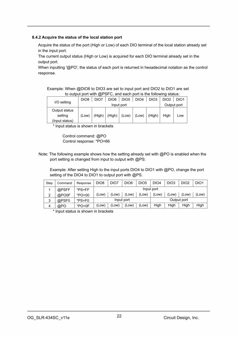
8.4.2 Acquire the status of the local station port
Acquire the status of the port (High or Low) of each DIO terminal of the local station already set
in the input port.
The current output status (High or Low) is acquired for each DIO terminal already set in the
output port.
When inputting '@PO', the status of each port is returned in hexadecimal notation as the control
response.
Example: When @DIO8 to DIO3 are set to input port and DIO2 to DIO1 are set
to output port with @PSFC, and each port is the following status:
I/O settingDIO8 DIO7 DIO6 DIO5 DIO4 DIO3 DIO2 DIO1
Input port Output port
Output status
setting
(Input status)
(Low) (High) (High) (Low) (Low) (High) High Low
* Input status is shown in brackets
Control command: @PO
Control response: *PO=66
Note: The following example shows how the setting already set with @PO is enabled when the
port setting is changed from input to output with @PS:
Example: After setting High to the input ports DIO4 to DIO1 with @PO, change the port
setting of the DIO4 to DIO1 to output port with @PS.
Step Command Response DIO8 DIO7 DIO6 DIO5 DIO4 DIO3 DIO2 DIO1
1 @PSFF *PS=FF Input port
2 @PO0F *PO=00 (Low) (Low) (Low) (Low) (Low) (Low) (Low) (Low)
3 @PSF0 *PS=F0 Input port Output port
4 @PO *PO=0F (Low) (Low) (Low) (Low) High High High High
* Input status is shown in brackets

OG_SLR-434SC_v11e Circuit Design, Inc.23
8.5 “@PT” Set and acquire the target station port status
8.5.1 Acquire the status of the target station port
Acquire the status of the port (High or Low) of each DIO terminal of the target station already set
in the input port.
The current output status is acquired for the DIO terminal already set in the output port.
NOTE
With the control response, the status of the DIO terminals of the local station are output.
The status of the DIO terminals of the target station can be acquired with the '*PR' response
(See "8.8 Contact function responses").
Example: When local station DIO terminals @DIO8 to DIO3 are set to input port and DIO2
to DIO1 are set to output port with @PSFC, and the port of each DIO terminal is
the following status:
I/O settingDIO8 DIO7 DIO6 DIO5 DIO4 DIO3 DIO2 DIO1
Input port Output port
Output status setting
(Input status)*(Low) (High) (High) (Low) (Low) (High) High Low
* Input status is shown in brackets
Control command: @PT
Control response:*PT=66 (Status of the local station)
Response from target station: *PR=040200 (When the target station ID is 02 and the port
status is 00.)
8.5.2 Set the status of the target station port
Set the status of the port for each DIO terminal of the target station already set in the output port.
The setting for the DIO terminal set for the input port can be either High or Low.
Input the 2-character ASCII code (Hex) after ‘@PT’ to set the port status.
The /W option cannot be used.
Example: When target station DIO terminals @DIO8 to DIO3 are set to output port
and DIO2 to DIO1 are set to input port with @PS03, and the port status of
each DIO terminal of the target station is set as follows:
Target station I/O settingDIO8 DIO7 DIO6 DIO5 DIO4 DIO3 DIO2 DIO1
Output port Input port
Output status setting of
the target station
(Input status)*
Low High High Low Low High (Low) (Low)
* Input status is shown in brackets
Control command: @PT64 (The same if @PT65, @PT66, or @PT67 are set.)
Control response: *PT=64
Response from target station: *PR=040264 (When the target station ID is 02 and the port
status is 64.)
* If '@PT##' is executed while the specified times transmission mode when changing input ports
is set ('@PM01' to '@PM05'), transmission to the target station is performed the specified
number of times, however, in this case, any response is not returned from the target station.

OG_SLR-434SC_v11e Circuit Design, Inc.24
8.6 “@PM” Set contact function communication mode
You can set the following 3 types of communication mode for the contact function.
Specified times transmission mode when changing input ports (LoRa/FSK command mode)
One-way continuous transmission mode (FSK command mode only)
Two-way continuous communication mode (FSK command mode only)
The default setting at shipment is ‘0’‘0’.For data communication with the @DT command, use the default setting.
8.6.1 Specified times transmission mode when changing input ports (LoRa/FSK commandmode)
A mode for transmitting the input port status of the local station to a target station the specified
number of times when changing any of the DIO terminals (High → Low or Low → High) already set
in the input port.
For example, first set DIO1 of the local station to input port and DIO1 of the target station to output
port.
When the status of the DIO1 of the local station changes, the information on the change is
transmitted to the target station and when the target station receives it, the output of the DIO1 of
the target station changes.
(As for the output ports of the local station, the output status is transmitted to the target station.)
Input the 2-character ASCII code after ‘@PM’ to set the number of times to transmit (maximum 5
times).
By setting also the target station in this mode, the input port status of both stations can be sent to
each other. For example, set DIO terminals DIO8 to DIO5 of the local station to input port, DIO4 to
DIO1 to output port, DIO terminals DIO8 to DIO5 of the target station to output port, and DIO4 to
DIO1 to input port. However, there is a possibility that communication is not established when both
station transmit at the same time or one transmits while the other is transmitting.
Values: ‘0’ ‘1’: Transmit once
‘0’ ‘2’: Transmit twice
‘0’ ‘3’: Transmit 3 times
‘0’ ‘4’: Transmit 4 times
‘0’ ‘5’: Transmit 5 times
Example: Change to 03 (Transmit 3 times)
Control command: @PM03
Control response: *PM=03

OG_SLR-434SC_v11e Circuit Design, Inc.25
8.6.2 One-way continuous transmission mode (FSK command mode only)
A mode for continuously transmitting the input port status of the local station already set in the
input port to a target station.
It can be used for applications where all the DIO terminals of the local station are set to input
ports and all the DIO terminals of the target station are set to output ports, to change the status
of the corresponding DIO terminal of the target station when the status of the DIO terminals of
the local station are transmitted continuously.
The transmission interval is about 50 ms, and if a situation where the contact status sent by the
local station cannot be received by the target station continues for 1 s, the status of the DIO
terminal of the target station already set in the output port changes to the factory default Low or
the status set with @PO.
To enable this mode, set the local station to ‘@PM10'.
Be sure to set the target station to “PM00”.
Example: Control command: @PM10
Control response: *PM=10
8.6.3 Two-way continuous communication mode (FSK command mode only)
A mode for two-way continuous transmission of the input port status of the local station to the
target station, and the input port status of the target station to the local station.
For example, first set DIO terminals DIO8 to DIO5 of the local station to input port, DIO4 to DIO1
to output port, DIO terminals DIO8 to DIO5 of the target station to output port, and DIO4 to DIO1
to input port. It can be used for applications with two-way continuous communication to send the
status of the input port of the DIO terminal of the local station to the output port of the target
station, and the status of the input port of the target station to the output port of the local station.
The transmission interval is about 110 ms (the interval from transmission of the contact status of
the local station to the target station to reception of the contact status from the target station),
and if a situation where the contact status from the target station cannot be received continues
for 1 s, the status of the DIO terminal of the local station already set in the output port changes to
the factory default Low or the status set with @PO.
To enable this mode, set the local station to ‘@PM20'.
Be sure to set the target station to “PM00”.
Example: Control command: @PM20
Control response: *PM=20
8.7 “@PF” Set output port holding time
When contact information is sent in the specified times transmission mode or with the '@PT##'
command, the target station can set an output holding time to keep the received contact status.
This setting is not available when port status is set with '@PO##' and when the communication
mode is set to the one-way continuous transmission mode or the two-way continuous
transmission mode.
The setting range is from 0.1 seconds (0001) to 6553.5 seconds (FFFF).
The factory setting is 0000 (no time restriction).

OG_SLR-434SC_v11e Circuit Design, Inc.26
Input the 4-character ASCII code (Hex) after ‘@PF’ to set the output holding time.
Example) Device 1 inputs contact signal and Device 2 outputs it with the output holding time of30 seconds.
Device 1 Device 2
'@PM01'(Transmit once when changing input ports)
'@PM00' (Contact communication mode OFF)'@PF012C' (30 seconds= 012C in hex)
Note:When the status of any of the input ports changes, the status information of other ports is alsotransmitted, resulting that the status of the ports that did not change is also output as shownbelow.
8.8 Contact function responses
When communicating using the contact function, a response in the following format is output to
the UART (only when the CTS terminal is set to Low) when any contact information is received.
8.8.1 "PR" response
The response contents are represented by function codes.
Response basic format
Prefix + response name + [=] + function code + Target station ID + contact data + [CR] + [LF]
Prefix: ‘*’ = 2Ah, a code that indicates the start of the response string.
Response name: The 2 characters “PR”.
Function code: Represented by a 2-character ASCII code. See the table below.
Target station ID: Represented by a 2-character ASCII code. See "2.6 "@DI" Set Target station
ID."
Contact data: Represented by a 2-character ASCII code.

OG_SLR-434SC_v11e Circuit Design, Inc.27
Function
codeContent
Response output at:
Local station Target station
“01” A response output at the target station when the local station sends
contact information with @PT and the target station receives it.
(See "8.5.1 Acquire the status of the target station port”)
○
“02” A response output at the target station when the local station sends
contact information to set with @PT and the target station receives it.
(See “8.5.2 Set the status of the target station port”)
○
“03” A response output at the target station when the local station which is
set to the specified times transmission mode sends contact
information and the target station receives it.
(See “8.6.1 Specified times transmission mode when changing input
ports")
○
“04” A response output at the local station when it acquires the target
station port status or sets the target station port status with @PT and
receives an acknowledgement from the target station.
(See “8.5.1 Acquire the status of the target station port” and “8.5.2 Set
the status of the target station port”)
○
“05” A response output at the target station when the local station which is
set to the one-way continuous transmission mode sends contact
information and the target station receives it.
(See “8.6.2 One-way continuous transmission mode”)
○
“06” A response output at the target station when the local station which is
set to the two-way continuous communication mode sends contact
information and the target station receives it.
(See “8.6.3 Two-way continuous communication mode”)
○
“07” A response output at the local station when it is set to the two-way
continuous communication mode and receives an contact information
from the target station.
(See “8.6.3 Two-way continuous communication mode”)
○
“08” A response output at the target station when the local station which is
set to the specified times transmission mode sends contact
information to set with @PT and the target station receives it.
(See “8.5.2 Set the status of the target station port”)
○
“10” A response output at the target station when the local station sends its
own Unique ID with @PIT and the target station receives it.
(See " 8.2.4 Receive the Unique ID of the target station and set it to
the local station”)
○

OG_SLR-434SC_v11e Circuit Design, Inc.28
8.8.2 'PD' response
When transmitting in the Specified times transmission mode, a response in the following format
is output to the UART of the local station.
Response basic format
Prefix + response name + [=] + contact data + [CR] + [LF]
Prefix: ‘*’ = 2Ah, a code that indicates the start of the response string.
Response name: The 2 characters “PD”.
Contact data: The status of the input/output ports of the local station is represented by a 2-
character ASCII code.
8.8.3 Combination of the 'PR' and 'PD' responses
The table below shows the combination example of PR and PD responses, when
communicating between two SLR-434M devices using the @PT command and the contact
function communication modes.
In the following example, Device 1 is set to any of the communication modes with the @PMcommand and Device 2 is set to 'PM00' (Contact function communication OFF).
Device 1
(Local station Eqipment ID="xx", Target station ID="yy")
Device 2
(Local station Eqipment ID="yy",
Target station ID="xx")
Communication
mode settingBehavior
Response
output example
Communication
mode setting
Response output
example
@PM00
'@PT' command
transmission
(acquire the status of
target station port)*PR=04yy$$
@PM00
*PR=01xx&&
'@PT##’ command
transmission
(set the status of target
station port)
*PR=02xx##
@PM01
:
@PM05
Transmission when
changing input ports*PD=&&
*PR=03xx&&(outputs the specified
number of times)
'@PT##' command
transmission
*PR=08xx##(outputs the specified
number of times)
@PM10One-way continuous
transmission*PR=05xx&&
@PM20Two-way continuous
transmission*PR=07yy$$ *PR=06xx&&
"&&" is the status of the input/output ports of Device 1 and "$$" is the status of the input/outputports of Device 2.

OG_SLR-434SC_v11e Circuit Design, Inc.29
9. Command list
Frequency channel setting (Factory setting: "4A" 434.000 MHz)Item Command format Response format Setting value / Error description
Setting command @CH## *CH=##
"00" to "88"Setting command(save the value)
@CH##/W*WR=PS*CH=##
Acquire the setting value @CH *CH=##
Error response*ER=01 Command error*ER=02 Setting value error*ER=03 Command format error
Radio communication mode setting (Factory setting: "03" LoRa command mode)Item Command format Response format Setting value / Error description
Setting command @MO## *MO=## "00":FSK binary mode"01":FSK command mode"02":LoRa binary mode"03":LoRa command mode"04":Air monitor mode
Setting command(save the value)
@MO##/W*WR=PS*MO=##
Acquire the setting value @MO *MO=##
Error response*ER=01 Command error*ER=02 Setting value error*ER=03 Command format error
Number of chips setting with LoRa modulation (Factory setting: "00" 128 chips)Item Command format Response format Setting value / Error description
Setting command @SF## *SF=##"00": 128 chips, "03":1024 chips"01": 256 chips, "04":2048 chips"02": 512 chips, 05":4096 chips
Setting command(save the value)
@SF##/W*WR=PS*SF=##
Acquire the setting value @SF *SF=##
Error response*ER=01 Command error*ER=02 Setting value error*ER=03 Command format error
Equipment ID setting (Factory setting: "01" Equipment ID=1)Item Command format Response format Setting value / Error description
Setting command @EI## *EI=##
"00" to "FF"Setting command(save the value)
@EI##/W*WR=PS*EI=##
Acquire the setting value @EI *EI=##
Error response*ER=01 Command error*ER=03 Command format error
Target station ID setting (Factory setting: "01" Target station ID=1)Item Command format Response format Setting value / Error description
Setting command @DI## *DI=##
"00" to "FF"Setting command(save the value)
@DI##/W*WR=PS*DI=##
Acquire the setting value @DI *DI=##
Error response*ER=01 Command error*ER=03 Command format error

OG_SLR-434SC_v11e Circuit Design, Inc.30
Group ID setting (Factory setting: "00" Group ID=0)Item Command format Response format Setting value / Error description
Setting command @GI## *GI=##
"00" to "FF"Setting command(save the value)
@GI##/W*WR=PS*GI=##
Acquire the setting value @GI *GI=##
Error response*ER=01 Command error*ER=03 Command format error
User ID setting (Factory setting: "0000" User ID=0000)Item Command format Response format Setting value / Error description
Setting command(save the value)
@UI####,XXXX*WR=PS*UI=#### "0000" to "FFFF"
XXXX is a password.Acquire the setting value @UI *UI=####
Error response*ER=01 Command error*ER=03 Command format error*ER=04 Password error
Acquisition of RSSI for the last data receivedItem Command format Response format Setting value / Error description
Acquire the setting value @RS *RS=###dBm
Acquisition of current RSSIItem Command format Response format Setting value / Error description
Acquire the setting value @RA *RA=###dBm
Error response *ER=05 Device is not in reception mode.
RSSI output ON/OFF during carrier sensing (Factory setting: "00" RSSI output OFF)Item Command format Response format Setting value / Error description
Setting command @CR## *CR=##
"00":RSSI output OFF"FF":RSSI output ON
Setting command(save the value)
@CI##/W*WR=PS*CI=##
Acquire the setting value @CR *CR=##
Error response*ER=01 Command error*ER=02 Setting value error*ER=03 Command format error
Acquisition of firmware versionItem Command format Response format Setting value / Error description
Acquire the setting value@FV *FV=#.###,SLR-434M@VR *VR=SLR-434M_V#R###
Acquisition of serial numberItem Command format Response format Setting value / Error description
Acquire the setting value @SN *SN=$#######

OG_SLR-434SC_v11e Circuit Design, Inc.31
Input / Output port setting (Factory setting: "FF" All DIO terminals are input.)Item Command format Response format Setting value / Error description
Setting command @PS## *PS=##"00","01","02","03","0C","0D","0E","0F","F0","F1","F2","F3","FC","FD","FE","FF"
Setting command(save the value)
@PS##/W*WR=PS*PS=##
Acquire the setting value @PS *PS=##
Error response*ER=01 Command error
*ER=03 Command format error
Acquisition/setting of local station port status (Factory setting: "00")Item Command format Response format Setting value / Error description
Setting command @PO## *PO=##
"00" to "FF"Setting command(save the value)
@PO##/W*WR=PS*PO=##
Acquire the setting value @PO *PO=##
Error response*ER=01 Command error*ER=03 Command format error
Acquisition/setting of target station port statusItem Command format Response format Setting value / Error description
Setting command @PT## *PT## "00" to "FF"
Acquire the setting value @PT *PT##
Port status of the local station:"00" to "FF"
(Target port status can be acquiredwith *PR)
Error response*ER=01 Command error*ER=03 Command format error
Contact function communication mode setting (Factory setting:"00" Auto transmission OFF)Item Command format Response format Setting value / Error description
Setting command @PM## *PM=## Auto transmission OFF: "00"Specified times transmission: "01" to "05"One-way continuous transmission: "10"Two-way continuous transmission: "20"
Setting command(save the value)
@PM##/W*WR=PS*PM=##
Acquire the setting value @PM *PM=##
Error response*ER=01 Command error*ER=03 Command format error
Output port holding time setting (Factory setting: "0000" No time restriction)Item Command format Response format Setting value / Error description
Setting command @PF#### *PM=####
"0000" to "FFFF"(1 count = approx. 0.1 s)
Setting command(save the value)
@PF####/W*WR=PS*PM=####
Acquire the setting value @PF *PM=####
Error response*ER=01 Command error
*ER=03 Command format error
Unique ID setting for contact function (Factory setting: "0000" Not using Unique ID)Item Command format Response format Setting value / Error description
Setting cancel @PIC*WR=PS*PI=000000
"000000" : Not using Unique ID
Setting command @PIS*WR=PS*PI=######
"000001" to "98967F"(S/No. *0000001 to 9999999)
Set to Ready mode @PIR *PI=Ready
Transmit the setting value @PIT *PI=######
Check the setting value @PI *PI=######
Error response*ER=01 Command error*ER=03 Command format error
OG_SLR-434SC_v11e Circuit Design, Inc.32
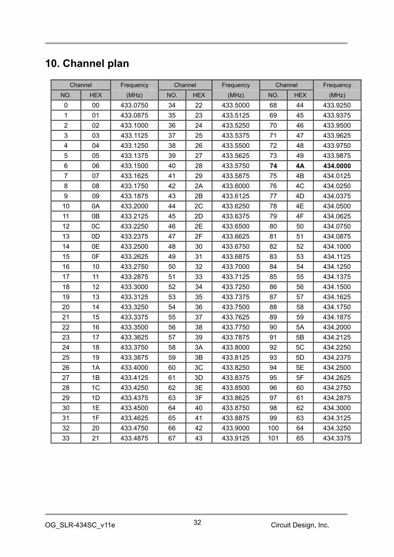
10. Channel plan
Channel Frequency Channel Frequency Channel Frequency
NO. HEX (MHz) NO. HEX (MHz) NO. HEX (MHz)
0 00 433.0750 34 22 433.5000 68 44 433.9250
1 01 433.0875 35 23 433.5125 69 45 433.9375
2 02 433.1000 36 24 433.5250 70 46 433.9500
3 03 433.1125 37 25 433.5375 71 47 433.9625
4 04 433.1250 38 26 433.5500 72 48 433.9750
5 05 433.1375 39 27 433.5625 73 49 433.9875
6 06 433.1500 40 28 433.5750 74 4A 434.0000
7 07 433.1625 41 29 433.5875 75 4B 434.0125
8 08 433.1750 42 2A 433.6000 76 4C 434.0250
9 09 433.1875 43 2B 433.6125 77 4D 434.0375
10 0A 433.2000 44 2C 433.6250 78 4E 434.0500
11 0B 433.2125 45 2D 433.6375 79 4F 434.0625
12 0C 433.2250 46 2E 433.6500 80 50 434.0750
13 0D 433.2375 47 2F 433.6625 81 51 434.0875
14 0E 433.2500 48 30 433.6750 82 52 434.1000
15 0F 433.2625 49 31 433.6875 83 53 434.1125
16 10 433.2750 50 32 433.7000 84 54 434.1250
17 11 433.2875 51 33 433.7125 85 55 434.1375
18 12 433.3000 52 34 433.7250 86 56 434.1500
19 13 433.3125 53 35 433.7375 87 57 434.1625
20 14 433.3250 54 36 433.7500 88 58 434.1750
21 15 433.3375 55 37 433.7625 89 59 434.1875
22 16 433.3500 56 38 433.7750 90 5A 434.2000
23 17 433.3625 57 39 433.7875 91 5B 434.2125
24 18 433.3750 58 3A 433.8000 92 5C 434.2250
25 19 433.3875 59 3B 433.8125 93 5D 434.2375
26 1A 433.4000 60 3C 433.8250 94 5E 434.2500
27 1B 433.4125 61 3D 433.8375 95 5F 434.2625
28 1C 433.4250 62 3E 433.8500 96 60 434.2750
29 1D 433.4375 63 3F 433.8625 97 61 434.2875
30 1E 433.4500 64 40 433.8750 98 62 434.3000
31 1F 433.4625 65 41 433.8875 99 63 434.3125
32 20 433.4750 66 42 433.9000 100 64 434.3250
33 21 433.4875 67 43 433.9125 101 65 434.3375

OG_SLR-434SC_v11e Circuit Design, Inc.33
Channel Frequency Channel Frequency Channel Frequency
NO. HEX (MHz) NO. HEX (MHz) NO. HEX (MHz)
102 66 434.3500 114 72 434.5000 126 7E 434.6500
103 67 434.3625 115 73 434.5125 127 7F 434.6625
104 68 434.3750 116 74 434.5250 128 80 434.6750
105 69 434.3875 117 75 434.5375 129 81 434.6875
106 6A 434.4000 118 76 434.5500 130 82 434.7000
107 6B 434.4125 119 77 434.5625 131 83 434.7125
108 6C 434.4250 120 78 434.5750 132 84 434.7250
109 6D 434.4375 121 79 434.5875 133 85 434.7375
110 6E 434.4500 122 7A 434.6000 134 86 434.7500
111 6F 434.4625 123 7B 434.6125 135 87 434.7625
112 70 434.4750 124 7C 434.6250 136 88 434.7750
113 71 434.4875 125 7D 434.6375
*The channel is set to No. 74 (434.000 MHz) for shipment.*If you intend to use several SLR-434M units in the same area, use a channel plan that takes intoaccount radio interference due to third-order intermodulation.
Circuit Design provides a computational tool on our website for creating channel plans that avoid
interference due to third-order intermodulation.
Calculation tool: http://www.cdt21.com/resources/siryo6.asp
OG_SLR-434SC_v11e Circuit Design, Inc.34
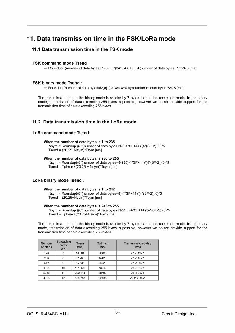
11. Data transmission time in the FSK/LoRa mode
11.1 Data transmission time in the FSK mode
FSK command mode Tsend :≒ Roundup {(number of data bytes+7)/52,0}*(34*8/4.8+0.9)+(number of data bytes+7)*8/4.8 [ms]
FSK binary mode Tsend :≒ Roundup {number of data bytes/52,0}*(34*8/4.8+0.9)+number of data bytes*8/4.8 [ms]
The transmission time in the binary mode is shorter by 7 bytes than in the command mode. In the binarymode, transmission of data exceeding 255 bytes is possible, however we do not provide support for thetransmission time of data exceeding 255 bytes.
11.2 Data transmission time in the LoRa mode
LoRa command mode Tsend:
When the number of data bytes is 1 to 235Nsym = Roundup {(8*(number of data bytes+15)-4*SF+44)/(4*(SF-2)),0}*5Tsend = (20.25+Nsym)*Tsym [ms]
When the number of data bytes is 236 to 255Nsym = Roundup{(8*(number of data bytes+8-235)-4*SF+44)/(4*(SF-2)),0}*5Tsend = Tplmax+(20.25 + Nsym)*Tsym [ms]
LoRa binary mode Tsend :
When the number of data bytes is 1 to 242Nsym = Roundup{(8*(number of data bytes+8)-4*SF+44)/(4*(SF-2)),0}*5Tsend = (20.25+Nsym)*Tsym [ms]
When the number of data bytes is 243 to 255Nsym = Roundup {(8*(number of data bytes+1-235)-4*SF+44)/(4*(SF-2)),0}*5Tsend = Tplmax+(20.25+Nsym)*Tsym [ms]
The transmission time in the binary mode is shorter by 7 bytes than in the command mode. In the binarymode, transmission of data exceeding 255 bytes is possible, however we do not provide support for thetransmission time of data exceeding 255 bytes.
Numberof chips
SpreadingfactorSF
Tsym(ms)
Tplmax(ms)
Transmission delay(ms)
128 7 16.384 8606 22 to 1222
256 8 32.768 14426 22 to 1522
512 9 65.536 24920 22 to 3022
1024 10 131.072 43942 22 to 5222
2048 11 262.144 78709 22 to 9372
4096 12 524.288 141689 22 to 22022

OG_SLR-434SC_v11e Circuit Design, Inc.35
Important note:
The SLR-434M uses the packet communication function of the internal RF IC. The payload length of onepacket is up to 60 bytes in the FSK mode and up to 250 bytes in the LoRa mode.
When transmitting data in the command mode, since 15 bytes are added to the user data as Equipment ID,control commands and so on, the number of user data per packet is up to 45 bytes in the DSK mode andup to 235 bytes in the LoRa mode.
For example, in the FSK mode, the user data of up to 45 bytes is sent in one packet, and the data of 46 to90 bytes is sent in two packets. A 'Hi' pulse is output to the TXLED between packets.

OG_SLR-434SC_v11e Circuit Design, Inc.36
11.3 Data transmission time
1 -6 59.2 741 1319 2310 4620 7930 15860 70 63 232 2953 5087 8864 15761 28901 52560
2 -5 60.9 741 1319 2638 4620 9241 15860 71 64 233 3035 5087 8864 15761 28901 52560
3 -4 62.6 823 1483 2638 4620 9241 18481 72 65 235 3035 5251 9191 16417 28901 52560
4 -3 64.2 823 1483 2638 5276 9241 18481 73 66 237 3117 5251 9191 16417 28901 55181
5 -2 65.9 823 1483 2638 5276 9241 18481 74 67 238 3117 5251 9191 16417 30212 55181
6 -1 67.6 905 1647 2966 5276 10551 18481 75 68 240 3117 5415 9191 16417 30212 55181
7 0 69.2 905 1647 2966 5276 10551 18481 76 69 242 3199 5415 9519 17072 30212 55181
8 1 70.9 987 1647 2966 5931 10551 21103 77 70 243 3199 5415 9519 17072 30212 55181
9 2 72.6 987 1810 3293 5931 10551 21103 78 71 245 3281 5579 9519 17072 31523 57803
10 3 74.2 987 1810 3293 5931 10551 21103 79 72 247 3281 5579 9847 17072 31523 57803
11 4 75.9 1069 1810 3293 5931 11862 21103 80 73 248 3281 5579 9847 17727 31523 57803
12 5 77.6 1069 1974 3293 6586 11862 21103 81 74 250 3363 5743 9847 17727 31523 57803
13 6 79.2 1151 1974 3621 6586 11862 23724 82 75 252 3363 5743 9847 17727 31523 57803
14 7 80.9 1151 1974 3621 6586 11862 23724 83 76 253 3445 5743 10174 17727 32834 60424
15 8 82.6 1151 2138 3621 6586 13173 23724 84 77 255 3445 5906 10174 18383 32834 60424
16 9 84.2 1233 2138 3949 7242 13173 23724 85 78 257 3445 5906 10174 18383 32834 60424
17 10 85.9 1233 2138 3949 7242 13173 23724 86 79 258 3527 5906 10502 18383 32834 60424
18 11 87.6 1315 2302 3949 7242 13173 26345 87 80 260 3527 6070 10502 18383 34144 60424
19 12 89.2 1315 2302 3949 7242 13173 26345 88 81 262 3609 6070 10502 19038 34144 63046
20 13 90.9 1315 2302 4276 7897 14483 26345 89 82 263 3609 6070 10502 19038 34144 63046
21 14 92.6 1397 2466 4276 7897 14483 26345 90 83 265 3609 6234 10830 19038 34144 63046
22 15 94.2 1397 2466 4276 7897 14483 26345 91 84 267 3690 6234 10830 19038 34144 63046
23 16 95.9 1479 2466 4604 7897 14483 28967 92 85 268 3690 6234 10830 19694 35455 63046
24 17 97.6 1479 2630 4604 8552 15794 28967 93 86 270 3772 6398 11158 19694 35455 65667
25 18 99.2 1479 2630 4604 8552 15794 28967 94 87 272 3772 6398 11158 19694 35455 65667
26 19 101 1561 2630 4604 8552 15794 28967 95 88 273 3772 6398 11158 19694 35455 65667
27 20 103 1561 2793 4932 8552 15794 28967 96 89 275 3854 6562 11158 20349 36766 65667
28 21 104 1642 2793 4932 9208 15794 31588 97 90 277 3854 6562 11485 20349 36766 65667
29 22 106 1642 2793 4932 9208 17105 31588 98 91 278 3936 6562 11485 20349 36766 68289
30 23 108 1642 2957 5259 9208 17105 31588 99 92 280 3936 6726 11485 20349 36766 68289
31 24 109 1724 2957 5259 9208 17105 31588 100 93 282 3936 6726 11813 21004 36766 68289
32 25 111 1724 2957 5259 9863 17105 31588 101 94 283 4018 6726 11813 21004 38076 68289
33 26 113 1806 3121 5259 9863 18416 34210 102 95 285 4018 6889 11813 21004 38076 68289
34 27 114 1806 3121 5587 9863 18416 34210 103 96 287 4100 6889 11813 21004 38076 70910
35 28 116 1806 3121 5587 9863 18416 34210 104 97 288 4100 6889 12141 21660 38076 70910
36 29 118 1888 3285 5587 10519 18416 34210 105 98 348 4100 7053 12141 21660 39387 70910
37 30 119 1888 3285 5915 10519 18416 34210 106 99 349 4182 7053 12141 21660 39387 70910
38 31 121 1970 3285 5915 10519 19726 36831 107 100 351 4182 7053 12468 21660 39387 70910
39 32 123 1970 3449 5915 10519 19726 36831 108 101 353 4264 7217 12468 22315 39387 73531
40 33 124 1970 3449 5915 11174 19726 36831 109 102 354 4264 7217 12468 22315 39387 73531
41 34 126 2052 3449 6242 11174 19726 36831 110 103 356 4264 7217 12468 22315 40698 73531
42 35 128 2052 3613 6242 11174 21037 36831 111 104 358 4346 7381 12796 22315 40698 73531
43 36 129 2134 3613 6242 11174 21037 39453 112 105 359 4346 7381 12796 22970 40698 73531
44 37 131 2134 3613 6570 11829 21037 39453 113 106 361 4428 7381 12796 22970 40698 76153
45 38 133 2134 3777 6570 11829 21037 39453 114 107 363 4428 7545 13124 22970 42009 76153
46 39 134 2216 3777 6570 11829 21037 39453 115 108 364 4428 7545 13124 22970 42009 76153
47 40 136 2216 3777 6570 11829 22348 39453 116 109 366 4510 7545 13124 23626 42009 76153
48 41 138 2298 3940 6898 12485 22348 42074 117 110 368 4510 7709 13124 23626 42009 76153
49 42 139 2298 3940 6898 12485 22348 42074 118 111 369 4592 7709 13451 23626 42009 78774
50 43 141 2298 3940 6898 12485 22348 42074 119 112 371 4592 7709 13451 23626 43319 78774
51 44 143 2380 4104 7225 12485 23658 42074 120 113 373 4592 7873 13451 24281 43319 78774
52 45 144 2380 4104 7225 13140 23658 42074 121 114 374 4674 7873 13779 24281 43319 78774
53 46 203 2462 4104 7225 13140 23658 44696 122 115 376 4674 7873 13779 24281 43319 78774
54 47 205 2462 4268 7225 13140 23658 44696 123 116 378 4755 8036 13779 24281 44630 81396
55 48 207 2462 4268 7553 13140 23658 44696 124 117 379 4755 8036 13779 24936 44630 81396
56 49 208 2544 4268 7553 13795 24969 44696 125 118 381 4755 8036 14107 24936 44630 81396
57 50 210 2544 4432 7553 13795 24969 44696 126 119 383 4837 8200 14107 24936 44630 81396
58 51 212 2626 4432 7881 13795 24969 47317 127 120 384 4837 8200 14107 24936 44630 81396
59 52 213 2626 4432 7881 13795 24969 47317 128 121 386 4919 8200 14434 25592 45941 84017
60 53 215 2626 4596 7881 14451 26280 47317 129 122 388 4919 8364 14434 25592 45941 84017
61 54 217 2707 4596 7881 14451 26280 47317 130 123 389 4919 8364 14434 25592 45941 84017
62 55 218 2707 4596 8208 14451 26280 47317 131 124 391 5001 8364 14434 25592 45941 84017
63 56 220 2789 4760 8208 14451 26280 49938 132 125 393 5001 8528 14762 26247 47251 84017
64 57 222 2789 4760 8208 15106 26280 49938 133 126 394 5083 8528 14762 26247 47251 86639
65 58 223 2789 4760 8536 15106 27591 49938 134 127 396 5083 8528 14762 26247 47251 86639
66 59 225 2871 4923 8536 15106 27591 49938 135 128 398 5083 8692 15090 26247 47251 86639
67 60 227 2871 4923 8536 15106 27591 49938 136 129 399 5165 8692 15090 26903 47251 86639
68 61 228 2953 4923 8536 15761 27591 52560 137 130 401 5165 8692 15090 26903 48562 86639
69 62 230 2953 5087 8864 15761 28901 52560 138 131 403 5247 8856 15090 26903 48562 89260
バイナリ
モード
送信時間 Tsend [ms]データ数(By te)
256
chip
512
chip
1024
chip
4096
chip
FSK128
chip
FSKバイナリ
モード
コマンド
モード512
chip
1024
chip
2048
chip
データ数(By te) 送信時間 Tsend [ms]
LoRa LoRa
4096
chip
128
chip
256
chip
コマンド
モード2048
chip
Binarymode
Binarymode
Commandmode
Commandmode
Data [byte] Data [byte]Transmission time Transmission time

OG_SLR-434SC_v11e Circuit Design, Inc.37
139 132 404 5247 8856 15417 26903 48562 89260 202 195 567 7295 12296 21316 37388 66912 120717
140 133 406 5247 8856 15417 27558 48562 89260 203 196 569 7377 12296 21316 37388 66912 123339
141 134 408 5329 9019 15417 27558 49873 89260 204 197 570 7377 12460 21316 38044 68223 123339
142 135 409 5329 9019 15745 27558 49873 89260 205 198 572 7377 12460 21643 38044 68223 123339
143 136 411 5411 9019 15745 27558 49873 91881 206 199 574 7459 12460 21643 38044 68223 123339
144 137 413 5411 9183 15745 28213 49873 91881 207 200 575 7459 12624 21643 38044 68223 123339
145 138 414 5411 9183 15745 28213 49873 91881 208 201 577 7541 12624 21643 38699 68223 125960
146 139 416 5493 9183 16073 28213 51184 91881 209 202 636 7541 12624 21971 38699 69534 125960
147 140 418 5493 9347 16073 28213 51184 91881 210 203 638 7541 12788 21971 38699 69534 125960
148 141 419 5575 9347 16073 28869 51184 94503 211 204 640 7623 12788 21971 38699 69534 125960
149 142 421 5575 9347 16400 28869 51184 94503 212 205 641 7623 12788 22299 39354 69534 125960
150 143 423 5575 9511 16400 28869 52494 94503 213 206 643 7705 12952 22299 39354 70844 128582
151 144 424 5657 9511 16400 28869 52494 94503 214 207 645 7705 12952 22299 39354 70844 128582
152 145 426 5657 9511 16400 29524 52494 94503 215 208 646 7705 12952 22299 39354 70844 128582
153 146 428 5738 9675 16728 29524 52494 97124 216 209 648 7786 13115 22626 40010 70844 128582
154 147 429 5738 9675 16728 29524 52494 97124 217 210 650 7786 13115 22626 40010 70844 128582
155 148 431 5738 9675 16728 29524 53805 97124 218 211 651 7868 13115 22626 40010 72155 131203
156 149 433 5820 9839 17056 30179 53805 97124 219 212 653 7868 13279 22954 40010 72155 131203
157 150 492 5820 9839 17056 30179 53805 97124 220 213 655 7868 13279 22954 40665 72155 131203
158 151 494 5902 9839 17056 30179 53805 99746 221 214 656 7950 13279 22954 40665 72155 131203
159 152 495 5902 10002 17056 30179 55116 99746 222 215 658 7950 13443 22954 40665 73466 131203
160 153 497 5902 10002 17383 30835 55116 99746 223 216 660 8032 13443 23282 40665 73466 133825
161 154 499 5984 10002 17383 30835 55116 99746 224 217 661 8032 13443 23282 41320 73466 133825
162 155 500 5984 10166 17383 30835 55116 99746 225 218 663 8032 13607 23282 41320 73466 133825
163 156 502 6066 10166 17711 30835 55116 102367 226 219 665 8114 13607 23609 41320 73466 133825
164 157 504 6066 10166 17711 31490 56426 102367 227 220 666 8114 13607 23609 41320 74777 133825
165 158 505 6066 10330 17711 31490 56426 102367 228 221 668 8196 13771 23609 41976 74777 136446
166 159 507 6148 10330 17711 31490 56426 102367 229 222 670 8196 13771 23609 41976 74777 136446
167 160 509 6148 10330 18039 31490 56426 102367 230 223 671 8196 13771 23937 41976 74777 136446
168 161 510 6230 10494 18039 32145 57737 104989 231 224 673 8278 13935 23937 41976 76087 136446
169 162 512 6230 10494 18039 32145 57737 104989 232 225 675 8278 13935 23937 42631 76087 136446
170 163 514 6230 10494 18366 32145 57737 104989 233 226 676 8360 13935 24265 42631 76087 139067
171 164 515 6312 10658 18366 32145 57737 104989 234 227 678 8360 14098 24265 42631 76087 139067
172 165 517 6312 10658 18366 32801 57737 104989 235 228 680 8360 14098 24265 42631 76087 139067
173 166 519 6394 10658 18366 32801 59048 107610 236 229 681 8442 14098 24265 43287 77398 139067
174 167 520 6394 10822 18694 32801 59048 107610 237 230 683 8442 14262 24592 43287 77398 139067
175 168 522 6394 10822 18694 32801 59048 107610 238 231 685 8524 14262 24592 43287 77398 141689
176 169 524 6476 10822 18694 33456 59048 107610 239 232 686 8524 14262 24592 43287 77398 141689
177 170 525 6476 10985 19022 33456 60359 107610 240 233 688 8524 14426 24920 43942 78709 141689
178 171 527 6558 10985 19022 33456 60359 110232 241 234 690 8606 14426 24920 43942 78709 141689
179 172 529 6558 10985 19022 33456 60359 110232 242 235 691 8606 14426 24920 43942 78709 141689
180 173 530 6558 11149 19022 34111 60359 110232 243 236 693 9347 15745 27230 48562 86639 157549
181 174 532 6640 11149 19350 34111 60359 110232 244 237 695 9347 15745 27558 48562 87950 157549
182 175 534 6640 11149 19350 34111 61669 110232 245 238 696 9429 15909 27558 48562 87950 160170
183 176 535 6722 11313 19350 34111 61669 112853 246 239 698 9429 15909 27558 49218 87950 160170
184 177 537 6722 11313 19677 34767 61669 112853 247 240 700 9429 15909 27558 49218 87950 160170
185 178 539 6722 11313 19677 34767 61669 112853 248 241 701 9511 16073 27886 49218 89260 160170
186 179 540 6803 11477 19677 34767 62980 112853 249 242 703 9511 16073 27886 49218 89260 160170
187 180 542 6803 11477 19677 34767 62980 112853 250 243 705 9593 16073 27886 49873 89260 162792
188 181 544 6885 11477 20005 35422 62980 115474 251 244 706 9593 16236 28213 49873 89260 162792
189 182 545 6885 11641 20005 35422 62980 115474 252 245 708 9593 16236 28213 49873 89260 162792
190 183 547 6885 11641 20005 35422 62980 115474 253 246 710 9675 16236 28213 49873 90571 162792
191 184 549 6967 11641 20333 35422 64291 115474 254 247 711 9675 16400 28213 50528 90571 162792
192 185 550 6967 11805 20333 36078 64291 115474 255 248 713 9757 16400 28541 50528 90571 165413
193 186 552 7049 11805 20333 36078 64291 118096 256 249 715 9757 16400 28541 50528 90571 165413
194 187 554 7049 11805 20333 36078 64291 118096 257 250 716 9757 16564 28541 50528 91882 165413
195 188 555 7049 11969 20660 36078 65602 118096 258 251 718 9839 16564 28869 51184 91882 165413
196 189 557 7131 11969 20660 36733 65602 118096 259 252 720 9839 16564 28869 51184 91882 165413
197 190 559 7131 11969 20660 36733 65602 118096 260 253 721 9921 16728 28869 51184 91882 168034
198 191 560 7213 12132 20988 36733 65602 120717 261 254 780 9921 16728 28869 51184 91882 168034
199 192 562 7213 12132 20988 36733 65602 120717 262 255 782 9921 16728 29196 51839 93192 168034
200 193 564 7213 12132 20988 37388 66912 120717
201 194 565 7295 12296 20988 37388 66912 120717
4096
chip
データ数(By te)
FSK
LoRa
送信時間 Tsend [ms]データ数(By te)
バイナリ
モード
コマンド
モード4096
chip
FSKバイナリ
モード
コマンド
モード
LoRa
128
chip
256
chip
512
chip
1024
chip
2048
chip
送信時間 Tsend [ms]
128
chip
256
chip
512
chip
1024
chip
2048
chip
コマンドモードでは1度に255Byteまでしか送信できません。バイナリモードでは
256Byte以上の送信も可能ですが時間についてはサポートしません。
Note: Although the data input buffer of the UART has sufficient area of 256 bytes or more, if youinput long data in the binary mode without using the RTS control signal, buffer over occursand data may be discarded. It is recommended that the data length of one transmission is e256 bytes or less.
Binarymode
Binarymode
Commandmode
Commandmode
Data [byte] Data [byte]Transmission time Transmission time

OG_SLR-434SC_v11e Circuit Design, Inc.38
Revision History
Version Date Description Remark0.91 Feb. 2017 Provisional Edition
1.0 Feb. 20181.1 Sep. 2018 Chapter 11 added
The copyright of this manual belongs to Circuit Design, Inc. Reproduction, duplication or modificationof part or all of this manual without permission is prohibited.