slope design criteria for large open pits - case study
TRANSCRIPT

Slope Design Criteria for Large Open Pits ― Case Study
F. Pothitos Ok Tedi Mining Ltd, Papua New Guinea (formerly Newcrest Mining Ltd, Australia)
T. Li Newcrest Mining Ltd, Australia
Abstract The selection of design criteria for large open pits is an area of ongoing importance and one which must continually be reviewed and improved upon during the lifetime of a mine project. Not only do the design criteria directly impact upon the business case [and longevity] of a mine project but also the safety related geotechnical issues, which must be planned for during the design process. The case study presented, is used to illustrate the criteria and considerations of a large open pit design from an operational perspective. A consistent message is required to be communicated at all stages and levels involving operators, operational engineers, designers and management. This paper presents concepts to help interpret what percentage of pit slope failure is acceptable and the resources required to implement varying inter-ramp slope angles with a certain percentage of planned failure.
1 Introduction The Cadia Hill Open Pit has been in operation since 1997. The current pit measures 1.5 km in diameter and 340 to 500 m deep. The open pit mining rates have been between 40 to 80 mtpa, with ore production at 17 mtpa at 0.77 g/t gold and 0.18% copper. The annual production is approximately 300,000 oz gold and 23,000 t of copper. The mining reserve stands at approximately 120 mt at 0.79 g/t gold and 0.17% copper with six years mine life remaining. The final pit dimension is currently designed to reach a maximum of 720 m deep from the top of the North wall and 560 m from the pit access levels.
The slope performance, in comparison to the original design, has been influenced by a number of unplanned cutbacks associated with geotechnical issues and a few minor slope failures. Following a major cutback to address the instability of the North wall in early 2002, the impact of slope instability on safety and economics of pit mining were assessed, and improvement opportunities were identified.
The Cadia Pit Optimisation Project was initiated in early 2003 in order to re-evaluate the pit designs and staging options (Li et al., 2003). As part of the process it was identified that the existing design criteria could not be applied for steep brittle slopes, and alternate design criteria needed to be developed. This paper details the development of the criteria and their application.
Understanding the application of design criteria in an operating environment can have significant impacts on geotechnical safety related issues and the business case of the project. Understanding when to change the design for both upside and downside risk is critical for the business case of the project, and developing the area of design criteria is essential to the process for mining large open pits. It is also imperative that operators, engineers and management have a uniform understanding of slope design and implementation.
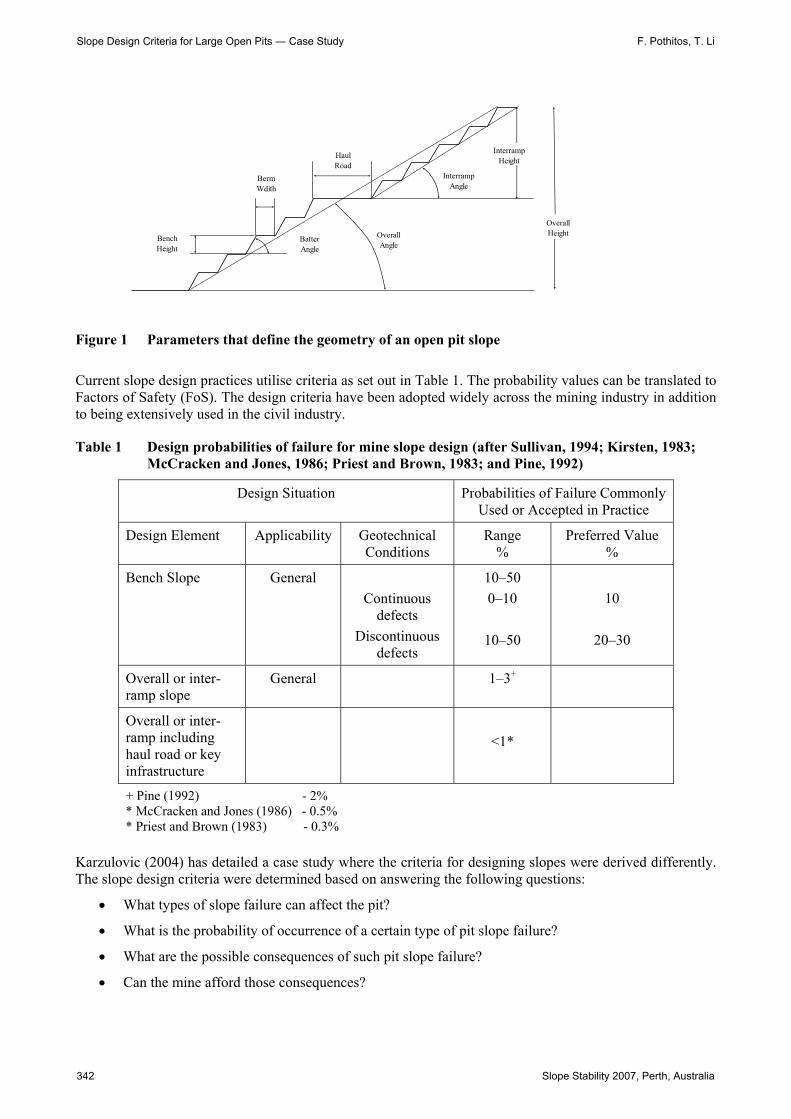
2 Background Slope design comprises several components that are shown in Figure 1, they are: bench, inter-ramp, and overall slope. Depending on the specific site conditions either one or all three elements can be considered for the design. Each slope element has specific design criteria which can be applied.
Slope Stability 2007 — Y. Potvin (ed) ©2007 Australian Centre for Geomechanics, Perth, ISBN 978-0-9756756-8-7
Slope Stability 2007, Perth, Australia 341
https://papers.acg.uwa.edu.au/p/708_21_Pothitos/
BenchHeight
BermWdith
BatterAngle
OverallAngle
HaulRoad
InterrampAngle
InterrampHeight
OverallHeight
Figure 1 Parameters that define the geometry of an open pit slope
Current slope design practices utilise criteria as set out in Table 1. The probability values can be translated to Factors of Safety (FoS). The design criteria have been adopted widely across the mining industry in addition to being extensively used in the civil industry.
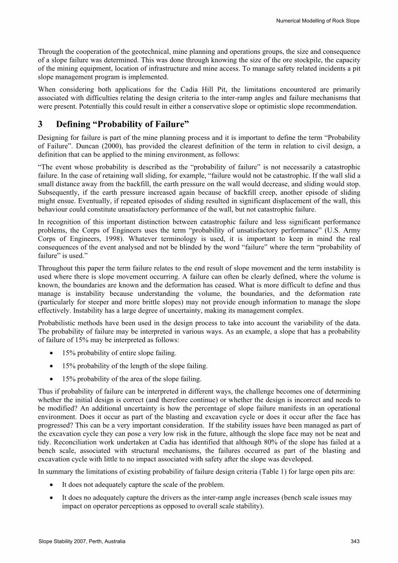
Table 1 Design probabilities of failure for mine slope design (after Sullivan, 1994; Kirsten, 1983; McCracken and Jones, 1986; Priest and Brown, 1983; and Pine, 1992)
Design Situation Probabilities of Failure Commonly Used or Accepted in Practice
Design Element Applicability Geotechnical Conditions
Range %
Preferred Value %
Bench Slope General Continuous
defects Discontinuous
defects
10–50 0–10
10–50
10
20–30
Overall or inter- ramp slope
General 1–3+
Overall or inter- ramp including haul road or key infrastructure
<1*
+ Pine (1992) - 2% * McCracken and Jones (1986) - 0.5% * Priest and Brown (1983) - 0.3%
Karzulovic (2004) has detailed a case study where the criteria for designing slopes were derived differently. The slope design criteria were determined based on answering the following questions:
• What types of slope failure can affect the pit?
• What is the probability of occurrence of a certain type of pit slope failure?
• What are the possible consequences of such pit slope failure?
• Can the mine afford those consequences?
Slope Design Criteria for Large Open Pits ― Case Study F. Pothitos, T. Li
342 Slope Stability 2007, Perth, Australia
Through the cooperation of the geotechnical, mine planning and operations groups, the size and consequence of a slope failure was determined. This was done through knowing the size of the ore stockpile, the capacity of the mining equipment, location of infrastructure and mine access. To manage safety related incidents a pit slope management program is implemented.
When considering both applications for the Cadia Hill Pit, the limitations encountered are primarily associated with difficulties relating the design criteria to the inter-ramp angles and failure mechanisms that were present. Potentially this could result in either a conservative slope or optimistic slope recommendation.
3 Defining “Probability of Failure” Designing for failure is part of the mine planning process and it is important to define the term “Probability of Failure”. Duncan (2000), has provided the clearest definition of the term in relation to civil design, a definition that can be applied to the mining environment, as follows:
“The event whose probability is described as the “probability of failure” is not necessarily a catastrophic failure. In the case of retaining wall sliding, for example, “failure would not be catastrophic. If the wall slid a small distance away from the backfill, the earth pressure on the wall would decrease, and sliding would stop. Subsequently, if the earth pressure increased again because of backfill creep, another episode of sliding might ensue. Eventually, if repeated episodes of sliding resulted in significant displacement of the wall, this behaviour could constitute unsatisfactory performance of the wall, but not catastrophic failure.
In recognition of this important distinction between catastrophic failure and less significant performance problems, the Corps of Engineers uses the term “probability of unsatisfactory performance” (U.S. Army Corps of Engineers, 1998). Whatever terminology is used, it is important to keep in mind the real consequences of the event analysed and not be blinded by the word “failure” where the term “probability of failure” is used.”
Throughout this paper the term failure relates to the end result of slope movement and the term instability is used where there is slope movement occurring. A failure can often be clearly defined, where the volume is known, the boundaries are known and the deformation has ceased. What is more difficult to define and thus manage is instability because understanding the volume, the boundaries, and the deformation rate (particularly for steeper and more brittle slopes) may not provide enough information to manage the slope effectively. Instability has a large degree of uncertainty, making its management complex.
Probabilistic methods have been used in the design process to take into account the variability of the data. The probability of failure may be interpreted in various ways. As an example, a slope that has a probability of failure of 15% may be interpreted as follows:
• 15% probability of entire slope failing.
• 15% probability of the length of the slope failing.
• 15% probability of the area of the slope failing.
Thus if probability of failure can be interpreted in different ways, the challenge becomes one of determining whether the initial design is correct (and therefore continue) or whether the design is incorrect and needs to be modified? An additional uncertainty is how the percentage of slope failure manifests in an operational environment. Does it occur as part of the blasting and excavation cycle or does it occur after the face has progressed? This can be a very important consideration. If the stability issues have been managed as part of the excavation cycle they can pose a very low risk in the future, although the slope face may not be neat and tidy. Reconciliation work undertaken at Cadia has identified that although 80% of the slope has failed at a bench scale, associated with structural mechanisms, the failures occurred as part of the blasting and excavation cycle with little to no impact associated with safety after the slope was developed.
In summary the limitations of existing probability of failure design criteria (Table 1) for large open pits are:
• It does not adequately capture the scale of the problem.
• It does no adequately capture the drivers as the inter-ramp angle increases (bench scale issues may impact on operator perceptions as opposed to overall scale stability).
Numerical Modelling of Rock Slope
Slope Stability 2007, Perth, Australia 343
• The ability to manage geotechnical issues or the skills and resources available to implement a technically correct design are not detailed.
4 Failure Modes Pit slope deformation has generally been well understood for the past several decades. However the mechanisms of the development of slope instability are poorly understood (Sjoberg, 1999). Understanding failure modes is an important component of managing pit slopes. Flatter inter-ramp angles are generally associated with weaker rock masses and thus ductile deformation is more dominant. Steeper inter-ramp angles are generally associated with more competent rock masses and thus brittle deformation is more dominant.
At a bench scale failure mechanisms are generally well understood. The structural controls are often clearly defined, generally comprising discrete structures that traverse the height of the bench. As the slope height increases the failure mechanisms become more complex as our knowledge of the controls becomes less reliable. This is due to additional factors requiring consideration such as rock bridges and the interaction of multiple structures.
Another important consideration associated with failure modes is the momentum of failure and rock fall trajectories. For a hard rock environment, a flatter slope is likely to have a lower momentum and smaller rockfall trajectories. As an example, the Cadia Extended failure (Pothitos et al., 2006), which was captured on film, comprised 1 mt at a design inter-ramp angle of 38°, and moved about 5 m. As the slope angle increased, so did the momentum of the failure and rockfall trajectories. A 150 kt failure in the Cadia Hill Pit (Pothitos et al., 2003) resulted in rock debris being spread over a large area and dispersed a distance of about 60 m from the wall of the working bench. Essentially, the complexity of managing rockfall trajectories increases with steeper slope angles. The flexibility to manage unstable slopes decreases with increasing slope angles. Therefore integrating failure mechanisms as part of the design criteria is important.
A probability of failure of less than 1% for a slope with infrastructure is irrelevant if the infrastructure is primarily susceptible to deformation, which a slope can experience without ultimately failing. There have also been instances where a slope containing a ramp has failed and another ramp has been dozed through the failed material.
Time dependant deformation may not be an issue if the mine or pit slope has a short design life. In addition to the uncertainty of understanding how much deformation a slope can withstand prior to failing, both derivatives of failure mechanisms contribute to the uncertainty of designing the slope.
5 Slope Monitoring Systems to monitor slopes have developed significantly over the past decade. The systems available include robotic prism monitoring, wireline extensometers, slope radar and satellite monitoring, which are all capable of being linked to telemetry systems for live data analysis. In addition to other pit slope management practices the ability to manage slope instability has significantly increased. However there is a risk that current monitoring systems may be used to drive the slope design process or decrease the rigour of slope design required.
Slope design should take into consideration (at the design or redesign stage) the type of monitoring systems required, based on the capabilities of implementing the slope and defining the likely failure mechanisms (Pothitos et al., 2003; Pothitos et al., 2006).
6 Safety Risk Geotechnical safety related issues are present in all elements of slope design: bench, inter-ramp and overall slopes. Each element needs to be addressed at the design stage, however if the pit is at a project stage the safety risks may not be clearly understood and thus not planned and budgeted for. As a consequence it follows that a reduction in slope element angles is likely to affect business targets.
Current slope design criteria do not adequately consider the safety issues from a design perspective, often qualifying the design criteria with the need to implement a rigorous pit slope management program. It is the
Slope Design Criteria for Large Open Pits ― Case Study F. Pothitos, T. Li
344 Slope Stability 2007, Perth, Australia

author’s experience that the complexity of safety related geotechnical issues increases with increasing inter-ramp slope angles. There is also a change in operator perceptions when slopes move from single bench design to double bench design. This is an important inflection point in slope design and occurs at around a 50° inter-ramp angle.
Geotechnical safety related issues need to be incorporated at the design stage to ultimately strive to eliminate rockfall related incidents and to achieve consistent production.
7 Business Risk The Authors will define business risk as the economic consequence associated with managing slope instability and the change in overall slope angles. Often there can be both a large economic consequence as a result of reducing slope angles (downside risk), or increasing slope angles (opportunity risk). It is important that both outcomes are financially evaluated, enabling an informed decision to be made when changing the slope angles. Call (1992) has represented the business impact associated with slope angles in a graph (Figure 2) by showing the increasing cost associated with increasing slope angle together with the increasing value of steepening walls and gaining more ore, or reducing waste, to show the net benefit curve. The inflection point of the net benefit curve shows the optimum slope angle.
05
101520253035404550
35 40 45 50 55
Slope Angle (deg)
Cost
($m
)
CostRevenueNet Benefit
Optimum angle
Figure 2 Cost benefit curve (Call, 1992)
The Call paper discusses the net cost benefit of mining to identify the optimum slope angle; however, this can be difficult to define if the cost of slope remediation activities is an unknown. It is simpler to calculate the direct costs associated with instability. The indirect costs associated with instability are more difficult to quantify and can involve: disruptions to production, operator perceptions, and unfavourable media reports.
Karzulovic (2004) detailed a case study for improving the business through designing slopes based on the volume of the ore stockpile, the time it can supply the mill without any additional ore, and the production capabilities to clean out a slope failure within the time required to deplete the stockpile. The case study highlighted that although the cost of managing the slope failures could be considered high within a yearly budget, in terms of the overall business outcome the benefit substantially outweighed the cost.
8 Resources The key driver to determine what resources are required for an operating mine is the overall business risk. If the business case is founded on the need to manage slope instability, increased slope angles and uncertainty, the following should be considered:
Numerical Modelling of Rock Slope
Slope Stability 2007, Perth, Australia 345
• Geotechnical personnel to implement a pit slope management program and to undertake design work to modify the slope for both upside and downside risk.
• Slope monitoring systems to aid in understanding the slope deformations.
• Small diameter drill rigs used for trim blasting and presplitting, where the primary production blasts use larger diameter drill holes. These resources are likely to be required where the inter-ramp angle increases beyond 47°, to mitigate both bench scale instability and small rockfall debris.
• Smaller excavators to manage smaller failures, as the primary dig units are used to maintain production targets and are also too cumbersome to provide the smoother wall finish required.
• Implementation of support systems to manage smaller rock debris as the slope angle increases, these may comprise meshing, ground support and purpose built catch fences.
• Training and development of personnel.
9 Design Criteria – Case Study The Cadia Hill Pit is comprised predominantly of a hard rock mass with structures, resulting in brittle rock mass behaviour. The primary controls to bench scale stability are shears and faults, with the spacing of the structures varying between 15 to 60 m, resulting in some large competent blocks. The design problem encountered during redesign work in 2005, involved qualifying the inter-ramp angle, which had been selected based on an observational design. The slope angles that had been selected did not match those that are presented in Table 1, nor did the design follow the methodology detailed by Karzulovic. Undertaking inter-ramp slope stability analysis generally resulted in conservative slope angles for kinematic analysis and optimistic slope angles for rock mass analysis. While investigating the design problem it was identified that it was necessary to develop design criteria based on information that was well understood. Detailed in the following sections is the methodology used for developing the design criteria for the Cadia Hill Pit. The Authors’ emphasise that the proposed methodology is conceptual and has only been applied at a single site.
9.1 Methodology The methodology for the design criteria was developed from operational experience through implementation of varying pit slope angles and reviewing the results. The steps involved:
• Assumptions.
• Back analyses of the slopes.
• Data and analysis.
• Development of design criteria.
• Recommended slope angles.
9.2 Assumptions The following points set the basis for the methodology:
• Hard rock environment where the UCS is generally rated at greater than 100 MPa.
• The broken rock rills at an angle of approximately 37°, essentially based on waste dumps.
• The ground water condition comprises minor volumes located within structures (dripping drainholes are considered good water intersections).
• Bench angles used in the implementation are assumed vertical and thus any structure that undercuts the bench results in a failure.
• Inter-ramp slope heights are based on the range of 120 to 150 m.
Slope Design Criteria for Large Open Pits ― Case Study F. Pothitos, T. Li
346 Slope Stability 2007, Perth, Australia

9.3 Back analysis The process of back analysing the slope performance involved several steps. The relevant geotechnical domain, where the inter-ramp slope angles where consistent, would be digitised in relation to the slope (Figure 3). Within the geotechnical domain the batter scale failures would be digitised. All areas would be calculated in plan view as this would provide a consistent method throughout the pit. The total area of the batter scale failures divided by the area of the geotechnical domain would provide the percentage of batter scale failure within the domain. For each of the failures the volume of the failure was calculated to provide an approximate tonnage and associated mining cost, assuming that the remedial activities involved were known. It was also important to note the failure mechanisms for each of the failures identified.
Figure 3 Pit slope in plan showing approximately 40% of batters having failed. At least 80% of failures occurred during the blasting and excavation cycle
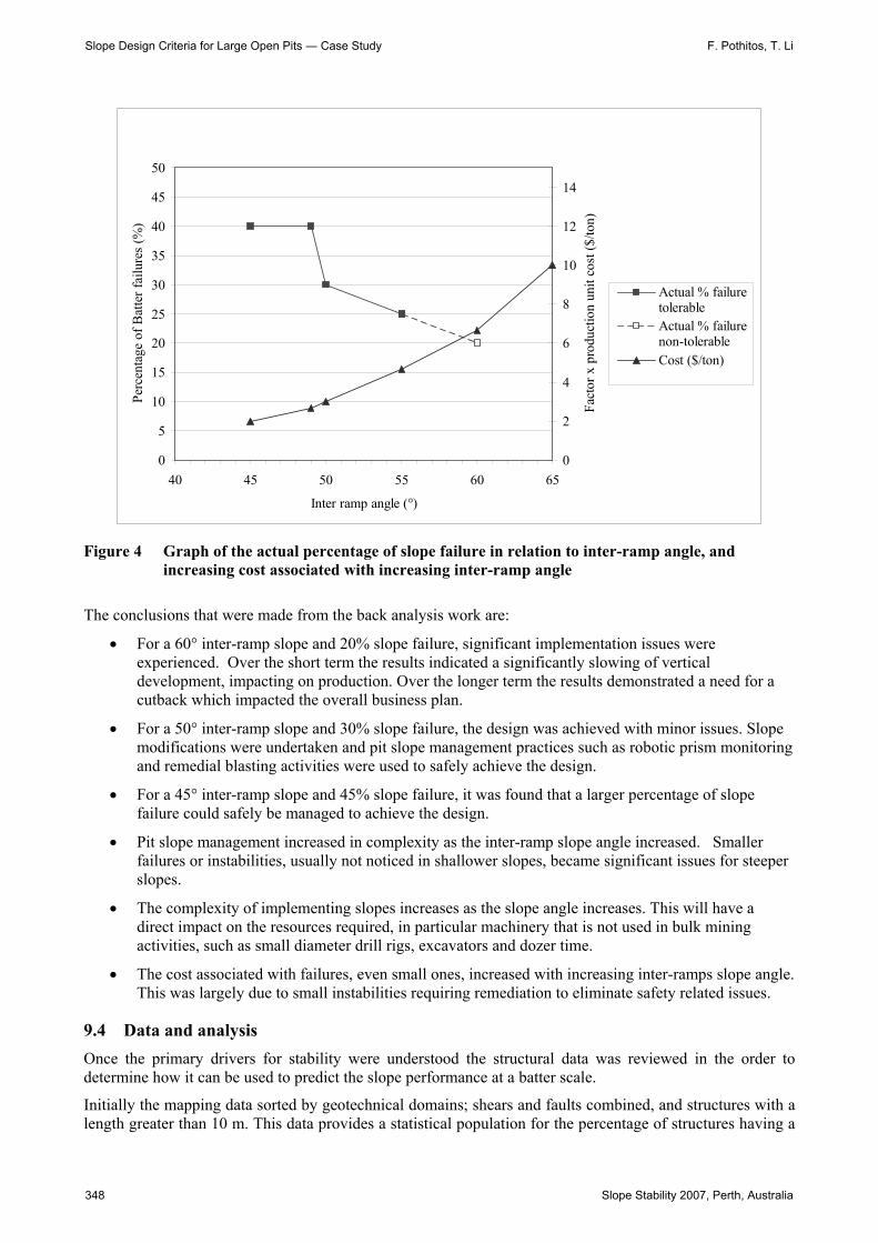
The data collected from back analysis was also graphed (Figure 4). The percentage of tolerable batter scale failure and non tolerable failure was plotted against inter-ramp angle. A line was drawn to link the points however a zone or window could be more representative. The line shows that there are decreasing failures with increasing slope angle which is in line with more competent material expected for the steeper slopes. The points graphed also show the tolerable and non-tolerable percentage of batter scale failures at varying inter-ramp slope angles.
Also graphed in Figure 4 is the cost of remedial activities. The line shows that the cost per unit ton of material remediated increases with increasing slope height. The reason for this is that as the slope angle increases the activities for remediation become more complex, e.g. cable bolting may be required for a relatively small block or a back filled ramp may be need to be established to drill and blast an unstable block.
Numerical Modelling of Rock Slope
Slope Stability 2007, Perth, Australia 347
0
5
10
15
20
25
30
35
40
45
50
40 45 50 55 60 65
Inter ramp angle (°)
Perc
enta
ge o
f Bat
ter f
ailu
res
(%)
0
2
4
6
8
10
12
14
Fact
or x
pro
duct
ion
unit
cost
($/to
n)
Actual % failuretolerableActual % failurenon-tolerableCost ($/ton)
Figure 4 Graph of the actual percentage of slope failure in relation to inter-ramp angle, and increasing cost associated with increasing inter-ramp angle
The conclusions that were made from the back analysis work are:
• For a 60° inter-ramp slope and 20% slope failure, significant implementation issues were experienced. Over the short term the results indicated a significantly slowing of vertical development, impacting on production. Over the longer term the results demonstrated a need for a cutback which impacted the overall business plan.
• For a 50° inter-ramp slope and 30% slope failure, the design was achieved with minor issues. Slope modifications were undertaken and pit slope management practices such as robotic prism monitoring and remedial blasting activities were used to safely achieve the design.
• For a 45° inter-ramp slope and 45% slope failure, it was found that a larger percentage of slope failure could safely be managed to achieve the design.
• Pit slope management increased in complexity as the inter-ramp slope angle increased. Smaller failures or instabilities, usually not noticed in shallower slopes, became significant issues for steeper slopes.
• The complexity of implementing slopes increases as the slope angle increases. This will have a direct impact on the resources required, in particular machinery that is not used in bulk mining activities, such as small diameter drill rigs, excavators and dozer time.
• The cost associated with failures, even small ones, increased with increasing inter-ramps slope angle. This was largely due to small instabilities requiring remediation to eliminate safety related issues.
9.4 Data and analysis Once the primary drivers for stability were understood the structural data was reviewed in the order to determine how it can be used to predict the slope performance at a batter scale.
Initially the mapping data sorted by geotechnical domains; shears and faults combined, and structures with a length greater than 10 m. This data provides a statistical population for the percentage of structures having a
Slope Design Criteria for Large Open Pits ― Case Study F. Pothitos, T. Li
348 Slope Stability 2007, Perth, Australia
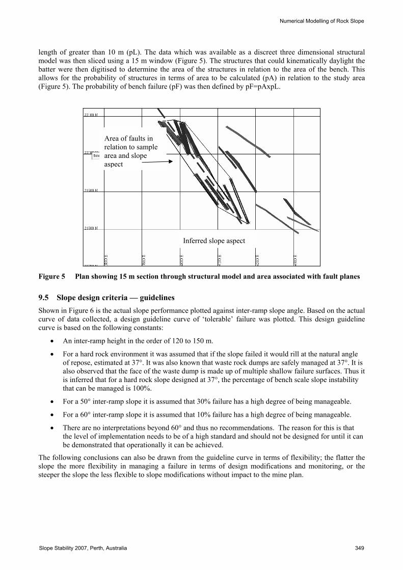
length of greater than 10 m (pL). The data which was available as a discreet three dimensional structural model was then sliced using a 15 m window (Figure 5). The structures that could kinematically daylight the batter were then digitised to determine the area of the structures in relation to the area of the bench. This allows for the probability of structures in terms of area to be calculated (pA) in relation to the study area (Figure 5). The probability of bench failure (pF) was then defined by pF=pAxpL.
Figure 5 Plan showing 15 m section through structural model and area associated with fault planes
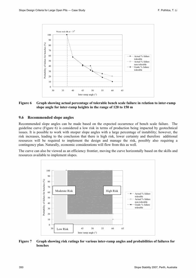
9.5 Slope design criteria — guidelines Shown in Figure 6 is the actual slope performance plotted against inter-ramp slope angle. Based on the actual curve of data collected, a design guideline curve of ‘tolerable’ failure was plotted. This design guideline curve is based on the following constants:
• An inter-ramp height in the order of 120 to 150 m.
• For a hard rock environment it was assumed that if the slope failed it would rill at the natural angle of repose, estimated at 37°. It was also known that waste rock dumps are safely managed at 37°. It is also observed that the face of the waste dump is made up of multiple shallow failure surfaces. Thus it is inferred that for a hard rock slope designed at 37°, the percentage of bench scale slope instability that can be managed is 100%.
• For a 50° inter-ramp slope it is assumed that 30% failure has a high degree of being manageable.
• For a 60° inter-ramp slope it is assumed that 10% failure has a high degree of being manageable.
• There are no interpretations beyond 60° and thus no recommendations. The reason for this is that the level of implementation needs to be of a high standard and should not be designed for until it can be demonstrated that operationally it can be achieved.
The following conclusions can also be drawn from the guideline curve in terms of flexibility; the flatter the slope the more flexibility in managing a failure in terms of design modifications and monitoring, or the steeper the slope the less flexible to slope modifications without impact to the mine plan.
Inferred slope aspect
Area of faults in relation to sample area and slope aspect
Numerical Modelling of Rock Slope
Slope Stability 2007, Perth, Australia 349
0
10
20
30
40
50
60
70
80
90
100
30 35 40 45 50 55 60 65
Inter ramp angle (°)
Prob
abili
ty o
f fai
lure
for b
ench
es (%
)
Actual % failuretolerableActual % failurenon-tolerableGuide % failuretolerable
Waste rock rills at ~ 370
Figure 6 Graph showing actual percentage of tolerable bench scale failure in relation to inter-ramp slope angle for inter-ramp heights in the range of 120 to 150 m
9.6 Recommended slope angles Recommended slope angles can be made based on the expected occurrence of bench scale failure. The guideline curve (Figure 6) is considered a low risk in terms of production being impacted by geotechnical issues. It is possible to work with steeper slope angles with a large percentage of instability; however, the risk increases, leading to the conclusion that there is high risk, lower certainty and therefore additional resources will be required to implement the design and manage the risk, possibly also requiring a contingency plan. Naturally, economic considerations will flow from this as well.
The curve can also be viewed as an efficiency frontier, moving the curve horizontally based on the skills and resources available to implement slopes.
0
10
20
30
40
50
60
70
80
90
100
30 35 40 45 50 55 60 65
Inter ramp angle (°)
Prob
abili
ty o
f fai
lure
for b
ench
es (%
)
Actual % failuretolerableActual % failurenon-tolerableGuide % failuretolerable
Figure 7 Graph showing risk ratings for various inter-ramp angles and probabilities of failures for benches
Moderate Risk High Risk
Low Risk
Slope Design Criteria for Large Open Pits ― Case Study F. Pothitos, T. Li
350 Slope Stability 2007, Perth, Australia
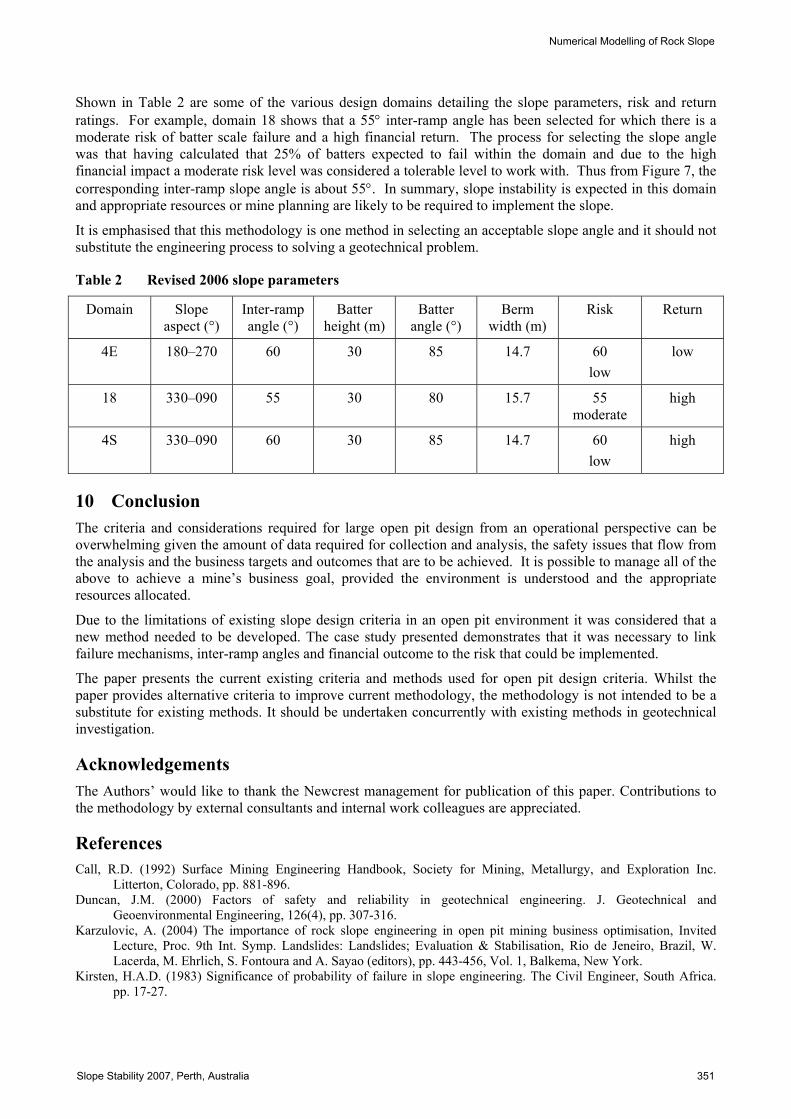
Shown in Table 2 are some of the various design domains detailing the slope parameters, risk and return ratings. For example, domain 18 shows that a 55° inter-ramp angle has been selected for which there is a moderate risk of batter scale failure and a high financial return. The process for selecting the slope angle was that having calculated that 25% of batters expected to fail within the domain and due to the high financial impact a moderate risk level was considered a tolerable level to work with. Thus from Figure 7, the corresponding inter-ramp slope angle is about 55°. In summary, slope instability is expected in this domain and appropriate resources or mine planning are likely to be required to implement the slope.
It is emphasised that this methodology is one method in selecting an acceptable slope angle and it should not substitute the engineering process to solving a geotechnical problem.
Table 2 Revised 2006 slope parameters
Domain Slope aspect (°)
Inter-ramp angle (°)
Batter height (m)
Batter angle (°)
Berm width (m)
Risk Return
4E 180–270 60 30 85 14.7 60 low
low
18 330–090 55 30 80 15.7 55 moderate
high
4S 330–090 60 30 85 14.7 60 low
high
10 Conclusion The criteria and considerations required for large open pit design from an operational perspective can be overwhelming given the amount of data required for collection and analysis, the safety issues that flow from the analysis and the business targets and outcomes that are to be achieved. It is possible to manage all of the above to achieve a mine’s business goal, provided the environment is understood and the appropriate resources allocated.
Due to the limitations of existing slope design criteria in an open pit environment it was considered that a new method needed to be developed. The case study presented demonstrates that it was necessary to link failure mechanisms, inter-ramp angles and financial outcome to the risk that could be implemented.
The paper presents the current existing criteria and methods used for open pit design criteria. Whilst the paper provides alternative criteria to improve current methodology, the methodology is not intended to be a substitute for existing methods. It should be undertaken concurrently with existing methods in geotechnical investigation.
Acknowledgements The Authors’ would like to thank the Newcrest management for publication of this paper. Contributions to the methodology by external consultants and internal work colleagues are appreciated.
References Call, R.D. (1992) Surface Mining Engineering Handbook, Society for Mining, Metallurgy, and Exploration Inc.
Litterton, Colorado, pp. 881-896. Duncan, J.M. (2000) Factors of safety and reliability in geotechnical engineering. J. Geotechnical and
Geoenvironmental Engineering, 126(4), pp. 307-316. Karzulovic, A. (2004) The importance of rock slope engineering in open pit mining business optimisation, Invited
Lecture, Proc. 9th Int. Symp. Landslides: Landslides; Evaluation & Stabilisation, Rio de Jeneiro, Brazil, W. Lacerda, M. Ehrlich, S. Fontoura and A. Sayao (editors), pp. 443-456, Vol. 1, Balkema, New York.
Kirsten, H.A.D. (1983) Significance of probability of failure in slope engineering. The Civil Engineer, South Africa. pp. 17-27.
Numerical Modelling of Rock Slope
Slope Stability 2007, Perth, Australia 351

Li, T., Pothitos, F. and Hewson, S. (2003) Design and optimisation of Cadia Hill Open Pit, Cadia Valley Operations, Newcrest Mining Limited. Proc. 5th Large Open Pit Conference, The Australian Institute of Mining and Metallurgy, Melbourne, pp. 123-126.
McCracken, A. and Jones, G.A. (1986) Use of probabilistic stability analysis and cautious blast design for an urban excavation, Rock Engineering and Excavation in and Urban Environment, The Institute of Mining and Metallurgy, Hongkong.
Pine, R.J. (1992) Risk analysis design application in mining geomechanics, Transactions of Institute of Mining and Metallurgy, (Section A: Mining Industry), pp. A149-A158.
Pothitos, F., Clark, D., Li, T. and Hewson, S. (2003) Slope stability major hazard management plan and operating procedures at Cadia Hill Open Pit, Cadia Valley Operations, Newcrest Mining Limited. Proc. 5th Large Open Pit Conference, Kalgoorlie, November 3-5, 2003.
Pothitos, F., Webster, S., Meagher, L. and Li, T. (2006) Cadia Extended Pit instability monitoring and management. Proc. 2nd Int Seminar on Strategic versus Tactical Approaches in Mining, March 2006, Perth.
Priest, S.D. and Brown, E.T. (1983) Probabilistic stability analysis of variable rock slopes, Transactions of Institute of Mining and Metallurgy, (Section A: Mining Industry), 1983, pp. A1-A12.
Sjoberg, J. (1999) Analysis of Large Scale Rock Slopes, PhD Thesis, Lulea University of Technology, Lulea. Sullivan, T.D. (1994) Mine Slope Design, The Chances of Getting the Answer Right and The Risk of Getting it Wrong.
Proceedings Fourth Large Open Pit Mining Conference, Perth, 5-9 September 1994. U.S. Army Corps of Engineers (1998) Risk-based analysis in geotechnical engineering for support of planning studies.
Engrg. Circular No. 1110-2-554, Department of the Army, Washington, D.C., www.usace.army.mil/usace-docs&, 27 February 1998.
Slope Design Criteria for Large Open Pits ― Case Study F. Pothitos, T. Li
352 Slope Stability 2007, Perth, Australia