slatyfork sawmill interior - republic locomotive works sawmill interior #28301 n scale remove the...
TRANSCRIPT

HistoryEmpty sawmills are lonely places. This kit includes all themachinery and basic details needed to deck out the SlatyforkSawmill main floor and sawfiler's area.
Instructions
Read the instructions completely and study the photos anddrawings before starting construction!
Warranty
All R.L.W. products are guaranteed against defects inmanufacturing and will be replaced or repaired asdetermined by R.L.W. after inspection of the part. ContactR.L.W for a return authorization prior to returning anydamaged parts. R.L.W will also replace parts that aredamaged during assembly. This part of the warranty isvoided if the kit has been modified in any way.
Drop Outs
The laser-cut sheets may look like pieces are missing, butthese holes are intentional. These waste pieces, called dropouts, may still be clinging to the sheet and fall out whentouched. Save them for use as clutter and scraps when doingthe final detailing.
McCabe Lumber Co.
Slatyfork Sawmill Interior#28301 N Scale
Remove the pieces from the carrier sheets with a sharphobby knife as they are needed, and lightly sand off theremainder of the tabs. On the thicker pieces there is a slightdraft angle caused by the laser. This angle can be removedwith a pass or two of a fine sanding block.
Identify all the parts, checking them against the parts list. Mostwood parts have a number either on them or nearby. Extrasmall parts may be included. Do not remove the parts from thecarrier yet!
Repetitive Steps
Every different procedure or method is discussed in detailin the instructions; however, once it has been discussed, itis not repeated in detail again.
Dimensions and Directions
All dimensions specified in the text are actual feet and inchesunless used with the word “scale” before or after them.
Atmospheric Conditions
Wood and paper products are effectively live materials onwhich humidity and temperature changes will change thesize of parts slightly.
R.L.W.R.L.W.R.L.W.R.L.W.R.L.W.
McCabe Lumber Company
2
End User Information
This kit is not intended for use by novice modelers, orindividuals under the age of 18 without the supervision ofan adult. Additionally, the modeler assumes all liabilityregarding the proper use of this product or any productsuggested. The user must become familiar with the kitinstructions, and instructions on any product used tocomplete this kit. Please read and follow all safetyprocedures for all products used to finish this kit. Detailsmay vary between scales and from the sample model shown.
Color PalletThe basic colors are from the Floquil railroad colors lineexcept as noted. You may follow our suggested pallet:
Coach Green Stainless SteelRust Reefer GrayRail Tie Brown Caboose RedAged Concrete Antique WhiteEarth Grimy BlackWoodland Scenics' Mini-Scene Paint Set
Naturally, you may use any colors you wish. Justremember that flat, dull colors are preferable to loud brightcolors for a realistically-finished model. Some colorsapparent in the photos are mixtures of two or more of thebasic colors. These mixtures are used only on detail itemsand are not critical.
On the model, Coach Green was used on the machinery.The blades, rollers and outer surfaces of the wheels werepainted Stainless Steel. Reefer Gray was used on the woodcomponents. Control levers are painted Caboose Red withGrimy Black handles. Most parts can be painted prior to assembly and mostshould be painted prior to removing from the carrier sheet.Since excess paint can cause warping, use small amountsand paint both sides. In addition, the parts should beairbrushed lightly with the base color rather than paintedwith a brush; this will reduce the opportunity for it to warpout of shape. A light base coat can be applied using a spraycan if an airbrush is not available. Placing under a flat weightwill also reduce warping.
Please, wear rubber gloves and a paint mask whendealing with model paints, and work in a well-vented area.Some of the solvents are not user-friendly!
Wood Grain and ColorWood grain is just one of several items that is well worththe time necessary to apply it and gives a proper look andfeel to a wood structure. It will look better if the wood graingoes on after the initial base color coat. The addition ofwood grain will also make the nail holes on a given wallless prominent. Please remember that wood grain should
only be applied to parts representing wood on the finishedmodel.
1. Use a sharp hobby knife to apply the wood grain.
2. Add two to three lines of wood grain per laser-cut boardor laser-scored board. Do this by beginning at the end of ascale board and working to the other end in one continuousline. Do not try to make these lines straight, but rather justtry to stay on that board. Slight waviness is exactly the resultyou will want.
3. Trim the ends of some boards shorter than others andcarve away some of the material between boards.
A base coloration of thinned light tan, such as Earth, is usedfor all of the wooden components in this kit not specified tobe a specific color. Some folks think it is necessary to sandthe black edges off of all of the laser-cut parts. Not true. Ifyou follow the suggested painting techniques, you will nothave to spend time sanding all the edges of parts beforeassembly. Laser-cut edges can be base-colored with AntiqueWhite prior to applying a light color. This will easily hideany burned edges.
WeatheringThe gray weathering wash formula used is based onexperience with laser-cut components and castings, andshould be applied after all the paint work is done. Too darka formula of weathering stain against a relatively-light finishcoat will tend to overemphasize laser-engraved nail holes.You may wish to try this weathering wash formula:
• Obtain a one ounce empty bottle. • Fill your bottle about 3/4 full with denatured alcohol. • Add about 30 drops of India ink and mix well.
This Alcohol & India Ink (A&I) wash will be used on thedetails of this kit. If it needs to be slightly darkened, justadd more ink. However, it is a good practice to re-wash anobject rather than use a wash which might be too dark. Thiswash should be used on all of the castings after paintingthem, and after final placement to mute the colorsrealistically. When first applied, it will look terrible, but letit dry before passing final judgement.
The second wash is a reddish-brown mixture. Usingthe same procedure listed above, simply substitute brownshoe dye for the India ink to create an Alcohol & Dye (A&D)wash. It can be used on all castings also.
An alternate method for final weathering is to usepowdered chalks. You will also need a 1” wide soft brush.Never use this brush for anything other than chalk work.And never wash this brush! Use your brush to dust allexterior surfaces of the model. Brush and blow off excess
3
RLWRLWRLWRLWRLWchalk. Practice on scraps prior to dusting the model. Theproper effect will dust the model slightly and will enhancethe details of the model.
CastingsThe castings in our kits are made most often of metal.However, they may also be injection-molded styrene or cold-cast urethane. These latter two types of parts must be washedwith warm soapy water instead of lacquer thinner. It is alsovery important to thoroughly rinse them after washing them.Urethane parts may be sanded and filed easily, but the dustshould not be inhaled! Paint all styrene parts with Barrierbefore painting them with other Floquil paints. Urethaneparts may be directly painted with Floquil paints. Severalalloys are used to produce metal parts for our kits. All themetal parts should be handled with care as denting andbreakage may occur if they are dropped.
WARNING: The metal castings in this kit may containvery minute levels of lead. Most of the castings in this kitare now 99.5% or more lead free. But to be on the safe side,keep all parts away from pets and small children, don’t lickyour fingers while building this kit, and always wash yourhands after handling the castings!.
Cleaning the metal castings is quite easy. Severaljewelers’ files and a sharp hobby knife work well for thisprocedure. After you have completed the initial cleanup ofparting lines, sprues and flash, wash all the castings inlacquer thinner, or denatured alcohol, and allow them todry. Handle these after washing by wearing gloves to avoidgetting them contaminated with the oils from your hands.
Sometimes the metal castings in the scene were treatedwith Blacken-It according to the product instructions. Thechemical reaction between the Blacken-It and the metalcreates a very realistic weathered-metal finish. Additionally,all metal castings can be treated in this manner to providegreater paint adhesion.
Painting the castings is quite easy and can beaccomplished with a brush or airbrush. A good base coatwill be created by airbrushing your castings with FloquilEarth or light gray paint. Krylon gray primer in a spray canworks well as an alternative to an airbrush. Choose relativelydull colors for your castings. Models tend to look morerealistic using shades such as Mud, Grimy Black, etc. byFloquil, or similar dull shades. Rarely should you considerusing bright colors in model scenes. The Woodland Scenicswater-base colors work well for this.
Tools Required for AssemblyTools required for this kit: Hobby knife and sharp blades(we buy surgical blades from the pharmacy - very sharp
and extremely thin), sanding block/emery boards, metalstraight edge/hobby scale, glues (ACC, Titebond woodcement, Elmers White Glue, JB Weld Epoxy), paints/stains,assorted twist drills and pin vise.
SandingIt has been said that sanding is not necessary on a laser-cutkit. This is not true! Proper sanding makes the differencebetween a kit simply assembled and one that shows the touchof a true master craftsman. While the laser can cut precisely,the amount and types of glue used in assembly can alter thefit. Dressing the edges with a quick pass of the sandpaperwill greatly improve the appearance of the finished model.Always keep an assortment of sand papers and emery boardsin your tool box. Grits ranging from 200 to 600 will behelpful. Just about all exposed joints need to be dressedwith fine sandpaper like 600-grit. This will greatly improvethe appearance of the model.
PhotosIn some of the assembly photos, the parts have not beenpainted. This was intentional to help show off the differentpieces easier. In most cases, the photos show the O scalemodel that has slightly different details from the HO scaleversion. This will not affect the assembly of the kit. Andsome photos may show parts assembled slightly out of therecommended order.
GluingTitebond, a brand name of strong wood glue, is used toassemble the large components in this kit. The residue fromthis glue will have a yellow tint, so be sure to clean up anyexcess. White glue is used to attach the smaller parts as thisglue will dry clear. When applying glue to the smaller parts,it is best to use a toothpick to apply a thin layer of glue tothe back of the parts and then press them in place on thestructure. Any excess glue can be wiped off with a dampcotton swab.
Extra PartsWith some small parts, extras are included just in case.
Strange Terms and AcronymsN-B-W is a Nut-Bolt-Washer Casting. They are usuallymade of plastic.ACC is alphacyanoacrylate glue, i.e., superglue.Sprue - The passage through which molten material isintroduced into a mold. During casting or molding, thematerial in the sprue will solidify and needs to be removedfrom the finished part.

McCabe Lumber Company
4
The main machinery components - band saws,edgers, log carriages and tracks, and swing saws- are packaged in plastic bags to help keep thingssimple. Do not open these until it is time to buildand install them. Note: The specific parts listfor each of these pieces of machinery isincluded in the specific section of theseinstructions. The parts list in the back of theinstructions is for the remainder of the kit.
The floor of the sawmill may be already installedin the mill, but this will not be a big problem.Since the mill was designed prior to creating this interior kit, there need to be six holes added to the samill floor.Position the cardstock template on the right side of the mill as shown below - looking at the mill from the front- with the front of the template flush with the front corner of the floor and the laser-engraved text facing up.Mark the holes for the edgers and ends of the log carriage track, and the triangular position marks for the endsof the log carriage track. Remove the template, flip it over so the laser-engraved text is now facing down towardthe floor, and position it on the left side of the mill. Again, mark the two holes and the triangular position marksfor the ends of the log carriage track; ignore the holes for the edgers at this time.
Using a #60 drill, drill the inside of the corners of the six holesonly - not the triangle marks - and with a hobby knife,remove the material from the holes.
There are already two large holes in the floorfor the bandsaws. The bandsaws andthe transfer will be the keycomponents for positioningthe remainder of theparts and should beinstalled first.
Front of Mill
5
RLWRLWRLWRLWRLWTransfer
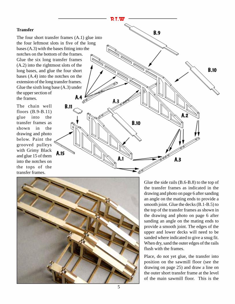
The four short transfer frames (A.1) glue intothe four leftmost slots in five of the longbases (A.3) with the bases fitting into thenotches on the bottom of the frames.Glue the six long transfer frames(A.2) into the rightmost slots of thelong bases, and glue the four shortbases (A.4) into the notches on theextension of the long transfer frames.Glue the sixth long base (A.3) underthe upper section ofthe frames.
The chain wellfloors (B.9-B.11)glue into thetransfer frames asshown in thedrawing and photobelow. Paint thegrooved pulleyswith Grimy Blackand glue 15 of theminto the notches onthe tops of thetransfer frames.
Glue the side rails (B.6-B.8) to the top ofthe transfer frames as indicated in thedrawing and photo on page 6 after sandingan angle on the mating ends to provide asmooth joint. Glue the decks (B.1-B.5) tothe top of the transfer frames as shown inthe drawing and photo on page 6 aftersanding an angle on the mating ends toprovide a smooth joint. The edges of theupper and lower decks will need to besanded where indicated to give a snug fit.When dry, sand the outer edges of the railsflush with the frames.
Place, do not yet glue, the transfer intoposition on the sawmill floor (see thedrawing on page 25) and draw a line onthe outer short transfer frame at the levelof the main sawmill floor. This is the
McCabe Lumber Company
6
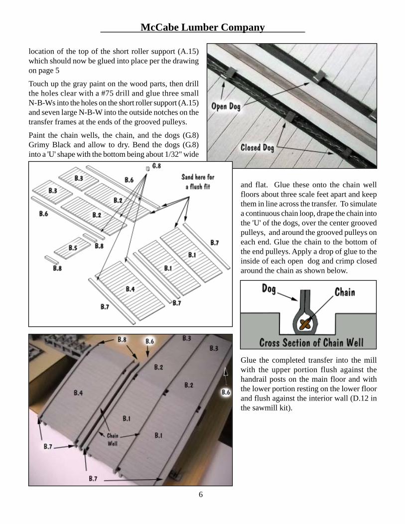
location of the top of the short roller support (A.15)which should now be glued into place per the drawingon page 5
Touch up the gray paint on the wood parts, then drillthe holes clear with a #75 drill and glue three smallN-B-Ws into the holes on the short roller support (A.15)and seven large N-B-W into the outside notches on thetransfer frames at the ends of the grooved pulleys.
Paint the chain wells, the chain, and the dogs (G.8)Grimy Black and allow to dry. Bend the dogs (G.8)into a 'U' shape with the bottom being about 1/32" wide
and flat. Glue these onto the chain wellfloors about three scale feet apart and keepthem in line across the transfer. To simulatea continuous chain loop, drape the chain intothe 'U' of the dogs, over the center groovedpulleys, and around the grooved pulleys oneach end. Glue the chain to the bottom ofthe end pulleys. Apply a drop of glue to theinside of each open dog and crimp closedaround the chain as shown below.
Glue the completed transfer into the millwith the upper portion flush against thehandrail posts on the main floor and withthe lower portion resting on the lower floorand flush against the interior wall (D.12 inthe sawmill kit).

7
RLWRLWRLWRLWRLWLog Carriages and Tracks
The carriage frame is assembled from the two sides(A.1) and the two ends (A.2). Glue the center beams(A.3) into place.
Glue the end sheets (D.1) over the carriage ends (A.2)with the bottoms flush. Glue the wheel spacers (D.2)over the axle holes on the sides of the carriage.
Glue the carriage deck pieces (B.1-B.3) in placecentered on the carriage frame between thenotched areas. The seat base (C.7) glues into thescribed area at the back of the carriage. Drill thetwo holes clear with a #75 drill and glue a N-B-Winto each hole. Add the seat by gluing the back(B.4) onto the seat base flush with the back of thebase. Glue the sides (B.5) to the base and back,then glue the seat (B.6) onto the sides.
Glue the three headblocks to the notched areas ontop of the carriage frame. There should be a scalefoot overhang on the front side of the carriage -that is the side facing the saw.Drill the axle holes clear with a #72 drill and drill theremaining 14 holes in the carriage sides and ends clearwith a #78 drill. Glue a N-B-W into the four holes on eachside and the three holes across the top of the end sheets.Touchup the paint.Trim the axles on the back of the wheels to a length of fivescale inches. Glue the wheel axle into the hole of the wheelspacer with the wheel flush against the spacer. Cut sixlengths of 0.015 wire to a scale 3'-4" length and insert intothe axle holes on the inside of the frame to represent theaxles.
Where the carriage is placed on the track determines thelength of the brown line; cut it to give two lengths that willrun from the end sheets of the carriage over the rollers atthe end of the track and into the floor. Glue the brown lineinto the bottom hole of the end sheet on each end of thecarriage. The other ends will later be glued over the rollerand under the floor at the end of the track.

McCabe Lumber Company
8
Log Carriage and Track Parts(Quantity per Bag - Two Bags per Kit)
QTY MATERIALSet Works 1Headblock 3Roller 4Nut-Bolt-Washer 16Wheel 12Rail 4Spikes 40
Wire, 0.015" 21
Brown Line 1
A.1 Carriage Side 2 1/32PlyA.2 Carriage End 2 1/32PlyA.3 Carriage Center Beam 2 1/32Ply
B.1 Deck, End 2 1/32PlyB.2 Deck, Center, Left 1 1/32PlyB.3 Deck, Center, Right 1 1/32PlyB.4 Seat Back 1 1/32PlyB.5 Seat Side 2 1/32PlyB.6 Seat 1 1/32Ply
C.1 Tie Strip, Left 1 1/16 BassC.2 Tie Strip, Right 1 1/16 BassC.3 Not UsedC.4 Roller Support 8 1/32PlyC.5 Rail Base, End 4 1/32PlyC.6 Rail Base, Center 2 1/32PlyC.7 Seat Base 1 1/32Ply
D.1 End Sheet 2 White CardD.2 Wheel Spacer 12 White Card
Back View
Drill the holes in the eight roller supports (C.4) clear with a #78 drill and glue them to the tie strips (C.1,C.2) where marked as shown in the drawing on page 5. The rollers drop in place between thesupports and a small length of 0.015 wire is inserted from the side of the support to hold the roller inplace.The two tie strips (C.1, C.2) glue together as shown in the drawing. Glue rail bases(C.5, C.6) to the top of the tie strip with the scribed holes on top and the outsideedges inset two scale inches from the end of the ties.Trim the rails to length and file the ends smooth. Glue them in placecentered on the rail bases with ACC, then when dry, spike atthe places indicated by the scribed holes. It will be easierto spike if the scribed holes are pre-drilled clearwith a #79 drill.Glue the rail base to the floor. Gluethe carriage to the rails. Wrap thecord over the end rollers andglue it in place with the tail ofthe cord sticking into the holein the floor.

9
RLWRLWRLWRLWRLWLeft and Right Band Saws
This model was inspired by one from the Cordesman Machine Co. Thissaw did all the hard work of cutting the logs into cants.
The band saw has been assembled and painted a base coat of green byour friends in the orient. The rollers and outer surface of the wheelsshould be painted silver. The control handle and adjustment wheel canbe painted black or red.
Warning! The saw blade is sharp and can cut you! No bandagesare included with this kit!
On the right band saw, position the blade so that the teeth are pointingdownward through the slot next to the roller and facing the bandsaw frame. On the left band saw, position the blade so that theteeth are pointing downward through the slot next to the roller andfacing away from the band saw frame as shown in the photos.
Gently bend the center of the bandsaw blade to match the radius ofthe top saw wheel and shape the rest of the blade to fit the saw.Once the blade passes through the floor it is not visible, so there isno need to shape the bottom of the blade correctly; however, it canbe done and glued in place as shown in the photos. ACC the bladein place after sliding the saw blade into the slot shown.
Glue the two bases of each saw together with the scribed lines ofthe base on top and the holes lined up. Paint as desired.
Once the saw is glued in place on the base, the floor plate glues intoposition around the back of the band saw to cover the large openingsin the base. Two handles are bent from the 0.010" wire and glued intothe holes in the access hatches on the floor plate.
Glue the bases, left and right to the sawmill main floor with the teeth ofthe blades pointing toward the jackslip end of the mill and the roller sideof the band saw close to the log carriage track.
Warning! The saw blade is sharp and can cut you!
QTY MATERIAL
Band Saw 1Blade 1
Wire, 0.010" 1
Base 1 1/16 Bass
Sub-Base 1 1/16 Bass
Floor Plate 1 White Card
Band Saw Parts(Quantity per Bag - Two Bags per Kit)
Left Band Saw

McCabe Lumber Company
10
Left Band Saw
Edgers
The edger, or resaw, is based upon one from the CorinthManufacturing Co. model. Its job is to rip cut the cantsinto individual boards. Adjustable round blades are inthis saw and the operator moves them as needed toproduce various width boards.
The edger has been assembled and painted a base coat ofgreen by our friends in the orient. The rollers and outersurface of the wheels should be painted Stainless Steel.
A piece of 0.010" wire is used to formthe shaft that holds the blades. Cut itto fit into the dimple on the middlewheel of the three-wheel side of theedger frame with the other end restingon the ledge on the single-wheel sidedirectly behind the wheel's axle.
Glue a blade hub (B.2) to each sideof the blades (B.1) centered over the hole. Slide as manyblades as desired on to the brass wire, position them spacedevenly, and glue in place. Paint this assembly StainlessSteel and glue in place in the edger frame.
The sheet with the various widths of bond paper stripsshould be painted with Floquil Rail Brown to be usedfor the belts. Choose a width close to the size of thewheels. On the side with three drive wheels, loop thebelt around the three and glue the joint at the bottom ofthe center wheel. On the other side, a belt runs over thetop of the drive wheel and into the floor. Glue the edgersto the floor with this belt in the hole and the corners ofthe edger frames inside the corner marks on the mainsawmill floor.
With the scribed lines on the outside, the roller frames(A.1, A.2) connect together with the bottom (A.4) andtop (A.3) braces. Keep the frame assembly square and

11
RLWRLWRLWRLWRLW
Edger Parts(Quantity per Bag - Two Bags per Kit)
QTY MATERIAL
Edger 1Roller, 4' 15
Wire, 0.010" 1
A.1 Roller Side, Long 2 1/32PlyA.2 Roller Side, Short 2 1/32PlyA.3 Roller Top Brace 6 1/32PlyA.4 Roller Bottom Brace 6 1/32Ply
B.1 Blade 6 White CardB.2 Blade Hub 12 White Card
Belt 2 Bond Paper
sand the edges smooth when dry.
Paint the roller castings before gluing into place; the rollercan be silver and the pillow blocks on each end can bepainted green. The roller castings glue to the tops of theframes with one positioned at each end and the rest spacedapproximately a scale 24" apart between them.
Glue the roller frames to the floor on each side of the edgeras shown with the long roller spaced approximately 24scale inches from the sloped front of the edger frame andthe rear roller approximately nine scale inches behind theframe. The edge of the roller frames on the large wheelside of the edger will be in line with the edger frame asshown in the photo at the right.

McCabe Lumber Company
12
Left and Right Swing Saws
The swing saw, a R. R. Howell Co. product, is manuallyoperated and is used to trim the length of the boards.Waste falls below the rollers eventually going into theslash burner or the fireboxes of the boilers.
With the scribed lines on the outside, the roller sides(A.1) connect together with the bottom (A.3) and top(A.2) braces. Keep the frame assembly square and sandthe edges smooth when dry.
Determine which end of the roller assembly will havethe saw frame. The photos show it on the left so thiswill be the saw on the left side of the mill; to put it onthe right simply rotate the frame (B.1) 180 degreesbefore assembly and glue it to the other end of the rolleras shown in the Right Side drawing.
Left Side Right Side
Glue the frame top (B.2) to the frame (B.1). Thediagonal braces (B.3) glue between the frame and theframe top. Sand all the edges smooth when the gluehas dried.
Glue the frame top boards (C.5) to the outside edgesand the saw hanger top boards (C.4) to the frame topas shown in the drawing. Keep the holes in the sawhanger top boards in line with the holes in the frametop.
Glue the bottom joist (C.1) to the back of the frameflush with the bottom of the frame. Glue the top joist(C.2) to the top of the frame with the top edge of thejoist flush with the top of the top boards. Add thediagonal brace (C.3) to the back of the frame keeping
13
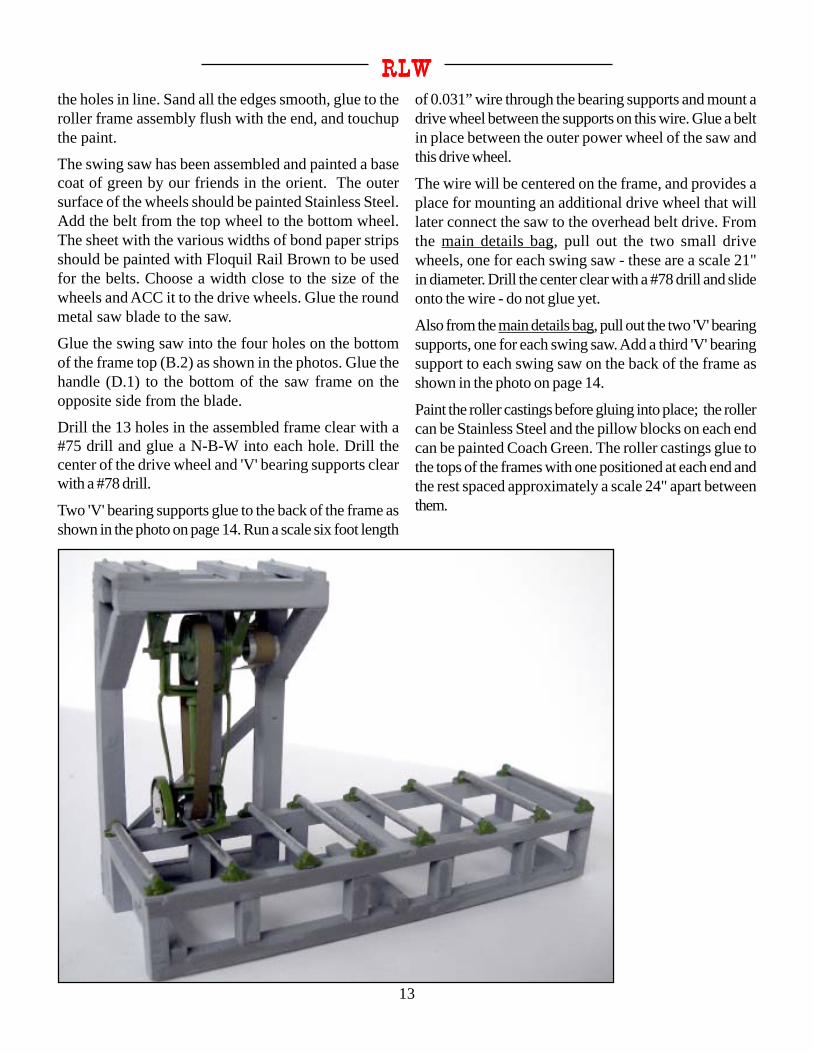
RLWRLWRLWRLWRLWthe holes in line. Sand all the edges smooth, glue to theroller frame assembly flush with the end, and touchupthe paint.
The swing saw has been assembled and painted a basecoat of green by our friends in the orient. The outersurface of the wheels should be painted Stainless Steel.Add the belt from the top wheel to the bottom wheel.The sheet with the various widths of bond paper stripsshould be painted with Floquil Rail Brown to be usedfor the belts. Choose a width close to the size of thewheels and ACC it to the drive wheels. Glue the roundmetal saw blade to the saw.
Glue the swing saw into the four holes on the bottomof the frame top (B.2) as shown in the photos. Glue thehandle (D.1) to the bottom of the saw frame on theopposite side from the blade.
Drill the 13 holes in the assembled frame clear with a#75 drill and glue a N-B-W into each hole. Drill thecenter of the drive wheel and 'V' bearing supports clearwith a #78 drill.
Two 'V' bearing supports glue to the back of the frame asshown in the photo on page 14. Run a scale six foot length
of 0.031” wire through the bearing supports and mount adrive wheel between the supports on this wire. Glue a beltin place between the outer power wheel of the saw andthis drive wheel.
The wire will be centered on the frame, and provides aplace for mounting an additional drive wheel that willlater connect the saw to the overhead belt drive. Fromthe main details bag, pull out the two small drivewheels, one for each swing saw - these are a scale 21"in diameter. Drill the center clear with a #78 drill and slideonto the wire - do not glue yet.
Also from the main details bag, pull out the two 'V' bearingsupports, one for each swing saw. Add a third 'V' bearingsupport to each swing saw on the back of the frame asshown in the photo on page 14.
Paint the roller castings before gluing into place; the rollercan be Stainless Steel and the pillow blocks on each endcan be painted Coach Green. The roller castings glue tothe tops of the frames with one positioned at each end andthe rest spaced approximately a scale 24" apart betweenthem.

McCabe Lumber Company
14
Swing Saw Parts(Quantity per Bag - Two Bags per Kit)
QTY MATERIAL
Swing Saw 1Blade 1Roller, 4' 8Nut-Bolt-Washer 13Drive Wheel 1'V' Bearing Support 2Wire, 0.015" 1
A.1 Roller Side 2 1/32PlyA.2 Roller Top Brace 3 1/32PlyA.3 Roller Bottom Brace 3 1/32Ply
B.1 Frame 1 1/16BassB.2 Frame Top 1 1/16BassB.3 Frame Diagonal Brace 2 1/16BassC.1 Bottom Joist 1 1/64 PlyC.2 Top Joist 1 1/64 PlyC.3 Back Brace 1 1/64 PlyC.4 Saw Hanger Top Board 2 1/64 PlyC.5 Frame Top Board 2 1/64 PlyD.1 Handle 1 1/64 Ply
Belt 2 Bond Paper
Build the six hog chutes* by bending the chutes (K.1) asshown in the drawing. Glue the hog chute base (J.1) to theinside bottom of the chute, then glue the four sides of thehog chute together. Paint the outside Reefer Gray with aBlack interior. One chutewill glue under each swingsaw inside the roller frame.The other four hog chuteswill be used later.
The swing saws are placedon the main sawmill floorinline with the back rollerof the edgers; the frontedge of the swing sawsshould be close to theshort edger roller. Doublecheck the location usingthe overhead belt framethat is discussed on page 17. The center drive wheels thatwill be on the overhead belt frame should line up over thesmall drive wheel on the back of the swing saw. The topphoto on page 12 shows the swing saw at the right. Markthe location for the hog chute and glue it and the swing sawin place, one on the left and one on the right.
Back
* - The hog chutes direct scrap pieces of wood down to the hog that is on the first floor of the mill. The hogis a grinder that makes chips of the wood before sending them to the slash burner.

15
RLWRLWRLWRLWRLWRollers
There are three long rollers and one shortroller in the kit. With the scribed lineson the outside, the roller sides (A.11,A.12) connect together with the bottom(A.14) and top (A.13) braces. Keep theframe assembly square and sand the edgessmooth when dry.Paint the roller castings before gluing intoplace; the roller can be silver and thepillow blocks on each end can be paintedgreen. The roller castings glue to the topsof the frames with one positioned at eachend and the rest spaced approximately ascale 24" apart between them.
The rollers are positioned 20 scale inchesaway from the log carriage track. Theshort roller will rest on the roller supportthat has been attached to the transfer.Check the layout on pages 25 and 26.
Hog Chutes
Glue two previously assembled hog chutes near the end of the shortedger rollers next to the swing saws. The other two hog chutes canbe placed as desired; there is no specific location for these.
McCabe Lumber Company
16
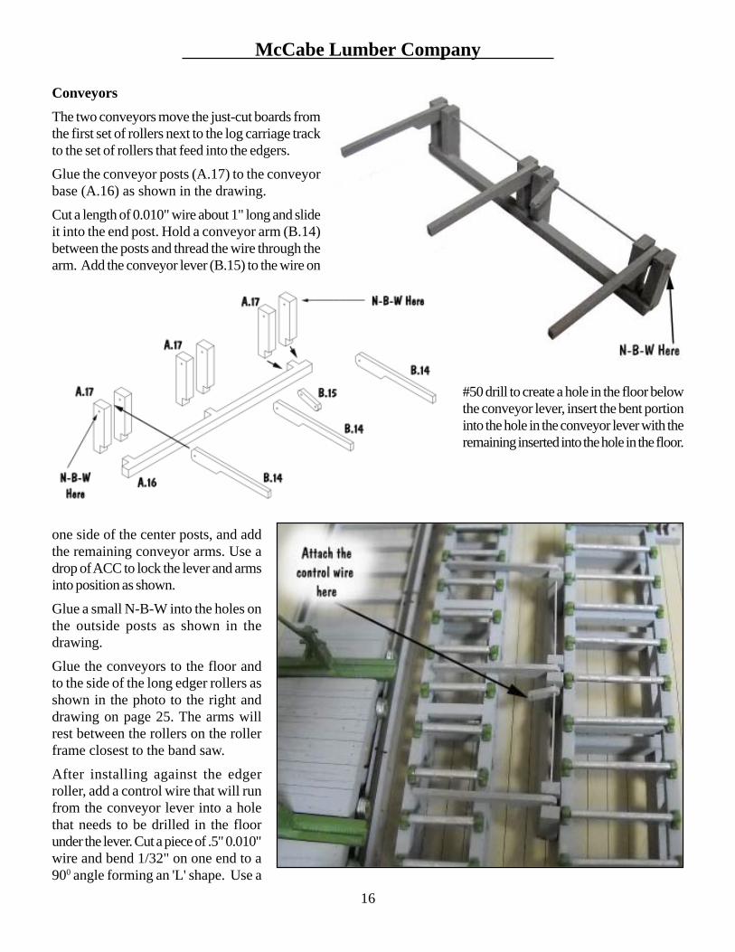
Conveyors
The two conveyors move the just-cut boards fromthe first set of rollers next to the log carriage trackto the set of rollers that feed into the edgers.Glue the conveyor posts (A.17) to the conveyorbase (A.16) as shown in the drawing.
Cut a length of 0.010" wire about 1" long and slideit into the end post. Hold a conveyor arm (B.14)between the posts and thread the wire through thearm. Add the conveyor lever (B.15) to the wire on
one side of the center posts, and addthe remaining conveyor arms. Use adrop of ACC to lock the lever and armsinto position as shown.
Glue a small N-B-W into the holes onthe outside posts as shown in thedrawing.
Glue the conveyors to the floor andto the side of the long edger rollers asshown in the photo to the right anddrawing on page 25. The arms willrest between the rollers on the rollerframe closest to the band saw.
After installing against the edgerroller, add a control wire that will runfrom the conveyor lever into a holethat needs to be drilled in the floorunder the lever. Cut a piece of .5" 0.010"wire and bend 1/32" on one end to a900 angle forming an 'L' shape. Use a
#50 drill to create a hole in the floor belowthe conveyor lever, insert the bent portioninto the hole in the conveyor lever with theremaining inserted into the hole in the floor.

17
RLWRLWRLWRLWRLWDrive Belts
The bulk of the belt drive system for the SlatyforkSawmill is on the first floor of the mill hidden underthe main sawmill floor. The swing saws need powerthat must be brought up from under the floor and acrossthe ceiling.
Form a belt shaft by gluing thethree belt walls (B.17-B.19)together. Paint the exterior tomatch the interior color of thesawmill and the interior black.Glue it to the lower floor againstthe outside wall as shown in thedrawing on page 25 and thephoto below.
Main Floor Details
The various pieces of machinery need to be controlledand, in the Slatyfork Sawmill, this is done by leversthat control the belt drive below the main floor.
The levers are painted red andthe handles can be paintedblack. Glue the control levers(H.1) into the lever bases (A.7,A.8). A small N-B-W gluesinto the holes on each side ofthe base, and the bases glue tothe sawmill floor as indicatedin the floor drawing on page 25.
The large drive wheels of theedgers have a safety barrier.Glue the wheel safety rails(F.13) to the wheel safety post(D.3) as shown in the photo below. Glue the completedbarrier into the belt slot beside the edgers.
There are several sizes of cut lumber (A.9, I.1, I.2)included to be placed on the rollers and transfer. Sandthe laser burn off the sides before gluing in place.
Assemble and paint the figures. Glue these guys aroundthe main floor as desired. Add whatever trash, slash,and sawdust is desired at this time to the machineryand floor.
McCabe Lumber Company
18
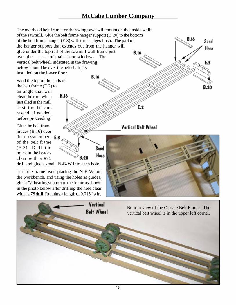
The overhead belt frame for the swing saws will mount on the inside wallsof the sawmill. Glue the belt frame hanger support (B.20) to the bottomof the belt frame hanger (E.3) with three edges flush. The part ofthe hanger support that extends out from the hanger willglue under the top rail of the sawmill wall frame justover the last set of main floor windows. Thevertical belt wheel, indicated in the drawingbelow, should be over the belt shaft justinstalled on the lower floor.
Sand the top of the ends ofthe belt frame (E.2) toan angle that willclear the roof wheninstalled in the mill.Test the fit andresand, if needed,before proceeding.Glue the belt framebraces (B.16) overthe crossmembersof the belt frame(E.2). Drill theholes in the bracesclear with a #75drill and glue a small N-B-W into each hole.
Turn the frame over, placing the N-B-Ws onthe workbench, and using the holes as guides,glue a 'V' bearing support to the frame as shownin the photo below after drilling the hole clearwith a #78 drill. Running a length of 0.015” wire
Bottom view of the O scale Belt Frame. Thevertical belt wheel is in the upper left corner.

19
RLWRLWRLWRLWRLWthrough the bearing supports will help keep them in alignmentwhile gluing.
Drill the centers of the seven large drive wheels clear witha #78 drill. Cut two lengths of 0.015" wire a scale 7.5'long and cut one length a scale 5' long. File the ends smooth,and use them to install the drive wheels as shown in thephoto on page 18. Center the wheels between the bearingsupports and glue all the outer wheels in place; the twocenter wheels will need to be positioned over the drivewheels of the swing saws before gluing into place.
The sheet with the various widths of bond paper stripsshould be painted with Floquil Rail Brown to be usedfor the belts. Choose a width close to the size of thewheels. Belts need to be installed on the two outer setsof wheels as shown in the photo on page 18. Twolengths of belt may need to be glued together end-to-end to make it long enough to fit; a small overlap willwork. Glue to the wheels with ACC.
The vertical belt will be glued to the end drive wheeland trimmed to fit inside the belt shaft without hittingthe floor. Glue it to the drive wheel and test the fitbefore trimming. The lower ends can be glued to a smallscrap of wood to help keep them straight.
Glue the belt frame into the notches of the belt framehangers (E.3) with the vertical belt inside the belt shaft.Position the center wheels over the drive wheels of theswing saws and glue them in place. Belts need to be run
from these center drive wheels down to the small drivewheels on the swing saws. It will be easier to simply formtwo belts into 'U' shapes then glue them to the small drivewheels on the swing saws. The upper ends can then berolled around the large drive wheels on the belt frame andglued in place.
Sawfiler's FloorDuring the sawmill assembly, the safety railings should havebeen added around the openings in the sawfiler's floor asshown below. If not, do so now!
The band saw blades are hoisted up from the main floorfor sharpening and repair. The A-frame hoists are nowadded over the openings as follows. Glue the hoistbeams (A.6) to the tops of the hoist frames (A.5).
Glue a hoist pulley bracket (B.13) into one slot on thebottom of the hoist beam, place a grooved pulley into

McCabe Lumber Company
20
the hole, and glue the second bracket (B.13) into the otherslot. Glue a small N-B.W into the holes on the outside ofthe pulley brackets.
Glue the upper brace (F.9) and the lower brace (F.8) toeach side of the hoist frame. Glue each completed hoistinserted into the opening in the sawfiler floor.
Cut two 1" lengths of chain. Run one over each pulley, andsecure one end to one of the safety railing posts on theopen end of the hoist opening as shown in the photo onpage 22.
Assemble the twoworkbenches bygluing legs (A.10)into the notchesof the sub-tops(B.12). Before theglue dries, insert ashelf (C.2), boardside up, betweenthe legs. Whenthe legs are dry,glue these shelves to the cross boards of the legs. Thetops (C.1) glue down to the assembly with the backflush with the rear edge of the frame and the scribedside up. Stain these with either oak stain or paint, andweather heavily with gray washes.
Paint the grinders orange with dark gray wheels andglue to one end of each workbench. Paint the laser-cutsquares, triangles, and files (G.4, G.5, G.6, G.7) GrimyBlack and glue to the workbenches. The tool setcastings, hammers, lube cans, tongs, blow torches, etc.,and assorted cans & junk can be painted as desired andadded to the workbenches or the shelves. Glue theworkbenches about 3/64" out from the side walls of
the sawfiler's area.
The two shelving units areassembled using threevertical sides (C.5) - the topof these has a notch - andfour shelves (F.4); start bygluing the shelves to thecenter vertical piece first,then adding the other twopieces. Glue in place 3/64"
out from the back wall next tothe door.
Glue a blade hub (G.2) to eachside of the round saw blades(G.1) centered over the hole.Paint these silver and weatherwith rust. Glue around thesawfiler's area.
Assemble the blade holders by gluingthe base (F.1) into the slot on the bottomof the holder (F.2).
Glue the ends of the band saw blades(G.3) together to form loops. Glue sixor more blade holders to each of two ofthe blades and glue these into the openareas of the sawfiler's floor. The othertwo blades can be stacked on the floorout of the way or tossed around theoutside of the mill. The extra blade holders can be setaside as shown below.
Assemble the ladder by gluing the rungs (C.4) into the slotson the rails (C.3) to form the ladder as follows. Glue arung into the end slots to tie the rails together. Allow theseto dry completely, and add the remaining rungs. When all
are dry, sand the sidesof the rails smooth,paint and lay around thearea against a wall.
The sawhorses areassembled by gluingthe beams (D.2) intothe notch at the top ofthe legs (D.1). There are
21
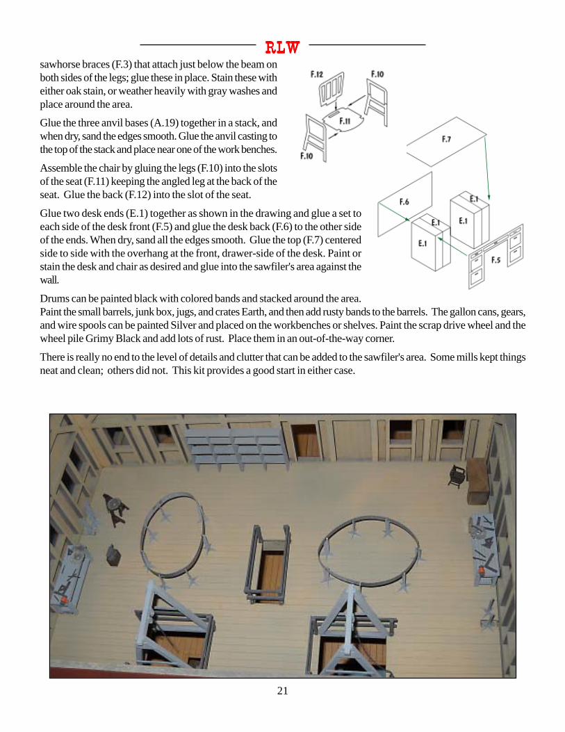
RLWRLWRLWRLWRLWsawhorse braces (F.3) that attach just below the beam onboth sides of the legs; glue these in place. Stain these witheither oak stain, or weather heavily with gray washes andplace around the area.
Glue the three anvil bases (A.19) together in a stack, andwhen dry, sand the edges smooth. Glue the anvil casting tothe top of the stack and place near one of the work benches.
Assemble the chair by gluing the legs (F.10) into the slotsof the seat (F.11) keeping the angled leg at the back of theseat. Glue the back (F.12) into the slot of the seat.
Glue two desk ends (E.1) together as shown in the drawing and glue a set toeach side of the desk front (F.5) and glue the desk back (F.6) to the other sideof the ends. When dry, sand all the edges smooth. Glue the top (F.7) centeredside to side with the overhang at the front, drawer-side of the desk. Paint orstain the desk and chair as desired and glue into the sawfiler's area against thewall.
Drums can be painted black with colored bands and stacked around the area.Paint the small barrels, junk box, jugs, and crates Earth, and then add rusty bands to the barrels. The gallon cans, gears,and wire spools can be painted Silver and placed on the workbenches or shelves. Paint the scrap drive wheel and thewheel pile Grimy Black and add lots of rust. Place them in an out-of-the-way corner.
There is really no end to the level of details and clutter that can be added to the sawfiler's area. Some mills kept thingsneat and clean; others did not. This kit provides a good start in either case.

McCabe Lumber Company
22

23
RLWRLWRLWRLWRLWMain Details(assumes double line) QTY MATERIAL
Nut-Bolt-Washer, Large 7Nut-Bolt-Washer, Small 63Drive Wheel, Large 7Drive Wheel, Small 2'V' Bearing Support 12Grooved Pulley 17Rollers, 30" 49
Grinder 2Jug 3Small Can 45-Gallon Can 3Small Barrel 230-Gallon Drum 230-Gallon Junk Drum 2Anvil 1Crate 3Hammer 2Tool Set 1Lube Can 2Tong 2Blow Torch 2Tool Box 1Can w/handle 1Scrap Drive Wheel 1Gear 2Wire Spool 2Junk Box 1Drive Wheel Pile 1Jug/Crate Cluster 1
Workers 6
Wire, 0.015" 1Wire, 0.010" 1Chain 3Belt Sheet 1Saw Dust 2
Band Saw Bag 2Edger Bag 2Swing Saw Bag 2Carriage & Track Bag 2
Floor Template 1
A.1 Transfer Frame, Short 4 1/32 plyA.2 Transfer Frame, Long 6 1/32 plyA.3 Transfer Base, Long 6 1/32 plyA.4 Transfer Base, Short 4 1/32 plyA.5 Hoist Frame 4 1/32 plyA.6 Hoist Beam 2 1/32 plyA.7 Control Lever Base, Two Slot 9 1/32 plyA.8 Control Lever Base, Three Slot 3 1/32 plyA.9 Lumber, 24" Boards 5 1/32 plyA.10 Workbench Leg 4 1/32 plyA.11 Roller Side, Long 6 1/32 plyA.12 Roller Side, Short 2 1/32 plyA.13 Roller Top Brace 17 1/32 plyA.14 Roller Bottom Brace 17 1/32 plyA.15 Short Roller Support 1 1/32 plyA.16 Conveyor Base 2 1/32 ply
QTY MATERIAL
A.17 Conveyor Post 12 1/32 plyA.18 Not UsedA.19 Anvil Base 3 1/32 ply
B.1 Deck, Narrow Lower 2 1/64plyB.2 Deck, Narrow Upper, Long 2 1/64plyB.3 Deck, Narrow Upper, Short 2 1/64plyB.4 Deck, Wide Lower 1 1/64plyB.5 Deck, Wide Upper 1 1/64plyB.6 Side Rail, Long 2 1/64plyB.7 Side Rail, Medium 4 1/64plyB.8 Side Rail, Short 2 1/64plyB.9 Chain Well Floor, Long 3 1/64plyB.10 Chain Well Floor, Medium 5 1/64plyB.11 Chain Well Floor, Short 2 1/64plyB.12 Workbench Sub-Top 2 1/64plyB.13 Hoist Pulley Bracket 4 1/64plyB.14 Conveyor Arm 6 1/64plyB.15 Conveyor Lever 2 1/64plyB.16 Belt Frame Brace 7 1/64plyB.17 Belt Wall Side, Left 1 1/64plyB.18 Belt Wall Side, Right 1 1/64plyB.19 Belt Wall Front 1 1/64plyB.20 Belt Frame Hanger Support 2 1/64ply
C.1 Workbench Top 2 1/64plyC.2 Workbench Shelf 2 1/64plyC.3 Ladder Rail 2 1/64plyC.4 Ladder Rung 7 1/64plyC.5 Shelf Side 6 1/64ply
D.1 Sawhorse Leg 4 1/32 plyD.2 Sawhorse Beam 2 1/32 plyD.3 Wheel Safety Post 2 1/32 ply
E.1 Desk End 2 1/32 plyE.2 Belt Frame 1 1/32 plyE.3 Belt Frame Hanger 2 1/32 plyF.1 Blade Holder Base 20 1/64 PlyF.2 Blade Holder 20 1/64 PlyF.3 Sawhorse Brace 8 1/64 PlyF.4 Shelf 8 1/64 PlyF.5 Desk Front 1 1/64 PlyF.6 Desk Back 1 1/64 PlyF.7 Desk Top 1 1/64 PlyF.8 Hoist Lower Brace 4 1/64 PlyF.9 Hoist Upper Brace 4 1/64 PlyF.10 Chair Leg 2 1/64 PlyF.11 Chair Seat 1 1/64 PlyF.12 Chair Back 1 1/64 PlyF.13 Wheel Safety Rail 4 1/64 Ply
G.1 Round Saw Blade 12 White CardG.2 Round Saw Blade Hub 24 White CardG.3 Band Saw Blade 4 White CardG.4 Square 3 White CardG.5 Triangle 4 White CardG.6 Large File 5 White Card

McCabe Lumber Company
24
QTY MATERIAL
G.7 Small File 5 White CardG.8 Dog 42 White Card
H.1 Control Lever 27 1/64 Ply
I.1 Lumber, 24" Boards 8 1/32 BassI.2 Lumber, 12" Boards 12 1/32 Bass
J.1 Hog Chute Base 6 1/32 Ply
K.1 Hog Chute 6 White Card
All information in this instruction manual is the sole property ofR.L.W.. and may not be reproduced in any manner without
written permission. Copyright 2011
Republic Locomotive Works 16 Little Cape Horn Cathlamet, WA. 98612R.L.W.R.L.W.R.L.W.R.L.W.R.L.W.

25
RLWRLWRLWRLWRLW

McCabe Lumber Company
26

27
RLWRLWRLWRLWRLW
