slags & mattes in vanyukov's process for the extraction of...
TRANSCRIPT

Slags & mattes in Vanyukov's process for the extraction
of copper
S. Vaisburdi, A. Berneri, D.G. Brandoni, s. Kozhakhmetov2, E. Kenzhaliyev2, R.
Zhalelev2
ipaculty of Materials Engineering, Technion - Israel Institute of Technology, Haifa
32000, Israel
2Institute of Metallurgy and Ore Beneficiation, Almaty 480 I 00, Kazakstan
ABSTRACT
Slags and matte in Vanyukov's process, an autogeneous method of processing sulfide
concentrates of non-ferrous metals used in a specially designed furnace at the
Balkhash copper-smelting plant (Kazakstan), have been characterized by scanning
electron microscopy, energy dispersive spectroscopy and X-ray diffraction. The
liquid matte was shown to have contained 3.6 wt pct of slag inclusions and about 4 wt
pct of magnetite. The solid matte is a mixture of sulfide phases. The liquid waste
slag was shown to have contained 0.6 wt pct of matte inclusions and about 3 wt pct of
magnetite. The silicate field of the solid slag consists of two phases, identified as iron
orthosilicate and iron metasilicate. It was shown that most slag formation occured
before the over-current stage of the process. Metal losses in the slag were found to
take three forms: mechanical (matte inclusions entrained in the liquid slag), chemical
(metal oxide formation) and physical (metal sulfides dissolved in the liquid slag).
Thermodynamic calculation of the exchange reactions for the oxide and sulfide
components of the slag showed that zinc and lead dissolved in the slag are present
mainly as chemical losses but with only a small part (10-20 pct) in the form of
physical losses. By contrast, copper losses occur only ,as mechanical and physical
losses. The results of these thermodynamic calculations are supported by the
experimental data.

Slags & mattes in Vanyukov's process for copper
extraction
s. Vaisburdl, A. Bernerl, D.G. Brandonl, s. Kozhakhmetov2, E. Kenzhaliyev2, R.
Zhalelev2
lPaculty of Materials Engineering, Technion - Israel Institute of Technology, Haifa
32000, Israel
2Institute of Metallurgy and Ore Beneficiation, Almaty 480100, Kazakstan
I. INTRODUCTION
Vanyukov's process of copper extraction is an autogeneous method for sulfide
concentrates of non-ferrous metals present in a liquid matte-slag emulsion. Melting is
accomplished in a specially designed furnace for the continuous counter-flow of matte
and slag melts during the reaction [1]. The most prominent features of this method
are: (1) high productivity (2.1-3.3 ton·m-2·h-l); (2) low dust loss (about 1 pct of the
charge weight); (3) possible charge processing without complete drying (up to 6-8 pct
moisture); (4) possible processing oflump materials (down to 50 mm). Vanyukov's
process has been put in production at some metallurgical plants in Russia and
Kazakstan, but the slags and mattes formed have not been extensively studied. The
primary purpose of the present research was to analyze the chemical and phase
composition of slag and matte and determine the metal losses in the slags. In the
present paper we present data from the Balkhash mining-metallurgical plant. For
additional technological details the reader is referred to Ref. [1, 2].
1

II. EXPERIMENTAL
A. Materials
Samples of slags and matte were obtained from Vanyukov's furnace at the
Balkhash mining-metallurgical plant. Slag samples were taken at the end of the
process (waste slag) and from the over-current zone. The over-current is the region in
V anyukov' s furnace where the slag is released from the melting zone into the
electrothermic settling tank [1]. The results of chemical analysis of the samples are
given in Table I.
B. Sample preparation
Sections were cut from the samples using a diamond wheel before being mounted
in epoxy resin. The sections were ground sequentially on 240, 320, 400 and 600 grit
silicon carbide papers and polished with 3 and 1 Ilm alumina. For scanning electron
microscopy and energy dispersive spectroscopy the specimens were subsequently
carbon coated to ensure electrical conductivity.
c. Scanning Electron Microscopy (SEM) and Energy Dispersive Spectroscopy
(EDS).
Phase and elemental analysis of the specimens using SEM and EDS was
conducted on an XL30 (Philips, Holland) scanning electron microscope equipped with
a LINK ISIS (Oxford Instruments, England) energy dispersive spectrometer. The
measurements were performed at an accelerating voltage of 20 kV, a probe current of
1 nA and a working distance of 10.5 mm. Under these analytical conditions the probe
2

•
diameter on the sample surface was about 100 nm. The morphology of the different
phases at the sample surface was imaged using back-scattered electrons in
compositional contrast mode. After imaging in scanning mode, the electron probe
was positioned sequentially at specific points on the sample surface and EDS spectra
were collected. The take off angle for x-ray radiation collection was 35° and the
spectra acquisition time was set at 100 s. In all cases the standard deviation of the
measured intensity in a single measurement did not exceed 5 pct. Quantitative
microanalysis was performed using the conventional ZAF correction procedure
included in the LINK ISIS software. The final results were normalized to 100 pct. In
order to analyze quantitatively small sub-micron particles directly a correction
technique was used specially developed for this type of analysis [3,4].
D. X-Ray Diffraction (XRD) Analysis.
XRD spectra were obtained with the Bragg-Brentano focusing scheme in a Philips
Analytical PW3020 powder diffractometer at 40 kV and 40 rnA. Diffraction patterns
were acquired from polished samples in a step mode with 0.02° steps (2 ) and 4 s per
point over diffraction angles from 20° to 90°.
III. RESUL TS
A. Matte
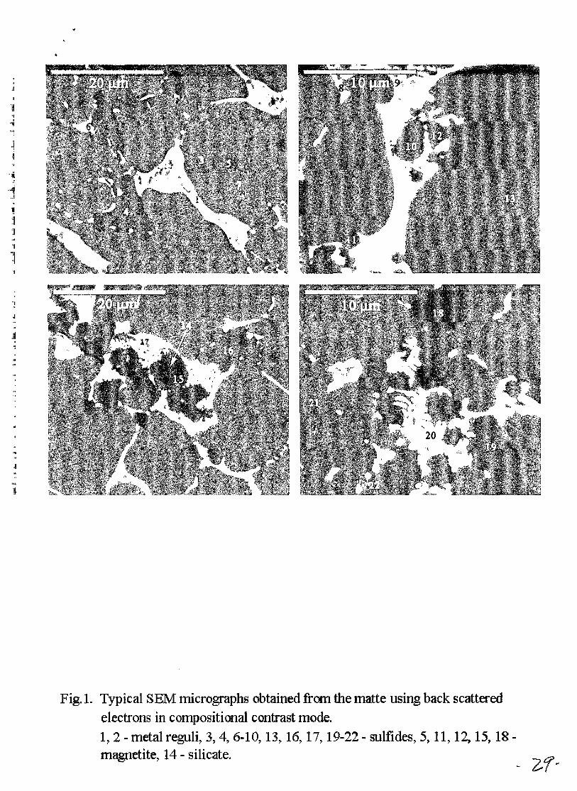
Typical SEM images obtained from the polished surface of the matte specimen are
presented in Fig.1. The complex contrast is inherent in a multiphase structure. The
EDS spectra were collected from different positions on the sample surface marked by
numbers 1-22 in Fig.I. The results of quantitative X-ray microanalysis are shown in
Table II. The structure consists of various sulfides, oxides and reguli of metal alloys.
The average compositions determined for the maj or constituent phases are presented
3
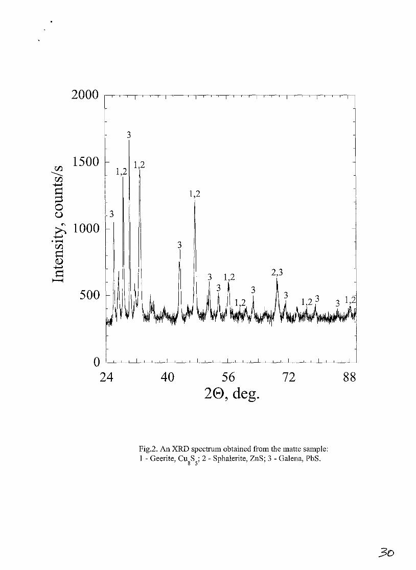
in Table III, and the XRD spectrum taken from this sample is shown in Fig.2. The
interpretation of the XRD data is complicated by peak overlap due to the presence of a
large number of multielement phases. Most peaks in the XRD spectrum can be
attributed to three sulfide phases: CUsSs (Geerite; JCPDS, Standard Diffraction
Pattern, # 33-0491 [5]), ZnS (Sphalerite, JCPDS, #. 05-0566) and PbS (Galena,
JCPDS, # 05-0592). Slight discrepancies between the measured and the standard
peak positions can be explained by atomic substitution of different metals (Cu, Fe, Zn,
and Pb) for the specified metal atom in the standard chemical formulae. The XRD
results are in agreement with the results of chemical analysis for the major phases
(Table III). For example, the sulfide phase, which is a major component (more than
85 pct), is in our case (Cuo.76Feo.24)sSs rather than CusSs. The rest of peaks in the XRD
spectrum can be attributed to diverse sulfides (CuS, (Cu, Fe, Pb)S, FeS2, CUl.92S) and
magnetite (Fe304), which were also observed in the sample point analyses using EDS.
B. Slag from the over-current zone
A typical morphology of the sample surface is shown in Fig.3. The major part of
the surface consists of the dark dendritic background. Two additional phases are
observed as grey rectangular or trapezoid 5-15 !-lm particles and white coarse (1-7 !-lm)
or fine (up to 1 !-lm) oval interdendritic particles. Area measurements showed that the
relative surface fractions of these phases are approximately 94.3 pet, 5.5 pct and 0.2
pct, respectively. Some fields of view also contained large particles (several hundreds
of micrometers), with a morphology similar to that of the matte sample (see, Fig.4).
The results of EDS analysis from different positions in these large particles clearly
show that these macro-particles consisted of phases characteristic of the matte sample.
We conclude, that the macro-particles are matte mechanically entrained in the slag
during the melting process.
4

The results of EDS analysis averaged over many points for each phase present in
the sample are listed in Table IV, and the XRD spectrum taken from this sample is
shown in Fig.5. All diffraction peaks in the XRD spectrum can be attributed to just
two phases: (Fe, Mg)2Si04 (Fayalite magnesian; JCPDS, # 07-0158) and Fe304
(Magnetite, JCPDS, # 19-0629). Some peaks could be attributed altematively to a
phase of FeSi03 (Clinoferrosilite, JCPDS, #17-0548) but strong overlap between all
peaks of this phase with peaks of (Fe, Mg)2Si04 makes unambiguous interpretation
impossible. The EDS results support this interpretation. The chemical composition
of the dendrites is in good agreement with the composition of iron orthosilicate
Fe2Si04, with iron partially replaced by different cations (Zn, AI, Mg, K, Ca, and Ba).
The chemical composition of the interdendritic regions is close to that for iron
metasilicate FeSi03. The slight difference in contrast between the dendrites and the
interdendritic regions depends m~inly on the iron content with the higher iron
concentration giving the lighter contrast. The chemical composition of the grey
rectangular or trapezoid particles corresponds to that of magnetite Fe304, which
agrees with the XRD results. White coarse and fine oval particles of the third phase,
whose small volume fraction (less than 1 pct) cannot contribute to the XRD pattem
were found to be sulfides: mainly (Cu, Fe)S. The mean chemical composition of
these particles, averaged over 30 particles, is close to that of the (Cu, Fe)8SS phase,
which is the major component of the matte (see Table III). Several sulfide particles
had compositions, which deviated significantly from the mean composition. In
particular, many particles corresponding to ZnS, (Cu, Fe, Zn)S, (Pb, Cu, Fe)S and
(Cu, Fe, Zn, Pb)S were also observed.
5

C. Waste slag formed at the end of the process
A typical morphology of the sample surface is shown in Fig.6. As in the slag
from the over-current zone, most of the surface consists of the dark dendritic
background. The two other phases present are grey dendrites or rectangular and
trapezoid particles and white coarse or fine oval particles. Large macro-particles of
the matte were not found. Areal measurements showed that the relative surface
fractions of the observed phases are approximately 96.0 pet, 3.5 pet and 0.8 pet,
respectively. These results correspond closely to those for the sample of slag from the
over-current zone. No difference between the XRD spectra from these two slags
could be detected. The average results of EDS analysis over many points for each
phase are listed in Table V. Again the major constituent phases in these two slags
have similar chemical compositions.
IV. DISCUSSION
A. Matte
The solid matte contains two types of oxide inclusion: magnetite, which was
dissolved in the liquid matte and precipitated during cooling, and slag inclusions that
were present in the liquid matte as a dispersed phase. In order to calculate the
chemical composition of the slag inclusions in the matte one can use the known fact
that silica is insoluble in the sulfide melt. It follows that any silica observed in the
matte composition must originate from one of the slag oxides. The ratios of the
contents of all oxides to the silica content in the slag were derived from the chemical
analyses (Table I, row 3) and were then used to calculate the contents of other slag
oxides in the matte. These data are given in Table VI (row 1). Note that the CaO
concentration calculated in this way coincides, within experimental error, with that
6

determined in the matte by chemical analysis (see Table I), which further confirms the
above calculation method since calcia like silica is insoluble in the matte. The total
content of slag inclusions in the matte is 3.6 wt pct. The average chemical
composition of the slag inclusions was calculated by normalizing the data to 100 pct
(Table VI, row 2). For comparison, Table VI also gives the mean composition of the
slag inclusions in the matte determined by EDS (row 3) and the slag composition
determined by chemical analysis (row 4). The agreement is satisfactory and the
discrepancies can be explained by errors in the analysis data and the presence in the
slag of some oxides (K20, BaO, Na20, MgO, and Ti02), which were not determined
by chemical analysis.
The matte composition is given in Table VII, where the atomic fractions of Fe,
Cu, Zn and Pb have been transformed to the corresponding sulfide contents. The
matte can only consist of the lowest sulfides (that is, Cu2S, FeS, PbS and ZnS) [6].
According to the present results the sulfide, which occupies more than 85 pct of the
matte volume, has the crystal structure of geerite (CusSs or 3CU2S·2CuS). Atoms of
CUll in this sulfide should be replacable by atoms of Fell, ZnIl or PbIl, so that this
sulfide should have a composition (Cuo.7sMeo.2s)sSs, where Me denotes a sum of the
Fe, Zn and Pb. This corresponds exactly with the mean chemical composition of the
sulfide determined by EDS (see Table III).
Some deficiency of sulfur in the matte was noted and was attributed to
metallization of the matte by copper. This metallization was also confirmed by the
SEMIEDS results (see Fig.I, where metal reguli (Cu and AgCu) are clearly visible in
the matte). Although the Cu-S system has a tendency to exfoliate in the liquid state,
even at low sulfur depletion [7], the presence of other metals in the matte prevents
separation of a metallic phase in the liquid state, and the observed metallic phases are
7
a result of liquation during cooling. The residue of 4.4 wt pct should be apparently
assigned to magnetite, which is contained in the matte but was not determined by the
chemical analysis, although the SEMIEDS results clearly demonstrate the presence of
magnetite in the matte. Another possibility is the presence of oxygen dissolved in the
melt, which also was not determined. The normalized matte composition is given in
Table VII, row 2. The content of copper in the matte is higher, and of iron and sulfur
lower, than their contents in mattes produced by conventional technologies [8, 9].
This is a characteristic feature of an autogeneous process where melting is achieved at
higher oxygen potentials.
B. Slag
The SEMIEDS data show that the silicate field of the solidified slag consists of
two interpenetrating phases, gray and black. The crystal structure and chemical
composition of the grey phase corresponded to iron orthosilicate where iron was
partially replaced by several different cations (Zn, Mg, Ca, and Ba). The relatively
low iron content (16.1 atomic pct instead of 28.6 atomic pct expected from the
stoichiometry of Fe2Si04) could explain why this phase crystallized as fayalite
The structure and chemical
composition of the black phase corresponds to iron metasilicate. The results of
chemical analysis presented in Table I support this interpretation: the silica
concentration in the liquid slag is about 34 wt pct intermediate between the silica
content in iron orthosilicate (29 wt pct) and that in iron metasilicate (45 wt pct).
The average concentrations of oxides in both slag samples obtained by EDS are
listed in Table VIII. The silicate compositions of these slags are very close, which
strongly suggests that the process of slag formation is completed before the
over-current zone, that is the interaction between matte and slag melts is near to the
8

equilibrium state. Table I shows that the average values for the contents of all
elements in both these slags are also very close, although one exception is the copper
content. The higher copper content in the slag from the over-current zone shows that
the process of sedimentation of matte reguli was not complete before the over-current
zone. In addition, the slag from the over-current zone contains large matte particles
(300 !lm and more) while the waste slag only contains small matte reguli.
Both slags contain two types of inclusions, which were identified as magnetite and
matte reguli. The regular shape of the magnetite inclusions is evidence for their
precipitation during cooling of the liquid slag. By contrast, the rounded and oval
shapes of the matte reguli suggest that they were in the liquid state in the slag. These
inclusions determine the mechanical losses of metals in the waste slag. The chemical
composition of the matte reguli in the waste slag was calculated using a similar
approach to that used for the calculation of the slag inclusion composition in the
matte. It is known [6] that copper does not form oxide in slag when in the contact
with a sulfide melt, so that the copper observed in the slag composition is originated
from the matte reguli. The ratios of the contents of all matte components to the
copper content in the matte were determined from the chemical analysis data (Table I,
row 1) and used to calculate their contents in the waste slag. These data are listed in
Table IX (row 1). The total content of matte reguli in the slag is equal to about 0.6 wt
pct, which is in good agreement with the areal measurements obtained by SEM (0.8
pct). The average chemical composition of the matte reguli was determined by
normalizing the calculated data to 100 pct (Table IX, row 2). For comparison, Table
IX also gives the mean composition of the matte reguli in the slag determined by EDS
(row 3) and the matte composition determined by chemical analysis (row 4). There is
satisfactory agreement.
9

C. Metal losses in slag
A major question is the partitioning of metals between oxides and sulfides when
they are dissolved in slag, since zinc, lead and also iron are present in solution in the
silicate melt as both oxides and sulfides. This brings us to the problem of non-ferrous
metal losses in liquid waste slags.
The ionic theory of liquid slags [10] has demonstrated that all chemical
compounds dissolved in slag, including sulfides, are ionically dissociated. In
accordance with this idea, it was postulated that metal particles derived from MeO and
MeS in the slag should be indistinguishable, since in both cases dissociation yields the
same cation Me ++ [9]. As a result, only two forms of metal losses in the slag were
considered: mechanical (matte inclusions) and dissolved or electrochemical (dissolved
oxides and sulfides together) [9].
However, one of the authors has shown [6] that oxides and sulfides dissolved in
slag may behave differently: the sulfides of transitional metals do not necessarily
dissociate in the ionic melt as discussed in [11], so that there are three different forms
of metal losses: mechanical, chemical (dissolved oxides giving cations in the liquid
slag) and physical (dissolved sulfides, without dissociation) [11].
Consider a heterogeneous system consisting of two homogeneous phases: liquid
slag and liquid matte. Slags in non-ferrous metallurgy always contain iron oxide and
the behavior of different metal compounds dissolved in the slag are determined by the
chemical equilibria of the following reactions that take place in the liquid state:
(FeO) + (MeS) = (FeS) + (MeO),
(FeO) + [MeS] = [FeS] + (MeO),
[MeS] = (MeS),
10
(1)
(2)
(3)
where Me is a non-ferrous metal, the round brackets denote the homogeneous liquid
slag and the square brackets denote the homogeneous liquid matte. Since the
equilibrium in this complicated system is always conjugated, any shift of the
equilibrium in reaction (1) to the right will also leads to a shift of the equilibrium of
the heterogeneous reaction (2) to the right. Consequently, when the (MeS)
concentration is low, that is dissolution of the sulfide in slag, reaction (3) practically
does not proceed, and the metal is dissolved in the slag mainly in oxide form. By
contrast, if the reaction (1) is shifted to the left, then sulfide is dissolved in the slag,
and the equilibrium of reaction (3) is then shifted to the right. We conclude that the
chemical state of non-ferrous metals dissolved in liquid slag is determined by the
conjugated equilibrium of all three reactions (1), (2) and (3). The same conclusion
should be true for systems where sulfur is substituted by other metalloids such as
selenides, tellurides, arsenides or silisides [6].
A thermodynamic calculation for reaction (1) was made based on data given in
Ref. [12, 13]. The calculation used the first approximation of Ulich's formula [14],
which is justified provided that the value of the parameter M, below, is less than
errors in the values of ~Hs and ilSs, where ~Hs and ilSs are the enthalpy and the
entropy change of the reaction (1) under standard conditions. The parameter M is
calculated from the relation:
(4)
where ~c! is the heat capacity change for reaction (1) under standard conditions, T is
the absolute temperature and Mo = In(T/298) - 1 + 298fT. The above critical
conditions for using the first approximation should be met for the present case.
The slag is released from the furnace at 1300D C so this temperature was used
for the calculation. However, the oxides considered are solid at this temperature
11

whereas they are liquid when dissolved in the slag. Therefore the latent heat of
melting for the oxides and their heat capacity in the liquid state were included in the
calculation.
The results of the calculation of the equilibrium constants K are given in Table
X, which also lists the ratio of the equilibrium contents of sulfide and oxide derived
from equation (1) for the metals in question C(MeS/C(MeO):
C(MeS) = Ky . C(FeS)
C(MeO) K C(FeO)
(5)
where Ky = Ilri and r)s the activity coefficient of the component i. The value of
K y C(FeS) / C(FeO) was estimated to be about 0.01 [11].
For comparison, Table X also lists data calculated for cobalt, whose partition
between slag and matte is well known [6, 9]: cobalt dissolves in the slag mainly in the
oxide form. Zinc is similar to cobalt in its behavior and the value of C(ZnS/C(ZnO)
should be close to that of C(cos/C(coO)' As it can be seen from Table X the
corresponding values are 0.12 for cobalt and 0.11 for zinc, which supports this
calculation method. Lead dissolved in the slag is present mainly in the oxide form
(with only 20 pct in the sulfide form). By contrast, copper is dissolved in the slag
only in the sulfide form, as is known [6, 9].
These conclusions are confirmed by the present SEMIEDS results.
Comparison of the total zinc content in the liquid slag (Table I, row 3) with that in the
silicate portion of the slag (Table VIII) shows clearly that zinc similar to cobalt exists
in the liquid slag mainly as oxide. Lead shows the same behavior. Small reguli,
educed by liquation from the slag, are sulfides mainly of copper and iron; with zinc
and lead present in very small quantities according to the data of Table X. The
12

..
sub-micron sulfide inclusions of oval shape differ widely in composition from the
average matte composition and are evidence of the predicted physical losses. Thus,
the physical losses of zinc and lead are very small, and these elements are mainly
dissolved in the slag in the form of chemical losses, while copper gives only physical
losses.
V. CONCLUSIONS
The slags and matte from Vanyukov's process, an autogeneous processing method
of sulfide concentrates of non-ferrous metals used at the Balkhash copper-smelting
plant (Kazakstan), were characterized by scanning electron microscopy, energy
dispersive spectroscopy and x-ray diffraction. The following, results and conclusions
were obtained:
1. The liquid matte contains 3.6 wt pct of slag inclusions and about 4 wt pct of
magnetite. The solidified matte is a mixture of sulfides in which the major, matrix
component was identified as geerite, (Cu, Fe)8SS. The content of copper in the
matte is higher, and of iron and sulfur lower, than in mattes produced by
conventional technologies.
2. The liquid waste slag contains 0.6 wt pct of matte inclusions and about 3 wt pct of
magnetite. The silicate field of the solidified slag consists of two phases, which
were identified as iron orthosilicate and iron metasilicate. It was proved that slag
formation was essentially complete before the over-current zone.
3. The nature of metal losses with the waste slag was considered. Three forms of
losses were identified: mechanical (matte inclusions in the liquid slag), chemical
(metal oxides) and physical (metal sulfides dissolved in the liquid slag).
13

4. A thermodynamic calculation was made of the exchange reactions between oxide
and sulfide components in the slag. The ratio of the sulfide and oxide forms of
non-ferrous metals in the liquid slag from Vanyukov's furnace was estimated.
The calculation showed that zinc and lead were present in the slag mainly as
chemical losses and only partially (10-20 pct) in the form of physical losses. By
contrast, copper gives only physical losses. The present experimental results
support these conclusions.
ACKNOWLEDGMENTS
This research was supported under Grant No. TA-MOU-98-CA17-017
Program in U.S.-Israel Cooperative Development Research Program, Economic
Growth, U.S. Agency for International Development.
14

Table I. Chemical analysis (wt pct) of melt products from Vanyukov's furnace
Sample Cu Fell S CaO Si02 Fe3O", Ah0 3 Zn Pb Total
measured
Matte ' 48.90 16.48 22.1 0.12 1.30 - 1.35 3.60 2.50 96.38
Over-current 3.80 30.90 1.8 2.50 31.70 2.40 5.40 6.50 1.26 94.98
slag
Waste slag 0.31 32.40 1.9 2.90 33.80 3.20 5.10 6.30 1.20 95.05

Table II. EDS analysis of the matte
Position Measured content of element, atomic pct Major elements I
Fe Cu Zn Pb S K Ca Ba Si 0 Ag
1 2.51 20.91 0.23 6.09 2.72 - - - - - 67.4 Ag-Cu
2 2.01 97.31 0.22 0.05 0.37 0.01 Cu
3 14.35 43.74 0.26 0.02 41.7 - - - - - 0.03 Cu-Fe-S
4 11.16 2.24 36.31 0.01 50.17 - - - - - 0.01 Zn-Fe-S
5 33.4 4.84 0.92 0.05 4.35 - - - - 56.45 0.02 Fe-O
6 12.36 5.81 19.5 16.43 45.51 - - - - - 0.16 Cu-Fe-Zn-Pb-S
7 8.75 52.65 0.13 0.04 38.32 - - - - - 0.04 Cu-Fe-S
8 8.39 21.44 0.51 27.04 42.66 - - - - - 0.05 Pb-Cu-Fe-S
9 7.54 21.57 0.32 27.86 42.77 - - - - - 0.04 Pb-Cu-Fe-S
10 15.61 1.89 32.25 0.74 49.5 - - - - - 0.05 Zn-Fe-S
11 27.14 8.35 0.84 1.15 9.18 - - - - 53.51 - Fe-O
12 33.48 1.38 1.16 1.29 2.88 - - - - 59.78 - Fe-O
13 14.09 44.44 0.19 - 41.49 - - - - - - Cu-Fe-S
.-/6 .:

Table II. Continuation
Position Measured content of element, atomic pct Major elements
Fe Cu Zn Pb S K Ca Ba Si 0 Ag
14 21.52 0.58 2.01 0.07 0.62 1.42 1.97 0.32 11.29 60.2 - Fe-Si-O
15 36.81 0.57 1.47 0.02 0.11 - - - - 61.06 - Fe-O
16 11.27 7.29 33.35 - 48.07 - - - - - - Zn-Fe-S
17 11.84 25.19 0.37 21.64 40.55 - - - - - 0.08 Pb-Cu-Fe-S
18 37.71 1.04 1.38 0.03 0.47 - - - 0.76 58.62 - Fe-O I
19 11.69 2.26 34.63 0.24 47.47 - - - - 3.71 - Zn-Fe-S
20 8.01 22.44 1.57 22.43 37.42 - - - - 8.13 - Pb-Cu-Fe-S
21 14.38 41.89 0.12 0.22 38.07 - - - - 5.31 - Cu-Fe-S
22 14.69 37.44 2.21 0.67 38.81 - - - - 6.18 - Cu-Fe-S
·-;1 ~

Table III. Average composition of major phases in the matte
Major Measured content of element, atomic pet Phase
elements Fe Cu Zn Pb Sum of S 0
identification
metals
Cu-Fe-S 12.9±1.3 42.5±2.3 O.6±O.4 O.3±O.1 56.3±3.0 38.3±O.5 5.5±O.2 (Cu, Fe)sSs
Zn-Fe-S 12.1±l.O 3.3±1.2 33.2±O.9 O.2±O.07 48.8±2.0 47.5±O.4 3.7±O.l (Zn, Fe)S
Pb-Cu-Fe-S 8.3±1.0 20.5±1.1 O.6±O.2 24.9±1.5 54.3±2.0 37.8±O.2 7.7±O.7 (Pb, Cu, Fe)S
Fe-O 35.9±O.9 1.9±O.9 1.2±O.l - 39.0±1.5 2.0±1.0 58.7±O.9 Fe304
-_ ... _--
if

Table IV. Average composition of major phases in the over-current slag
Feature Measured content of element, atomic pet Phase
Ph Fe Zn AI Mg K Ca Ba Sum of Si 0 identification
metals
Matrix O.3±O.O8 8.9±O.3 2.8±O.1 4.6±O.3 O.2±O.OS O.8±O.O3 3.S±O.OS O.S±O.Ol 21.6±O.S lS.S±O.2 58.6±O.S Clinoferro-
phase silite,
(black) FeSi03
Matrix O.O7±O.O3 16.l±1.3 2.8±O.1 2A±O.3 1.1±O.O6 O.6±O.1 1.3±O.l O.2±O.OS 24.6±1.S 16.7±O.5 S7.S±O.3 Fayalite
phase magneSian,
(grey) (Fe, MghSi04
~ - --- L-- __ --- - ---
Feature Measured content of element, atomic pct Phase
Fe Cu Al Mg Ti Cr Zn Ph Sum of 0 identification
metals
Rectangular or 33.8±OA 1.6±1.S 2.7±O.8 O.2±O.O7 OA±O.Ol O.3±O.2 2.0±OA O.1±O.O4 41.1±1.9 57.0±1.6 Magnetite
trapezoid grey Fe304
particles
- ~ ---- - - - - ------ --- .. -
11
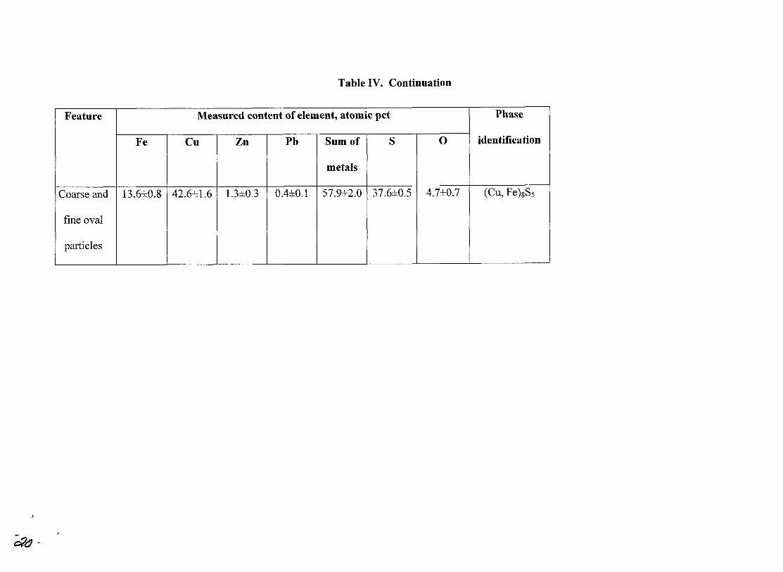
Table IV. Continuation
Feature Measured content of element, atomic pct Phase
Fe Cu Zn Pb Sum of S 0 identification
metals
Coarse and 13.6±O.8 42.6±1.6 1.3±O.3 O.4±O.l 57.9±2.0 37.6±O.5 4.7±O.7 (Cu, Fe)8S5
fine oval
particles
- '----- - - . - .--
~-
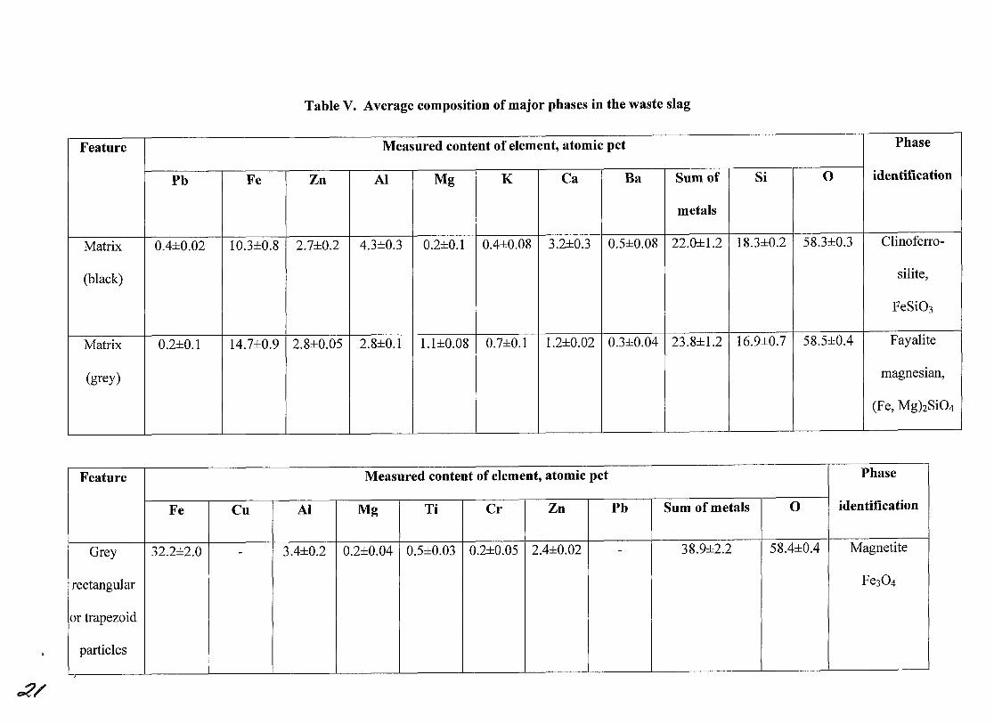
Table V. Average composition of major phases in the waste slag
Feature Measured content of element, atomic pct Phase
Pb Fe Zn Al Mg K Ca Ba Sum of Si 0 identification
metals
Matrix O.4±O.O2 IO.3±O.S 2.7±O.2 4.3±O.3 O.2±O.I O.4±O.OS 3.2±O.3 O.5±O.OS 22.0±1.2 lS.3±O.2 5S.3±O.3 Clinoferro-
(black) silite,
FeSi03
Matrix O.2±O.I I4.7±O.9 2.S±O.05 2.S±O.I I.1±O.OS O.7±O.I I.2±O.02 O.3±O.O4 23.S±1.2 16.9±O.7 5S.5±O.4 Fayalite
(grey) magnesIan,
(Fe, Mg)2Si04
- -- - - --
Feature Measured content of element, atomic pct Phase
Fe Cu Al Mg Ti Cr Zn Pb Sum of metals 0 identification
Grey 32.2±2.0 - 3.4±O.2 O.2±O.O4 O.5±O.O3 O.2±O.O5 2.4±O.O2 - 3S.9±2.2 5S.4±O.4 Magnetite
rectangular Fe304
or trapezoid
particles I
,
,;:('/
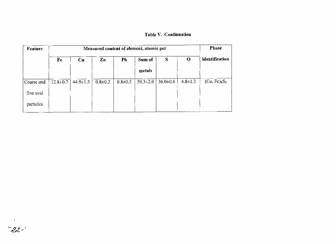
Table V. Continuation
Feature Measured content of element, atomic pct Phase
Fe Cu Zn Pb Sum of S 0 identification
metals I
Coarse and 12.8±O.7 44.9±1.5 O.8±O.2 O.8±O.5 59.3±2.0 36.0±O.6 4.8±1.3 (Cu, Fe)8SS
I
fine oval
particles
-~<?

Table VI. Composition of slag inclusions in the matte (wt pet)
Type of determination Si02 FeO Fe304 CaO Ah03 K20 BaO ZnO PbO Total
Content in the matte 1.30 1.61 0.08 0.11 0.20 - - 0.30 0.02 3.62
Content in slag inclusions in the 35.9 44.5 2.2 3.0 5.5 - - 8.3 0.6 100
matte I
Content in slag inclusions in the 30.1 48.6 5.1 3.5 - 2.9 2.2 7.2 0.4 100
matte determined by EDS
Content in the slag 33.8 41.7 3.2 2.9 5.1 - - 7.8 1.3 95.8
'----- - _L---_ ------ --
:<3.

Table VII. Matte composition (wt pct)
Type of determination FeS CU2S Cu PbS ZnS Total Slag Residue
inclusions
Content in the matte excluding slag 23.9 57.0 3.3 2.8 5.0 92.0 3.6 4.4
and magnetite inclusions
Content in the matte 26.0 61.9 3.6 3.1 5.4 100 - --- - -- -
•
~~
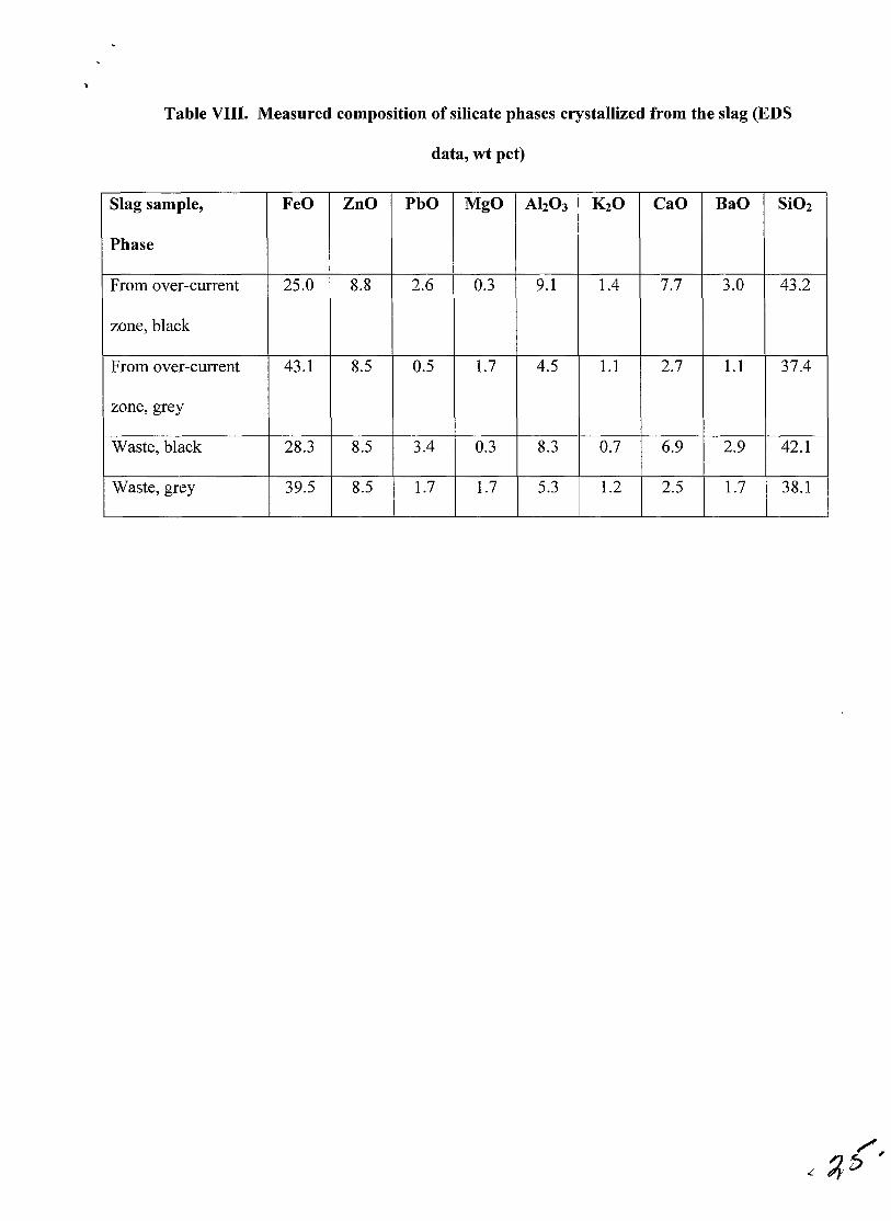
Table VIII. Measured composition of silicate phases crystallized from the slag (EDS
data, wt pct)
Slag sample, FeO ZnO PbO MgO Ah0 3 K20 CaO BaO Si02
Phase
From over-current 25.0 8.8 2.6 0.3 9.1 1.4 7.7 3.0 43.2
zone, black
From over-current 43.1 8.5 0.5 1.7 4.5 1.1 2.7 1.1 37.4
zone, grey
Waste, black 28.3 8.5 3.4 0.3 8.3 0.7 6.9 2.9 42.1
Waste, grey 39.5 8.5 1.7 1.7 5.3 1.2 2.5 1.7 38.1
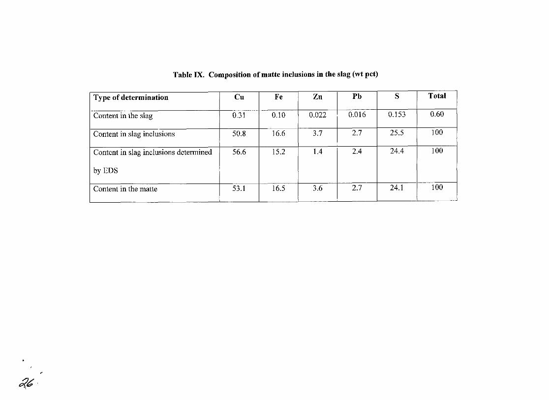
Table IX. Composition of matte inclusions in the slag (wt pet)
Type of determination Cu Fe Zn Pb S Total
Content in the slag 0.31 0.10 0.022 0.016 0.153 0.60
Content in slag inclusions 50.8 16.6 3.7 2.7 25.5 100
Content in slag inclusions determined 56.6 15.2 1.4 2.4 24.4 100
byEDS
Content in the matte 53.1 16.5 3.6 2.7 24.1 100
-
...
~b'
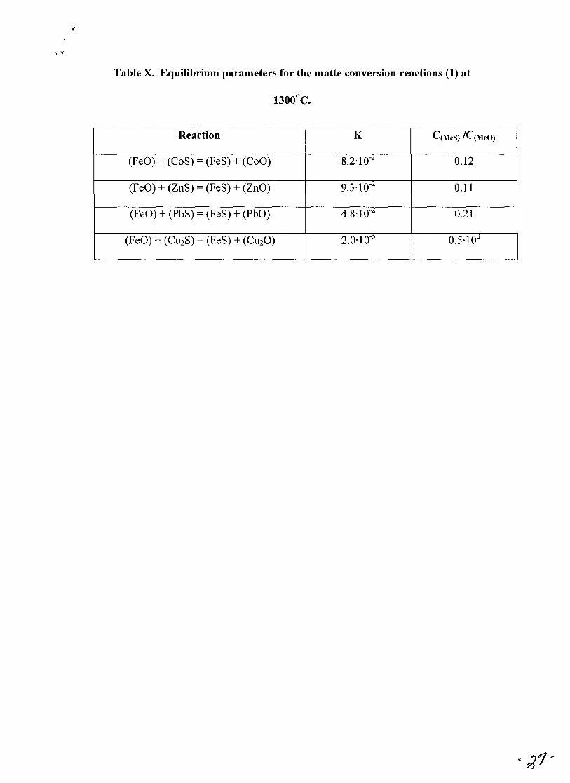
Table X. Equilibrium parameters for the matte conversion reactions (1) at
1300oC.
Reaction K C(MeS) IC(MeO)
(FeO) + (CoS) = (FeS) + (CoO) 8.2.10-2 0.12
(FeO) + (ZnS) = (FeS) + (ZnO) 9.3.10-2 0.11
(FeO) + (PbS) = (FeS) + (PbO) 4.8.10-2 0.21
(FeO) + (CU2S) = (FeS) + (CU20) 2.0·10-) 0.5·lOj

Figure captions
Fig.l. Typical SEM micrographs obtained from the matte using back scattered
electrons in compositional contrast mode. 1, 2 - metal reguli, 3, 4, 6-10, 13, 16, 17,
19-22 - sulfides,S, 11, 12, 15, 18 - magnetite, 14 - silicate.
Fig.2. An XRD spectrum obtained from the matte sample: I-Geerite, CUSS5; 2-
Sphalerite, ZnS; 3-Galena, PbS.
Fig.3. Typical SEM micrographs obtained from slag collected in the over-current
zone. (Back scattered electrons using compositional contrast mode.)
FigA. A matte particle in the slag collected from the over-current zone. SEM image
with back scattered electrons using compositional contrast mode.
Fig.5. An XRD spectrum obtained from a sample of slag collected from the
over-current zone: I-Fayalite magnesian, (Fe, Mg)2Si04; 2-Clinoferrosilite, FeSi03;
3-Magnetite, Fe304.
Fig.6. Typical SEM micrographs obtained from the waste slag with back scattered
electrons in compositional contrast mode.
",ij J
.~
"I
Fig.l. Typical SEM micrographs obtained from the matte using back scattered electrons in compositional contrast mode. 1~ 2 - metal reguli, 3,4, 6-10, 13~ 16, 17~ 19-22 - sulfides~ 5~ 11~ 12, 15~ 18 -magnetite, 14 - silicate.
2000
3
r/'J 1500 1,2 ___ 1,2 r/'J ~
§ 1,2
8 3
~ 1000 .~
r/'J ~ 0)
~ ~
500
3
3 1,2 3 3
2,3
o ~~~~~~~~~~~~~~~~~~~ 24 40 56
28, deg. 72
Fig.2. An XRD spectrum obtained from the matte sample: 1 - Geerite, eu S ; 2 - Sphalerite, ZnS; 3 - Galena, PbS.
8 5
88
30
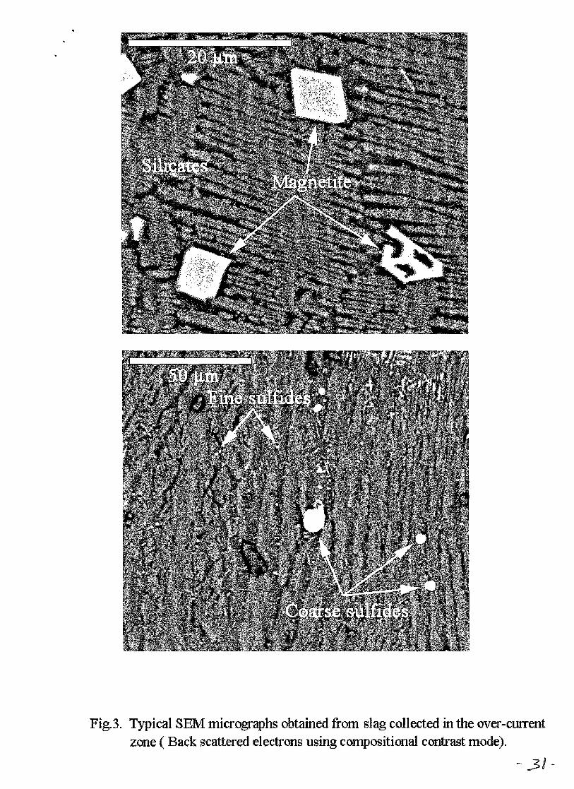
Fig.3. Typical SEM micrographs obtained fronl slag collected in the over-cWTent zone ( Back scattered electrons using compositional contrast mode).
- 31-

Fig.4. A matte particle in the slag collected from the over-current zone.
SEM image with back scattered electrons using compositional
contrast mode.

• ;
250 1,2
1
U"J 200 -- 1 U"J ~
~ ;:l 150 1 0 U 1
.... 1 >-. ~ .~ 100
U"J ~ 2,3 (l)
1,2 1,3 ~
~ 50 1 1,2 3 ~
Fig.5. An XRD spectrum obtained from a sample of slag collected from the over-current zone: 1 - Fayalite magnesian, (Fe, Mg) SiO ; 2 - Clinoferrosilite, FeSiO ; 3 -Magnetite, Fe 0 .
2 4 3 3 4

• .
Fig.6. Typical SEM micrographs obtained from the waste slag with
back scattered electrons in compositional contrast mode.

t
• • •
REFERENCES
1. Smelting in Matte-Slag Liquid Emulsion, ed. A.V. Vanyukov, "Metallurgiya",
Moscow, 1988. (in Russian.).
2. V.N. Malyshev, D.I. Baiguatov, S.M. Kozhahmetov, R.Z. Zhalelev: Proc. Int.
Con! "Environmental improvements in mineral processing and extractive
metallurgy", Univ. Conception Press, Chili, Santiago, 1999.
3. R. Stoyanchev: X-ray spectrometry, 1989, vo1.18, pp.165-171.
4. R. Stoyanchev, Tz. Iliev and K Recalov: : X-ray spectrometry, 1994, vo1.23,
pp.l05-111.
5. Powder Diffraction File, JCPDS, Swarthmore, PA, U.S.A, 1990.
6. S.E. Vaisburd: Physico-Chemical Properties and Structure Features of Sulfide
Melts, "Metallurgiya", Moscow, 1996,304 p. (in Russian.).
7. Binary Alloy Phase Diagrams, ed. T.B. Massalski, 2nd ed., American Society
for Metals, Metals Park, Ohio, U.S.A., 1992, pp.1467-1471.
8. A.V. Vanyukov and V.Ya. Zaytsev: Slags and Mattes of Non-Ferrous
Metallurgy, "Metallurgiya", Moscow, 1969,406 p. (in Russian.).
9. A.V. Vanyukov and V.Ya. Zaytsev: Theory of Pyrometallurgical Processes,
"Metallurgiya", Moscow, 1973,504 p. (in Russian.).
10. O.A. Yessin, P.V. Gueld: Physical Chemistry of Pyrometallurgical Processes,
part 2, Interactions with Participation of Melts, "Metallurgiya", Moscow, 1966,
703 p. (in Russian.).
11. S.E. Vaisburd, N.N. Novikova: Transactions of Inst. Gipronickel, Leningrad,
1970, Vol. 46, pp. 103-110 (in Russian.).
12. O. Kubaschewski and E. Evans: Metallurgical thermochemistry, 3rd ed.,
Pergamon Press, N.Y., 1958,426 p
13. O. Kubashevsky, C. Alcock, P. Spencer: Materials thermochemistry, 6th ed.,
Pergamon Press, Oxford, 1993,363 p.
14. R. Wenner: Thermochemical Calculations, 1st ed., McGraw-Hill Book Co,
N.Y., 1941,384 p.