skymap iiic & tracker iiic pilot guide & operating manual · i skymap iiic & tracker...
TRANSCRIPT

i
Skymap IIIC & Tracker IIIC
Pilot Guide & Operating Manual
Manual Revision: SM2105-08 SIIIC Pilots Guide
Unit Software Version 1.19+ (System Model Packages SM4000 & TR4000)
Aeronautical Database: - Supplied courtesy of Jeppesen®
AND data Ireland LtdCartographic Database - ANDTopographic – NOAA (National Oceangraphic Atmospheric Administration)
2002 Skyforce Avionics Ltd,(A subsidiary of Honeywell Inc)5 The Old Granary,Boxgrove,Chichester,West Sussex PO18 0ES,UK
Information in this document is subject to change without notice. Honeywell reserves theright to change or improve its products and to make changes in the content withoutnotification.

ii
Table of Contents
1 INTRODUCTION.............................................................................................................................. 1-1WARNING ....................................................................................................................................... 1-1DEFINITIONS, ACRONYMS AND ABBREVIATIONS ................................................................... 1-2
Definitions..................................................................................................................................... 1-2Acronyms and Abbreviations. ...................................................................................................... 1-4
A QUICK LOOK AT YOUR UNIT ................................................................................................... 1-6Standard Accessories .................................................................................................................. 1-7Optional Accessories ................................................................................................................... 1-7
2 GENERAL INFORMATION ............................................................................................................. 2-1SOFT KEYING..................................................................................................................................... 2-1SCREEN ORIENTATION ....................................................................................................................... 2-1SOFTWARE ARCHITECTURE ................................................................................................................ 2-1MEMORY LOCATIONS ......................................................................................................................... 2-3SCREEN ICONS .................................................................................................................................. 2-3
3 POWER AND ANTENNA CONSIDERATIONS .............................................................................. 3-1POWER.............................................................................................................................................. 3-1ANTENNA CONSIDERATIONS (SKYMAP IIIC ONLY)................................................................................ 3-3
4 QUICK REFERENCE GUIDE .......................................................................................................... 4-1INTRODUCTION................................................................................................................................... 4-1INITIALISING YOUR UNIT ..................................................................................................................... 4-1SOFTWARE STRUCTURE ..................................................................................................................... 4-2SELECTING DEMO MODE .................................................................................................................... 4-2DATABASE SELECTION ....................................................................................................................... 4-3A QUICK WORD ON DIRECT TOS AND FLIGHT PLANS....................................................................... 4-3VISUAL DIRECT TO AND DATA INTERROGATION................................................................................ 4-4DIRECT TO A SPECIFIC LATITUDE- AND LONGITUDE ......................................................................... 4-4MANUAL DIRECT TO AND DATA INTERROGATION.............................................................................. 4-4EDITING/CREATING A USER WAYPOINT MANUALLY ............................................................................. 4-5EDITING/CREATING A USER WAYPOINT VISUALLY............................................................................... 4-5SAVING A USER WAYPOINT IN FLIGHT ................................................................................................ 4-5EDITING/CREATING A FLIGHT PLAN MANUALLY................................................................................... 4-6EDITING/CREATING A FLIGHT PLAN VISUALLY..................................................................................... 4-6FROM MAIN MENU SELECT THE MAP KEY, FOLLOWED BY NAV MENU AND FLIGHT PLAN. USE THEJOYSTICK TO SELECT THE DESIRED FLIGHT PLAN NUMBER AND THEN PRESS THE SELECT KEY. ENSURETHAT THE LEG ARROW IS POINTING AT THE INITIAL LEG THAT IS TO BE FLOWN AND PRESS FLY FPLN. THEUNIT WILL IMMEDIATELY REVERT TO MAP MODE WITH THE NAVIGATION INFORMATION SHOWING, USING THEPRE-SELECTED MAP MODE PRESENTATION ......................................................................................... 4-7SELECTING A MAP MODE NAVIGATION PRESENTATION........................................................................ 4-7VIEWING ETAS/SKIP WAYPOINTS ....................................................................................................... 4-7TEN NEAREST SEARCH ...................................................................................................................... 4-8SETUP OF NAVIGATION FUNCTIONS................................................................................................... 4-10CLEAR MEMORY .............................................................................................................................. 4-11
5 TITLE AND HELP SCREENS.......................................................................................................... 5-1SELF TEST AND INITIALISATION ........................................................................................................... 5-1MAIN MENU SCREEN .......................................................................................................................... 5-2NOTE PAD SCREEN............................................................................................................................ 5-3
6 GPS STATUS SCREENS (SKYMAP IIIC ONLY) ........................................................................... 6-1ADJUSTING TIME AND DATE................................................................................................................ 6-3SETTING LOCAL TIME OFFSET ............................................................................................................ 6-4SETTING PRESENT POSITION .............................................................................................................. 6-4
7 DATA INPUT.................................................................................................................................... 7-1

iii
8 FLIGHT PLANNING SCREENS ...................................................................................................... 8-1USER WAYPOINTS.............................................................................................................................. 8-1VIEWING USER WAYPOINTS................................................................................................................ 8-3MANUAL USER WAYPOINT EDITING..................................................................................................... 8-4GRAPHICAL USER WAYPOINT EDITING ................................................................................................ 8-4EDITING USER AIRPORTS ................................................................................................................... 8-6FLIGHT PLANS ................................................................................................................................... 8-6MANUAL FLIGHT PLAN BUILDING AND EDITING .................................................................................... 8-7MANUALLY INSERTING A WAYPOINT INTO A FLIGHT PLAN AND MANUAL DIRECT TO............................ 8-8GRAPHICAL VIEWING AND EDITING OF FLIGHT PLANS ........................................................................ 8-11
9 MAP MODE SCREENS ................................................................................................................... 9-1DATA INTERROGATION AND GRAPHICAL DIRECT TO.......................................................................... 9-2
Airport Information........................................................................................................................ 9-3Beacon Information ...................................................................................................................... 9-4General Icon Information.............................................................................................................. 9-5Airspace Interrogation .................................................................................................................. 9-6
10 NAV MENU SCREENS................................................................................................................ 10-1SELECTING A FLIGHT PLAN............................................................................................................... 10-2TEN NEAREST.................................................................................................................................. 10-3
Airports ....................................................................................................................................... 10-3Beacons ..................................................................................................................................... 10-5
11 MAP MODE WITH NAV INFORMATION .................................................................................... 11-1VIEWING EN-ROUTE ETA’S AND DIRECT-TO PAGE ............................................................................ 11-2
Direct-To..................................................................................................................................... 11-3ARRIVAL AT AN EN-ROUTE USER WAYPOINT ..................................................................................... 11-3ARRIVAL AT YOUR FINAL DESTINATION ............................................................................................. 11-4ALTERNATIVE NAVIGATION MAP MODES ........................................................................................... 11-4
TOPO ON / TOPO OFF Large Text Mode................................................................................. 11-5TOPO ON / TOPO OFF CDI (Pseudo HSI) Mode: .................................................................... 11-5
12 DEMO MODE............................................................................................................................... 12-113 E6-B CALCULATOR ................................................................................................................... 13-1
DENSITY ALTITUDE/TAS/WINDS ALOFT CALCULATOR....................................................................... 13-1VERTICAL NAVIGATION (VNAV)........................................................................................................ 13-2TRIP/FUEL PLANNING....................................................................................................................... 13-4SUNSET/SUNRISE CALCULATOR. ...................................................................................................... 13-5
14 SETUP SCREENS ....................................................................................................................... 14-1MAP SETUP SCREENS ...................................................................................................................... 14-1NAV MODE SETUP .......................................................................................................................... 14-6PERSONAL IDENTIFICATION NUMBER (PIN) SETUP ............................................................................ 14-8
Auto Power-On Lock .................................................................................................................. 14-9INSTALLATION AND DIAGNOSTIC SCREENS ...................................................................................... 14-10
Screen Position Setup.............................................................................................................. 14-11View Logs................................................................................................................................. 14-11
Engineering Log....................................................................................................................................14-11GPS Receiver Information Log .............................................................................................................14-12
Clear Memory........................................................................................................................... 14-12Data In/Out ............................................................................................................................... 14-14
Output Test...........................................................................................................................................14-15
Total Number Of Pages 1
iv
AppendicesAPPENDIX 01: WARNING SCREENS...................................................................................................1
RAM Lost Warning ...........................................................................................................................1Memory Battery Warning .................................................................................................................1PIN Lock Warning ............................................................................................................................2Lock Out Warning ............................................................................................................................2New Data Card Warning ..................................................................................................................3
APPENDIX 02: MEMORY CARDS.........................................................................................................1DATA AREAS .........................................................................................................................................1CHANGING THE MEMORY CARD................................................................................................................1MINIMUM SAFE ALTITUDES (MSA)..........................................................................................................2
Flight Plan building. ..........................................................................................................................2During Flight .....................................................................................................................................2
WORLDWIDE ICAO CODES. ...................................................................................................................2APPENDIX 03: HOW DOES GPS WORK? ...........................................................................................1
WHAT IS GPS? .....................................................................................................................................1HOW DOES IT WORK?............................................................................................................................1ACCURACY AND RELIABILITY ..................................................................................................................2
APPENDIX 04: DIFFERENTIAL FUNCTIONS (SKYMAP IIIC ONLY)..................................................1WHAT IS DGPS?...................................................................................................................................1HOW DOES DGPS WORK?....................................................................................................................1USES OF DGPS ....................................................................................................................................1DATA CONNECTION ................................................................................................................................2
APPENDIX 05: SKYMAP IIIC SERIAL DATA OUTPUT SENTENCES. ..............................................1NMEA 0183 DATA FORMAT. .................................................................................................................1RS-232C AR-NAV DATA FORMAT .......................................................................................................3
APPENDIX 06: SERVICE AND WARRANTY........................................................................................1

v
Screen Index
Screen 1: Title Screen...................................................................................................................... 5-1Screen 10: View and Edit User Waypoints on the Map Screen ................................................... 8-4Screen 10A: View Map Screen ........................................................................................................ 6-5Screen 11: Flight Plan Selection Screen........................................................................................ 8-6Screen 12: Flight Plan Program/Edit Screen ........................................................................ 8-7, 10-3Screen 13: Database Selection Screen .......................................................................................... 8-8Screen 15: DIRECT TO Destination Input Screen ......................................................................... 8-9Screen 16: Item Selection Screen................................................................................................... 8-9Screen 19: View and Edit Flight Plans On Map Screen.............................................................. 8-11Screen 2: Main Menu Screen........................................................................................................... 5-2Screen 20: Demo Mode Setup Screen.......................................................................................... 12-1Screen 21: Setup Cover Screen.................................................................................................... 14-1Screen 22 : Map Customisation Screen........................................................................................ 14-1Screen 22A: Point Features Data Class Setup Screen............................................................... 14-4Screen 22B: Line Features Data Class Setup Screen. ............................................................... 14-4Screen 22C: Airspace Data Class Setup Screen......................................................................... 14-5Screen 22D: Cartographical Data Class Setup Screen……………………………………………... 14-5Screen 23: NAV Mode Customisation Screen............................................................................. 14-6Screen 24: PIN Setup Cover Screen............................................................................................. 14-8Screen 25: PIN Incorrect Screen................................................................................................... 14-8Screen 26: PIN Change & Power-On Lock Enable Screen......................................................... 14-9Screen 27: PIN Change Screen..................................................................................................... 14-9Screen 28: Installation and Diagnostics Cover Screen............................................................ 14-10Screen 3: GPS Status Screen.......................................................................................................... 6-1Screen 30: Engineering Log Screen........................................................................................... 14-11Screen 31: GPS Receiver Information Screen (Skymap IIIC only) .......................................... 14-12Screen 32: Memory Clear Entry Screen ..................................................................................... 14-12Screen 33: Memory Clear Cover Screen .................................................................................... 14-13Screen 35(T): Data Input/Output Setup and Test Screen.............................................................. 7-2Screen 35: Data Input/Output Setup and Test Screen.............................................................. 14-14Screen 35B: GPS Source Change Warning Screen................................................................... 14-14Screen 37: Aviation Interface Output Test Screen (Skymap IIIC only) ................................... 14-15Screen 38: Basic Map Mode Screen............................................................................................... 9-1Screen 39: Map Mode with Joystick Active Screen...................................................................... 9-2Screen 4: Date and Time Adjustment Screen................................................................................ 6-3Screen 40: Map Mode Airfield Info Screen .................................................................................... 9-3Screen 40A: Map Mode Beacon Information Screen.................................................................... 9-4Screen 40B: Airspace Information Screen ................................................................................... 9-6Screen 40C: Map Mode General Information Screen ................................................................... 9-5Screen 41: NAV Menu Cover Screen............................................................................................ 10-1Screen 41A: View ETA’s and Skip Leg Screen. .......................................................................... 11-2Screen 42: Flight Plan Selection Screen...................................................................................... 10-2Screen 43: Ten Nearest Airfields Screen ..................................................................................... 10-3Screen 44: Airfield Information Screen......................................................................................... 10-4Screen 45: Ten Nearest Beacons Screen .................................................................................... 10-5Screen 46: Beacon Information Screen ....................................................................................... 10-5Screen 47: Map Mode with NAV Information Screen.................................................................. 11-1Screen 47A: Large Text & Map NAV Information Screen........................................................... 11-5Screen 47B: Large Text & CDI (Pseudo HSI) NAV Information Screen .................................... 11-5Screen 48: NAV Information and TP IMMINENT Flags Showing - Enroute Screen ................. 11-3Screen 49: NAV Information and TP IMMINENT Flags Showing - Final Screen ...................... 11-4Screen 5: Local Time Offset Screen............................................................................................... 6-4Screen 50: Representation of Screen 47 Showing DEMO MODE Flag..................................... 12-2Screen 51: RAM Lost Warning Screen........................................................................... Appendix 01

ii
Screen 52: Memory Battery Warning Screen ................................................................ Appendix 01Screen 54: Power On Security PIN Entry Screen.......................................................... Appendix 01Screen 55: Lockout Screen ............................................................................................ Appendix 01Screen 56: Flight Plan Change Warning Screen........................................................... Appendix 01Screen 57: E6-B Calculator Cover Screen ................................................................................... 13-1Screen 58: Density Altitude, True Air Speed & Winds Aloft Screen ......................................... 13-1Screen 59: V NAV Setup Screen ................................................................................................... 13-3Screen 6: Present Position Setup Screen...................................................................................... 6-4Screen 60: Trip / Fuel Flight Plan Select Screen......................................................................... 13-4Screen 61: Sunset/Sunrise Calculator Screen ............................................................................ 13-5Screen 62: Notepad Screen ...............................................................................................................5-3Screen 7: Flight Planning Mode Cover Screen ............................................................................. 8-2Screen 8: User Waypoint Viewer Screen ....................................................................................... 8-3Screen 8A: User Airfield Edit Screen ............................................................................................. 8-6Screen 9: Manual User Waypoint Edit Screen............................................................................... 8-4

1-1
1 INTRODUCTIONAll of us at Honeywell congratulate you on choosing this product. You are now the owner of one ofthe most sophisticated yet simple-to-use Navaids available today. We understand you probably can'twait to see it in action but before you try to use it do please take the time to read through this Manualand understand its many interesting and useful features. Time spent in familiarising yourself withyour new Bendix/King unit will be more than repaid by trouble-free operation later, and moreimportantly safe and accurate navigation.
We have made the operation of this unit as intuitive as possible through the use of soft keying and on-screen help, thus reducing users' dependence on the Manual. You should very quickly find that handlingit efficiently and expertly becomes second nature to you. Don't be afraid to experiment. No matter whichKey you activate, your unit will not be damaged. If you do get into a mess, simply switch off and back onagain to reset all functions. We must mention just one word of caution. Never remove the memory cardwhilst the unit is switched on and never attempt to switch the unit on when there is no memorycard fitted.
Whichever model of our equipment you have chosen, we at Honeywell are sure you will be pleased withits performance. We thank you for your custom and wish you many happy and safe hours flying.
WARNINGThe Global Positioning System (GPS) satellite constellation is operated by the Department of Defence(DoD) of the United States, which is solely responsible for its accuracy and maintenance. Althoughdeclared fully operational on July 17th 1995, the system is still under development and subject tochanges, which could affect the accuracy and performance of all GPS equipment.
Use this equipment at your own risk. Your new Bendix/King equipment is a precision navigation aidbut like any navaid it can be misused or misinterpreted and so become unsafe. You are strongly advisedto read and fully understand this Manual before using it. Your unit has a DEMO MODE or simulationfacility that allows you to practice with it before you begin using it for actual navigation.
Whenever you are using the unit for navigation in the air you should treat it as a supplementalnavigation system. You should always carefully compare indications from your Bendix/King equipmentwith the information available from all other navigation sources including NDB’s, VOR’s, DME's, visualsightings, charts, etc. For safety, any discrepancies observed should be resolved immediately.
The altitude calculated by GPS equipment is geometric height above a theoretical mean sea level of amathematically calculated ellipsoid that approximates to the shape of the earth. This altitude can differsignificantly from that displayed by your pressure altimeter. You must therefore NEVER USE GPSALTITUDE FOR VERTICAL NAVIGATION OR TERRAIN CLEARANCE.
This equipment is not a replacement for your chart. It is intended as an aid to VFR navigation only. Thedatabase within the equipment has been compiled from the latest official information available, andalthough every care has been taken in the compilation, the manufacturers will not be held responsible forany inaccuracy or omissions therein.

1-2
DEFINITIONS, ACRONYMS AND ABBREVIATIONS
Definitions
alphabetic: any of the following characters (b/ is a space): b/ABCDEFGHIJKLMNOPQRSTUVWXYZ
alphanumeric: any of the following characters (b/ is a space): b/ABCDEFGHIJKLMNOPQRSTUVWXYZ0123456789
baud: bits per sec
barometric altitude: pressure altitude corrected for barometric altimeter setting
bearing to user waypoint: bearing from the present position to the active user waypoint measuredclockwise relative to true or magnetic north (true is implied unless magnetic is specified)
cross track error: distance from the present position to the nearest point on the desired course, andthe direction (right or left) from the desired course to the present position
cursor field: a character position or group of adjacent character positions on which a cursor canappear
data entry field: A data entry field is a data field where the ENTER, SET or SELECT button must bepressed before data entered in the field becomes effective. A data entry field can be a single ormultiple character cursor field. During data entry, the active cursor field remains reverse video.
data field: a character position or group of adjacent character positions which display a single dataitem; a data field may be a single character cursor field, or may contain multiple characters.
data list: an ordered list of data elements which a given cursor field can accept
desired track: The angle, which the desired flight path makes with respect to true north at the pointnearest the present position. Magnetic desired track uses the local magnetic variation.
destination: If the active user waypoint is not in the active flight plan, the active user waypoint is thedestination. If the active user waypoint is in the active flight plan, the final user waypoint in the flightplan is the destination.
distance to user waypoint: distance from the present position to the active user waypoint
en route safe altitude: the highest minimum safe altitude which will be encountered for a given flightpath (present position to destination, via flight plan if appropriate; or a flight path being analysed bytrip planning)
flashing: active for .75 sec ∀.05 sec, inactive for .25 sec ∀.05 sec
ground speed: absolute value of the rate of change of position
headwind: difference between true airspeed and ground speed when true airspeed is more thanground speed
knots: N.M./hr
minimum safe altitude: Minimum safe altitude is the highest minimum off route altitude for anysector within a 10 N.M. square centred at a given position. A minimum off route altitude of 7000 feetor less clears all known obstructions and terrain in a sector by 1000 feet; a minimum off route altitude

1-3
greater than 7000 feet clears all terrain by 2000 feet. A sector is an area bounded by a 1o
latitude/longitude grid.
RAIM: Receiver Autonomous Integrity Monitoring - A technique whereby a GPS receiver determinesthe integrity of the GPS navigation signals by a consistency check among redundant pseudo rangemeasurements.
scrolling region: a set of consecutive cursor fields which display a portion of a scroll list; "scroll up"means that the data item in each cursor field in the scrolling region moves to the preceding cursorfield. The data item in the first cursor field disappears from the page, and the last cursor field displaysthe next item in the scroll list; "scroll down" is the opposite. If there is other data associated with thedata in the cursor fields (such as user waypoint numbers in flight plans), it also moves.
selected course: The angle, which the desired flight path makes with respect to true north at theactive user waypoint. Magnetic selected course uses the magnetic variation at the active userwaypoint; if the active user waypoint is a VOR, the magnetic variation stored for that VOR is used.
special use airspace: any of the following: prohibited area, restricted area, warning area, alert area,MOA, Class CARSA, Class BTCA, unknown, danger, caution, training, CTA, or TMA type
standard rate turn: 3°/sec
tailwind: difference between ground speed and true airspeed when ground speed is more than trueairspeed
terminal user waypoints: user waypoints that are duplicated within a country code or "unnamed"user waypoints associated with an approach that are assigned to distinct airports
time to user waypoint: distance to user waypoint divided by ground speed
track: angle of the aircraft's path over the ground measured clockwise relative to true or magneticnorth (true is implied unless magnetic is specified)

1-4
Acronyms and Abbreviations.
AC: alternating currentACT: active (user waypoint or flight plan)ADF: automatic direction finderANSI: American National Standards InstituteAPT: airportARTCC: air route traffic control centreASCII: American standard code for information interchangeATC: air traffic controlATF: aerodrome traffic frequencyATIS: automatic terminal information serviceA/C: aircraftbaud: or Baud Rate; a measurement of data transmission speedBRG: bearingCAA: Civil Aviation AuthorityCAS: calibrated airspeedcom: communicationCDI: course deviation indicatorCTA: control areaCTAF: common traffic advisory frequencyCTR: centreCWI: continuous wave interferencedB: decibelsDC: direct currentDIS: distanceDME: distance measuring equipmentDOT: United States Department of TransportationEFIS: electronic flight instrument systemELT: emergency locator transmitterESA: en route safe altitudeETE: estimated time en routeFAA: Federal Aviation AdministrationFAF: final approach fixFAR: Federal Aviation RegulationsFPL: flight planFPM: feet per minuteFSS: flight service stationft: feetFT: feetG: gravitational acceleration = 32.2 ft/sec5 = 19.3 kt/sec5GAL: gallonsGPS: Global Positioning Systemhr: hourHSI: horizontal situation indicatorHz: hertzIAF: initial approach fixIAP: instrument approach procedureIEEE: Institute of Electrical and Electronics EngineeringIFR: instrument flight rulesin.: inchesINT: intersectionkHz: kilohertzKt.: knotsKΩ: kilohmsLAT: latitudeLB: pounds

1-5
LED: light emitting diodeLON: longitudeLONG: longitudeLRU: line replaceable unitm: metersmA: milliamperesMATZ: Military air traffic zoneMAHP: missed approach holding pointMAP: missed approach pointmB: millibarsMF: mandatory frequencyMHz: megahertzmi: statute milesmin: minutesMOA: military operation areaMSA: minimum safe altitudemsec: millisecondsNDB: non-directional beaconN.M.: nautical milesNPA: non-precision approachOBI: Omni-directional bearing indicatorOBS: Omni-directional bearing selectorPETE: pointer ETERAD: radialREF: referenceRMI: radio magnetic indicatorRTCA: Radio Technical Commission for AeronauticsSA: Selective Availability (intentional errors introduced by the DoD)SAT: static air temperaturesec: secondsSID: Standard Instrument DepartureSNR: signal to noise ratioSTAR: Standard Terminal Arrival RouteSUP: supplemental user waypointTAS: true airspeedTAT: total air temperatureTD: time differenceTMA: terminal control areaTSO: technical standard orderUTC: universal co-ordinated time (same as Greenwich Mean Time)V: voltsVHF: very high frequencyVNV: vertical navigationVOR: very high frequency Omni-directional radio rangeW: wattswpt: user waypointΦsec: microsecondΦV: microvoltsΩ: ohms°C: degrees Celsius°F: degrees Fahrenheit

1-6
A QUICK LOOK AT YOUR UNIT
Skymap IIIC Front View
Skymap IIIC Rear View
KEY TO DRAWINGS1. Joystick2. Function Keys3. ON / OFF / Brightness control4. Full Colour TFT Liquid Crystal Display.5. Leg Strap Slot.6. Accessory Mounting Point.7. Rear Cover Fasteners.8. Antenna Socket (Skymap IIIC only)9. Power/Data Connector.

1-7
Skymap IIIC Rear View - Back Case Removed
KEY TO DRAWING8. Antenna Socket (Skymap IIIC only)9. Power/Data Connector.10. Memory Card.11. Cooling Air Intake (do not block).12. Cooling Air Exhaust (do not block).13. Rear Case Earth Tab (do not bend).
Standard AccessoriesSM2100 Portable Antenna with Cable and Suction Cup (Skymap IIIC only)SM2104 Carrying CaseSM2200 Leg StrapSM2207 Cigar Adapter Cable (Skymap IIIC only)SM2102 Power/Data Cable (Tracker IIIC only)SM2105 Pilots GuideSM2106 Getting Started Card
Optional AccessoriesSM2201 Yoke MountSM2204 Panel MountSM2213 Panel Mount with Power/SMB ConnectorSM2202 Rack MountSM2209 Gimbal MountSM2228 Pedestal MountSM2203 Avionics Interface Module (AIM)KA92 Low Profile External AntennaSM2212 SMB to BNC AdapterSM2101 Antenna Extension LeadSM2225/6/7 AC Power AdapterSMP514 PC Interface CableFM25/26/2700 Flight Manager PC Software


2-1
2 GENERAL INFORMATIONThis section of the Manual explains how your Bendix/King unit should be used and provides you with anoverview of the software architecture and screen presentation.
This Manual provides a detailed explanation of each of the individual Screens that your Bendix/King unitdisplays, and will take you step by step through each of them. To simplify this process each Screen isnumbered and indexed at the front of this Manual for reference. For those users who wish to get stuckinto operating the system immediately, the Quick Reference Section of the Manual has been designed toget you up and running.
The operating system of the Bendix/King Skymap IIIC and Tracker IIIC has been developed from thehighly successful Skymap II software. This operating system greatly reduces the number of Key pressesnecessary to activate the various functions, especially those most frequently used in the air. The provisionof a joystick makes it considerably simpler to operate the unit and allows you fast and efficient access tomost functions.
Soft KeyingYou will notice that a label is drawn alongside each valid Key. Whenever a new function is selected,by pressing a valid Key, a new screen is displayed along with its new Key labels. This capability ofdrawing Key labels that are only applicable to a particular screen is referred to as ‘soft keying’, andallows one key to perform multiple functions without the complications of multiple key presses on aconventional keypad.
For the purpose of describing the function of a particular Key in this Manual, assume that all the Keys onthe pictured screen drawings are numbered 1 - 5 from top to bottom. The ensuing text will use thisnumbering sequence to refer to each specific Key. The number shown alongside the pictured screendrawings refers to the number of the screen, which is called when that Key is pressed. By using thesenumbers it is possible to follow the paths through the operating system for all functions. If the word RET isprinted next to a Key, this means that after the Key function is performed the same screen is RETurned. A good example of this is ZOOM IN. All screen drawings show the full Skymap IIIC version of software inLandscape Standard mode. Variations affecting Tracker IIIC are described in the accompanying text.
Screen OrientationThe Skymap IIIC and Tracker IIIC software can be run in one of four display modes and so allows you tomount the unit either horizontally (either landscape standard or inverse) or vertically (either portraitstandard or inverse). This enables the user to configure the unit for either left or right handed operation orplace the Keys along the left, right, top or bottom edges of the case. The default setting on first switch onis Landscape Standard, and it is this mode that is used to illustrate the functions of your unit in thisManual. Refer to Map Setup Screens in the Setup Screens Section of this Manual if you wish to alter yourscreen orientation.
Software ArchitectureThe software in your Bendix/King unit is tree structured, an analogy can therefore be drawn betweenthe trunk of a tree and MAIN MENU. MAIN MENU is the heart of the operating structure and can beaccessed by pressing the HELP key after power up or the MAIN MENU key at any other time.
MAIN MENU has 5 main software branches, which in turn have their own sub software branches. The diagram overleaf depicts the complete tree structure and will serve as a good point of referencewhilst you are familiarising yourself with your unit.

2-2
GPS STATUS Shows satellite signal strength, allows UTC, local offset, date and position to be set,which will speed up the initialisation of your unit.
FLIGHT PLAN Allows user defined user waypoints and flight plans to be edited/created.EDIT FPLN Allows user defined flight plans to be edited /created either manually
or visually.USER WPTS Allows user defined user waypoints, airports and marker functions to
be edited/created either manually or visually.DEMO MODE Allows you to practice operating the unit on the ground using a built-in simulator.NOTE PAD Allows up to 4000 characters of text, previously downloaded from a PC using Flight
Manager™ software to be viewed. This Key is only available if DEMO MODE is notrunning. DEMO MODE can only be selected from the first screen after switching onthe unit.E6-B CALC Allows the E6-B Calculator to be used.TAS/WIND Allows density altitude, TAS and winds aloft to be calculated.V NAV Allows vertical navigation to be Setup.TRIP/FUEL Allows fuel and trip information to be calculated.SUNSET/RISE Allows sunset and sunrise times to be calculated.
SETUP Allows Setup of map, navigation and input/output characteristics.MAP SETUP Allows all map functions to be customised, including map tracking,
airport names, map units, map datum, display orientation, language,minimum runway length/surface, extended track, auto zoom andzoom level map de-clutter facility.
NAV SETUP Allows all the NAV functions to be customised, including CDI scale,CDI display, CDI alarm, arrival alarm, auto next leg/leg selectionphilosophy, turn anticipation and logging rate.
PIN SETUP Allows the PIN security function to be Setup.INST & DIAGS Allows installation and diagnostics for data input/output and GPS
receiver (Skymap IIIC only) to be performed. Flight logs can beviewed and various sections of memory can be cleared from here.
MAP This is the primary operating mode of the unit.

2-3
NAV MENU Accesses all navigation functions and MSA information. Joystick togglesNAV Mode.FLIGHT PLAN Allows a flight plan to be selected and edited.NEAR APTS Allows emergency search of 10 nearest airports,
providing information and DIRECT TO capability. Includes Jeppesen and user defined airports whichsatisfies the minimum runway length and surfacerequirements.
NEAR NAVAIDAllows emergency search of 10 nearest beacons (VOR'sand NDB's), providing information and DIRECT TOcapability.
SAVE WPT Allows your present co-ordinates to be saved in the nextavailable user waypoint number.
DIRECT TO Allows the user to perform a “goto” or DIRECT TO any point in theinternal or user defined database. It may also be used to obtaininformation on any point in the database.
There are short cuts, which allow you to get to the primary operating mode, MAP mode, more easily;but in general if you wish to get to a specific function in another branch of software, work your wayback up the present branch to MAIN MENU by pressing either the SAVE & EXIT, PREV PAGE orMAIN MENU key. Then select the branch of software that contains the desired function you wish toaccess.
Memory LocationsIn the function descriptions, three types of memory, EPROM, RAM and NVM, are mentioned. You mayfind it useful to know where various types of information are stored in order to make best use of theequipment. The EPROM’s (Erasable Programmable Read Only Memory) are in the memory card and areused to hold the operating system and the database. The memory card can be replaced periodically inorder to upgrade the operating system and update the database. The RAM (Random Access Memory) isbuilt into the unit and is used to store all user-defined data such as User waypoints and Flight plans. TheRAM is maintained by battery power from an internal Lithium cell, which should be replaced by yourBendix/King dealer every three years to prevent loss of user-defined data. The NVM (Non VolatileMemory) is also built into the unit. It stores initialisation data, serial number, PIN number and performancelog details. This memory is non-volatile which means it is retained even if the memory battery is removed. If you choose to activate the PIN number security feature (similar to that available on many car radios) thenon-volatile nature of the NVM ensures your PIN cannot be tampered with or erased.
Screen IconsWhen showing any map screen - airports, beacons, towns, intersections, user waypoints and many otherdata classes are represented by symbols or icons, many of which are user selectable in the Map SetupScreens. Please refer to the Setup Screens Section of this Manual for further details.


3-1
3 POWER AND ANTENNA CONSIDERATIONS
PowerYour unit is designed to operate from an external source providing a voltage between 10V to 33V DC. An optional AC Power (either 110V or 220/240V) Adapter is also available as an accessory for homeuse.
A pre-wired connector is supplied with your unit. The tail end of which either has a Cigar Adapter(Skymap IIIC) or flying leads (Tracker IIIC). The cable uses four coloured cores and a braidedscreen.
The red and blue cores of the cable should be connected to any DC supply between 10 and 33 Volts,capable of supplying 2 Amps.
1. Connect the RED core via a 3 Amp fuse to the positive (+) side of a 10V-33V DC power source.
2. Connect the BLUE core and the braided screen to the negative (-) side of the same power source.
You may also power your unit from a 12 or 24 volt automobile type cigarette lighter socket. Howevercertain of these lack proper circuit protection and may provide an unreliable supply so we recommendthat wherever possible an approved aircraft power source be installed by a licensed radio engineer.
The yellow and green cores are the data in (yellow) and data out (green) lines. If your unit is aTracker IIIC, the yellow core (data in) should be connected to the data output line of your GPS. Referto the Data Input Section of this Manual for more details.
If your unit is a Skymap IIIC, the yellow core (data in) can also be connected to the data output line ofanother GPS, if required and the Skymap IIIC can be switched to Tracker mode and used as arepeater for that GPS.
Your unit also has a differential serial data input and external alarm outputs available on the 9 wayconnector for optional use. The green core of the cable is connected to the serial data output pin andmay be used to drive an AirData computer, a plotter or a data recording device (see Appendix 05 fordetails of data output).

3-2
The data presented across the data output pins is controlled by the settings on Screen 35, Data IInput/Output Setup and Test Screen. If you want to connect an external audio annunciator to yourunit, do so in accordance with the following drawing and activate it’s operation on Screen 23, NAVMode Customisation Screen by setting EXTERNAL ALARM to ON.
If you are not planning to connect either the green or yellow cores, please cut them back andinsulate the cut end. Please do not make connection to pins 3, 6 or 7.

3-3
Antenna Considerations (Skymap IIIC only)When positioning the antenna, always ensure that the domed (the opposite side to that whichcarries the CE marking) face of the antenna is facing straight up to the sky and can “see” alarge area of the sky, preferably right down to the horizon. In order to provide a 3-dimensionalfix, Skymap IIIC needs to receive signals simultaneously from at least four satellites.
The radio signals from the GPS Navstar satellites are transmitted in an extremely high frequencyband (1.5GHz). They can be regarded as having approximately the same penetration capabilities aslight. This means that they are able to penetrate only transparent or very thin materials and will beblocked by almost any material that blocks light.
At least four and at times up to eight GPS satellites should always be in view from any place in theworld at any time. These can, however, be absolutely anywhere in the sky and so, to ensureuninterrupted navigation it is essential that the antenna has direct line-of-sight contact with as muchsky as possible.
If the position in which you wish to locate your Skymap IIIC is shielded from the sky and the standardantenna cable is not long enough for an acceptable installation bearing the above guidelines in mind,you may choose one of several options for remote antenna sitting. The simplest is to use theBendix/King remote antenna extension cable. This allows the portable antenna to be extended by afurther 6ft (2 metres) thereby allowing mounting up to 12ft (4 meters) away from the main unit. Theantenna may be held in place there by using the rubber suction cup supplied (which should be slottedinto the key hole in the antenna bracket) or fixed permanently in position by using the countersunkscrew mounting holes in the antenna bracket. The rubber suction cup is ideal for temporary use invehicles and light aircraft. The portable antenna is only splash proof and not fully waterproof. Nevermount this antenna permanently outside.
For permanent external antenna mounting an external magnetic mount antenna is available forground vehicles and an external low profile "tear drop" style antenna for aircraft. For more informationabout these accessories please contact your Bendix/King dealer.


4-1
4 QUICK REFERENCE GUIDEThis Section of the Manual is designed to provide you with a quick reference guide into the operationof your Bendix/King unit; taking you step by step through the most common functions. If more detailis required, please refer to the appropriate Sections in this Manual. The information contained withinthis Section is equally applicable to the Tracker IIIC as it is to the Skymap IIIC. Where the TrackerIIIC operation differs, the differences are explained in italic text after each paragraph.
IntroductionYour Bendix/King unit is operated via a joystick,a series of 5 soft keys, and a rotary ON/OFFswitch. The joystick allows movement of thepointer in MAP mode and is used for all formsof data entry or selection. The appropriate keylabels for a particular page are configured insoftware and drawn alongside the appropriateblack key. The rotary ON/OFF switch is usedfor adjusting the brightness of your screen.
Before this screen is displayed, a warning shallbe given regarding the expiry date of theJeppesen® data. This must be acknowledgedbefore you may continue. Please refer to
Appendix 06 for details on obtaining data updates.
Initialising Your UnitWhen an antenna is attached and has a good all round view of the sky, the unit will achieve a positionfix within 15 minutes. Ensuring that your GPS has rough UTC, date and position information cansignificantly speed up this process. To check this switch on the unit, select the HELP key followed byGPS STATUS.
Altering UTC & DATE: Select UTC & DATE,followed by ADJUST UTC. Use the joystick toadjust the time, then press SET. Now selectADJUST DATE and use the joystick to adjustthe date, and then press SET followed by GPSSTATUS.
Altering Present Position: Select SETPOSN, and use the joystick to adjust thelatitude and longitude to your approximateposition and then press SET. Alternativelyselect SET POSN and then VIEW MAP. Movethe joystick on the map to your approximateposition (using the ZOOM IN/ZOOM OUT keyswhere applicable). Once there select SET
POSN to change the position.
When connected to an appropriate GPS output a “Tracker” unit will self initialise.

4-2
Software StructureSince the software is tree structured, an analogy can be drawn between the trunk of a tree and MAINMENU. This can be accessed after powering on the unit by pressing the HELP key. MAIN MENUhas 5 main software branches, which are as follows:
• GPS STATUS: Shows satellite signalstrength, allows UTC, Local Offset, Dateand Position to be set.
• FLIGHT PLAN: Allows user definedwaypoints and flight plans to beedited/created.
• NOTEPAD: Allow access to NOTEPAD andE6-B functions, or turns off DEMO MODE. DEMO MODE can only be activated in thefirst power on screen.
• SET UP: Allows Setup of map, NAV, PINand input/output characteristics.
• MAP: This is the primary mode of the unit.
As a rule when trying to get to a specific function in another branch of software you should work yourway back down the present branch to MAIN MENU by pressing either the OK, PREV PAGE, SAVE &EXIT or MAIN MENU key. Then select the branch of software that contains the desired function youwish to access. There are, short cuts allowing you to get to the primary mode, MAP mode, moreeasily. GPS STATUS is replaced with DATA IN/OUT in “Tracker” units. Tracker units willautomatically be configured to accept data from external GPS/LORAN units.
Selecting Demo ModeDemo Mode allows you to become familiar withhandling your unit on the ground by turning itinto a simulator. Demo Mode can only beactivated in the first title screen, available atpower on. Press DEMO MODE in the titlescreen, and use the joystick to select the startLAT and LONG and the ground SPEED youwish to use. Alternatively you can press theDATABASE key and select a data point fromthe database as a start point (for moreinformation on achieving this please refer toDatabase Selection in this Section of theManual). Once the desired LAT/LONG andSPEED is entered press START DEMO.

4-3
Database SelectionBoth the internal (i.e.: Jeppesen and towns)waypoints and user defined waypoints arestored in your unit in a series of databases. During the normal use of your unit you willneed to select items from these databases,whether it is to find out airport frequencyinformation, or select a DIRECT TO point orwhen creating a flight plan. In each case theadjacent screen will appear. Use the joystickto highlight the database in which the desireditem is contained and press SELECT.
The second stage in the selection processrequires you to choose the desired item. Thisis achieved by using the joystick. Once thedesired item is displayed press ENTER toselect the item. If the item required is in anaeronautical database (i.e.: AIRPORT, VORetc) you may well have the ability to narrow thearea of search by selecting a two letter identifyin the AREA field. For a complete list of twoletter ICAO identifiers please refer to Appendix02 in this Manual. If the label in the AREA fieldsays ALL then the search will include allcountries available in your memory cardsregion.
A Quick Word On DIRECT TOs And Flight PlansA flight plan is a series of legs interspersed with waypoints, while a DIRECT TO is a one leg flightplan. A DIRECT TO can be performed at any time. If a DIRECT TO is performed when a flight plan isactive, the flight plan will be put to sleep and the displayed navigation data in MAP mode will be to theDIRECT TO point. You will always know when a DIRECT TO is running because the DIRECT TOkey will be labelled DIRECT TO OFF. Pressing this key will cancel the DIRECT TO. If a flight planwas previously running underneath it will automatically resume.

4-4
Visual DIRECT TO And DataInterrogationIn MAP mode use the joystick to move thepointer to the desired location, or obtaindistance/bearing and latitude/longitude frompresent position. If you have a ground speedyour Bendix/King unit will calculate the time toreach the tip of the on screen pointer. Thisinformation is displayed in the PETE (orPointer ETE) field. If you wish to invoke theDIRECT TO function press the DIRECT TOkey. The unit will then provide you with fullnavigation information to reach this point. Alternatively if you wish to obtain moreinformation on a specific data point, whether it
is an airport, a section of controlled airspace or a beacon, move the pointer onto it and press theMORE INFO key. Once the pointer has been activated, by pushing the joystick, it will remain activefor 30 seconds; after which time it will automatically reset, if not moved. Alternatively you can force areset by pressing RESET STICK.
DIRECT TO a Specific Latitude- AndLongitudeTo perform a DIRECT TO a specifiedlatitude/longitude press the DIRECT TO key inMAP mode, when the joystick is not active. Then press TEMP WPT and use the joystick todial in the required latitude and longitude,followed by ENTER. The unit will then provideyou with full navigation information to reach thispoint.
Manual DIRECT TO And DataInterrogationProvided the pointer is not active in MAPmode, press the DIRECT TO key. You willnow be able to select the item from thedatabase as explained in Database Selectionin this Section of the Manual. To activate theitem as the DIRECT TO, press the SELECTkey when the desired item is displayed. To getmore information on the item press the MOREINFO key when the desired item is displayed. If you are running a DIRECT TO an item, youcan discontinue the navigation by pressing theDIRECT TO OFF key.

4-5
Editing/Creating A User WaypointManuallyFrom MAIN MENU select the FLIGHT PLANkey, followed by USER WPTS. Use thejoystick to select the desired user waypointnumber or name. Then press the EDIT keyand use the joystick to edit the NAME, LATand LONG fields. The entire user waypointcan be deleted by pressing CLEAR WPT. Ifyou only wish to delete data in a particularfield, as opposed to the entire user waypoint,move the cursor over the field label (i.e.NAME, LAT, LONG) and press the CLEARkey. To save a user waypoint press SAVE &EXIT. Use the ABORT key to return to MAIN
MENU without saving.
Editing/Creating A User WaypointVisuallyFrom MAIN MENU select the FLIGHT PLANkey, followed by USER WPTS. You may thenuse the joystick to select a specific userwaypoint (either by number or name). Pressthe VIEW MAP key and the adjacent screenwill be shown with the previously selected userwaypoint in the centre of the screen. If thepreviously selected user waypoint was emptyyour last position will be displayed. A userwaypoint can then be created as a distanceand bearing from the displayed position or as alatitude/longitude. Press ENTER WPT to savethe user waypoint to the first available memory
location. An unwanted user waypoint can be removed by moving the pointer over it and pressing theDELETE WPT key. If the user waypoint that you wish to delete is in a stored flight plan the message[PRESENT IN FLIGHT PLAN] will be displayed. A second press on the DELETE WPT key willhowever remove it, or you can move the joystick to cancel the delete. Use the PREV PAGE key toreturn to screen entered from, saving any changes made.
Saving A User Waypoint In FlightA user waypoint can be saved quickly in flight by pressing NAV MENU in MAP mode followed bySAVE WPT. You will immediately be returned to MAP mode with your current position saved to thenext available user waypoint memory location.

4-6
Editing/Creating A Flight PlanManuallyFrom MAIN MENU select the FLIGHT PLANkey. Use the joystick to select the desiredflight plan number and then press SELECT. To insert an item press INSERT ITEM andfollow the Database Selection processexplained earlier in this Section of the Manual. To remove an item from the flight plan movethe cursor over the item using the joystick andpress DELETE ITEM. A flight plan can besystematically built using the INSERT ITEMkey. The flight plan can be inverted bypressing the INVERT FPLN key. If you wish tofly the flight plan, ensure that the flight plan
arrow (shown on the side of the flight plan list) is highlighting the leg you wish to fly, the press FLYFPLN. Alternatively use the SAVE & EXIT key to return to screen entered from, saving any changesmade.
Editing/Creating A Flight PlanVisuallyFrom MAIN MENU select the FLIGHT PLANkey, followed by EDIT FPLN. Use the joystickto select the desired flight plan number andthen press VIEW MAP. If the selected flightplan was empty, the adjacent screen willappear showing your last position, if it werenot, the start point of the flight plan will beshown in the centre of the screen. If thedesired flight plan was empty you can use thejoystick to move the pointer to the desired startwaypoint and press ADD WPT (ADDWayPoinT). This will place an S (for Start)next to the waypoint. Move the pointer to the
next waypoint and press ADD WPT again. This will place an E (for End) next to the waypoint. Ineither case when the ADD WPT key is pressed the unit will try to attach the turning point to adisplayed waypoint. If one is not available it will create a user waypoint in the next available memorylocation. To systematically create additional legs, draw a line from the waypoint marked (E), with thepointer, to the next waypoint and press ADD WPT again. You will notice that the last point in the flightplan will always be labelled (E). Once you have finished building the flight plan press PREV PAGE, todetach the pointer from the flight plan. This key, if pressed again will return to the screen enteredfrom, saving any changes made.
If you wish to add a new waypoint to a flight plan which you have stopped building, whether it is at thestart, the end or the middle of the flight plan, you will need to highlight the appropriate point (i.e.:either the start waypoint (S), the end waypoint (E) or the leg line in which you wish to add a newwaypoint). As soon as you do this, the ADD WPT or GRAB LINE key will appear. Press the ADDWPT or GRAB LINE key to join the pointer back to the flight plan line and then move it to the newwaypoint (NOTE: Key 2 reverts to ADD WPT). Once over the new waypoint press ADD WPT,otherwise press PREV PAGE to cancel this action. Unwanted waypoints can be removed by pointingat them and pressing the DELETE WPT key. Use the PREV PAGE key to return to the screenentered from, saving any changes made.

4-7
Selecting A Flight Plan To Fly
From MAIN MENU select the MAP key,followed by NAV MENU and FLIGHT PLAN. Use the joystick to select the desired flight plannumber and then press the SELECT key. Ensure that the leg arrow is pointing at theinitial leg that is to be flown and press FLYFPLN. The unit will immediately revert to mapmode with the navigation information showing,using the pre-selected MAP modepresentation
Selecting A Map Mode NavigationPresentationWhen in MAP mode and navigating to awaypoint, either with a DIRECT TO or as partof a flight plan, the unit is in Navigation MAPmode. The MAP presentation can be variedfrom Large Map to Large Text to a CDI(Pseudo HSI) display. In all three modes thereare a further two options which are eitherTOPO ON or TOPO OFF. In the TOPO ONmode all classes of data can be set to aspecific colour. In the TOPO OFF mode allcartographic data is automatically removedand the Jeppesen NAV Data is presented on ablack background. The presentation style can
be changed at any time by pressing the NAV MENU key in MAP mode. The joystick can then betoggled until the desired selection is shown in the MAP MODE field. The new selection, which willonly be displayed when a DIRECT TO or flight plan is running, can be viewed by pressing MAP. Thedifferent colours represent the height of the terrain in ft. The colours cannot be changed.
Viewing ETAs/Skip WaypointsWhen a flight plan is running the ETA to eachpoint in that flight plan can be viewed bypressing the DIRECT TO key on the map. Onentry to the adjacent screen the cursorhighlights the waypoint in MAGENTA that iscurrently being navigated to. If ATC clear youonto END: CHICHESTER, for example, youcan use the Direct-To waypoint function toamend the Flight Plan quickly without having toedit the Flight Plan. Use the joystick to move aBLACK highlight over END: CHICHESTER,then press DIRECT TO. This function is notavailable in External GPS Mode.

4-8
Ten Nearest SearchThe ten nearest airports or beacons can bedisplayed by either pressing NAV MENU orDIRECT TO in MAP mode, followed by eitherNEAR APTS (for airports) or NEAR NAVAID(for beacons). The desired information will bepresented dynamically as a bearing anddistance from your present position. Anydisplayed item can be instantly navigated to bypressing the DIRECT TO key. Alternativelythe MAP key can be used to return the user toMAP mode.
Setup Map Functions
Next Screen 1
Next Screen 2 Next Screen 3

4-9
Next Screen 4
The above screens allow the mapping functions to be configured. The initial screen is reached bypressing SET UP in MAIN MENU, followed by MAP SETUP. The subsequent screens are reachedby pressing the NEXT key.
On the initial page, each of the displayed features can be set by using the joystick. The features areas follows:
ORIENTATION: Set either in Track Up or North Up.AIRPORT NAMES: Labels airports in MAP mode either with ICAO code, airport or city names.MAP UNITS: Sets all map units to ether nautical miles, statute miles or kilometres. If miles areselected, all lengths and altitudes will be reported in feet. If kilometres are selected, all lengths andaltitudes will be reported in metres.COORD SYSTEM: Determines whether the unit operates with reference to Lat/Long, UTM or OSGB.DISPLAY: Sets orientation of the display into either one of four positions.LANGUAGE: Sets language to English, French, German or Spanish.MIN R/W LENGTH: Sets the minimum length of runway required for ten nearest airports.R/W SURFACE REQUIRED: Sets minimum runway surface required for ten nearest airports.EXT TRACK: Turns on or off the extended track line, which is drawn ahead of your present positionin the direction of your present track.AUTO ZOOM: Turns on or off. When flying the last leg of a flight plan or when flying a DIRECT TO,as soon as the distance to the destination drops below ½ the scale bar setting, the unit automaticallyzooms. Auto Zoom can be disabled by simply pressing the ZOOM OUT key.AUTO DECLUTTER: Turns on or off. If a higher priority icon label (Airport) is found to clash with a lowerpriority icon label (City) already on the screen, the lower priority icon label will be removed.KEY BEEP: Turns the key beep on or off.LOGGING RATE: Sets the rate in seconds at which you log your position and loads it into a 2000 pointcyclic memory. To log a specific flight use the CLEAR LOG key, in the Clear Memory screen. (Pleaserefer to the Clear Memory section below). The flight can be replayed in DEMO MODE. (Please refer tothe Selecting DEMO MODE section above).POSITION REF: Defines the reference to which your position is given in MAP MODE, either to allavailable data, VORs only or VORs and Airports only.AIRSPACE ALERT: As the aircraft is about to cross the red line into the restricted airspace zone awarning appears on the screen along with a beeping sound.
Next Screens 1, 2, 3 and 4 are accessed by repeatedly pressing the NEXT key. They allow you tochoose the level of zoom at which you wish each of the classes of data to become visible and atwhich level of zoom you want their corresponding labels to become visible. You can also set the iconor line style for many of the data classes and set their display colours for both TOPO ON and TOPOOFF display modes.
Any changes made in any of these screens will be saved once the SAVE & EXIT key has beenpressed. At any time the RESET VALUES key can be pressed to return your unit to the defaultsettings on that particular screen. If you wish to reset all setup options (including NAV SETUPoptions) to their default setting press the CLEAR SETUP key in Clear Memory screen after having

4-10
entered the personal pin number. To navigate to the clear memory screen from the main menu, presson the INST & DIAGS button.
Setup of Navigation FunctionsThe adjacent screen allows the navigationfunctions to be configured. It can be reachedby pressing SET UP in MAIN MENU, followedby NAV SETUP.
Each of the displayed features can be set by using the joystick. They are as follows:
CDI SCALE: Sets the full scale deflection of displayed CDIs to 0.3, 1.0, 2.5 or 5.0nm.CDI DISPLAY: Either turns the CDI display off, or sets it to either a numeric or bar display.CDI ALARM: Switches the CDI alarm on or off. When on, it is activated at full scale deflection.WPT ALERT: Sets the distance away from your destination waypoint at which you wish the audioand visual arrival alarms to be activated. This value is always in nautical miles.AUTO LEG SELECT: When switched on, the unit will automatically determine which is the mostappropriate leg to fly when calling up a flight plan.AUTO NEXT LEG: When switched on, the unit will automatically sequence you on to the nextwaypoint in a flight plan when it has deemed that the current waypoint has been passed. Whenswitched off the user will be expected to press the NEXT LEG key in MAP mode to sequence on tothe next waypoint in the flight plan.TURN ANTICIPATION: Turn Anticipation provides navigation along a curved path segment to ensure asmooth transition between two adjacent legs in the flight plan.FLIGHT PLAN DISPLAY: Allows a choice of displaying the full flight plan or just the active leg on themap screen.INTERNAL (ARRIVAL and CDI) ALARM: These alarms can be switched on or off.EXTERNAL (ARRIVAL and CDI) ALARM: These alarms can be switched on or off.
Any changes made in this screen will be saved once the SAVE & EXIT key has been pressed. Atany time the RESET VALUES key can be pressed to return your unit to the default settings. If youwish to reset all setup options (including MAP SETUP options) to their default setting press theCLEAR SETUP key in the Clear Memory screen.

4-11
Clear MemoryTo clear down specific parts of your unitsmemory press SET UP in MAIN MENU,followed by INST & DIAGS and CLEARMEMORY. You will then be asked to enteryou’re your PIN. Unit default is 1234. You arenow in the Clear Memory screen. Each blockof memory in your unit can be cleared downindividually. CLEAR FPLNs will remove allyour flight plans. CLEAR WPTS will removeall your user waypoints. CLEAR SETUP willrestore all the default settings in MAP SETUPand NAV SETUP. CLEAR LOG will clear thelast flight information, the 2000 flight loggeddata points and all running timers.


5-1
5 TITLE AND HELP SCREENSTo switch the unit on, rotate the On/Off/Brightness control fully clockwise.Your unit produces a variety of tones and alarms to assist you in correct operation. At this stage onlytwo types of tone need concern you. These are:
1 short beep sounds when you press a valid Key.2 short beeps sound when you press a Key that is not assigned.
Screen 1: Title Screen
The Title Screen appears each time the unit is switched on, after the Jeppesen® database expiry datehas been acknowledged.
Key 1 calls Screen 2, which is the Main Menu Screen. Key 2 calls Screen 7, which is the Flight Planning Mode Cover Screen. Key 3 calls Screen 20, which is the Demo Mode Setup Screen. (If, since being switched on, the unithas received valid fix information from the internal GPS receiver (Skymap IIIC) or from an externaldevice (Tracker IIIC), Key 3 DEMO MODE will for safety reasons be blanked and disabled.) This isthe only Screen on which Demo Mode can be activated.Key 4 calls Screen 21, which is the Setup Cover Screen. Key 5 calls Screen 38, which is the Map Mode Screen.
To switch the unit off, rotate the On/Off/Brightness control fully counter clockwise.
WARNING: Do not force the control knob past its end stops.
Self Test and InitialisationWhen the Title Screen is initially displayed, the unit carries out a series of internal check routinesautomatically. These are:
1. Verification that the unit has been factory initialised. This consists of a check to see if there is aspecial code in NVM. If there is no initialisation code in the NVM a message saying UNIT NOTINITIALISED will be printed across the centre of the Screen and the unit will be totally disabled. Thisis a security feature, safeguarding against theft of the unit and attempted erasure of your PIN from theNVM. (If your unit is stolen and the NVM is erased or replaced in an attempt to reset the PIN, thethief will still not be able to use or sell the unit because these special high security factory initialisationcodes will be missing.)

5-2
2. A check for RAM corruption. If RAM has been lost or corrupted due to a severe ‘glitch’ or loss ofpower in the memory battery a RAM clear will be performed on the affected areas and Screen 51,Ram Lost Warning Screen, will be displayed (Refer to Appendix 01).
3. A check of the internal Lithium battery voltage. If the internal battery voltage is low, Screen 52,Internal Battery Warning Screen, will be displayed (Refer to Appendix 01).
4. A check to see whether the Automatic Power-On Lock function has been enabled (see Screen 26for further details). If it is enabled, Screen 54, Power On Security PIN Entry Screen, will be displayedafter 5 seconds (or if any Key is pressed before this). If when switched on it is found that threeunsuccessful attempts have been made to enter the Unlock PIN, Screen 55, Lockout Screen, will bedisplayed (Refer to Appendix 01).
5. A check to see if a new memory card has been fitted. This involves comparing the softwareversion number held in NVM with that of the current memory Card. If a change of card is detected,the integrity of all flight plans will be checked and if any discrepancies are found Screen 56, FlightPlan Change Warning Screen, will be displayed (Refer to Appendix 01).
6. If the unit is a Skymap IIIC the GPS receiver circuitry will be tested and if any problems are found,a NO REPLY message will be indicated in the STATUS field of Screen 3, GPS Status Screen.
If the unit passes all checks 1 to 6 above no warnings will be given
Main Menu Screen
Screen 2: Main Menu Screen
On Skymap IIIC units, Key 1 calls Screen 3, which is the GPS Status Screen. On Tracker IIIC units,Key 1 is labelled DATA IN/OUT and will cause Screen 35, Data input/output Setup and Test Screen,to be displayed. Key 2 calls Screen 7, which is the Flight Planning Mode Cover Screen. Key 3 willread NOTE PAD if DEMO MODE was not selected on Screen 1. Pressing Key 3 when labelledNOTE PAD will call screen 62, which is the NOTE PAD display screen and will also give access toScreen 57, which is the E6-B Calculator Cover Screen (Refer to Section on E6-B Calculator). IfDemo Mode has previously been activated, Key 3 will read DEMO OFF. Pressing DEMO OFF willthen switch Demo Mode off and return to Screen 2 with Key 3 reading NOTE PAD. Key 4 callsScreen 21, which is the Setup Cover Screen. Key 5 calls Screen 38 or 47, which are MAP Mode andMAP Mode with NAV Information Screens.

5-3
Note Pad ScreenThe Note Pad Screen (Screen 62) is accessed by pressing Key 3 on Screen 2, Main Menu Screen.
Screen 62: Notepad Screen
The Note Pad function allows you to load up to 4000 characters of text into your GPS unit from a personalcomputer running the 'Flight Manager' flight planning software, then recall the text on a special Note Padscreen during flight.
The Note Pad text can contain any information you want. Typical uses include checklists, en-routeweather downloaded before the flight from DUATS, special instruction for an unfamiliar destination etc. Using the 'Flight Manager' software you can prepare and store a library of Note Pad files and load therelevant one into your Bendix/King unit to suit your day's flying.
Screen 62 also gives access to the E6-B calculator screens.


6-1
6 GPS STATUS SCREENS (Skymap IIIC only)
Screen 3: GPS Status Screen
Pressing Key 1, GPS STATUS, in Main Menu, accesses this Screen.
The GPS Status Screen will display the receiver STATUS. This can be any of the following:
BAD ALMANAC <3 SATS DIFFERENTIAL ACQUIRING2D FIX 3D FIX POOR DOP POS PROP
The meanings of these displays are:
BAD ALMANAC means the GPS receiver's information concerning satellite positions is out of date. Ifthis occurs the unit should be left alone with the antenna connected and in view of the sky forapproximately 15 minutes during which period it will automatically lock onto a satellite and load an up-to-date almanac.
<3 SATS means that according to the current information available, there are less than threesatellites in view and a fix can not be calculated. This message is very rarely displayed. DIFFERENTIAL This word will be displayed in conjunction with 2D FIX or 3D FIX and means that theSkymap IIIC has a fix and is also receiving differential correction signals from an external source. (Refer to Appendix 04 for further details concerning differential operation.)
ACQUIRING means the unit is currently searching for satellites or is loading information from one ormore satellites.
2D FIX means the unit is calculating position in two dimensions (i.e. latitude and longitude only, withno height information).
3D FIX means that the unit is calculating position in three dimensions and can give latitude, longitudeand height information.
POOR DOP means that the unit is unable to calculate position owing to the poor geometry of thevisible satellites. (DOP stands for Dilution of Precision.)
POS PROP means that navigation has been temporarily lost and the Skymap IIIC is dead-reckoning(or propagating) its position based on the last known position, track and ground speed. It will notdead-reckon for more than a few seconds at a time.

6-2
Other information that is displayed on this Screen includes:
DOP (Dilution of Precision), This is a number between 00.0 and 99.0 that represents the dilution ofquality of the calculated fix due to satellite geometry. 00.0 is best, 99.9 is worst. If this figure isgreater than 5.0, performance of the system is likely to be degraded because some of the visiblesatellites appear too close to each other. DOP is calculated from the angular separation between thevarious visible satellites. Greater separation results in better fix geometry and a lower DOP. (ThisDOP figure is not measured in any specific units.)
UTC/DATE, which is Universal or Greenwich Mean Time and Date.
LOCAL OFFSET, which is the difference between UTC and local time.
LOCAL TIME, which is calculated by adding Local Offset to UTC.
LAST FIX. If the unit does not have a current valid fix, this is the position at which it last had a fix. Ifthe unit has a fix, this is the present position.
SATS (eight satellite numbers), SIGS (signal strength for each satellite) and STAT (status of eachsatellite).
Each satellite has a PRN (Pseudo Random Noise) or identification number. The satellite PRNnumbers are displayed in a line beside the word SATS. The two digit number under each PRNnumber is an indication of the signal strength being received from that satellite expressed in terms ofa percentage. Best is 99, worst is 00. These numbers can be used for finding and eliminatingelectrical interference. Readings of 60 and above indicate a good installation.
Under each signal strength number is a two character code. These indicate the status of eachsatellite. These codes are: CS, CA, AS, FA, BD, MD, TA, EA, and AP. These relate to the eightpossible receiver modes and are detailed below.
CS : Code Search. This is the receiver's initial stage in acquiring a satellite. It means that thereceiver is trying to match its internal code to the satellite signal.
CA: Code Acquire. This means the satellite code has been received and matched to the receiver-generated code.
AS: AGC Set. This means the satellite strength has been assessed and the Automatic Gain Controlhas been set.
FA: Frequency Acquire. This means the receiver has correctly locked onto the satellite datafrequency.
BD: Bit Sync Detect. This means the receiver is synchronised with the satellite's data bit stream.
MD: Message Detect. This means the receiver is synchronised with the satellite's message stream.
TA: Time Available. This means the satellite is fully locked in and has sent down UTC time and dateinformation to the receiver.
EA: Ephemeris Acquire. This means the receiver is reading the constellation health status messagefrom the satellite. This usually takes around two minutes and is a function that is performed in thebackground even if the receiver has a fix.
AP: Available for Position. This means the satellite is fully locked in and tested and can be used forcalculating position. A minimum of three satellites are necessary for a 2D fix.
Key 1 returns to Main Menu. Date, Time, Local Time Offset and Present Position can be adjusted byselecting one of Keys 2, 3 or 4. Direct access to the MAP Mode is available by pressing Key 5.

6-3
When using the Skymap IIIC for the first time (or after it has been relocated by more than 100 milessince it was last used) setting up the present position (to within 50 miles or so) and ensuring that UTCand Date are correct (to within a few minutes) will considerably speed up the TTFF (time to first fix). Itis not absolutely necessary to do this, since given time, the receiver is quite capable of working out itsown position.
Adjusting Time and Date
Screen 4: Date and Time Adjustment Screen
Pressing GPS STATUS in Main Menu followed by UTC & DATE accesses this Screen. Pressing Key3, ADJUST UTC, places a cursor over the first digit of the Hours value on the time display. The valuecan then be increased or decreased by moving the joystick up or down. Pushing the joystick to theright then moves the cursor to the next digit. Similarly, moving the joystick to the left moves thecursor back along the data entry field. When the time is adjusted, the information will only be saved ifyou press Key 1 SET as illustrated below.
Pressing Key 4 puts a cursor onto the Date entry field. The date is adjusted in the same way as time.With the cursor over the Month when the joystick is moved up or down, the first three characters ofeach month are scrolled together i.e. JAN, FEB, MAR, APR etc. Adjusting the year works in the sameway. Your Bendix/King unit is fully Year 2000 compliant. The Time and Date will be automaticallycorrected as soon as the first satellite reaches TA (time available) status. If any satellite is already atstatus TA or above, user inputs of time and date will be ignored.

6-4
Setting Local Time Offset
Screen 5: Local Time Offset Screen
Pressing GPS STATUS in Main Menu, followed by LOCAL OFFSET, accesses this Screen. Whenthis Screen initially appears a cursor will be active in the data entry field. The hour’s value can beadjusted between the limits of +12 and -12 by using the joystick. The cursor can then be moved tothe right to adjust the minutes to one of two values, 00 or 30. Only after pressing Key 1, SET is theinformation saved and the display will revert to Screen 3, GPS Status Screen.
The local offset is held in RAM and added to UTC time when calculating ETA's. Default value is+00:00. It is important to set local offset correctly to ensure any ETA’s given are correct.
Setting Present Position
Screen 6: Present Position Setup Screen
Pressing GPS STATUS in Main Menu, followed by SET POSN, accesses this Screen. On entry tothis Screen a cursor is positioned over the first character of the latitude as shown above. The joystickcan then be used to increment or decrement values and to move the cursor right and left.
Alternatively you can press Key 4 VIEW MAP and using the joystick, simply point at your presentposition.

6-5
Screen 10A: View Map Screen
When Screen 10A is displayed you can zoom in or out using Keys 3 or 4. By using the joystick youcan ‘bump’ the borders of the map window to view anywhere in the world. The POS: box at thebottom of the screen displays the latitude and longitude of the pointer.
Once you have the joystick pointing at your present location, press Key 5 SET POSN to return toScreen 3, GPS Status Screen. The pointer latitude and longitude will have become the LAST FIXEDPOSITION on Screen 3.
When new values for latitude and longitude have been selected numerically, pressing Key 1 SET willenter the new latitude and longitude and revert to Screen 3. If the unit is receiving sufficient satellitesignals to calculate a fix, user-entered latitude and longitude will be ignored. Keys 3 and 4 give directaccess to Time and Date adjustment.


7-1
7 DATA INPUTTracker IIIC has no internal GPS receiver and so requires a data input from a separate GPS orLORAN unit in order to function in Map Mode. If required, the Skymap IIIC can also be run in Trackermode using an external GPS or LORAN unit. (Refer to Data In/Out in the Setup Screens Section ofthe Manual). The following text is valid for Skymap IIIC also if set to Tracker mode.
Your Tracker IIIC unit is supplied complete with a power/data cable, which has red, blue, yellow andgreen cores and a braided screen. The red and blue cores are for connection to an external DCpower supply rated between 10V and 33V. The yellow core is the data input cable for connection toyour GPS or LORAN.
To operate correctly Tracker IIIC requires a 1200, 4800 or 9600 baud NMEA 0183 data sentencecontaining latitude, longitude, track, and ground speed information. This can take the form of a singleRMC sentence or a combination of GGA and VTG sentences. Alternatively a 1200, 4800 or 9600baud Trimble TNL, Garmin AIU or King equivalent ARNAV R-30 sentence may be used. A thirdalternative data input is the Northstar M3 binary data format at 1200 baud.
To connect the Tracker IIIC to the GPS or LORAN source unit strip the outer cable insulation back ashort way and pull back the screening braid to reveal the four inner plastic covered cores. Thescreening braid of the cable should be twisted into a single core. The red and blue cables should beconnected to an external power supply (red is +ve). The screening braid and blue cable core shouldbe connected to the same –ve power supply as the GPS/LORAN. This provides a return path for thedata output. You are now ready to make data connection to your GPS or LORAN unit. The input isRS232, RS422 and NMEA 0183 compatible.
When connecting to an RS232 or NMEA device, yellow should go to DATA OUT (A line). Whenconnecting to an RS422 device, yellow should go to TX-. Do not connect to RS422 TX +.
Example 1: To connect to a Bendix/King KLN89/89B (RS232), connect the yellow core of the TrackerIIIC cable to pin 2 of the KLN device. Connect the blue core and screen of the Tracker IIIC cable areconnected to the to the same –ve supply or A/C ground as pin 14 of the KLN device.
Example 2: To connect to a Bendix/King KLN90/90B (RS232), connect the yellow core of the TrackerIIIC cable to pin 13 of the KLN device. Ensure the blue core and screen of the Tracker IIIC cable areconnected to the to the same –ve supply or A/C ground as pin 27 of the KLN device.
Example 3: To connect to a Garmin GPS150/155 (RS232), connect the yellow core of the TrackerIIIC cable to pin 19 (channel 1) or pin 24 (channel 2) of the Garmin device. Ensure the blue core andscreen of the Tracker IIIC cable are connected to the to the same –ve supply or A/C ground as pin 26of the Garmin device.
Example 4: To connect to a stand-alone Pronav or Garmin GPS 100 (NMEA), connect the yellowcore of the Tracker IIIC cable to the yellow core of the power/data cable. Ensure the blue core andscreen of the Tracker IIIC cable are connected to the same –ve supply or A/C ground as the blackcore of the power/data cable of the GPS.
Once you have made the physical connection to your GPS or LORAN it is essential to select anappropriate data output. This can be done by referring to the manual for your GPS/LORAN andchoosing an option that corresponds to one of the compatible data input types listed above.
Once a suitable data output type has been selected on your GPS/LORAN and it has a fix, switch onyour Tracker IIIC and from the Main Menu Screen, press Key 1, DATA IN/OUT. Screen 35(T), Datainput/output Setup and Test Screen will be displayed.

7-2
Screen 35(T): Data Input/Output Setup and Test Screen
If your GPS or LORAN is correctly connected, switched on and outputting data, your Tracker IIIC willautomatically start to read and decode the incoming data. There is no need to set an input type onthe Tracker IIIC as this is done automatically.
After a few seconds if data is being received, the word YES will appear next to the RECEIVINGDATA: heading. The type of data being received will then be displayed beside the DATA INPUT:heading.
If the data being received contains valid fix information (i.e. your GPS or LORAN has a fix) the wordYES will appear next to the DATA VALID: heading. Once the unit is receiving and validating theincoming data you are ready to navigate using Tracker IIIC 's advanced features.
Press Key 1, PREV PAGE, to return to either the Installation & diagnostics Cover Screen or the MainMenu Screen.

8-1
8 FLIGHT PLANNING SCREENSIn order to allow you to navigate along pre-planned flight plans, your Bendix/King equipment hasfacilities to memorise up to 500 user waypoints. Using these user waypoints together with theenormous built-in database you can then plan up to 99 flight plans. The maximum length of eachflight plan is limited only by the total number of flight plans stored. The equipment has a capacity tostore up to 500 flight plan points with a maximum number of user waypoints in any one flight plan of99.
For example, you can program 99 flight plans, each with 5 waypoints making a total of just under 500flight plan waypoints or you could program 5 flight plans each with 99 waypoints. If you attempt toexceed 500 waypoints the unit will display a FLIGHT PLANS FULL message.
For simple single-leg navigation there is a useful “goto” or DIRECT TO navigation mode. This allowsyou to fly from your present position directly to any point in the world. More details about this functionare discussed in the Map Mode Screens Section of this Manual.
All user waypoints and flight plans are normally programmed before embarking on the trip and storedin the unit's user waypoint and flight plan library.
User WaypointsA user waypoint is a specific location anywhere in the world, defined by an icon, a name of up to nineletters or numbers and by a latitude and longitude. In your new Bendix/King equipment there arethree types of user-defined user waypoints, each with a specific function.
Basic User Waypoints are purely user-defined points. These are used in flight plan building, alongwith data points from the internal database, or simply to add personalised points to your map. A largechoice of icon styles are available.
Marker User Waypoints are also user-defined waypoints. These can be configured to act as alarmtrigger markers. For example, say you are flying a flight plan and you know you have to make a radiocall or initiate a climb at a specific point. A Marker User Waypoint can be positioned at that location(but not included in the flight plan) and be set up to trigger an alarm. If a user waypoint is to be usedas an alarm trigger, when it is programmed it is given the name MARKERX.X (by pressing theMARKER key). The word MARKER here specifies to the software that this user waypoint is to beused as a marker point only and that no name is to be printed next to the user waypoint icon on themap. The X.X specifies the alarm trigger distance between 0.1nm and 9.9nm. The default is 1.0nm. A circle of the specified radius will appear around the marker point on the map.
While the Bendix/King software is searching to locate the nearest items for conventional positionreporting, if it pulls up a user waypoint named MARKERX.X, it will continuously compare the distancefrom the present position to the Marker User waypoint with the value X.X. When the distance to theMarker becomes less than or equal to X.X then an audible alarm will be triggered. A box will alsoappear at the top of the screen showing MARKER IMMINENT. Key 5 will change to ALARM OFF andwhen pressed, will silence the audio alarm and remove the MARKER IMMINENT message.
Should you wish a Marker waypoint to have a name next to it for reference, you simply program aBasic User Waypoint with the same co-ordinates as the Marker and give this one a conventionalname. The Basic and Marker User Waypoint icons would then be superimposed on each other,resulting in a single, named Marker User Waypoint.
User Defined Airports. Owing to the fact that many private and unlicensed airports are not includedwithin the Jeppesen database contained within your unit, you have the opportunity to program up to25 of your own USER DEFINED AIRPORTS. User waypoints numbered 101 - 125 have beenreserved for this purpose and whenever any of these is selected for editing on Screen 8, UserWaypoint Viewer Screen, the Screen 8A will be displayed instead. This Screen allows the insertion ofadditional information, so permitting 25 user waypoints to become user-defined airports. These willbe shown on the map pages with an airport icon instead of a user waypoint icon. The user-defined

8-2
airports will also be included in the ten nearest airports search on Screen 43, Ten Nearest AirportsScreen, and will receive equal priority with other database airports for position reporting purposes.
On Screen 39, MAP Mode with Joystick Active Screen, if the pointer is placed over a user-definedairport and the MORE INFO Key is pressed, Screen 40, Map Mode Airport Information Screen, will bedisplayed with the data you have entered being displayed.
Screen 7: Flight Planning Mode Cover Screen
Pressing Key 2, FLIGHT PLAN, in Main Menu, accesses this Screen.
Key 1 returns to Main Menu.Key 2, EDIT FPLN, gives access to flight plan creation and editing pages.Key 3, USER WPTS, gives access to user waypoint creation and editing pages.Key 4 has no function.Key 5 gives direct access to the current MAP Mode.

8-3
Viewing User Waypoints
Screen 8: User Waypoint Viewer Screen
Pressing FLIGHT PLAN in Main Menu, followed by USER WPTS, accesses this Screen. When thisScreen appears a cursor will be seen positioned over the WPT field. Use the joystick to increment ordecrement the user waypoint number. (Holding the joystick up or down will increase the speed ofthese changes.) Alternatively the joystick can be used to select a user waypoint alphabetically byname in a similar fashion by moving the cursor down to the NAME: field.
As each user waypoint is selected, the name, latitude, longitude, icon and position fields are updated. Empty user waypoints will be shown with dashes in the latitude and longitude fields and the defaulticon (see Screen 22A, Point Features Data Class Setup Screen, in the Setup Screens Section of thisManual for details on setting up the default icon style).
As each user waypoint is selected, all stored flight plans are automatically checked to see if that userwaypoint is being used in any current flight plan. If the user waypoint is found within any of the flightplans, the words [FPLN LINK] will be printed next to the user waypoint number. It is necessary tothink carefully before editing any user waypoint marked FPLN LINK since any changes youmake to the user waypoint are liable also to affect one or more of the programmed flight plans.
If a user waypoint marked FPLN LINK is selected for editing and the Name only is changed, the newname will be copied over to the relevant parts of the flight plan list. If the name is left the same andthe Latitude and/or Longitude only is changed, the new details will also be copied into the flightplan list. However, if the Name is changed, along with either the Latitude or Longitude the userwaypoint will be treated as completely new and the details will not be copied to the flight plan list.
This would result in your being left with waypoints in your flight plans that do not exist as userwaypoints. This can be beneficial in some cases as it makes it possible to double the number of userpoints in the system to 1000, but it is essential to understand this feature thoroughly and to use itcarefully.
Once a user waypoint has been selected, Key 2 gives access to the Manual User Waypoint Editingfacilities. Key 1 will return to the main Flight Planning Mode Cover Screen. Key 3, NEW WPT shallinvoke the Manual User waypoint editing with the next available empty waypoint. NOTE: Key 3 isblank if the waypoint database is full. Key 5 displays Screen 10, which is the Graphical UserWaypoint Editing Screen. This shows a map on which the selected user waypoint is central. If theselected user waypoint is empty, the map will default to the last fix position.

8-4
Manual User Waypoint Editing
Screen 9: Manual User Waypoint Edit Screen
Pressing FLIGHT PLAN in Main Menu, followed by USER WPTS and EDIT, accesses this Screen. On entry to this Screen a cursor appears over the word NAME. The cursor can be moved up anddown between NAME, LAT, LONG and ICON using the joystick. The joystick is again used to movethe cursor to the right so that the user waypoint name, latitude, longitude and icon type can beentered or amended, again by using the joystick.
When the cursor is moved to the right after the last character in a line, the POS field will be updatedand the cursor will move to the next line heading. i.e. from the last character in the name, the cursorwill go to the word LAT and similarly from the last digit of the longitude it will go to the word ICON.
If you want to use the selected user waypoint as a marker as described previously, pressing Key 2,MARKER, will automatically write the word MARKER1.0 into the name field. You can then move thecursor across using the joystick and alter the distance and fill in the latitude and longitude. If youwant to delete an existing user waypoint, press Key 4. If you want to delete just the data entry fieldthat the cursor is positioned over, press Key 3, CLEAR.
When the desired alterations have all been made, touching Key 1, SAVE & EXIT, will enter therevised data and return you to Screen 8, User Waypoint Viewer Screen. Alternatively, touching Key5, ABORT, will return you to Screen 8 without modifying the user waypoint information, cancelling allthe changes you have made.
Graphical User Waypoint Editing
Screen 10: View and Edit User Waypoints on the Map Screen

8-5
When this Screen first appears, after pressing VIEW MAP on Screen 8, User Waypoint ViewerScreen, the selected user waypoint will be centrally positioned. The joystick can be used to move thepointer. The screen window can be moved around to display other areas of the map by “bumping”the screen borders left, right, up or down with the pointer. If you need to “bump” the screen over alarge distance you will find it quicker and easier to zoom out first, move across the map as required. Then zoom back in (In order to make these moves swiftly, not all details of the map are shown onscreen until the joystick is released.).
Distance and bearing boxes below the map show distance and bearing from the selected userwaypoint (or the last user waypoint entered) to the pointer. This feature allows you easily toenter new user waypoints as a distance and bearing from a previously entered user waypoint.
New user waypoints can be created wherever the pointer is placed, simply by pressing Key 2, ENTERWPT. Existing user waypoints can be deleted by positioning the pointer directly over them and thenpressing Key 5, DELETE WPT. Should you attempt to delete a user waypoint that is being used in astored flight plan, the [PRESENT IN FLIGHT PLAN] message box will be displayed and the userwaypoint will NOT be deleted. Pressing Key 5, DELETE WPT, a second time will then delete theuser waypoint. Alternatively if you move the joystick, the [PRESENT IN FPLN] message will beremoved without deleting the user waypoint. Key 1, PREV PAGE returns to the screen entered from,saving any changes made.
Each new user waypoint graphically created on the map will automatically be given the next availableuser waypoint number as a temporary name and the default icon but you can alter the name and iconlater by using Screen 9, Manual User Waypoint Edit Screen.

8-6
Editing User Airports
Screen 8A: User Airport Edit Screen
Whenever you select a user waypoint number between 101 and 125 in Screen 8, User WaypointViewer Screen, Screen 8A, User Airport Edit Screen will be displayed. This is similar to Screen 8 butcontains data entry fields where you can enter and store additional information about the airport'smain runway and frequencies.
Flight PlansThe flight plan function allows you to store up to 99 flight plans, as explained earlier in this section. These flight plans can be recalled from memory and flown in Navigation Mode. You can choose touse as waypoints any waypoints from the built-in database (which is subdivided and arrangedalphabetically) and also, if you wish, from your own list of user waypoints.
Screen 11: Flight Plan Selection Screen
Pressing FLIGHT PLAN in Main Menu, followed by EDIT FPLN, accesses this Screen. As you enterthis Screen you will find a cursor positioned over the flight plan number. The first few items of theselected flight plan are displayed in the box under the flight plan number together with the final(destination) item. You can then use the joystick to select other flight plans. Use the same techniqueas was described earlier for selecting user waypoint numbers. Once you have selected the flight planyou wish to edit, pressing Key 2, will allow you to manually edit it.
Key 1, PREV PAGE, returns you to the Flight Planning Mode Cover Screen. Key 5, VIEW MAP, callsScreen 19, enabling you to edit the selected flight plan graphically on the map.
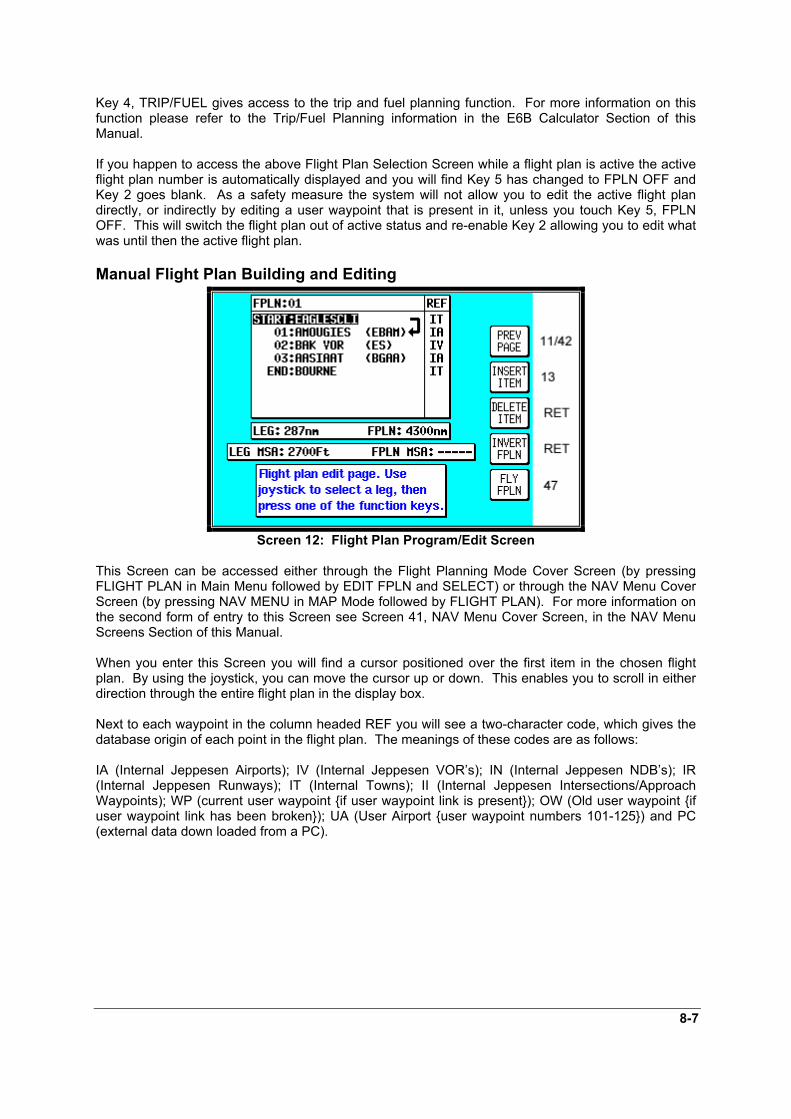
8-7
Key 4, TRIP/FUEL gives access to the trip and fuel planning function. For more information on thisfunction please refer to the Trip/Fuel Planning information in the E6B Calculator Section of thisManual.
If you happen to access the above Flight Plan Selection Screen while a flight plan is active the activeflight plan number is automatically displayed and you will find Key 5 has changed to FPLN OFF andKey 2 goes blank. As a safety measure the system will not allow you to edit the active flight plandirectly, or indirectly by editing a user waypoint that is present in it, unless you touch Key 5, FPLNOFF. This will switch the flight plan out of active status and re-enable Key 2 allowing you to edit whatwas until then the active flight plan.
Manual Flight Plan Building and Editing
Screen 12: Flight Plan Program/Edit Screen
This Screen can be accessed either through the Flight Planning Mode Cover Screen (by pressingFLIGHT PLAN in Main Menu followed by EDIT FPLN and SELECT) or through the NAV Menu CoverScreen (by pressing NAV MENU in MAP Mode followed by FLIGHT PLAN). For more information onthe second form of entry to this Screen see Screen 41, NAV Menu Cover Screen, in the NAV MenuScreens Section of this Manual.
When you enter this Screen you will find a cursor positioned over the first item in the chosen flightplan. By using the joystick, you can move the cursor up or down. This enables you to scroll in eitherdirection through the entire flight plan in the display box.
Next to each waypoint in the column headed REF you will see a two-character code, which gives thedatabase origin of each point in the flight plan. The meanings of these codes are as follows:
IA (Internal Jeppesen Airports); IV (Internal Jeppesen VOR’s); IN (Internal Jeppesen NDB’s); IR(Internal Jeppesen Runways); IT (Internal Towns); II (Internal Jeppesen Intersections/ApproachWaypoints); WP (current user waypoint if user waypoint link is present); OW (Old user waypoint ifuser waypoint link has been broken); UA (User Airport user waypoint numbers 101-125) and PC(external data down loaded from a PC).

8-8
In the example shown in the illustration for Screen 12, moving the joystick down would move thecursor down over 01 (or Waypoint 1) but would leave the “LEG” arrow positioned as it was. Thedistance shown next to the word LEG also would remain unchanged, showing the leg distance fromthe flight plan start point to Waypoint 01 (01). Moving the joystick down again would move the cursordown to 02, move the leg arrow down so that it is pointing between 01 and 02 and the figures next tothe word LEG would then show the distance from 01 to 02 and so on. The number next to the wordFPLN is the total flight plan length from start to finish.
In addition, as the cursor is moved up and down the flight plan, the MSA for that leg is shown in a boxbelow the LEG and FPLN info box as [LEG MSA: XXXX]. This value is the highest Grid MORA foundalong a ten mile wide corridor (including five miles past the waypoint) centred along each leg. Also shownis the [FPLN MSA: XXXX], which is the highest value leg MSA for the entire flight plan.
An extra waypoint can be inserted at any place in the flight plan (assuming the flight plan is not full).To do this, you position the cursor over the appropriate point in the flight plan and press Key 2,INSERT ITEM. For example, if you placed the cursor over 02, the new item would become 02 andthe existing 02 would become 03, etc. In a similar manner items may be deleted from the flight planby positioning the cursor and pressing Key 3, DELETE ITEM. Key 4 inverts or reverses the flightplan. Key 5, FLY FPLN, throws the unit into Map Mode (Screen 47) with the selected flight planactive.
Manually Inserting a Waypoint into a Flight Plan and Manual DIRECT TOA Waypoint can be inserted into a flight plan by using a two step process, which is started by pressingKey 2, INSERT ITEM. The same process is followed when Key 5, DIRECT TO is selected in Screen38, MAP Mode when the joystick is not active.
Step 1. Selecting data source
Screen 13: Database Selection Screen
This Screen shows a list of data libraries and you will find a cursor positioned over the wordAIRPORTS. You can use the joystick to move the cursor up and down the list of databases. Keys 3,4and 5 only appear if this Screen is called from Screen 38, MAP Mode as a DIRECT TO.
By moving the cursor you select the database that contains the item you are looking for, whether toinsert into your flight plan or to use as a DIRECT TO destination. Once you have the cursor over thecorrect database, pressing Key 2, SELECT, will move you onto the next selection process, which isScreen 16, Item Selection.
As stated above, Key 3, NEAR APTS and Key 4, NEAR NAVAID, only appear if this Screen has beenentered after performing a DIRECT TO in Screen 38, Map Mode. For more information on thefunction of these keys, please refer to the Ten Nearest under the NAV Menu Screens Section in thisManual.
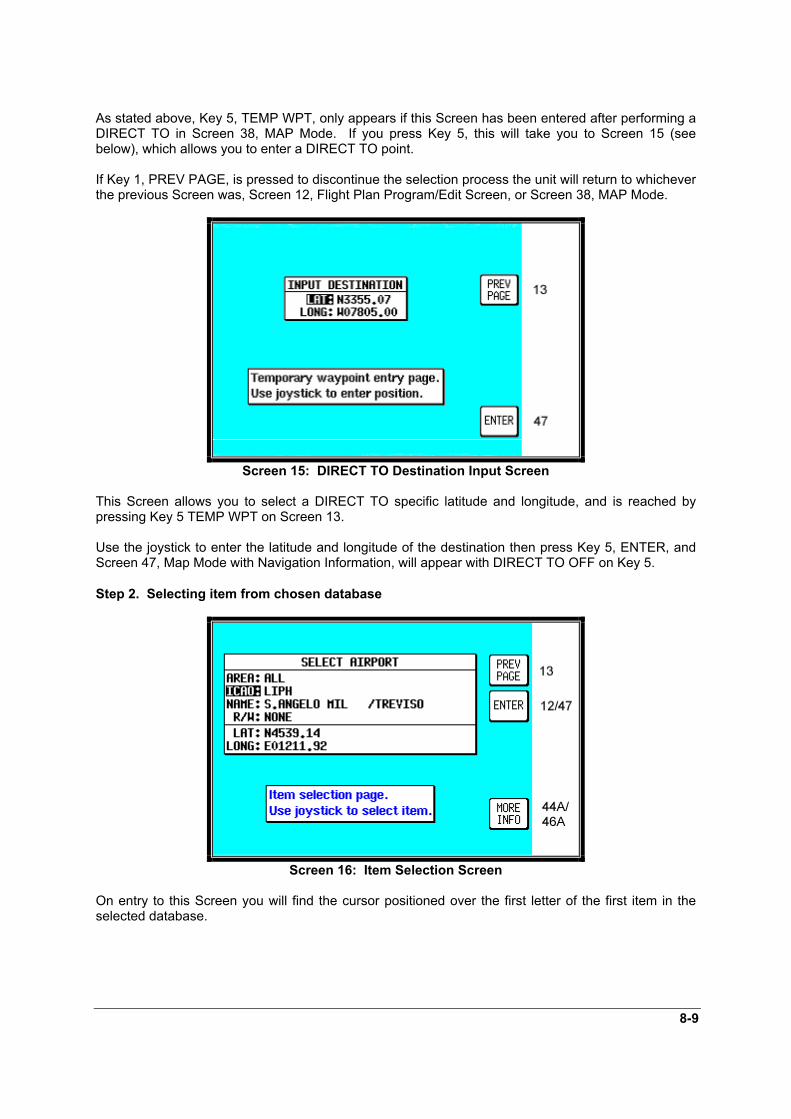
8-9
As stated above, Key 5, TEMP WPT, only appears if this Screen has been entered after performing aDIRECT TO in Screen 38, MAP Mode. If you press Key 5, this will take you to Screen 15 (seebelow), which allows you to enter a DIRECT TO point.
If Key 1, PREV PAGE, is pressed to discontinue the selection process the unit will return to whicheverthe previous Screen was, Screen 12, Flight Plan Program/Edit Screen, or Screen 38, MAP Mode.
Screen 15: DIRECT TO Destination Input Screen
This Screen allows you to select a DIRECT TO specific latitude and longitude, and is reached bypressing Key 5 TEMP WPT on Screen 13.
Use the joystick to enter the latitude and longitude of the destination then press Key 5, ENTER, andScreen 47, Map Mode with Navigation Information, will appear with DIRECT TO OFF on Key 5.
Step 2. Selecting item from chosen database
Screen 16: Item Selection Screen
On entry to this Screen you will find the cursor positioned over the first letter of the first item in theselected database.
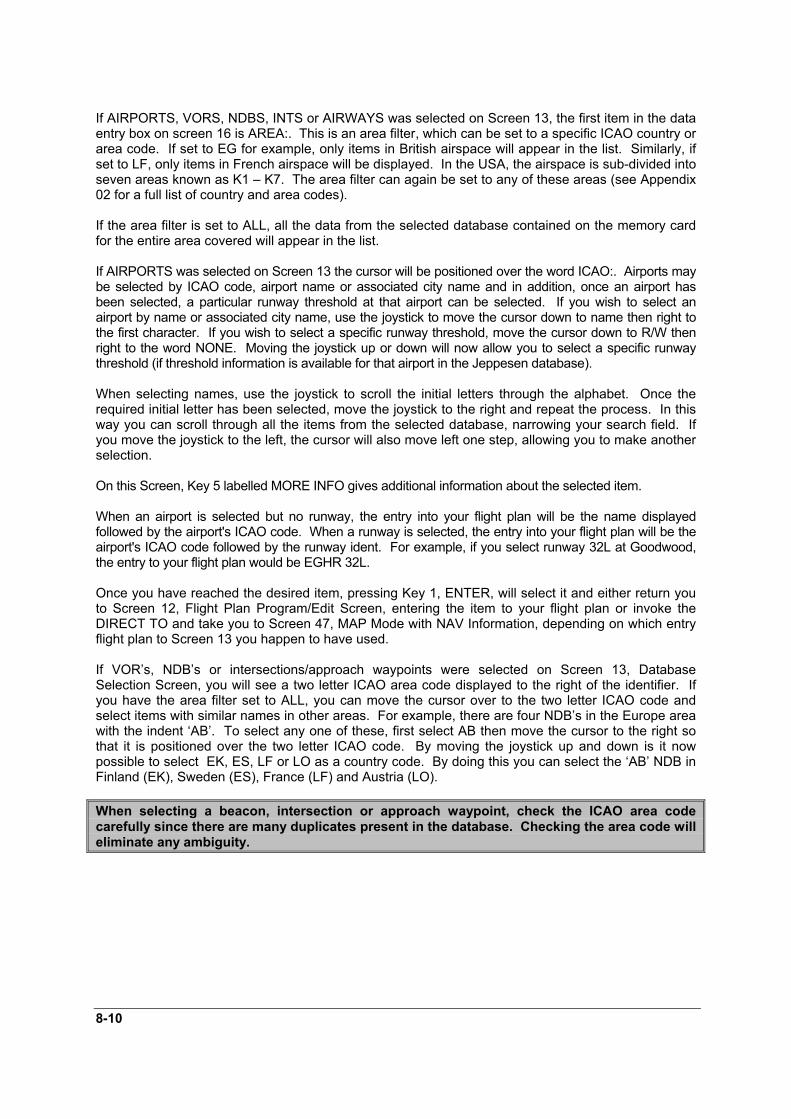
8-10
If AIRPORTS, VORS, NDBS, INTS or AIRWAYS was selected on Screen 13, the first item in the dataentry box on screen 16 is AREA:. This is an area filter, which can be set to a specific ICAO country orarea code. If set to EG for example, only items in British airspace will appear in the list. Similarly, ifset to LF, only items in French airspace will be displayed. In the USA, the airspace is sub-divided intoseven areas known as K1 – K7. The area filter can again be set to any of these areas (see Appendix02 for a full list of country and area codes).
If the area filter is set to ALL, all the data from the selected database contained on the memory cardfor the entire area covered will appear in the list.
If AIRPORTS was selected on Screen 13 the cursor will be positioned over the word ICAO:. Airports maybe selected by ICAO code, airport name or associated city name and in addition, once an airport hasbeen selected, a particular runway threshold at that airport can be selected. If you wish to select anairport by name or associated city name, use the joystick to move the cursor down to name then right tothe first character. If you wish to select a specific runway threshold, move the cursor down to R/W thenright to the word NONE. Moving the joystick up or down will now allow you to select a specific runwaythreshold (if threshold information is available for that airport in the Jeppesen database).
When selecting names, use the joystick to scroll the initial letters through the alphabet. Once therequired initial letter has been selected, move the joystick to the right and repeat the process. In thisway you can scroll through all the items from the selected database, narrowing your search field. Ifyou move the joystick to the left, the cursor will also move left one step, allowing you to make anotherselection.
On this Screen, Key 5 labelled MORE INFO gives additional information about the selected item.
When an airport is selected but no runway, the entry into your flight plan will be the name displayedfollowed by the airport's ICAO code. When a runway is selected, the entry into your flight plan will be theairport's ICAO code followed by the runway ident. For example, if you select runway 32L at Goodwood,the entry to your flight plan would be EGHR 32L.
Once you have reached the desired item, pressing Key 1, ENTER, will select it and either return youto Screen 12, Flight Plan Program/Edit Screen, entering the item to your flight plan or invoke theDIRECT TO and take you to Screen 47, MAP Mode with NAV Information, depending on which entryflight plan to Screen 13 you happen to have used.
If VOR’s, NDB’s or intersections/approach waypoints were selected on Screen 13, DatabaseSelection Screen, you will see a two letter ICAO area code displayed to the right of the identifier. Ifyou have the area filter set to ALL, you can move the cursor over to the two letter ICAO code andselect items with similar names in other areas. For example, there are four NDB’s in the Europe areawith the indent ‘AB’. To select any one of these, first select AB then move the cursor to the right sothat it is positioned over the two letter ICAO code. By moving the joystick up and down is it nowpossible to select EK, ES, LF or LO as a country code. By doing this you can select the ‘AB’ NDB inFinland (EK), Sweden (ES), France (LF) and Austria (LO).
When selecting a beacon, intersection or approach waypoint, check the ICAO area codecarefully since there are many duplicates present in the database. Checking the area code willeliminate any ambiguity.

8-11
Graphical Viewing and Editing of Flight Plans
Screen 19: View and Edit Flight Plans On Map Screen
This Screen is accessed by pressing FLIGHT PLAN in Main Menu, followed by EDIT FPLN and Key5, View Map, on Screen 11, Flight Plan Selection Screen. Screen 19 is displayed showing thestarting point of the selected flight plan centred in the middle of the display. The legs and waypointsare shown as in the illustration above.
The joystick can be used to move the pointer. The screen window can be moved around the map by“bumping” the screen borders left, right, up or down with the pointer. Distance and bearing boxesbelow the map show distance and bearing from the last user waypoint in the flight plan to thepointer. This feature allows you to enter waypoints as a distance and bearing from the previous flightplan point.
To build a flight plan you simply point at the first item to be included in the flight plan and press Key 2,ADD WPT (or ADD WayPoinT). This will place an S (for Start) next to the waypoint. If no suitabledata point or user waypoint is available beneath the pointer, a new user waypoint will be created;which can be given a name later by using Screen 9, Manual User Waypoint Edit Screen.
Now move the pointer to the second item in the flight plan and press Key 2, ADD WPT. This willplace an E (for End) next to the waypoint. To systematically create additional legs, draw a line fromthe waypoint marked (E), with the pointer, to the next waypoint and press ADD WPT again. You willnotice that the last point in the flight plan will always be labelled (E). Once you have finished buildingthe flight plan press PREV PAGE, this will detach the pointer from the flight plan. Press PREV PAGEagain to return to screen entered from, saving any changes made.
If you wish to add a new waypoint to a flight plan which you have stopped building (which is also thecase if you are editing an existing flight plan), whether it is at the start, the end or the middle of theflight plan, you will need to highlight the appropriate point (i.e.: either the start waypoint (S), the endwaypoint (E) or the leg line in which you wish to add a new waypoint). As soon as you do this, theADD WPT or GRAB LINE key will appear. Press the ADD WPT or GRAB LINE key to join the pointerback to the flight plan line and then move it to the new waypoint (NOTE: key 2 reverts to ADD WPT atthis point). Once over the new waypoint press ADD WPT to insert it, otherwise press PREV PAGE tocancel this action. Pressing Key 1 PREV PAGE again, returns to the screen entered from, saving anychanges made.

8-12
If, for example you wanted to add DEAL into the existing flight plan going from MANSTON to DOVERVOR shown in the illustration above, you would first position the pointer over the track line betweenManston and Dover VOR, thereby highlighting it and then press Key 2, GRAB LINE. This will pick upthe line. You would then move the pointer, stretching the track line like a rubber band, until it wasover DEAL and press Key 2, ADD WPT.. The new track line would then be set joining MANSTON toDEAL to DOVER VOR and the numbers shown next to DOVER VOR and all subsequent waypointswould be increased by one. DEAL would become 01, DOVER VOR 02 etc.
If, for example you wanted to add HERNE BAY to the end of the flight plan illustrated above, simplymove the pointer over MANSTON, thereby highlighting it and then press Key 2, ADD WPT. This willdraw a line from Manston to the pointer. Next move the pointer until it is over HERNE BAY, highlightit and press Key 2, ADD WPT again.
To delete a waypoint from a flight plan, point at the item you wish to remove and press Key 5,DELETE WPT. To delete a newly created user waypoint, you have to return to Screen 9, ManualUser waypoint Edit Screen, or 10, View and Edit User waypoints on the Map Screen. You can createuser waypoints on Screen 19 but not delete them from there.

9-1
9 MAP MODE SCREENS
Screen 38: Basic Map Mode Screen
This Screen can be accessed by pressing MAP mode in Main Menu. When you enter this Screen, ifthe Skymap IIIC's internal GPS receiver has been able to establish a fix or if the external GPS you areusing to feed your Tracker IIIC is sending valid data, a Screen similar to the above will be displayed.The map is initially displayed at the Zoom Level where the Scale Bar represents 8nm. This isapproximately the same scale as a 1:500,000 chart. If there is no valid GPS fix data available, thewords NO FIX POSSIBLE will be shown across the centre of the screen in a box. If the fix is lost atany time during normal operation of the unit, the same NO FIX POSSIBLE box will be overlaid on themap. For an External GPS source the additional messages NO EXTERNAL POSITION DATA andINVALID EXTERNAL POSITION DATA may be displayed in place of NO FIX POSSIBLE.
The map will be shown in either North Up mode or Track Up mode depending upon the setting youhave made from Screen 22, Map Customisation Screen. The displayed data will be updated everysecond. From this page, if you press Key 1, Screen 2 Main Menu will take its place. You can useKeys 2 and 3 at any time to zoom the map in and out to whichever one of the twelve pre-set scalesyou wish to use. The levels of detail appearing at each zoom level can be selected on Screen 22A/Bor C, described in the Setup Screens Section of this Manual. If you want to zoom in or out by morethan one step at a time, you can apply multiple presses to Keys 2, ZOOM IN, and 3, ZOOM OUT,whilst watching the scale bar calibration figure and the ZOOMING message box.
The small boxes marked TRK: and GS: display your present track and ground speed. Ground speedis displayed in the units selected on Screen 22, Map Customisation Screen. Track will be magnetic(i.e.: true with local variation automatically taken into account).
The box marked POS: will display your present position as a distance and cardinal bearing from thenearest item in the database. The geographical item used to describe your position to you is chosenon the basis of the POSITION REF: setting on Screen 22, Map Customisation Screen.
If you have chosen VOR’s as the position reference on Screen 22, your position will be reported as adistance (range) and bearing from the nearest VOR. If you have chosen VOR’s & AIRPORTS as theposition reference on Screen 22 and your position is within 5nm of a VOR, your position will bereported as a distance and bearing from that VOR even if there is an airport nearer (i.e. VOR’s havepriority). If there is no VOR within 5nm then your position will be reported with respect to the nearestVOR or airport with no priority being given for either.
If you have chosen ALL DATA as the position reference on Screen 22, your position will be reportedagainst a table of priorities. If your position is within five miles of an airport, it is your distance andbearing from that airport that will be displayed, even if there is a beacon, user waypoint or townnearer. All airport names are shown preceded by an asterisk character (*) in order to

9-2
distinguish them from towns or cities with similar names, which may have significantlydifferent locations. If your position is found to be within five miles of a VOR beacon and more thanfive miles from an airport, then your position will be shown with respect to the VOR beacon, even ifthere is a user waypoint, NDB or town nearer. User waypoints have next priority followed by NDB’sand towns last.
At the bottom left hand corner of the display you will also see a Scale Bar showing a measurement. The measurement may be in nautical miles, statute miles or kilometres depending on the map units,which you have selected from Screen 22, Map Customisation Screen.
Pressing Key 4 will take you to Screen 41, the NAV Menu Cover Screen. Pressing Key 5 will take youto Screen 13 from which you can select a DIRECT TO destination.
Under normal circumstances, you will not see any joystick pointer on Screen 38. However, if you domove the joystick, a pointer will appear just beside your present position icon and the display willchange to Screen 39 below.
Data Interrogation and Graphical DIRECT TO
Screen 39: Map Mode with Joystick Active Screen
As soon as you move the joystick while in Screen 38, Map Mode, a Screen similar to the aboveScreen 39 will be displayed. The map freezes in its present position with respect to the joystickpointer and the aircraft symbol indicating your present position starts to move across the Screen. Aline appears between present position and the joystick pointer. (The reason the map is made to stopmoving is that this makes accurate positioning of the joystick pointer much easier for you.)
Simultaneously, you will see the TRK and GS boxes have now changed to PDIS, PBRG and PETE(where P indicates Pointer). These now show the distance and bearing from present position to thejoystick pointer and the pointer estimated time en-route (PETE). The PETE is calculated on presentGS and would read 00:00 if you were stationary. You can use this function to measure distance,bearing and estimated time en-route to any point on the map. The window formed by the extremitiesof the Screen can be moved around the map by “bumping” the Screen borders left, right, up or downwith the pointer. A PANNING message will be displayed when a border has been bumped in thismanner, while the map screen is redrawn. You can still use Keys 2, ZOOM IN, and 3, ZOOM OUT, tozoom the map in and out. When you are finished using this Screen press Key 1, RESET STICK, andthe joystick pointer will vanish, your display will return to Screen 38 and the map will be placed backin its present position at the zoom level it was at prior to activating the joystick. If you don't move thejoystick for 30 seconds, this will have the same effect as pressing Key 1.
In addition to finding it useful for measuring distances, bearings and ETE's, you can utilise this Screenfor other tasks. If you place the pointer over any data icon and then press Key 4, MORE INFO,Screen 40 (Airport), Screen 40A (Beacon) or Screen 40C (all other data icons) as illustrated belowwill appear. These Screens contain additional data and information on the selected item.

9-3
If you want to navigate directly to any position, press Key 5 and you will obtain a DIRECT TO, takingyou to wherever the pointer is positioned, even if it is not pointing to a database item (NOTE: In thiscase the waypoint will be shown as ‘TEMP WPT’). This is a very useful feature for arbitrary in-flightdiversions. After you have pressed Key 5, DIRECT TO, Screen 47, Map Mode with NAV Info,appears, with Key 5 now labelled “DIRECT TO OFF”.
Airport Information
Screen 40: Map Mode Airport Info Screen
As explained above, you can access this Screen from Screen 39 by placing the joystick pointer overan airport icon and pressing Key 4, MORE INFO. All the information given here is derived from thebuilt-in Jeppesen database. Runway surfaces are shown as an H for hard and an S for soft. Lightingis shown as an L for lit and a U for unlit.
To obtain the goto for the chosen airport all you have to do is press Key 5, labelled DIRECT TO. Toreturn to the Map of Screen 39 you should press Key 1, PREV PAGE. Alternatively, the unit gives you30 seconds to read what you require from the Info Screen and then automatically returns to Screen39.
Pressing Key 5, DIRECT TO, in MAP Mode when the joystick is not active, can also access thisScreen. Allowing you to call up the item of interest from the airports database as if you were selectingit for a DIRECT TO.

9-4
Beacon Information
Screen 40A: Map Mode Beacon Information Screen
As explained above, you can access this Screen from Screen 39 by placing the joystick pointer over aVOR or NDB icon and pressing Key 4, MORE INFO. Full details of the Beacon are listed, type,frequency and ident. The fourth line in the box is a visual representation of the Morse ident and if youare one of those pilots whose knowledge of Morse is less than perfect, all you have to do is press Key2, IDENT. The unit will bleep out the correct ident (on its internal bleeper and on the external alarm, ifthis is switched on). You can then compare this to the ident you are hearing over the radio to verifythat you are indeed tuned to the beacon you want.
To obtain a goto for the chosen Beacon (VOR or NDB) all you have to do is press Key 5, labelledDIRECT TO. To return to the Map of Screen 39 you should press Key 1, PREV PAGE. Alternatively,the unit gives you 30 seconds to read what you require and then automatically returns to Screen 39.
Pressing Key 5, DIRECT TO, in Map Mode when the joystick is not active, can also access thisScreen. Allowing you to call up the item of interest from the either the VOR’s or NDB’s database as ifyou were selecting it for a DIRECT TO.

9-5
General Icon Information
Screen 40C: Map Mode General Information Screen
As explained above, you can access this Screen from Screen 39 by placing the joystick pointer overany data icon that is not an airport, VOR or NDB and pressing Key 4, MORE INFO. All availableinformation concerning the chosen data item is then listed.
To obtain a goto for the chosen item all you have to do is press Key 5, labelled DIRECT TO. Toreturn to the Map of Screen 39 you should press Key 1, PREV PAGE. Alternatively, the unit givesyou 30 seconds to read what you require and then automatically returns to Screen 39.

9-6
Airspace InterrogationIn order to interrogate a piece of airspace in MAP Mode, move the joystick operated pointer and point atone of the airspace boundaries. After you have released the joystick, the software will search theairspace database and after a short time will re-draw the piece of airspace to which you have pointed in abolder line. IMPORTANT: When a single airspace boundary line is shared by two different pieces ofairspace (which is very common), the airspace with the lower vertical limit will always be highlighted.
Once you are sure the piece of airspace highlighted is the piece you want information on (you may haveto zoom out to verify this, but beware, some airspace switches off as you zoom out dependant on thesettings made in Screen 22C, Airspace Data Class Setup Screen), press MORE INFO key and Screen40B, Airspace Information Screen, will be displayed.
Screen 40B: Airspace Information Screen
The information shown on this screen is all the information from the internal Jeppesen database that isrelevant to the airspace you have selected. If some of the fields are blank or say SEE CHART, thismeans that Jeppesen data is not available for that particular item.

10-1
10 NAV MENU SCREENS
Screen 41: NAV Menu Cover Screen
You can enter this important Screen by pressing Key 4, NAV MENU, while in MAP Mode (on Screen38 or 47). It is a versatile Screen with several useful functions.
If you move the joystick up or down when in this Screen, the screen layout presented when in MapMode with NAV Information (or NAV Mode i.e. flying a flight plan or a DIRECT TO) can be selected tobe one of the following
TOPO ON: Large map, full colour cartography, and small NAV information text.TOPO ON, LRG TXT: Large map, full colour cartography, and large NAV information text. This willrevert to the TOPO ON large map when the joystick is hit.TOPO ON, CDI: Pseudo HSI style display, which reverts to TOPO ON large map when joystick is hit.TOPO OFF: Large map, black background, no cartography, and Jeppesen data only, small NAVinformation text.TOPO OFF, LRG TXT: Large map, black background, no cartography, and Jeppesen data only, largeNAV information text. This will revert to the TOPO OFF large map when the joystick is hit.TOPO OFF, CDI: Pseudo HSI style display, which reverts to TOPO OFF large map when joystick ishit.
Please refer to the Map Setup Screens in the Setup Screens Section of this Manual for furtherinformation regarding data settings for each mode.
If you wish to return to your previous Map Mode Screen at any time, press Key 1, MAP.
Key 2, FLIGHT PLAN, gives you direct access to Flight Planning Mode where you can manuallyselect, cancel and edit flight plans as required.
If you press Key 3, NEAR APTS, you will be presented with Screen 43, Ten Nearest Airports Screen,on which you can read off the ten airports nearest to your present position.
If you press Key 4, NEAR NAVAID, you will see Screen 45, Ten Nearest Beacons Screen, giving youdetails of the ten VOR’s and NDB’s nearest to you. For more information on Screens 43 and 45 referto the Ten Nearest later on in this Section of the Manual. When a DIRECT TO is active, Key 4 willread CENTER CDI which centres the CDI. The NEAR NAVAID function will still be available via theNEAR APTS function.
If you wish to save your present position, press Key 5, SAVE WPT, and your co-ordinates will besaved as the next available user waypoint number. Once the user waypoint has been saved, the

10-2
Screen will revert to Map Mode (Screen 38 or 47) where the new user waypoint will already featureon the map.
The text boxes in the bottom half of the screen gives the following information:
NAV Mode selected (one of six options described above)Position in plain EnglishPosition in latitude/longitude (or the co-ordinate system selected on the Map Setup Screen)Track and Ground SpeedGPS AltitudeMSA for the present position
The MSA box displays the highest Grid MORA value within a ten mile radius of your present position at alltimes. See Appendix 02 for a more detailed explanation of Grid MORA.
WARNING: The MSA altitudes displayed are advisory in nature only. They should not berelied upon as the sole source of obstacle and terrain avoidance information. Always refer tocurrent aeronautical charts for appropriate minimum clearance altitudes.
Selecting a Flight Plan
Screen 42: Flight Plan Selection Screen
Pressing Key 2, FLIGHT PLAN, on Screen 41, NAV Menu Cover Screen, enters this Screen. Onentry to this Screen you will see a cursor positioned over Flight Plan Number 01, or if there is a flightplan already active, its number will be shown instead of the Flight plan last touched. You will see thefirst few items of the selected flight plan together with its final destination in the box under the FlightPlan Number. You can select any flight plan you want by using the joystick to scroll the flight plannumber up or down. You are free to select any one of the 99 available flight plans. If you wish toreturn to the NAV Menu Cover Screen (Screen 41) press the PREV PAGE Key 1.
If the selected flight plan is already running, Key 5 will read FPLN OFF. If there is no active flight plan, Key5 will be blank and Key 2 will read SELECT. Pressing Key 2 will call Screen 12, Flight PlanProgram/Edit Screen for the selected flight plan. An active flight plan can be switched off at any time bypressing Key 5, FPLN OFF.
Pressing Key 5 will cancel the active flight plan and allow you to gain access to what was the active flightplan. (In the interests of safety, the software has been designed not to permit you to edit and fly a flightplan at the same time.)
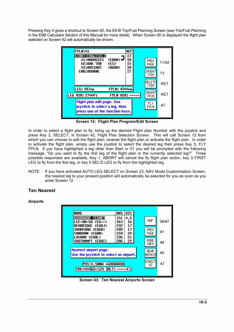
10-3
Pressing Key 4 gives a shortcut to Screen 60, the E6-B Trip/Fuel Planning Screen (see Trip/Fuel Planningin the E6B Calculator Section of this Manual for more detail). When Screen 60 is displayed the flight planselected on Screen 42 will automatically be shown.
Screen 12: Flight Plan Program/Edit Screen
In order to select a flight plan to fly, bring up the desired Flight plan Number with the joystick andpress Key 2, SELECT, in Screen 42, Flight Plan Selection Screen. This will call Screen 12 fromwhich you can choose to edit the flight plan, reverse the flight plan or activate the flight plan. In orderto activate the flight plan, simply use the joystick to select the desired leg then press Key 5, FLYFPLN. If you have highlighted a leg other than Start or 01 you will be prompted with the followingmessage, “Do you want to fly the first leg of the flight plan or the currently selected leg?” Threepossible responses are available, Key 1, ABORT will cancel the fly flight plan action, key 3 FIRSTLEG to fly from the first leg, or key 5 SEL’D LEG to fly from the highlighted leg.
NOTE: If you have activated AUTO LEG SELECT on Screen 23, NAV Mode Customisation Screen,the nearest leg to your present position will automatically be selected for you as soon as youenter Screen 12.
Ten Nearest
Airports
Screen 43: Ten Nearest Airports Screen

10-4
This Screen is accessed by pressing Key 3, NEAR APTS, on Screen 41, NAV Menu Cover Screen,and dynamically shows the range and bearing of the ten nearest airports. When this Screen appearsyou will find a cursor over the first airport in the list.
You can scroll up and down the list by using the joystick. Once the cursor is lying over the name ofthe airport you require, if you press Key 3, MORE INFO, Screen 44 below will appear, giving youadditional information about that airport.
To obtain a DIRECT TO for the chosen airport all you have to do is press Key 5, labelled DIRECT TO,and you will switch back to (Screen 47) MAP mode with the selected DIRECT TO activated.
Key 1, MAP, returns you to MAP Mode, Screen 38 or 47. Key 2 returns you to the NAV Menu CoverScreen (Screen 41). By pressing Key 4, NEAR NAVAID, you can switch to Screen 45, Ten NearestBeacons, giving information about the ten nearest beacons.
Screen 44: Airport Information Screen
Once you have selected an airport on Screen 43 and pressed Key 3, MORE INFO, the display willchange to Screen 44 above. This gives additional information about runways, frequencies, elevationetc. for the airport in question.
To return from this Screen to Map Mode (Screen 38 or 47) you simply press Key 2. To select anotherairport from the Ten Nearest (Screen 43) you press Key 1 and if you want to see the list of tennearest beacons, simply press Key 3, which will take you directly to Screen 45, Ten NearestBeacons. To obtain a DIRECT TO for the chosen airport all you have to do is press Key 5, labelledDIRECT TO, and you will switch back to (Screen 47) MAP Mode with the selected DIRECT TOactivated.
If you want to view the area immediately around the chosen airport, press Key 4. This will call Screen10A which is very similar to Screen 10, the View and Edit User Waypoint on the Map Screen. Screen10A will revert back to screen 44 after 30 seconds with no key or joystick activity or can be cancelledby pressing Key 1, PREV PAGE.

10-5
Beacons
Screen 45: Ten Nearest Beacons Screen
This Screen is accessed by pressing Key 4, NEAR NAVAID, on Screen 41, NAV Menu Cover Screen,and dynamically shows the range and bearing of the ten nearest beacons. When this Screenappears you will find a cursor placed over the first beacon in the list. The list can be scrolled up anddown using the joystick. Once you have placed the cursor over the name of the beacon you want,press Key 3, MORE INFO, to display Screen 46 below, which gives additional information about thatbeacon.
Pressing Key 1 will return you to MAP mode (Screen 38 or 47). Key 2 returns you to Screen 41, NAVMenu Cover Screen. Pressing Key 4, NEAR APTS, will take you to Screen 43, giving you the list ofthe ten nearest airports.
To obtain a DIRECT TO for the chosen beacon all you have to do is press Key 5, labelled DIRECTTO, and you will switch back to (Screen 47) MAP mode with the selected DIRECT TO activated.
Screen 46: Beacon Information Screen
The Screen above shows the additional information about the beacon chosen on Screen 45, TenNearest Beacons.

10-6
From here by pressing Key 2 you will get back to MAP mode (Screen 38 or 47). To select anotherbeacon from the Ten Nearest (Screen 45) you press Key 1. If you press Key 3, IDENT, the unit willmimic the Morse code ident for the chosen beacon on the internal beeper (and on the external alarmif you switched this on in Screen 23, NAV Mode Customisation Screen).
If you want to view the area immediately around the chosen beacon, press Key 4. This will callScreen 10A which is very similar to screen 10, the View and Edit User Waypoint on the Map Screen. Screen 10A will revert back to screen 46 after 30 seconds with no key or joystick activity or can becancelled by pressing Key 1, PREV PAGE.
To obtain a DIRECT TO for the chosen beacon all you have to do is press Key 5, labelled DIRECTTO, and you will switch back to (Screen 47) MAP mode with the selected DIRECT TO activated.

11-1
11 MAP MODE WITH NAV INFORMATIONWhenever a flight plan is active or you have called for a DIRECT TO, the map will have extra navigationinformation added to it and will resemble Screen 47 below. Alternatively you may have selected one ofthe other Navigation Modes detailed in the NAV Menu Screens Section of this Manual. The samenavigation data is presented on all the alternative screens in different ways. The following text refers tothe standard Navigation Mode Screen setting (TOPO ON). Alternative Screens 47A and 47B arediscussed at the end of this section.
Screen 47: Map Mode with NAV Information Screen
If the TOPO OFF Large Map Mode is selected, the map will display aeronautical data only on a blackbackground.
The Course Deviation Indicator (CDI) at the bottom right of the map can be switched ON or OFF or beset to work numerically and the Full Scale Deflection (FSD) selected on Screen 23, NAV ModeCustomisation Screen. If you have selected the CDI alarm ON, when the last element of the CDI bargraph comes on (or when the full scale value as set on Screen 23 is reached) the internal andexternal alarms (if switched on) will beep at a rate of 2Hz for 5 seconds.
Key 5 will change to ALARM OFF and if you press this before the 5 seconds are up this will silencethe alarm. When the alarm switches off automatically after 5 seconds, Key 5's label will go blank andhave no function for 2 seconds then revert to DIRECT TO (or DIRECT TO OFF). This is to make sureyou don't inadvertently select or cancel DIRECT TO mode if you press this Key just as it is cancellingautomatically. The CDI alarm resets itself as soon as you come back within the full scale set. It willthen be reactivated whenever the full scale is exceeded again.
The box at the bottom right of the map window shows the destination point when you are in DIRECTTO Mode preceded by the “DIRECT TO” symbol or the FROM and TO waypoints when you are inFlight Plan Mode.
A great deal of other navigation information is available to you above and below the map. (Thepositioning of this data that is described in the following relates to when the screen is in LandscapeMode. The position of some of the items is different when Portrait Mode is used.) Starting at the top ofthe screen on the left hand side you will see DIS. This is the distance or range to run to thedestination point from your present position. This distance figure is given in whichever units youselected on Screen 22, Map Customisation Screen. In the left centre of the screen at the top you canread BRG. This is the magnetic heading to steer (assuming no wind) to the next turning point.

11-2
To the right of BRG at the top of the map is the ETE. This gives the Estimated Time En-route (i.e. theestimated time, in hours and minutes, or minutes and seconds if under 1 hour, that it will take you toget to the destination point from your present position assuming you maintain your present groundspeed.
On the Skymap IIIC unit only, at the top right of the map is the ETA. This is the Estimated Time ofArrival at the next turning point. Ensure you have set the local time offset correctly to get correctETA’s. Refer to the GPS Status Screens Section of this Manual for more details. (The reason thatETA is not available on Tracker IIIC is that, depending on the type of GPS receiver in use, real timeand local time offset is not always known.)
In the left centre of the screen at the bottom is TRK. This is the actual magnetic track the aircraft istravelling over the ground. By comparing this with your magnetic heading you can make an estimateof the crosswind component.
To the right of TRK is GS. This is the actual ground speed of the aircraft and is displayed in Knots ifyou set the map units to nautical miles on Screen 22, Map Customisation Screen, MPH if you setthem to statute miles or KPH if the map units are set to kilometres. By comparing the GS with yourTAS you can make an estimate of the head or tail wind component. Alternatively refer to Screen 58,Density Altitude, True Air Speed, and Winds Aloft Screen in the E6B Calculator Screens Section ofthis Manual.
If ground speed is less than 3 Kt., the map will revert to North Up even if Track Up is selected. This isto stop the map rotating when static due to the effects of SA (Selective Availability, see Appendix 03for further details of SA).
If you have entered this Screen 47 by activating a flight plan, a DIRECT TO can be performed on topof the flight plan. You can initiate the DIRECT TO either to an item from the database or by using thejoystick pointer or by calling up one of the 10 nearest airports or beacons. In each case Key 5's labelwill change to “DIRECT TO OFF”. The flight plan that previously was active will fall into thebackground and will be replaced by the DIRECT TO information. When the DIRECT TO destinationis reached or whenever you press the DIRECT TO OFF Key (Key 5), the flight plan and its informationwill be reinstated.
Viewing En-route ETA’s and Direct-To PageWhen flying a flight plan, the ETA’s for each leg of the flight plan can be viewed on Screen 41A which isaccessed by pressing Key 5, DIRECT TO on the MAP mode screen (screen 47).
Screen 41A: View ETA’s and Skip Leg Screen.
On entry to Screen 41A, a Magenta cursor will be placed over the current destination waypoint.
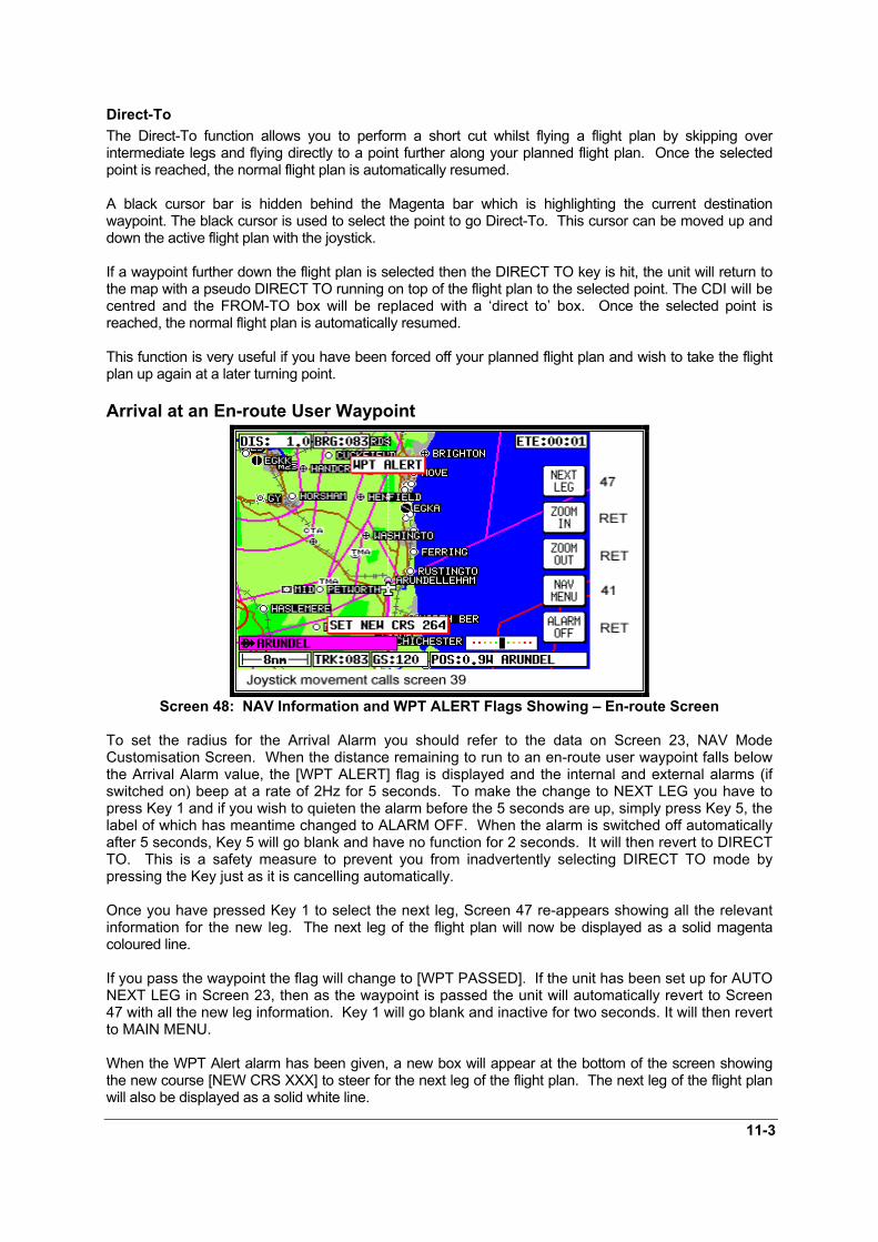
11-3
Direct-ToThe Direct-To function allows you to perform a short cut whilst flying a flight plan by skipping overintermediate legs and flying directly to a point further along your planned flight plan. Once the selectedpoint is reached, the normal flight plan is automatically resumed.
A black cursor bar is hidden behind the Magenta bar which is highlighting the current destinationwaypoint. The black cursor is used to select the point to go Direct-To. This cursor can be moved up anddown the active flight plan with the joystick.
If a waypoint further down the flight plan is selected then the DIRECT TO key is hit, the unit will return tothe map with a pseudo DIRECT TO running on top of the flight plan to the selected point. The CDI will becentred and the FROM-TO box will be replaced with a ‘direct to’ box. Once the selected point isreached, the normal flight plan is automatically resumed.
This function is very useful if you have been forced off your planned flight plan and wish to take the flightplan up again at a later turning point.
Arrival at an En-route User Waypoint
Screen 48: NAV Information and WPT ALERT Flags Showing – En-route Screen
To set the radius for the Arrival Alarm you should refer to the data on Screen 23, NAV ModeCustomisation Screen. When the distance remaining to run to an en-route user waypoint falls belowthe Arrival Alarm value, the [WPT ALERT] flag is displayed and the internal and external alarms (ifswitched on) beep at a rate of 2Hz for 5 seconds. To make the change to NEXT LEG you have topress Key 1 and if you wish to quieten the alarm before the 5 seconds are up, simply press Key 5, thelabel of which has meantime changed to ALARM OFF. When the alarm is switched off automaticallyafter 5 seconds, Key 5 will go blank and have no function for 2 seconds. It will then revert to DIRECTTO. This is a safety measure to prevent you from inadvertently selecting DIRECT TO mode bypressing the Key just as it is cancelling automatically.
Once you have pressed Key 1 to select the next leg, Screen 47 re-appears showing all the relevantinformation for the new leg. The next leg of the flight plan will now be displayed as a solid magentacoloured line.
If you pass the waypoint the flag will change to [WPT PASSED]. If the unit has been set up for AUTONEXT LEG in Screen 23, then as the waypoint is passed the unit will automatically revert to Screen47 with all the new leg information. Key 1 will go blank and inactive for two seconds. It will then revertto MAIN MENU.
When the WPT Alert alarm has been given, a new box will appear at the bottom of the screen showingthe new course [NEW CRS XXX] to steer for the next leg of the flight plan. The next leg of the flight planwill also be displayed as a solid white line.

11-4
Prior to reaching a user waypoint within a flight plan, Turn Anticipation provides navigation along a curvedpath segment to ensure a smooth transition between two adjacent legs in the flight plan. The curved pathsegment is based upon the aircraft's groundspeed and the amount of course angle change between thelegs.
Turn Anticipation will only work if it is selected ON in Screen 23, NAV Mode Customisation Screen, and ifthe course change is greater than 5° and less than 90°. If the course change is less than 5° then turnanticipation is not necessary. If the course change is greater than 90° it is up to the pilot which way roundthe turning point he turns.
If Turn Anticipation is set to ON and the upcoming leg satisfies the Turn Anticipation rules (i.e. coursechange >5° or <90°), the Turn Anticipation function is activated. If Turn Anticipation is switched OFF orthe upcoming leg course change is >90°, you may get a STEEP TURN warning. The Steep Turn warningwill be given if the upcoming turn will involve a bank angle in excess of 25° based on current groundspeed.
Arrival at Your Final Destination
Screen 49: NAV Information and WPT ALERT Flags Showing - Final Screen
This Screen appears whenever the next user waypoint is the last in the current flight plan. When thedistance to run to the last WPT falls below the Arrival Alarm value, the [WPT ALERT] flag is shownand the internal and external alarms (if switched on) beep at a rate of 2Hz for 5 seconds.
The label for Key 1 changes to NAV OFF and that for Key 5 changes to ALARM OFF. If you pressKey 5 the audible alarm is silenced. The alarm will switch itself off automatically after 5 seconds, thenafter a further 2 seconds the label for Key 5 will revert to DIRECT TO (or DIRECT TO OFF if inDIRECT TO mode).
If you are in Flight plan Mode when Key 1 is pressed, the Navigation MAP Mode is cancelled andScreen 38 is called. If you are in DIRECT TO mode when Key 5 is pressed, DIRECT TO Mode iscancelled and Screen 38 will appear. If you are in DIRECT TO Mode with an underlying flight plan stillactive when you press Key 5, DIRECT TO Mode will be cancelled and Screen 47 will reappear withthe original flight plan reinstated.
As the last waypoint is passed, the flag will change to [WPT PASSED].
Alternative Navigation Map ModesYou may have selected one of the other Map presentation modes detailed in the NAV Menu ScreensSection of this Manual. The same navigation data as described previously is presented on all thealternative screens in different ways.

11-5
TOPO ON / TOPO OFF Large Text Mode
Screen 47A: TOPO ON Large Text NAV Information Screen.
This Screen presents the numeric navigation information in large text laid over the map display in such away as to allow you a forward view of the map if being used in Track Up Mode. As with standard LargeMap NAV Mode, the CDI scale and format may be adjusted. If the joystick is touched, the display willimmediately revert to Large Map format to allow full use of map graphics. When the joystick is reset orafter 30 seconds with no key or joystick activity, Screen 47A will be reinstated.
As with Large Map Mode, if the TOPO OFF Large Text Mode is selected, the map will displayaeronautical data only on a black background.
TOPO ON / TOPO OFF CDI (Pseudo HSI) Mode:
Screen 47B: CDI (Pseudo HSI) NAV Information Screen
This Screen presents numeric navigation information in small text but instead of a map display, shows apseudo CDI complete with OBS knob. The aircraft icon in the center of the CDI will remain static and theouter ring represents the desired magnetic track between the start waypoint and the destination waypoint(i.e. magnetic bearing to waypoint if you were on track). On entering NAV Mode or activating a new flightplan leg or a DIRECT TO, the outer ring will show the desired track to the active waypoint.
A GPS TRACK bug, which rotates with the aircraft’s actual track, is positioned on the CDI outer ring. Thisindicates the actual magnetic track of the aircraft. There is also included a conventional TO / FROM flag.
Flying with the pseudo CDI is very similar to flying with a conventional VOR indicator. Off track error(XTE) is represented by a bar that moves left or right of center. The center of the scale represents theaircraft's position. As with a conventional CDI or VOR indicator, to correct your track error, fly towards the

11-6
bar. The full scale deflection or scale of the CDI can be selected on Screen 23, NAV Mode CustomizationScreen.
In order to gain, and remain on the desired track, adjust your aircraft heading until the CDI bar is centered. Once the CDI bar is in the center of the display indicating no cross track error (XTE), adjust your aircraftheading in small increments until the track bug, which rotates around the outer ring, is at the top of thedisplay.
Once the CDI is centered and the track bug is aligned at the top of the display you are flying preciselyalong your desired track. If the track bug is aligned at the top of the display but the CDI bar is notcentered, this indicates you are flying parallel to your desired track by however far the XTE is indicating.
If whilst flying a flight plan you need skip to another waypoint in the flight plan, press key 5 (DIRECT TO)followed by key 3 (DIRECT TO) in exactly the same way as described earlier in this section.
The TO / FROM flag will normally point up to indicate you are flying TO the waypoint. When you passyour destination waypoint, the TO / FROM flag will point down to indicate you have passed the waypointand you are now flying away FROM your destination. As you pass your waypoint and the FROM flagappears, the desired track ring will remain fixed at the original desired track and the CDI will continue toshow track error left or right of the extended leg line.
If whilst en-route to a destination you decide that you would like to approach that destination point from anangle other than that displayed on the CDI by the desired track ring, you can alter the desired track settingby pushing the INC OBS (increment OBS) or DEC OBS (decrement OBS) Keys.
This has the effect of rotating your desired track ring and hence rotating the desired track line on the mapscreen using the destination point as a pivot. For example if you were approaching an airport from thesouth west on an inbound heading of 070° but the runway in use at that airport was 09, it may bedesirable to approach the airport on a heading of 090° so that you were lined up for the approach.
By pressing the INC OBS Key you would increment the desired track setting from 070° to 090°. The CDIwould then show a fly left indication because you would be off track to the right from your new track line. By turning left it would then be possible to intercept the new track line then fly straight into the airport onthe new approach heading.
If the joystick is touched, the display will immediately revert to Map format to allow full use of mapgraphics. When the joystick is reset, Screen 47B will be reinstated. When flying with the CDI selected,WPT ALERT messages and other warnings will be displayed in the CDI area.

12-1
12 DEMO MODETo allow you to practice all aspects of navigation on the ground and to become familiar with handlingit, your unit can be used as a simulator by selecting its fully functioning Demo Mode. Using this modeyou can also replay your logged flight data.
Screen 20: Demo Mode Setup Screen
This Demo Mode Screen can be accessed by pressing Key 3, DEMO MODE, on Screen 1, TitleScreen, provided that, since the time you switched it on, your Skymap IIIC has not received validsatellite information from its internal GPS receiver, or your Tracker IIIC similarly lacks fix data from itsexternal receiver.
When you enter Demo Mode you will find a cursor over the word LAT. You can then use the joystickto set up the latitude and longitude for any point from which you want the demo to start. (The defaultlatitude and longitude will be the co-ordinates of your last fix position.) Alternatively you can pressKey 3 and select a start point from the built in database. You can also set the airspeed at which youwant to fly the demo to anything between 000 and 999 Knots.
Once you have set your position and speed, if you press Key 5 you will find Screen 38, Map Mode,displayed and you are ready to start Demo Mode. All map Screens that you access whilst DemoMode is switched on will, for safety reasons, have a DEMO MODE warning box displayed to ensureyou do not use them while in the air.
If you wish to replay the flight data logged into your unit, set the airspeed as explained above then pressKey 4. Screen 50 will then be displayed with the logged data being replayed at the specified speed. Thisallows long flight plans to be replayed in fast motion.

12-2
Screen 50: Representation of Screen 47 Showing DEMO MODE Flag
If Demo Mode is active and you switch to Screen 2, Main Menu Screen, you will see Key 3 is nowlabelled DEMO OFF and can be used to cancel Demo Mode.

13-1
13 E6-B CALCULATORE6-B functions are accessible by pressing Key 3, NOTE PAD, in Main Menu followed by Key 3, E6-BCALC, in the Note Pad Screen. This gives access to Screen 57, E6-B Calculator Screen. This function isnot available in Demo Mode.
Screen 57: E6-B Calculator Cover Screen
Key 1 returns you to Screen 2 Main Menu.Key 2 calls Screen 58, the Density Altitude/TAS/Winds Aloft Calculator page.Key 3 calls Screen 59, Vertical Navigation page.Key 4 calls Screen 60, Trip/Fuel Planning page.Key 5 calls Screen 61, Sunset/Sunrise Calculator page.
Density Altitude/TAS/Winds Aloft Calculator
Screen 58: Density Altitude, True Air Speed & Winds Aloft Screen
On entry to this Screen a cursor will be positioned over the Indicated Altitude (IALT) data entry field.
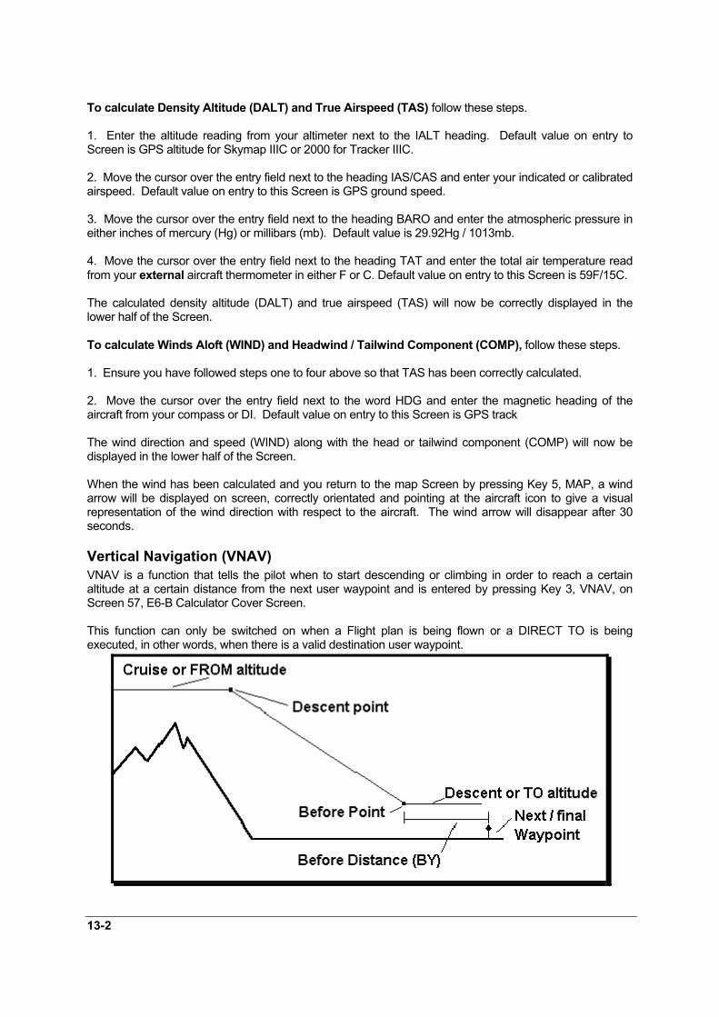
13-2
To calculate Density Altitude (DALT) and True Airspeed (TAS) follow these steps.
1. Enter the altitude reading from your altimeter next to the IALT heading. Default value on entry toScreen is GPS altitude for Skymap IIIC or 2000 for Tracker IIIC.
2. Move the cursor over the entry field next to the heading IAS/CAS and enter your indicated or calibratedairspeed. Default value on entry to this Screen is GPS ground speed.
3. Move the cursor over the entry field next to the heading BARO and enter the atmospheric pressure ineither inches of mercury (Hg) or millibars (mb). Default value is 29.92Hg / 1013mb.
4. Move the cursor over the entry field next to the heading TAT and enter the total air temperature readfrom your external aircraft thermometer in either F or C. Default value on entry to this Screen is 59F/15C.
The calculated density altitude (DALT) and true airspeed (TAS) will now be correctly displayed in thelower half of the Screen.
To calculate Winds Aloft (WIND) and Headwind / Tailwind Component (COMP), follow these steps.
1. Ensure you have followed steps one to four above so that TAS has been correctly calculated.
2. Move the cursor over the entry field next to the word HDG and enter the magnetic heading of theaircraft from your compass or DI. Default value on entry to this Screen is GPS track
The wind direction and speed (WIND) along with the head or tailwind component (COMP) will now bedisplayed in the lower half of the Screen.
When the wind has been calculated and you return to the map Screen by pressing Key 5, MAP, a windarrow will be displayed on screen, correctly orientated and pointing at the aircraft icon to give a visualrepresentation of the wind direction with respect to the aircraft. The wind arrow will disappear after 30seconds.
Vertical Navigation (VNAV)VNAV is a function that tells the pilot when to start descending or climbing in order to reach a certainaltitude at a certain distance from the next user waypoint and is entered by pressing Key 3, VNAV, onScreen 57, E6-B Calculator Cover Screen.
This function can only be switched on when a Flight plan is being flown or a DIRECT TO is beingexecuted, in other words, when there is a valid destination user waypoint.

13-3
Screen 59: V NAV Setup Screen
On entry to Screen 59, if there is no active user waypoint the DESTINATION box will read NO WPT. Youmust have an active user waypoint in order to activate VNAV Mode. If there is an active user waypoint thedestination user waypoint name will be shown.
Once in the VNAV Screen you must enter the cruise altitude (the altitude FROM which you will descend),the final altitude (the altitude TO which you want to descend), the rate of descent (in FPM feet per minute)and the distance before the upcoming user waypoint that you want to achieve the new level BY.
On entry to this Screen, the FROM value will default to GPS altitude if your unit is a Skymap IIIC or to5000 feet if your unit is a Tracker IIIC (or the last set value). The TO value will default to 1500 feet (or thelast set value). The BY value will default to 5.0nm (or last set value) and the AT value will default to500fpm (or last set value).
The DESCEND IN box will show an active countdown of the time left before you should start your descentand will be recalculated if you change any of the four variables (FROM, TO, BY or AT).
If Screen 59 is entered then exited by pressing Key 1, VNAV mode is not activated, the values are simplyretained for use later in the flight.
If Screen 59 is entered then exited by pressing Key 5, Screen 47, 47A or 47B (NAV Mode) Screen will bedisplayed with the following changes.
1. Key 5 will now read VNAV OFF and there is a new VNAV message box.
2. If the DESCEND IN counter is greater than 00:00, the new message box will show DESCEND IN withthe counter value.
3. When the DESCEND IN counter reaches 00:00, the alarm will sound and a message will be displayedacross the Screen saying START DESCENT NOW. Key 5 will change to ALARM OFF then back toVNAV OFF. Once Key 5 is hit or the alarm times out, the START DESCENT message will disappear andthe VNAV message box will now show ADVISORY ALT: XXXXX ft and count down. The descent anglewill be fixed at this point to prevent changes in ground speed from altering the descent profile.
When the advisory altitude is within 500 feet of the TO altitude, the alarm will sound again and a messagewill be displayed across the Screen saying FINAL ALT IMMINENT. Key 5 will change to ALARM OFFthen back to VNAV OFF. Once Key 5 is hit or the alarm times out, the advisory altitude will continue tocount down until it reaches the TO altitude. VNAV mode will then cancel automatically.
Should you wish to perform a DIRECT TO or select a new flight plan the VNAV Mode will need to becancelled.

13-4
VNAV can be used for climbing as well as descending. If the FROM altitude is set to a lower valuethan the TO altitude then everywhere the words DESCENT and DESCEND appear, the word CLIMBwill be used instead.
Trip/Fuel PlanningThis feature is entered by pressing Key 4, TRIP/FUEL, on Screen 57, E6-B Calculator Cover Screen, andallows you to call up any flight plan and view the following details about each leg of the flight plan. Thisfeature can also be entered whilst flight plan planning from Screens 11 or 42, Flight Plan SelectionScreens.
1. BRG (Initial Track, True)2. DIS (Leg Distance)3. ETE (Leg Time)4. REQ (Fuel Required for Leg)
And for the total flight plan:
1. DIS (Total Distance)2. ETE (Total Flight Plan Time)3. REQ (Total Fuel Required)
All you need to input is your cruising speed and your fuel burn. Fuel burn is entered in units / hour. Theunits are not important. If you fill your aircraft tanks using US gallons, enter your fuel flow in US gallons /hour.
Screen 60: Trip / Fuel Flight Plan Select Screen
On entry to Screen 60, the cursor will be positioned over the flight plan number. Default speed will be 120knots or that last set. Default flow/hour will be 6.0 or that last set. Moving the joystick up and down altersthe flight plan number. Moving the joystick right moves the cursor down to the leg selection. Moving thejoystick left moves the cursor up to the flow and speed settings.
When using this function for the first time, move the cursor up to SPEED and set the cruise speed of youraircraft. Move the cursor down to FLOW/HR and set the fuel flow per hour for your aircraft. Thesesettings will be permanently stored for later use.
Next move the cursor down and select the flight plan you want to perform the calculations for, then movethe cursor down again and scroll through the legs of your chosen flight plan.
As you scroll through the flight plan, the seven calculated fields in the lower part of the Screen will beupdated. The four values grouped together (RNG, BRG, ETE and REQ) are the RNG (Leg Distance),BRG (Initial Track, True), ETE (Leg Time) and REQ (Fuel required for Leg) for the leg displayed.

13-5
The three values grouped below (FPLN DIS, ETE and REQ) are the RNG (Total flight plan distance), ETE(Total flight plan time) and REQ (Total fuel required, no reserve) for the flight plan displayed.
Sunset/Sunrise Calculator.This feature is entered by pressing Key 5, SUNSET/RISE, on Screen 57, E6-B Calculator Cover Screen,and allows you to calculate sunrise and sunset times for any point in the world. You will be asked to inputa latitude, longitude and date. The sunrise and sunset time for that date will then be displayed in yourlocal time.
Screen 61: Sunset/Sunrise Calculator Screen
On entry to this Screen the present or last known latitude and longitude will show. The present date(Skymap IIIC only) will also show. If your unit is a Tracker IIIC, a default date value will be displayed.
You can now alter the latitude, longitude and time with the joystick or alter the latitude and longitude bychoosing an item from the database. Key 5, DATABASE, calls Screen 13, Database Selection Screen,followed by 14 and 16. Once an item is selected, this Screen returns with the item's latitude and longitudeand name showing.
The POS, SUNRISE and SUNSET fields are all re-calculated each time you alter the position or date.
Please Note: The Sunrise and Sunset times displayed on this screen are displayed in YOUR LOCALTIME (i.e. UTC + your local offset), not the local time of the position selected. Allowance must be made ifthe position you have selected is in a different time zone from that for which the unit is set up for.


14-1
14 SETUP SCREENS
Screen 21: Setup Cover Screen
Your Bendix/King unit allows you a great deal of flexibility to customise it to suit your own wishes andrequirements. It also contains a high level of automatic self-testing and diagnostics. All customisationand diagnostic functions are grouped together in this Setup section.
To access Screen 21, Setup Cover Screen, press Key 4, SETUP, in Main Menu.
Key 1 returns you to Screen 2, Main MenuKey 2 gives access to Screen 22, Map Customisation Screens.Key 3 gives access to Screen 23, NAV Mode Customisation Screen.Key 4 gives access to Screen 24, Personal Identification Number (PIN) Setup Screens.Key 5 gives access to Screen 28, Installation and Diagnostic Screens.
Map Setup Screens
Screen 22: Map Customisation Screen
To access Screen 22, Map Customisation Screen, presses Key 4, SETUP, in Main Menu, followed byKey 2, MAP SETUP, in Screen 21, Setup Cover Screen.
When this Screen first appears you will always see the current settings with a cursor over the wordsORIENTATION. You can then use the joystick to move the cursor up and down the list of headings.When the cursor is over the heading you wish to alter, move the joystick to the right. This will in turn

14-2
move the cursor over to the set of options available for that heading. Moving the joystick up anddown will then allow you to scroll through these options.
The various settings available for each heading are listed below. The default settings are thoseshown in the illustration above. To reset the values on this Screen (or Screens 22A, 22B and 22C) totheir defaults, press Key 3 RESET VALUES. This will reset the values on the displayed screen only.In order to reset all user defined data globally, see the Clear Memory screens later in this section.
Settings available:
ORIENTATION: track up / north up. AIRPORT NAMES: ICAO code / Airport name / City name.MAP UNITS: nautical miles / statute miles / kilometres.COORD SYSTEM: LAT/LON / OSGB / UTM. DISPLAY: landscape std / landscape inv. / portrait std / portrait inv.LANGUAGE: English / French / German / Spanish.MIN R/W LENGTH: selectable from 0 to 15,000. R/W SURFACE REQUIRED: hard/soft / hard. EXTENDED TRACK: on / off.AUTO ZOOM: off / on.AUTO DECLUTTER: on / offKEY BEEP: on / off. LOGGING RATE: selectable between 000 and 999 secs.POSITION REF: all data / VOR’s / VOR’s & Airports
ORIENTATION: This allows you to choose whether to have the map displayed with north at the top ofthe screen or orientated to have the aircraft's track aligned up the screen.
AIRPORT NAMES: This gives you the option of labelling the airport icons on the map with the fullnames of the airports (long ones truncated to 9 characters), the full names of the city associated withthe airport or the ICAO 3 or 4 letter location indicators.
MAP UNITS: This allows you to specify the units in which the scale bar and all navigation informationwill be displayed. If nautical or statute miles are selected, all lengths and altitudes will be reported infeet. If kilometres are selected, all lengths and altitudes will be reported in metres.
COORD SYSTEM: This option controls whether the unit operates with reference to Latitude/Longitude orUTM or OSGB grid references
DISPLAY: Here you can choose the orientation of the display with respect to the keys. Portrait Stdmode is usually selected for leg and yoke-mounted operation.
LANGUAGE: This is self-explanatory; it enables you to choose the language in which you wouldprefer the unit to operate.
MIN R/W LENGTH: This allows you to set the minimum length of main runway at the airports, whichwill be displayed when you ask the unit to display the ten nearest airports. The minimum length canbe specified in steps of 1 foot from 0 to 15,000 feet. By setting a minimum length you can force theunit to search for and display only airports with runways, which are equal to or longer than the pre-setminimum length.
R/W SURFACE REQUIRED: R/W Surface Required is also used when searching for the ten nearestairports in map mode. If set to hard/soft, airports with either hard or soft runways will be displayed. Ifset too hard, only airports with hard runways will be displayed and soft-runway airports ignored.
EXT TRACK: If Extended Track is turned on, you will see an extended track line drawn ahead ofyour present position in the direction of your present track. This can sometimes be useful to see just

14-3
where the aircraft would end up if the present heading were maintained. Alternatively you candispense with this map feature simply by selecting EXT TRACK to OFF.
AUTO ZOOM: Auto Zoom is a useful function to use as you approach your destination. When flyingthe last leg of a flight plan or when flying a DIRECT TO, as soon as the distance to the destinationdrops below ½ the scale bar setting, the unit automatically zooms in so that the destination is alwaysbetween ½ and one scale bars distance away. For example if you were using the unit when the zoomlevel was set with a 15nm scale bar, once the distance to your destination dropped below 8nm (½ xthe scale bar) the unit would automatically zoom in to 8nm. When the RNG dropped below 4nm, theunit would zoom in to 4nm. Etc. When the destination is reached or the flight plan /DIRECT TO iscancelled, the unit will automatically revert to the 8nm zoom level. When flying, if you want to disableAuto Zoom once it has started zooming in, simply press the ZOOM OUT key.
AUTO DECLUTTER: This unique feature makes the map more readable in areas of high data density byremoving unimportant icon labels. Each time the map is redrawn, the data displayed is built up in layersstarting with the least important data classes (towns etc) and building up through to the most importantdata class (airports). If Auto Declutter is switched on, as the map is being built, if a higher priority iconlabel is found to clash with a lower priority icon label already on the screen, the lower priority icon label willbe removed. This prevents icon label overlaps and clashes and hence declutters the map.
KEY BEEP: This allows you to select the beep that occurs when you press a key or move the joystick onor off.
LOGGING RATE: This gives you the choice of how often your position is stored in memory for playbackin demo mode or to a PC. A setting of 000 switches the logging function off. A total of 2000 fixes arestored in continuous wrap around memory (i.e. newest data overwrites oldest). To calculate total loggingtime, divide 2000 by the logging rate per minute (30 sec logging rate = 2 per minute). This will give thetotal logging time in seconds (i.e. 2000 points divided by 2 = 1000 minutes = 16 hours 40 mins).
POSITION REF: This is the geographical item used to describe your position to you in Map Mode. Please refer to the Map Mode Screens Section of this Manual for more details.

14-4
Screen 22A: Point Features Data Class Setup Screen
Screens 22A, 22B and 22C, the Data Class Setup Screens are accessed by repeatedly pressing Key5, NEXT. It is impossible to include every item from the database within the graphic map display,especially when zoomed out to the smaller scale maps. The Data Class Setup Screens allows you tochoose the level of zoom at which you wish each of the classes of data to become visible and atwhich level of zoom you want their corresponding labels to become visible. You can also set the iconor line style for many of the data classes and set their display colours for both TOPO ON and TOPOOFF display modes.
Screen 22B: Line Features Data Class Setup Screen.
To do this you have to select for each database class an ICON or LINE style, A TOPO ON Modecolour, a TOPO OFF Mode colour, an ICON or LINE MAX zoom level (the maximum zoom level atwhich the icon or line will be displayed), a NAME MAX zoom level (the maximum zoom level at whichthe name label will be displayed) and a MIN zoom level (the minimum zoom level at which both theicon/line and name will be displayed. The default levels are those shown in the illustrations.
You will notice that there is a limited choice of icon styles for some data classes, this is intentional inorder to keep the important data (such as airports) displayed in a recognisable form. You will alsonotice that some settings have N/A in their columns and are not adjustable. These are items thathave fixed values and are not user adjustable. A good example of this is that you cannot set up acolour for the land in TOPO OFF Mode because no cartography is displayed in TOPO OFF Mode.
Not all data classes shown in the illustrations are available for all geographic areas. Details of thedata classes available on the data card you have installed are available from Honeywell.

14-5
Screen 22C: Cartographical Data Class Setup Screen
Screen 22D: Airspace Data Class Setup Screen
Please think carefully before altering any of the settings on these screens. You may inadvertentlyswitch off an important data class (such as obstacles), which could compromise your situationawareness.

14-6
NAV Mode Setup
Screen 23: NAV Mode Customisation Screen
When you first enter this Screen the current settings are displayed with a cursor over the words CDISCALE. You then have to use the joystick to move the cursor up or down. Once the cursor is overthe heading you wish to alter, moving the joystick to the right will move the cursor over to the set ofoptions available for that heading.
The various settings available for each heading are listed below. The default settings are thoseshown in the illustration above. To reset the values on this screen to their defaults, press Key 3RESET VALUES. This will reset the values on the displayed screen only. In order to reset all userdefined data globally, see the Clear Memory screens later in this section.
CDI SCALE: 0.3 / 1.0 / 2.5 / 5.0 nm. CDI DISPLAY: bar / numeric / off CDI ALARM: on / off. WPT ALERT: 1 / 2 / 3 / 4 / 5 / 6 / 7 / 8 / 9 / 10 / 11 / 12 / 13 / 14 / 15 / 16 / 17 / 18 / 19 / 20 nm. AUTO LEG SELECT: on / off. AUTO NEXT LEG: on / off. TURN ANTICIPATION: on / offFLIGHT PLAN DISPLAY: all legs / active leg. INTERNAL ALARM: on / off. EXTERNAL ALARM: on / off.
CDI SCALE: This enables you to choose which of the given distances you want the unit to use asthe setting for the full-scale deflection of the Course Deviation Indicator (CDI) in NAV mode. Thisvalue is always in nautical miles.
CDI DISPLAY: This allows you to set the CDI display in Map Mode to show either a bar graph, or anumeric read-out of course deviation or to be switched off. If selected OFF, the CDI is no longershown while you are in Map Mode.
CDI ALARM: When selected ON this produces an audible alarm to tell you when full-scale deflectionof the CDI has been reached. If you choose to set this to OFF, you disable this alarm.
WPT ALERT: You can use this feature to set the distance away from your destination user waypointat which you wish the audio and visual arrival alarm to be activated. This value is always in nauticalmiles.
AUTO LEG SELECT: If you select this ON, the unit will automatically place the cursor on the closestleg when Screen 12, Flight Plan Program/Edit Screen, is accessed to select the flight plan. Althoughthe nearest leg to your present position is highlighted, an alternative leg may be selected by using the

14-7
joystick. If AUTO LEG SELECT is switched OFF the cursor will simply be positioned over the first legin the flight plan whenever Screen 12 is selected.
AUTO NEXT LEG: If you select this option ON then, as each user waypoint in the flight plan ispassed, the next leg will be automatically selected. You thus do not need to press Key 1 (the NEXTLEG Key) as this function produces the same effect automatically. If you select AUTO NEXT LEG toOFF, you will then need to activate the next leg in the flight plan manually by pressing Key 1 (theNEXT LEG Key) at the end of each leg, otherwise your unit will continue to give you distance andbearing information to your previous turning point.
TURN ANTICIPATION: Turn Anticipation provides navigation along a curved path segment to ensure asmooth transition between two adjacent legs in the flight plan. If turned ON, Auto Next Leg will alsoautomatically turn on. Auto Next Leg is an essential part of turn anticipation. Please refer to Arrival at anEn-route User Waypoint in the Map Mode with NAV Information Screens Section of this Manual for moredetails.
FLIGHT PLAN DISPLAY: Allows a choice of displaying the full flight plan or just the active leg on themap screen.
INTERNAL (ARRIVAL and CDI) ALARM: This gives you the choice between having these internalalarms functioning or inactive.
EXTERNAL (ARRIVAL and CDI) ALARM: This gives you the choice to switch ON or OFF the outputfrom the unit, which can drive an external alarm device.

14-8
Personal Identification Number (PIN) Setup
Screen 24: PIN Setup Cover Screen
We have provided the security feature of a Personal Identification Number (PIN) in your Bendix/Kingunit with the main aim of preventing unauthorised persons from using your navigation equipment. You may use this Screen to set up your own choice of a four-digit personal number. This can be anypermutation of the figures 1, 2, 3, and 4, e.g. 4412, 2433, 3124 etc.
To access Screen 24, Pin Setup Cover Screen, press Key 4, SETUP, in Main Menu followed by Key4, PIN SETUP, in Screen 21, Setup Cover Screen. On entry to this Screen you will find the cursorpositioned over the first of four question marks. The joystick is not active and the current four-digitPIN must be entered by pressing Keys 2, 3, 4, and 5 (now labelled 1, 2, 3 and 4 as in the illustrationabove). The default PIN number that will be set when you receive the unit is 1234. As you entereach number by pressing each of the relevant Keys once, in the order that matches the PIN, eachquestion mark in turn is replaced by an asterisk and the cursor moves one step to the right. When thelast digit is entered, if you have failed to enter the correct four digits, Screen 25 (see illustration below)will be displayed.
Screen 25: PIN Incorrect Screen
If you get this PIN INCORRECT message, just press Key 1 PREV PAGE and you go back to Screen24 where you can make another attempt to enter the correct PIN. Unlike many bank Automatic TellerMachines, there is no limit to the number of attempts you can make to input the correct PIN to yourBendix/King unit. Should you have the misfortune to forget your number, keep trying; there are only256 permutations!

14-9
Screen 26: PIN Change & Power-On Lock Enable Screen
If you have managed to get the PIN correct then you move straight to Screen 26 as illustrated above.On entry to this Screen, the current PIN is displayed and the status of the AUTO POWER-ON LOCKis displayed. The default selection for this is DISABLED. If you wish to activate this power-on lock,pressing Key 3, AUTO LOCK, will change the setting to ENABLED.
Pressing Key 1 returns you to Screen 21, the Main Setup page.Pressing Key 2 takes you into Screen 27 (see below) where you are able to change the PIN.
Screen 27: PIN Change Screen
When you access this Screen the cursor will be sitting over the first question mark. This representsthe first digit of the PIN. Your new PIN can be entered from here by pressing Keys 2,3,4 or 5 (nowlabelled 1,2,3, and 4 in the illustration above). The numbers you enter will replace the question marksas they are entered and the cursor will step to the right.
When the fourth digit has been entered, the new PIN will automatically be transferred to the unit's NonVolatile Memory (NVM) and Screen 26 will be displayed, showing the newly entered PIN. If you wish,you may press Key 1 at any time and this will take you straight to Screen 26 without making anychange to the original PIN.
Auto Power-On LockPressing Key 3, AUTO LOCK, on Screen 26, Pin Change & Power On Lock Enable Screen, allowsyou to switch the Auto Power-On Lock security feature ON or OFF. If you ENABLE the Power-OnLock, the unit will require your PIN to be entered every time you or anyone else switches it on.Although, as mentioned above, so long as the Power-On Lock has not been activated, you can key in

14-10
as many PIN attempts as you wish, once it has been ENABLED however the situation changesentirely.
If an incorrect PIN is then entered three consecutive times at the switch-on stage, the unit will lock outand display Screen 55 (see Appendix 01). If this happens to you, in order to re-activate the unit, youwill have to telephone Honeywell or your Bendix/King dealer, armed with the Serial Number of yourunit and the Lock-Out Number, which you can read from the top of Screen 55. The operator at yourdealer or at Honeywell will verify these details and check them against the Honeywell database andregister of stolen units.
Once the operator is satisfied that the unit has not been stolen and that you are the officiallyrecognised owner, you will be given an Unlock Code Number. This Unlock Number is a 10-digitnumber. In order to unlock your unit you must now enter this number correctly into your unit, still usingScreen 55. The digits will replace the question marks as each one is keyed in. The Unlock Numberis regarded by the unit as having been entered as soon as the last digit has been keyed in. Everytime an incorrect Unlock Number is entered, the unit will generate a new LOCK OUT number. Thismakes it impossible for a would-be thief to stumble upon the Unlock Number by trial and error. Theodds against a thief guessing the correct Unlock Code Number are 10 million to 1.
If you do ever get into a Lock-Out situation and then re-activate your unit with the Unlock CodeNumber received from Honeywell, remember that no matter what PIN you were using before, the PINwill now have been reset to the default digits of 1234.
Be very careful if you activate the Auto Power On Lock feature. Locking yourself out of thesystem can be very inconvenient.
Installation and Diagnostic Screens
Screen 28: Installation and Diagnostics Cover Screen
This Screen is accessed by pressing Key 4, SETUP, in Main Menu followed by Key 5, INST & DIAGS,in Screen 21, Setup Cover Screen. Screen 28 gives you access to all installation and test-relatedScreens, and allows you to perform diagnostic checks on the data input and output lines.
You can also use this Screen to gain full access to the “time in service” logs and “last flight” log. It isused, in addition, to enter four different “Memory Clear” routines, which are PIN-protected to preventinadvertent erasure to the unit's memory.
Key 1 returns you to Screen 21, Setup Cover Screen.Key 2 calls Screen 63, Screen Position Setup Screen.Key 3 calls Screen 30, Engineering Log Screen.Key 4 calls Screen 32, Memory Clear Entry Screen.Key 5 calls Screen 35, Data In/Out and Test Screen.

14-11
Screen Position SetupScreen 63 is for use during manufacture to position the picture centrally in the viewable area of thedisplay. This screen is also used to focus the image on the display. It is not a Screen with which youas user of the Skymap IIIC need greatly concern yourself. This screen is protected by a maintenancePIN number.
Under normal circumstances you should not need to access this screen.
View Logs
Engineering Log
Screen 30: Engineering Log Screen
This Screen can be used to produce technical engineering information about the unit. Unit type,serial number and build date information were all stored within the Non Volatile Memory at the timeyour unit was initialised at the factory. The version of the software in use and the latest updateinformation are stored on the data card.
The Total Hours Run value is updated every minute. This can give you an indication of the total timethat the unit has been in operation. You can, however reset this figure, using Screen 33. (It is perhapsworth noting that a copy of the cumulative total of hours run remains recorded within the NVM, cannotbe user-reset and can only be read by Honeywell technicians.) The Total Flight Hours is a valuestored in exactly the same way as Total Hours Run, the difference between these two figures beingdue to the fact that Flight Hours are totalled only during periods when the Ground Speed is above 30knots. Last Flight data is available only with the Skymap IIIC. The Date and Start Time are logged assoon as the Ground Speed exceeds 20 knots and the Stop Time is logged whenever the GroundSpeed drops back to less than 3 knots. Key 2, GPS RX LOG, is available only on Skymap IIIC unitsand gives access to the GPS Receiver Engineering Log Screen 31.

14-12
GPS Receiver Information Log
Screen 31: GPS Receiver Information Screen (Skymap IIIC only)
Most of the information on this Screen is technical engineering information about the internal GPSreceiver. The Total Fix Hours figure increases only during the periods when the GPS receiver has a2D or 3D fix. You can if you wish also reset these figures along with the Total Unit Hours Run valueby using Screen 33, Memory Clear Screen.
Clear Memory
Screen 32: Memory Clear Entry Screen
All the routines, which can clear the unit’s memory are protected by your PIN, specifically to preventany unauthorised person wiping out the valuable data contained in memory. Therefore, when youenter this Screen the cursor will be positioned over the first of four question marks. You must enteryour PIN at this stage before you can proceed to the memory clear functions on Screen 33. (Thefactory default PIN is 1234). As soon as the fourth digit of a correct PIN is entered, the unit will callScreen 33. If the PIN entered is incorrect the display will switch immediately to Screen 25 (PININCORRECT) and then take you back to Screen 28, the Cover Screen for Installation andDiagnostics. If you do make a mistake, however, you are allowed to make as many attempts as youneed to enter the correct PIN.

14-13
Screen 33: Memory Clear Cover Screen
Be careful to handle operations from this Screen correctly, otherwise you could lose valuable andimportant data from the memory of your unit.
If for instance you press Key 2, labelled “CLEAR FPLNs”, you will go straight to a warning Screen thatreads “Clear Memory. ARE YOU SURE?” If you then press Key 1 labelled “PREV PAGE” it will takeyou back to Screen 33 again, without erasing any of the memory. If however you decide to go aheadand press Key 5 labelled “YES” then all the flight plans in memory will vanish from the unit's memoryand you will not thereafter be able to recall this information.
If you press Key 3, labelled “CLEAR WPTS”, a similar procedure will be followed, and pressing “YES”will this time clear all User waypoints from memory including those being used in flight plans.
Use of Key 4, labelled “CLEAR SETUP”, will reset all the User-Defined Options within the unit to theiroriginal default values. This also clears the Note Pad memory.
Key 5, labelled “CLEAR LOG”, resets the Total Time Run counters that appear on Screens 30 and31. This also clears the last flight time log and the 2000 in flight logged points from memory.
Key 1, labelled “PREV PAGE”, returns you to Screen 28 without altering or erasing anything in theunit's memory.
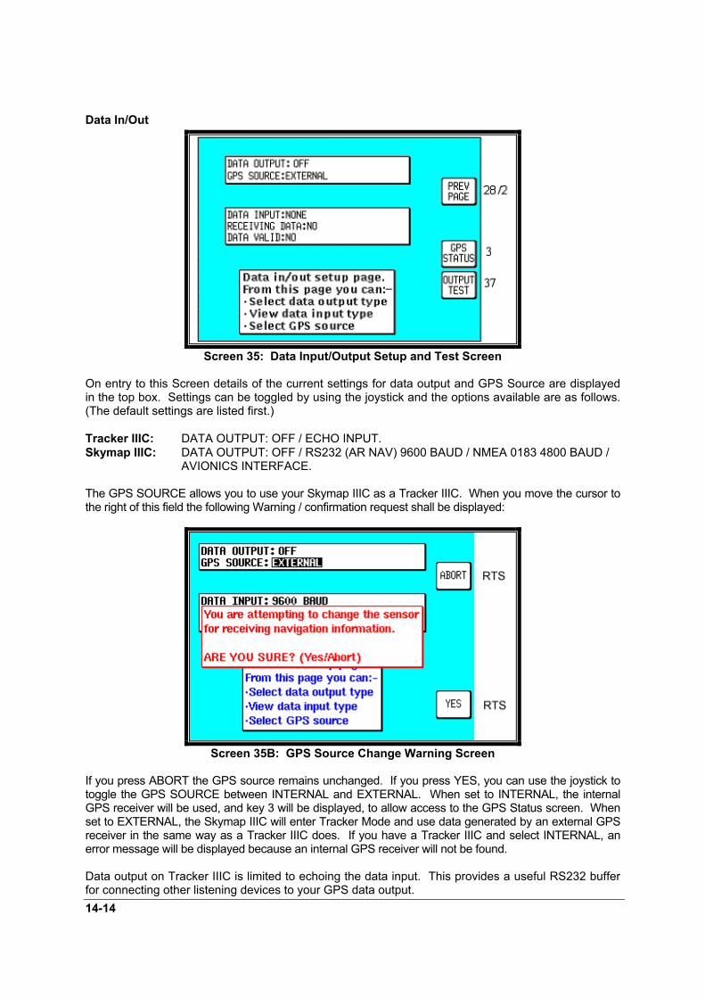
14-14
Data In/Out
Screen 35: Data Input/Output Setup and Test Screen
On entry to this Screen details of the current settings for data output and GPS Source are displayedin the top box. Settings can be toggled by using the joystick and the options available are as follows.(The default settings are listed first.)
Tracker IIIC: DATA OUTPUT: OFF / ECHO INPUT.Skymap IIIC: DATA OUTPUT: OFF / RS232 (AR NAV) 9600 BAUD / NMEA 0183 4800 BAUD / AVIONICS INTERFACE.
The GPS SOURCE allows you to use your Skymap IIIC as a Tracker IIIC. When you move the cursor tothe right of this field the following Warning / confirmation request shall be displayed:
Screen 35B: GPS Source Change Warning Screen
If you press ABORT the GPS source remains unchanged. If you press YES, you can use the joystick totoggle the GPS SOURCE between INTERNAL and EXTERNAL. When set to INTERNAL, the internalGPS receiver will be used, and key 3 will be displayed, to allow access to the GPS Status screen. Whenset to EXTERNAL, the Skymap IIIC will enter Tracker Mode and use data generated by an external GPSreceiver in the same way as a Tracker IIIC does. If you have a Tracker IIIC and select INTERNAL, anerror message will be displayed because an internal GPS receiver will not be found.
Data output on Tracker IIIC is limited to echoing the data input. This provides a useful RS232 bufferfor connecting other listening devices to your GPS data output.

14-15
Skymap IIIC can output standard aviation RS232 data at 9600 baud or NMEA 0183 format RMC,GGA and RMB sentences at 4800 baud. See Appendix 05 for full details.
The AVIONICS INTERFACE output setting for Skymap IIIC is for use when connected to theBendix/King Avionics Interface Module (AIM). The AIM is an optional accessory allowing you toconnect your Skymap IIIC up to other aircraft instruments including the Autopilot. Key 4 will onlyappear if the AVIONICS INTERFACE output is selected and calls Screen 37, the output test page(Skymap IIIC only).
The second box is for information only, and is only show when the GPS Source is External. The unitwill automatically sense the type of incoming data. It first sets up the default data type and then if theincoming data is not recognised, it steps through the other data input options until it finds a format itrecognises.
The data type the unit is looking for will be displayed next to the DATA INPUT heading. Once a validformat is found, searching will be disabled. For Skymap IIIC there are no valid data input types.Tracker IIIC can accept NMEA, AR-NAV (RS 232) and Northstar binary data at either 1200, 4800 or9600 baud. See section 7, Data Input for further details.
Once a valid format is recognised and sentences are being decoded, the word YES will be displayednext to RECEIVING DATA. If the data is not recognised or is not present, the word NO will bedisplayed. If the data is valid and useable, the word YES will appear next to the words DATA VALID,if the data is not valid or useable then the word NO will be displayed.
When Skymap IIIC is used with an external GPS source, the data output will be limited to OFF andECHO INPUT.
Output Test
Screen 37: Aviation Interface Output Test Screen (Skymap IIIC only)
This Screen is designed to output test data to a Bendix/King Avionics Interface Module (AIM) for useduring installation and testing. It is not a Screen with which you as user of the Skymap IIIC needgreatly concern yourself. Should you inadvertently enter it (by pressing Key 4 on Screen 35) you canreturn to Screen 35 simply by pressing Key 1, labelled PREV PAGE.


Appendix 01 - 1
APPENDIX 01: Warning Screens
RAM Lost Warning
Screen 51: RAM Lost Warning Screen
This screen is displayed after power-on if any of the RAM areas are found to be corrupted. Key 1 invokesa RAM clear to be carried out on the failed area and the last known good values to be reinstated. If thelast known good values are also suspect, a full RAM clear of the affected data will be carried out.
Memory Battery Warning
Screen 52: Memory Battery Warning Screen
This Screen will appear if during initialisation the memory battery voltage is found to be low. It canalso appear at any time during operation if the internal battery falls below a pre-determined limit.
By pressing Key 1 you can return to whichever Screen was showing before the low voltage conditionwas detected. If this screen is displayed, you should have your memory battery replaced byyour Bendix/King dealer at the earliest possible opportunity.

Appendix 01 - 2
PIN Lock Warning
Screen 54: Power On Security PIN Entry Screen
If the Auto Power-On Lock function has been activated on Screen 26, this Screen will be called duringinitialisation. You must then input the correct PIN before you are allowed to move back to Screen 1with full access to all functions.
If an incorrect PIN is entered, Screen 25 will appear and Key 1 will revert to this Screen. If anincorrect PIN is entered on three consecutive attempts, even if the unit has been switched off andback on again between attempts, Screen 55 will appear. The number of incorrect attempts thathave been made is stored in NVM and increased with each incorrect attempt or cleared down onceyou have managed to enter the correct PIN.
As the PIN is entered, asterisk characters are displayed in place of the question marks. Key 1 can beused as a Back-Space Key.
Lock Out Warning
Screen 55: Lockout Screen
This Screen will only appear after three incorrect PIN's have been entered on Screen 54 (or if whenyou switch the unit on the NVM is found to have accumulated three unsuccessful PIN input attempts).
The LOCK OUT number is a random five digit number that the unit generates. This is held in RAMand does not change until an unlock number is entered. The unit can be switched off and on with thisScreen showing but the LOCK OUT number will remain the same.

Appendix 01 - 3
If you get locked out of the unit, in order to re-activate the unit, you will need to telephone Honeywellor your local Bendix/King dealer and provide them with your Serial Number and the Lockout Number. Your details will be verified and checked against the Honeywell database and register of stolen units. Once the operator is satisfied that the unit has not been stolen and that you are the officiallyrecognised owner, you will be given an Unlock Code Number.
This Unlock Code is a 10-digit number. You must enter this into your unit on Screen 55. The digitswill replace the question marks as each one is entered. The Unlock Number is deemed to be enteredas the last digit is input. Every time an incorrect unlock number is entered, the unit will generate anew LOCK OUT number. This makes it impossible for a would be thief to stumble upon the unlocknumber by trial and error. The chances of guessing the correct unlock code are 10 million to 1.
Once a lock out has occurred and the unit has been re-activated with an unlock number, the PIN willbe reset to the default of 1234.
Be very careful if you activate the Auto Power On Lock feature. Locking yourself out of thesystem can be very inconvenient.
New Data Card Warning
Screen 56: Flight Plan Change Warning Screen
If, during initialisation, the unit detects a new memory card, the software will check through the flightplans programmed into the unit and validate the data.
Whenever you build a flight plan by using items from the memory card, the Name, Lat. and Long ofeach chosen item is copied into RAM along with a note of which database and which country youextracted it. When a new memory card is detected, each item in each flight plan is checked againstthe new database.
This is done by reading the first item from the first flight plan in RAM and conducting a search throughthe relevant part of the new memory card looking for a Name match. If a perfect match is found forthe Name, the Lat. and Long are then checked and if they match correctly also, then no action isrequired and the software goes on to check the next item.
If a discrepancy is found in either, Lat. or Long, Screen 56 will appear showing the new informationfor the User waypoint in question. You must confirm that you are aware of the change by pressingKey 1.
If no match can be found for the name (i.e. the name has been changed or the item has been deletedfrom the new database) the Lat. and Long fields on Screen 56 will be left blank and the bottomsection of the box will read:

Appendix 01 - 4
CHANGING DATABASE REFERENCEPLEASE CONFIRM
Pressing Key 1 will change the database reference displayed on Screen 12, Flight Plan Program/EditScreen, to OW indicating that this item is now an Old User Waypoint and is no longer accessible fromany database.
This check is carried out for every point in every flight plan and whenever discrepancies are found,Screen 56 will appear on each occasion.

Appendix 02 - 1
APPENDIX 02: Memory Cards
Data AreasHoneywell produce a series of memory cards based on the ICAO/ARINC geographic areas forSkymap IIIC and Tracker IIIC that cover the entire world. Each card for each area contains theoperating software, the appropriate Jeppesen aeronautical data and cartographic data to a highresolution. Also included is a low resolution map of the rest of the world.
The ten ICAO/ARINC areas along with their three letter identifiers are:
EUR Europe CAN Canada MES Middle EastUSA USA PAC Pacific EEU Eastern EuropeSPA South Pacific LAM Latin America AFR AfricaSAM South America
These areas are combined in various ways to produce memory Cards. There are three largetransiting cards available covering the entire world that contain the following data:
AMR Americas - comprising CAN, USA, LAM, SAMATI Atlantic International - comprising EUR, AFR, EEU, MESPAI Pacific International - comprising PAC, SPA, EEU, MES
Numerous other area combinations are also available. Please contact your Bendix/King Dealer forfull details of data card availability.
Changing the memory card.To change the Data Card follow these simple steps:
1. Remove the power/data plug and place the unit face down on a soft surface. A piece of foam or acushion is ideal. Remove the case back by rotating the two DZUS fasteners one turn counterclockwise.
2. Grasp the data card by its edges and pull it straight out of its socket. Do not twist the Card out ofthe socket, this could bend or break the gold pins. Being careful to align the card with the socketthen press the new card firmly into place.

Appendix 02 - 2
3. Refit the case back being careful that the blue gasket is properly seated. Do not exert unduedownward force on the DZUS fasteners. Let them pull the case back into place. Switch theunit on and check for correct operation. Screen 56 may be displayed if changes to informationfeatured in your flight plans are detected. Please refer to the NAV Data Card Warning inAppendix 01.
Minimum Safe Altitudes (MSA) Included in the Jeppesen data supplied on your memory card is Grid Minimum Off Route Altitude (GridMORA) data. The correct use of this data is very important for terrain avoidance and hence requiressome further explanation.
This data is split into a series of one degree squares tiles for the entire world. The Grid MORA providesreference point clearance within these tiles. Jeppesen define a reference point as a natural (peak, knoll,hill, etc) or man-made (tower, stack, tank, building, etc) object.
Jeppesen state that Grid MORA values clear all reference points by 1000 feet in areas where the highestreference points are 5000 feet MSL or lower. MORA values clear all reference points by 2000 feet inareas where the highest reference points are 5001 feet MSL or higher. Grid MORAs are defined for allareas.
In Skymap IIIC the Grid MORA information is used in two ways to derive Minimum Safe Altitudes (MSA),firstly during flight plan building and secondly during actual flight.
Flight Plan building.On screen 12, the Flight Plan Program / Edit Screen, as the cursor is moved up and down the flight plan,the MSA for that leg is shown in a box below the LEG and FPLN info box as [LEG MSA: XXXX]. Thisvalue is the highest value Grid MORA found along a ten mile wide corridor (including 5 miles past thewaypoint) centred along each leg. Also shown is the [FPLN MSA: XXXX] which is the highest value legMSA for the entire flight plan.
During FlightAn [MSA:XXXX] box is included on screen 41, the NAV Menu Screen. This displays the highest GridMORA value within a ten mile radius of your present position at all times.
WARNING: The MSA altitudes displayed are advisory in nature only. They should not berelied upon as the sole source of obstacle and terrain avoidance information. Always refer tocurrent aeronautical charts for appropriate minimum clearance altitudes.
Worldwide ICAO Codes.In order to aid use of the Skymap IIIC, especially the area filter used during database selection(Screens 16 and 16A), there follows a full list of all the countries and states that feature in theJeppesen database along with their ICAO codes, Jeppesen standard name and the data area inwhich they are included (refer to the map at the beginning of this appendix).
Official Country Name ICAO Jeppesen Standard Name State AreaACCRA FIR DG ACCRA FIR AFRALGERIA, P. DEMOCRATIC REP OF DA ALGERIA DZA AFRANGOLA, REPUBLIC OF FN ANGOLA AGO AFRANTANANARIVO FIR/UIR FM ANTANANARIVO FIR/UIR AFRANTARCTICA (AFR, INDIAN OC) F1 ANTARCTICA (AFR) AFRASCENSION I FH ASCENSION SHN AFRBENIN, PEOPLES REPUBLIC OF DB BENIN BEN AFRBOTSWANA, REPUBLIC OF FB BOTSWANA BWA AFRBRAZZAVILLE FIR/UIR FC BRAZZAVILLE FIR/UIR AFRBRITISH INDIAN OCEAN TR. FJ BRITISH INDIAN OCEAN TR IOT AFR

Appendix 02 - 3
BURKINA FASO DF BURKINA FASO BFA AFRBURUNDI, REPUBLIC OF HB BURUNDI BDI AFRCAMEROON, UNITED REPUBLIC OF FK CAMEROON CMR AFRCANARY ISLANDS (SPAIN) GC CANARY IS ESP AFRCAPE VERDE, REPUBLIC OF GV CAPE VERDE CPV AFRCENTRAL AFRICAN REPUBLIC FE CENTRAL AFRICAN REP CAF AFRCHAD, REPUBLIC OF FT CHAD TCD AFRCHAGOS ARCHIPELAGO FJ CHAGOS ARCHIPELAGO IOT AFRCOMOROS, ISLAMIC FED REP OF FM COMOROS COM AFRCONGO, REPUBLIC OF THE FC CONGO COG AFRDAKAR FIR/UIR GO DAKAR FIR/UIR AFRDAKAR OCEANIC GO DAKAR OCEANIC AFRDAKHLA AND LAAYOUNE GM DAKHLA AND LAAYOUNE AFRDJIBOUTI, REPUBLIC OF HD DJIBOUTI DJI AFREGYPT, ARAB REPUBLIC OF HE EGYPT EGY AFREQUTORIAL GUINEA, REPUBLIC OF FG EQUTORIAL GUINEA GNQ AFRERITREA HH ERITREA ERI AFRETHIOPIA HA ETHIOPIA ETH AFRGABONESE REPUBLIC FO GABON GAB AFRGAMBIA, REPUBLIC OF THE GB GAMBIA GMB AFRGHANA, REPUBLIC OF DG GHANA GHA AFRGUINEA, REVOL PEOPLES REP OF GU GUINEA REP GIN AFRGUINEA-BISSAU, REPUBLIC OF GG GUINEA-BISSAU GNB AFRIVORY COAST, REPUBLIC OF DI IVORY COAST CIV AFRJOHANNESBURG FIR FA JOHANNESBURG FIR AFRKENYA, REPUBLIC OF HK KENYA KEN AFRLESOTHO, KINGDOM OF FX LESOTHO LSO AFRLIBERIA, REPUBLIC OF GL LIBERIA LBR AFRMALAGASCAR, REPUBLIC OF FM MADAGASCAR MDG AFRMALAWI, REPUBLIC OF FW MALAWI MWI AFRMALI, REPUBLIC OF GA MALI MLI AFRMAURITANIA, ISLAMIC REPUBLIC GQ MAURITANIA MRT AFRMAURITIUS FIR FI MAURITIUS FIR AFRMAYOTTE FM MAYOTTE MYT AFRMELILLA (SPAIN) GE MELILLA ESP AFRMOROCCO, KINGDOM OF GM MOROCCO MAR AFRMOZAMBIQUE, REPUBLIC OF FQ MOZAMBIQUE MOZ AFRN'DJAMENA FIR/UIR FT N'DJAMENA FIR/UIR AFRNAIROBI FIR HK NAIROBI FIR AFRNAMIBIA FY NAMIBIA NAM AFRNIAMEY FIR/UIR DR NIAMEY FIR/UIR AFRNIGER DR NIGER NER AFRNIGERIA, FEDERAL REPUBLIC OF DN NIGERIA NGA AFRREPUBLIC OF MAURITIUS FI MAURITIUS MUS AFRREUNION, DEPARTMENT OF FM REUNION REU AFRROBERTS FIR GL ROBERTS FIR AFRRWANDESE REPUBLIC HR RWANDA RWA AFRSAINT HELENA FH ST HELENA SHN AFRSAL OCEANIC GV SAL OCEANIC AFRSAO TOME & PRINCIPE, DEM REP FP SAO TOME AND PRINCIPE STP AFRSENEGAL, REPUBLIC OF GO SENEGAL SEN AFRSEYCHELLES FIR FS SEYCHELLES FIR AFRSEYCHELLES, REPUBLIC OF FS SEYCHELLES SYC AFRSIERRA LEONE, REPUBLIC OF GF SIERRA LEONE SLE AFRSOC PEO LIBYAN ARAB JAMAHIRIYA HL LIBYA, SPA JAMAHIRIYA LBY AFRSOMALI DEMOCRATIC REPUBLIC HC SOMALIA SOM AFRSOUTH AFRICA, REPUBLIC OF FA SOUTH AFRICAN REP ZAF AFRSUDAN, REPUBLIC OF THE HS SUDAN SDN AFRSWAZILAND, KINGDOM OF FD SWAZILAND SWZ AFR

Appendix 02 - 4
TANZANIA, UNITED REPUBLIC OF HT TANZANIA TZA AFRTOGOLESE REPUBLIC DX TOGO TGO AFRTUNISIA, REPUBLIC OF DT TUNISIA TUN AFRUGANDA, REPUBLIC OF HU UGANDA UGA AFRZAIRE, REPUBLIC OF FZ ZAIRE ZAR AFRZAMBIA, REPUBLIC OF FL ZAMBIA ZMB AFRZIMBABWE, REPUBLIC OF FV ZIMBABWE ZWE AFROfficial Country Name ICAO Jeppesen Standard Name State AreaALASKA PA ALASKA USA CANALBERTA CY ALBERTA CAN CANBRITISH COLUMBIA CY BRITISH COLUMBIA CAN CANCANADA CY CANADA CAN CANMANITOBA CY MANITOBA CAN CANNEW BRUNSWICK CY NEW BRUNSWICK CAN CANNEWFOUNDLAND CY NEWFOUNDLAND CAN CANNORTHWEST TERRITORIES CY NORTHWEST TERRITORIES CAN CANNOVA SCOTIA CY NOVA SCOTIA CAN CANONTARIO CY ONTARIO CAN CANPRINCE EDWARD ISLAND CY PRINCE EDWARD ISLAND CAN CANQUEBEC CY QUEBEC CAN CANSAINT PIERRE AND MIQUELON CF ST PIERRE I SPM CANSAINT PIERRE AND MIQUELON CF MIQUELON I SPM CANSASKATCHEWAN CY SASKATCHEWAN CAN CANYUKON TERRITORY CY YUKON TERRITORY CAN CANOfficial Country Name ICAO Jeppesen Standard Name State AreaARMENIA, REPUBLIC OF UG ARMENIA ARM EEUAZERBAIJANI REPUBLIC UB AZERBAIJAN AZE EEUBELARUS, REPUBLIC OF UM BELARUS BLR EEUBULGARIA, REPUBLIC OF LB BULGARIA BGR EEUCHINA, PEOPLES REPUBLIC OF ZB CHINA, PR OF CHN EEUCHINA, PEOPLES REPUBLIC OF ZG CHINA, PR OF CHN EEUCHINA, PEOPLES REPUBLIC OF ZL CHINA, PR OF CHN EEUCHINA, PEOPLES REPUBLIC OF ZP CHINA, PR OF CHN EEUCHINA, PEOPLES REPUBLIC OF ZU CHINA, PR OF CHN EEUCHINA, PEOPLES REPUBLIC OF ZY CHINA, PR OF CHN EEUCHINA, PEOPLES REPUBLIC OF ZW CHINA, PR OF CHN EEUCHINA, PEOPLES REPUBLIC OF ZH CHINA, PR OF CHN EEUCHINA, PEOPLES REPUBLIC OF ZS CHINA, PR OF CHN EEUCZECH REPUBLIC LK CZECH CZE EEUGEORGIA, REPUBLIC OF UG GEORGIA GEO EEUHUNGARIAN PEOPLE'S REPUBLIC LH HUNGARY HUN EEUKAZAKHSTAN, REPUBLIC OF UT KAZAKHSTAN KAZ EEUKAZAKHSTAN, REPUBLIC OF UA KAZAKHSTAN KAZ EEUKAZAKHSTAN, REPUBLIC OF UR KAZAKHSTAN KAZ EEUKOREA, DEMOCRAT PEOPLES REP OFZK KOREA, DPR OF PRK EEUKYRGYZ REPUBLIC UA KYRGYZSTAN KGZ EEULATVIA, REPUBLIC OF EV LATVIA LVA EEULITHUANIA, REPUBLIC OF EY LITHUANIA LTU EEUMOLDOVA, REPUBLIC OF LU MOLDOVA MDA EEUMONGOLIA ZM MONGOLIA MNG EEUPOLISH PEOPLES REPUBLIC EP POLAND POL EEUREPUBLIC OF ESTONIA EE ESTONIA EST EEUROMANIA, SOCIALIST REPUBLIC OF LR ROMANIA ROM EEURUSSIAN FEDERATION UN RUSSIA RUS EEURUSSIAN FEDERATION US RUSSIA RUS EEURUSSIAN FEDERATION UM RUSSIA RUS EEURUSSIAN FEDERATION UR RUSSIA RUS EEURUSSIAN FEDERATION UE RUSSIA RUS EEURUSSIAN FEDERATION UH RUSSIA RUS EEU

Appendix 02 - 5
RUSSIAN FEDERATION UU RUSSIA RUS EEURUSSIAN FEDERATION UL RUSSIA RUS EEURUSSIAN FEDERATION UO RUSSIA RUS EEURUSSIAN FEDERATION UI RUSSIA RUS EEURUSSIAN FEDERATION UW RUSSIA RUS EEUSLOVAK REPUBLIC LZ SLOVAKIA SVK EEUTAJIKISTAN, REPUBLIC OF UT TAJIKISTAN TJK EEUTURKMENISTAN UT TURKMENISTAN TKM EEUUKRAINE UK UKRAINE UKR EEUUZBEKISTAN, REPUBLIC OF UT UZBEKISTAN UZB EEUOfficial Country Name ICAO Jeppesen Standard Name State AreaALBANIA, REPUBLIC OF LA ALBANIA ALB EURAUSTRIA, REPUBLIC OF LO AUSTRIA AUT EURAZORES (PORTUGAL) LP AZORES PRT EURBELGIUM EB BELGIUM BEL EURBOSNIA AND HERZEGOVINA, REP OF LQ BOSNIA AND HERZEGOVINA BIH EURCROATIA, REPUBLIC OF LD CROATIA HRV EURDENMARK EK DENMARK DNK EURFAROE ISLANDS (DENMARK) EK FAROE IS FRO EURFINLAND EF FINLAND FIN EURFRENCH REPUBLIC LF FRANCE FRA EURGERMANY, FEDERAL REPUBLIC OF ET GERMANY DEU EURGERMANY, FEDERAL REPUBLIC OF ED GERMANY DEU EURGIBRALTAR LX GIBRALTAR GIB EURGREECE (HELLENIC REPUBLIC) LG GREECE GRC EURGREENLAND BG GREENLAND GRL EURICELAND, REPUBLIC OF BI ICELAND ISL EURIRELAND EI IRELAND IRL EURITALIAN REPUBLIC LI ITALY ITA EURLUXEMBOURG, GRAND DUCHY OF EL LUXEMBOURG LUX EURMACEDONIA LW MACEDONIA MKD EURMADEIRA ISLANDS (PORTUGAL) LP MADEIRA IS PRT EURMALTA, REPUBLIC OF LM MALTA MLT EURNETHERLANDS EH NETHERLANDS NLD EURNORWAY EN NORWAY NOR EURPORTUGUESE REPUBLIC LP PORTUGAL PRT EURREPUBLIC OF SLOVENIA LJ SLOVENIA SVN EURSANTA MARIA OCEANIC LP SANTA MARIA OCEANIC EURSHANWICK OCEANIC EG SHANWICK OCEANIC EURSPANISH STATE LE SPAIN ESP EURSWEDEN, KINGDOM OF ES SWEDEN SWE EURSWISS CONFEDERATION LS SWITZERLAND CHE EURU. KINGDOM OF G.B. AND N. IRE. EG UNITED KINGDOM GBR EURYUGOSLAVIA, FED REP OF LY YUGOSLAVIA YUG EUROfficial Country Name ICAO Jeppesen Standard Name State AreaANGUILLA TQ ANGUILLA AIA LAMANTIGUA AND BARBUDA TA ANTIGUA ATG LAMARUBA TN ARUBA ANT LAMBARBADOS TB BARBADOS BRB LAMBELIZE MZ BELIZE BLZ LAMCAICOS ISLANDS MB CAICOS IS TCA LAMCAYMAN ISLANDS MW CAYMAN IS CYM LAMCOSTA RICA, REPUBLIC OF MR COSTA RICA CRI LAMCUBA, REPUBLIC OF MU CUBA CUB LAMDOMINICA TD DOMINICA DMA LAMDOMINICAN REPUBLIC MD DOMINICAN REPUBLIC DOM LAMEL SALVADOR, REPUBLIC OF MS EL SALVADOR SLV LAMGRENADA TG GRENADA GRD LAMGUADELOUPE, DEPARTMENT OF TF GUADELOUPE GLP LAM

Appendix 02 - 6
GUATEMALA, REPUBLIC OF MG GUATEMALA GTM LAMHAITI, REPUBLIC OF MT HAITI HTI LAMHONDURAS, REPUBLIC OF MH HONDURAS HND LAMJAMAICA MK JAMAICA JAM LAMMARTINIQUE TF MARTINIQUE MTQ LAMMEXICO (UNITED MEXICAN STATES) MM MEXICO MEX LAMMONTSERRAT TR MONTSERRAT I MSR LAMNETHERLANDS ANTILLES TN NETH ANTILLES ANT LAMNICARAGUA, REPUBLIC OF MN NICARAGUA NIC LAMPANAMA, REPUBLIC OF MP PANAMA PAN LAMPUERTO RICO TJ PUERTO RICO PRI LAMSAINT KITTS AND NEVIS TK NEVIS I KNA LAMSAINT VINCENT & THE GRENADINES TV ST VINCENT VCT LAMSAINT LUCIA TL ST LUCIA LCA LAMSAINT KITTS AND NEVIS TK ST KITTS KNA LAMSAN ANDRES (COLOMBIA) SK SAN ANDRES COL LAMTRINIDAD AND TOBAGO, REP OF TT TOBAGO I TTO LAMTRINIDAD AND TOBAGO, REP OF TT TRINIDAD TTO LAMTURKS AND CAICOS ISLANDS MB TURKS IS TCA LAMVIRGIN ISLANDS OF THE U.S. TI VIRGIN IS VIR LAMVIRGIN ISLANDS, BRITISH TU BRITISH VIRGIN IS VGB LAMOfficial Country Name ICAO Jeppesen Standard Name State AreaAFGHANISTAN, ISLAMIC STATE OF OA AFGHANISTAN AFG MESBAHRAIN FIR/UIR OB BAHRAIN FIR/UIR MESBAHRAIN, STATE OF OB BAHRAIN BHR MESBANGLADESH VG BANGLADESH BGD MESBHUTAN, KINGDOM OF VQ BHUTAN BTN MESCYPRUS, REPUBLIC OF LC CYPRUS CYP MESINDIA, REPUBLIC OF VI INDIA IND MESINDIA, REPUBLIC OF VE INDIA IND MESINDIA, REPUBLIC OF VO INDIA IND MESINDIA, REPUBLIC OF VA INDIA IND MESIRAN, ISLAMIC REPUBLIC OF OI IRAN IRN MESIRAQ, REPUBLIC OF OR IRAQ IRQ MESISRAEL, STATE OF LL ISRAEL ISR MESJEDDAH FIR OE JEDDAH FIR MESJERUSALEM LL JERUSALEM ISR MESJORDAN, HASHEMITE KINGDOM OF OJ JORDAN JOR MESKUWAIT, STATE OF OK KUWAIT KWT MESLEBANESE REPUBLIC OL LEBANON LBN MESMALDIVES VR MALDIVES MDV MESNEPAL, KINGDOM OF VN NEPAL NPL MESOMAN, SULTANATE OF OO OMAN OMN MESPAKISTAN, ISLAMIC REPUBLIC OF OP PAKISTAN PAK MESQATAR, STATE OF OT QATAR QAT MESREPUBLIC OF YEMEN OY YEMEN YEM MESSAUDI ARABIA, KINGDOM OF OE SAUDI ARABIA SAU MESSRI LANKA, DEM SOC REP OF VC SRI LANKA LKA MESSYRIAN ARAB REPUBLIC OS SYRIA SYR MESTURKEY, REPUBLIC OF LT TURKEY TUR MESTURKEY, REPUBLIC OF N CYPRUS LC TURKEY (REP OF N CYPRUS) TUR MESUNITED ARAB EMIRATES OM UNITED ARAB EMIRATES ARE MESOfficial Country Name ICAO Jeppesen Standard Name State AreaCAMBODIA, STATE OF VD CAMBODIA KHM PACCAROLINE ISLANDS PT CAROLINE IS PCI PACCHINA, THE REPUBLIC OF RC TAIWAN TWN PACGUAM PG GUAM GUM PACHAWAII PH HAWAII USA PACHONG KONG VH HONG KONG HKG PAC

Appendix 02 - 7
JAPAN RJ JAPAN JPN PACJAPAN RO JAPAN JPN PACJOHNSTON ATOLL PJ JOHNSTON ATOLL JTN PACKIRIBATI PC KIRIBATI KIR PACKIRIBATI PL KIRIBATI KIR PACKOREA, REPUBLIC OF RK KOREA KOR PACLAO, PEOPLES DEM REP OF VL LAOS LAO PACMACAU VM MACAU MAC PACMARIANA ISLANDS PG MARIANA IS MNP PACMARSHALL ISLANDS PK MARSHALL IS MHL PACMICRONESIA, FED STATES OF PT MICRONESIA FSM PACMIDWAY ISLANDS PM MIDWAY I MID PACMYANMAR, UNION OF VY MYANMAR MMR PACNORTHERN MARIANA ISLANDS PG NORTHERN MARIANA IS MNP PACOAKLAND OCEANIC CONTROL AREA P OAKLAND OCTA USA PACPALAU, REPUBLIC OF PT PALAU PLW PACPHILIPPINES, REPUBLIC OF THE RP PHILIPPINES PHL PACTHAILAND, KINGDOM OF VT THAILAND THA PACVIETNAM, SOCIALIST REP OF VV VIETNAM VNM PACWAKE ISLAND PW WAKE I XJW PACOfficial Country Name ICAO Jeppesen Standard Name State AreaANTARCTICA (ARG, CHILE) S1 ANTARCTICA (ARG, CHILE) SAMARGENTINA, REPUBLIC OF SA ARGENTINA ARG SAMBOLIVIA, REPUBLIC OF SL BOLIVIA BOL SAMBRAZIL, FED. REPUBLIC OF SB BRAZIL BRA SAMCHILE, REPUBLIC OF SC CHILE CHL SAMCOLOMBIA, REPUBLIC OF SK COLOMBIA COL SAMECUADOR SE ECUADOR ECU SAMFALKLAND ISLANDS SF FALKLAND IS FLK SAMFRENCH GUIANA SO FRENCH GUIANA GUF SAMGUYANA, REPUBLIC OF SY GUYANA GUY SAMPARAGUAY, REPUBLIC OF SG PARAGUAY PRY SAMPERU, REPUBLIC OF SP PERU PER SAMSURINAME, REPUBLIC OF SM SURINAME SUR SAMURUGUAY, REPUBLIC OF SU URUGUAY URY SAMVENEZUELA, REPUBLIC OF SV VENEZUELA VEN SAMOfficial Country Name ICAO Jeppesen Standard Name State AreaANTARCTICA (AUS, NZ) A1 ANTARCTICA (AUS, NZ) SPAAUSTRALIA YM AUSTRALIA AUS SPAAUSTRALIA YS AUSTRALIA AUS SPAAUSTRALIA YP AUSTRALIA AUS SPAAUSTRALIA YB AUSTRALIA AUS SPABRUNEI DARUSSALAM WB BRUNEI BRN SPACOOK ISLANDS NC COOK IS COK SPAEASTER ISLAND (CHILE) SC EASTER I CHL SPAFIJI NF FIJI IS FJI SPAFRENCH PACIFIC OVERSEAS TERR. NT FRENCH PACIFIC PYF SPAINDONESIA, REPUBLIC OF WA INDONESIA IDN SPAINDONESIA, REPUBLIC OF WR INDONESIA IDN SPAINDONESIA, REPUBLIC OF WP INDONESIA IDN SPAINDONESIA, REPUBLIC OF WI INDONESIA IDN SPAKIRIBATI NG KIRIBATI KIR SPAMALAYSIA WM MALAYSIA MYS SPAMALAYSIA WB MALAYSIA MYS SPANAURU, REPUBLIC OF AN NAURU NRU SPANEW CALEDONIA NW NEW CALEDONIA NCL SPANEW ZEALAND NZ NEW ZEALAND NZL SPANIUE NI NIUE NIU SPAPAPUA NEW GUINEA AY PAPUA NEW GUINEA PNG SPA

Appendix 02 - 8
SAMOA, AMERICAN NS AMERICAN SAMOA ASM SPASAMOA, INDEP STATE OF WESTERN NS WESTERN SAMOA WSM SPASINGAPORE, REPUBLIC OF WS SINGAPORE SGP SPASOCIETY ISLANDS NT SOCIETY IS PYF SPASOLOMON ISLANDS AG SOLOMON IS SLB SPATONGA, KINGDOM OF NF TONGA TON SPATUAMOTU ISLANDS NT TUAMOTU IS PYF SPATUVALU NG TUVALU TUV SPAVANUATU, REPUBLIC OF NV VANUATU VUT SPAWALLIS AND FUTUNA ISLANDS NL FUTUNA IS WLF SPAWALLIS AND FUTUNA ISLANDS NL WALLIS IS WLF SPAOfficial Country Name ICAO Jeppesen Standard Name State AreaALABAMA K7 ALABAMA USA USAARIZONA K2 ARIZONA USA USAARKANSAS K4 ARKANSAS USA USABAHAMAS, COMMONWEALTH OF THE MY BAHAMAS BHS USABERMUDA ISLANDS TX BERMUDA BMU USACALIFORNIA K2 CALIFORNIA USA USACOLORADO K2 COLORADO USA USACONNECTICUT K6 CONNECTICUT USA USADELAWARE K6 DELAWARE USA USADISTRICT OF COLUMBIA K6 DISTRICT OF COLUMBIA USA USAFLORIDA K7 FLORIDA USA USAGEORGIA K7 GEORGIA USA USAIDAHO K1 IDAHO USA USAILLINOIS K5 ILLINOIS USA USAINDIANA K5 INDIANA USA USAIOWA K3 IOWA USA USAKANSAS K3 KANSAS USA USAKENTUCKY K5 KENTUCKY USA USALOUISIANA K4 LOUISIANA USA USAMAINE K6 MAINE USA USAMARYLAND K6 MARYLAND USA USAMASSACHUSETTS K6 MASSACHUSETTS USA USAMICHIGAN K5 MICHIGAN USA USAMINNESOTA K3 MINNESOTA USA USAMISSISSIPPI K7 MISSISSIPPI USA USAMISSOURI K3 MISSOURI USA USAMONTANA K1 MONTANA USA USANEBRASKA K3 NEBRASKA USA USANEVADA K2 NEVADA USA USANEW MEXICO K2 NEW MEXICO USA USANEW YORK K6 NEW YORK USA USANEW HAMPSHIRE K6 NEW HAMPSHIRE USA USANEW JERSEY K6 NEW JERSEY USA USANORTH CAROLINA K7 NORTH CAROLINA USA USANORTH DAKOTA K3 NORTH DAKOTA USA USAOAKLAND OCEANIC CONTROL AREA K2 UNITED STATES OF AMERICA USA USAOAKLAND OCEANIC CONTROL AREA K1 UNITED STATES OF AMERICA USA USAOHIO K5 OHIO USA USAOKLAHOMA K4 OKLAHOMA USA USAOREGON K1 OREGON USA USAPENNSYLVANIA K6 PENNSYLVANIA USA USARHODE ISLAND K6 RHODE ISLAND USA USASOUTH CAROLINA K7 SOUTH CAROLINA USA USASOUTH DAKOTA K3 SOUTH DAKOTA USA USATENNESSEE K7 TENNESSEE USA USATEXAS K4 TEXAS USA USAUNITED STATES OF AMERICA K4 HOUSTON OCEANIC USA USA

Appendix 02 - 9
UNITED STATES OF AMERICA K6 NEW YORK OCEANIC USA USAUNITED STATES OF AMERICA K7 MIAMI OCEANIC USA USAUTAH K2 UTAH USA USAVERMONT K6 VERMONT USA USAVIRGINIA K6 VIRGINIA USA USAWASHINGTON K1 WASHINGTON USA USAWEST VIRGINIA K6 WEST VIRGINIA USA USAWISCONSIN K5 WISCONSIN USA USAWYOMING K1 WYOMING USA USA


Appendix 03 - 1
APPENDIX 03: How Does GPS Work?
What Is GPS?Many of the radio-navigation aids used in aviation were originally developed for military use but havenow been made freely available to civil users. The Global Positioning System (GPS) has a similarhistory. The GPS constellation of satellites is an American military facility operated by the USDepartment of Defence (DoD). This constellation consists of 21 operational satellites plus threespares held in reserve to replace any of the active ones, which might fail. They orbit approximately10,900 N.M. above the earth in six planes inclined at a 55 degree angle to the Equator and circle theearth twice daily. The orbits are so arranged that a minimum of four satellites will always be visiblefrom any part of the earth's surface at any time. This allows suitable receivers to make extremelyaccurate determination of latitude, longitude, altitude, velocity and time from satellite signals receivedby an aircraft, airborne or on the ground.
How Does It Work?Each satellite carries an extremely accurate atomic clock and continuously transmits precise timingwaveforms and data concerning its health status and almanac, orbital information and clock timingcorrections. The signals have been designed to be extremely resistant to interference from terrestrialradio transmissions, electronic equipment and weather.
The technique used to establish position using these satellites is one of simple ranging. In otherwords, position is calculated from measurements of the distances between the observer and anumber of satellites. The exact position of each satellite at any given time is known. This informationis actually transmitted by each satellite every few minutes. The precise time (in relation to UniversalTime) that each satellite starts to transmit its coded signal is also known.
Given this information and the speed of radio waves through space, it is possible to establish theexact distance from each satellite by simple mathematics. For example, if a car leaves point A atexactly 1 o'clock and travels at sixty miles an hour to point B which it reaches at exactly 2 o'clock, weknow the distance between points A and B must be sixty miles.
In order to achieve the required degree of accuracy from this technique it would normally benecessary to have an extremely accurate atomic clock built into each receiver as well as eachsatellite. This would not be viable, as each receiver would then cost tens of thousands of pounds.Instead, an ingenious system is used whereby GPS receivers require to be fitted with only reasonablyaccurate (and thus low-cost) clocks. This involves two important techniques:
1) Code matching or synchronisation. Each satellite transmits, for civilian use, a unique 1023 bitcode. This code is repeated every millisecond (one thousandth of a second). In the receiver, circuitry generates an identical code that is then slid back and forth in time until itexactly matches the code being received from the satellite.
When a perfect match is achieved, the time at which the receiver is generating the start bit of thecode is recorded. The difference in time (or offset) between the receiver generating the code and thesatellite generating the code is therefore measurable because the time at which the satellite shouldhave generated the code is known.
This gives a very accurate way of measuring the time differences between transmission and receptionof the signals generated by the satellites, but does not help with the need for an absolute timereference. One must bear in mind that if the clock in the receiver were only 100 milliseconds (onetenth of a second) out with respect to universal time, the calculated distance from the satellite wouldhave an error of 1,860 miles.
This problem is overcome by a second technique:

Appendix 03 - 2
2) Making use of an extra satellite. In order to obtain a positional fix in three dimensional space, itis necessary to know the exact distance to each of three satellites. The exact distance is however notknown because of the presence of an offset or error in the receiver's clock with respect to universaltime.
A fix is nevertheless calculated using the three satellites, all be it erroneous. Once this fix iscalculated, a second fix is calculated using satellites 2 and 3 in conjunction with a fourth satellite. This is repeated for satellites 3, 4 and 1 then 4, 1 and 2. This gives four calculated points in space.
If the four calculated points do not overlap, a timing error must be present.
A slight correction is then fed into the receiver's clock and the points are calculated again. They movecloser to each other.
This process is repeated until all the calculations tie up correctly at the same point. The exactposition in three-dimensional space is then known and the offset in the receiver's clock eliminated.
Similarly, a two-dimensional fix can be established from three satellites.
As a result of this technique the receiver does not initially need to know absolute universal time. Allthat is needed is a reasonably stable clock for taking relative measurements over the short periodsbetween the signals received from each satellite.
An approximate knowledge of universal time is required, to know which satellite to expect in whichpart of the sky. This is usually given by the first satellite the receiver acquires after switch on. The exact universal time is transmitted as part of the almanac and health status data by each satellite. This is then corrected by the receiver for signal transition delay as part of the position fix calculations.
Accuracy and ReliabilityAll GPS satellites transmit two separate pseudo-random codes on two different frequencies. The most accurate is the P code, which is transmitted at both 1.2276 GHz (1.2276 thousand millioncycles per second) and 1.57542 GHz.
The P code is extremely complex and has a repetition rate of one week. This code is restricted tomilitary use only, is capable of supreme accuracy and is supposedly unbreakable.
The signal available to civilian users is transmitted on 1.57542 GHz only and is called the C/A code. C/A stands for Coarse Acquisition.
This code is relatively simple compared to the P code and has a repetition rate of one millisecond.
The present maximum accuracy for receivers using the C/A code is 15 meters. There is the possibility however of this being intentionally degraded (by feeding random errors into thesatellite clocks) to 100 meters for strategic reasons. This is called Selective Availability or S/A andcan be implemented at will by the DoD.
Day to day accuracy is monitored by Falcon Air Force Base, Colorado, who receive information froma group of ground stations positioned at Ascension Island, Diego Garcia, Kwagale and Hawaii.
These stations receive the satellite signals and check them for timing accuracy. If any errors aredetected, error information is transmitted back to the satellite, which then corrects itself.
Reliability should be good when the full constellation of 24 satellites are in orbit.

Appendix 03 - 3
Each satellite has three separate clocks on board (one in use and two standby) and in the event ofthe total failure of a satellite, one of the spares already in orbit can be manoeuvred into position withina few hours.
The only time the DoD can predict there may be a substantial break in coverage for civilian users, isat a time of National Emergency, when the whole system may be reverted to P code (military)operation only, for strategic reasons.
Having said this, the system remained fully available to civilian users during the Gulf conflict.


Appendix 04 - 1
APPENDIX 04: Differential Functions (Skymap IIIC only)Your Bendix/King unit has been designed to enable it to make use of Differential GPS (DGPS).
What Is DGPS?GPS on its own is, as we have seen in Appendix 03, an extremely accurate system for all generalnavigation purposes. It is not, however, perfect. The most significant source of error in GPS positionalcalculations is the deliberate downgrading of accuracy known as Selective Availability (SA) described inAppendix 03. Satellite clocks, although superbly accurate, also have tiny errors, which can affect theaccuracy of a fix. So also does any slight drift from a satellite's predicted orbit. The signals from satelliteshave to pass through the earth's atmosphere and, although radio signals travel at the speed of light, this isonly a constant through a vacuum. Things like water vapour in the troposphere and charged particles inthe ionosphere do slow down satellite signals and cause slight delays that translate into errors in position.And finally it must be admitted that GPS receivers are not perfect either. These can themselves inducefurther small positional errors, mainly as a result of receiver noise or clock inaccuracy.
DGPS can virtually cancel out all of the errors due to SA, to orbital errors and to satellite clock inaccuracy.It also greatly reduces any error caused by the atmospheric delay to radio signals. What DGPS cannotcorrect for are only the inaccuracies due to the GPS receiver itself and possible “multi-path” errors which(like “ghosting” on a TV) are due to secondary signals being received after reflection off local obstructions.The net result of all this is that while standard GPS can experience errors of between 15 and 100 metres(depending largely on whether SA is active or not) DGPS is already capable of accuracy’s down to 1.3metres horizontally and 2.0 metres vertically.
How Does DGPS Work?Any two GPS receivers within a few hundred miles of each other will receive satellite signals, which havebeen affected by virtually the same errors as each other. The signals emanate from the same group ofsatellites, travel through the same portion of the earth's atmosphere and so will be subjected to the samedelays. Thus, all the errors (except those due to multi-pathing and to the receivers themselves) will becommon to both. So if one of these receivers is located at a fixed point, which has been extremely andprecisely surveyed, it can be used as a reference. Instead of using the signals to calculate its position,since it already knows its position it can calculate the errors in the incoming signals.
Having established the magnitude of the errors all that is then needed is an associated transmitterbroadcasting signals to tell any mobile GPS receivers in the area exactly what these errors are. Themobile GPS's are then able to use this data to correct for the errors in their raw calculations and to comeup with the positional accuracy’s mentioned above. DGPS even removes the deliberate degrading ofaccuracy associated with the DoD's Selective Availability. It is essential to process the data from thereference receiver very rapidly and to transmit the correction data to the mobile GPS receivers almostinstantaneously since, especially if SA is active, these errors are constantly varying. Transmitters andreceivers have to be designed to work at high baud (bits per second) rates to transfer the necessary databefore it becomes out of date.
Uses Of DGPSStandard GPS provides very adequate accuracy for most navigational tasks, but the additional precisionavailable through DGPS opens up other possibilities in aviation and in many other spheres of activity.Once the aviation authorities are prepared to approve DGPS-based low-visibility approach and landingsystems, these could provide low-cost precision facilities worldwide. The benefits of this could beespecially useful at small airports where the expense of an ILS or MLS system could never be justifiedand in developing countries where few if any navigation aids exist today.

Appendix 04 - 2
DGPS has also already become an essential tool of the offshore oil industry, enabling drill bits to beplaced with more precision than any other system. Marine navigation, survey work and cartography,emergency services, agriculture and forestry and road transport fleet management are just some of thenon-military applications already relying more and more upon the accuracy of DGPS.
Data ConnectionTo operate correctly in differential mode, Skymap IIIC requires a 9600 baud RTCM SVC-104 Version 2.0format sentence.
To connect the Skymap IIIC to a differential receiver unit, common up the 0v or ground lines (pin 5 of theSkymap IIIC connector) and connect the data output line from the differential receiver to pin 1 of theSkymap IIIC connector.
Once connected to an operating differential receiver, switch your Skymap IIIC on and select Screen 3,GPS Status Screen, by pressing Key 1 from the Main Menu Screen. Once the unit has a fix anddifferential sentences are being decoded, the word DIFFERENTIAL will be displayed next to the STATE:heading. If the data is not recognised or is not present, the word DIFFERENTIAL will not be displayed.
All the time that DIFFERENTIAL is displayed, the Skymap IIIC is in differential mode and corrections arebeing applied to the position fix calculations.

Appendix 05 - 1
APPENDIX 05: Skymap IIIC Serial Data Output Sentences.
Skymap IIIC can output standard aviation RS232 data at 9600 baud or NMEA 0183 format RMC,GGA and RMB sentences at 4800 baud. The data output type is Setup on Screen 35 Datainput/output Setup and Test Screen.
NMEA 0183 Data Format. 4800 baud, 8 data bits, 1 stop bit, no parity. Each sentence is followed by a checksum (*hh), carriagereturn (CR) and a line feed (LF). All three sentences sent every two seconds.
NMEA – RMC Sentence.
$GPRMC,<1>,<2>,<3>,<4>,<5>,<6>,<7>,<8>,<9>,<10>,<11>*hh<CR><LF>
<1> UTC time of position fix, hhmmss format.<2> Status, A= Valid position, V=warning<3> Latitude,ddmm.mmm format.<4> Latitude hemisphere, N or S.<5> Longitude, dddmm.mmm format.<6> Longitude hemisphere, E or W.<7> Speed over ground (000.0-999.9 knots).<8> Course over ground (000.0-359.9 true).<9> Date of fix ddmmyy format.<10> Magnetic variation 000.0-180.0o.<11> Variation direction E or W.
Sample sentence.
$GPRMC,132404,A,5111.465,N,00102.845,W,090.0,304.1,020492,004.3,W*7A
NMEA – GGA Sentence.
$GPGGA,<1>,<2>,<3>,<4>,<5>,<6>,<7>,<8>,<9>,M,<10>,M,,*hh<CR><LF>
<1> UTC time of position fix, hhmmss.<2> Latitude, ddmm.mmm format.<3> Latitude hemisphere, N or S.<4> Longitude dddmm.mmm format.<5> Longitude hemisphere, E or W.<6> GPS quality. 0 = no fix, 1 = fix good, 2 = fix good, differential mode.<7> Number of sats in use, 00 to 08.<8> DOP, 01.0 to 99.0.<9> Antenna height above MSL (metres).<10> Geoidal offset in metres.
Sample sentence.
$GPGGA,091636,5119.607,N,00122.001,E,1,04,1.8,18.3,M,-47.0,M,,*5D

Appendix 05 - 2
NMEA – RMB Sentence.
$GPRMB,<1>,<2>,<3>,<4>,<5>,<6>,<7>,<8>,<9>,<10>,<11>,<12>,<13>*hhCRLF
1. Position valid (A = valid, V = invalid).2. XX.XX Cross track error in nautical miles.3. X Direction to steer (L = left, R = right).4. XXXX Four character start waypoint identifier. (first four characters of name).5. XXXX Four character destination waypoint identifier.6. DDMM.MM Destination Lat.7. X Destination hemisphere (N or S).8. DDDMM.MM Destination Long.9. X Destination hemisphere (E or W).10. XXX.X Range to destination in nautical miles.11. XXX.X Bearing to destination TRUE.12. XXX.X closing velocity in knots.13. X Arrival flag. (A = arrival, V = not arrival).
Sample sentence.
$GPRMB,A,00.00,L,1,2,5142.20,N,00217.10,W,048.8,304.0,090.0,V*18
Notes on the RMB sentence.
Note the direction in field 3 is direction to steer, i.e. off track to the right, steer left.
If not in NAV or DIRECT TO mode, the flag in field 1 will show invalid (V).
If in DIRECT TO mode there will be no start point identifier so field 4 will be blank (spaces). If in DIRECTTO mode where the DIRECT TO point is just a point in space with no name, field 5 will be blank (spaces)also.
The arrival flag in field 13 is set to A when the TP imminent message shows on screen and stay set untilthe next leg is selected even if the TP passed message comes up on screen.
At the end of the flight plan or DIRECT TO when the unit drops out of NAV mode, the flag in field 1 willchange to a V.
The closing velocity in field 12 is the vectored velocity towards the waypoint. There is no provision forshowing negative numbers so if answer is negative, all zeros will be sent.

Appendix 05 - 3
RS-232C AR-NAV Data Format9600 baud 8 data bits, 1 stop bit, no parity. Type 1 sentence only sent every two seconds. Each line ofdata is followed by a carriage return (CR) and a line feed (LF) character except the STX and ETX lines.
Header Data Description.STX Hex 02.z aaaaaCRLF GPS altitude in feet.A s dd mmhhCRLF Latitude where s = N or S, dd = degrees
mm = minutes, hh = hundredths of minutes.B s ddd mmhhCRLF Longitude designated as above.C dddCRLF Magnetic track in whole degrees.D sssCRLF Groundspeed in knots.E dddddCRLF Distance to waypoint in 1/10ths of nm.G snnnnCRLF Cross track error where s = L or R (of track)
and nnnn = error in 100ths of an nm.I ddddCRLF Desired magnetic track in 10ths of a degree.
i.e. BRG to waypoint if you were on track.K cccccCRLF Destination waypoint name. Dashes sent after
name if shorter than 5 characters.L ddddCRLF Actual magnetic bearing to WPT (in 1/10ths
of a degree).Q sdddCRLF Variation. s= E or W. ddd = 1/10ths degrees.S ----eCRLF e = NAV flag. - = NAV valid, N = NAV not valid.T ---------CRLF Indicates end of sentence type 1. ETX Hex 03.
Notes on the AR-NAV sentence.
If the unit is not in NAV mode or does not have a fix, dashes (---) will be sent in fields E, G, I, K, L. Part eof field S will be set to N.
If the unit does not have a fix, dashes will be sent in the latitude, longitude, track and ground speed fields.
If the variation value is greater than 99.9°, a fourth character will be sent in the Q field (i.e. sddddCRLF).


Appendix 06 - 1
APPENDIX 06: Service and WarrantyDue to the Company's policy of continual development and routine database updates, new MemoryCards will become available every 28 days. As a registered owner of a Tracker IIIC or Skymap IIIC,you will be offered a 1/3/6/12 monthly Memory Card subscription. Keeping your database currentis your own responsibility and is extremely important from a safety viewpoint.
To validate your warranty you should fill in and return the enclosed Product Registration Cardwithin 10 days of purchase. Failure to register your unit may result in loss of warranty.
Registering your unit is also essential if you wish to receive an unlock code over thetelephone in the event of a PIN lockout. If your unit is not registered, your only option will beto return the unit to a Bendix/King facility. Registering your unit also provides a means ofcontacting you with information on any new memory Card upgrade.
If you have a change of address or sell your unit on to someone else, or if your unit is lost or stolen,please inform us so that we may update our records and keep track of (or help to track down) the unit.
Your unit is warranted to be free from defects in materials or workmanship for a period of two yearsfrom date of purchase. Warranty will not cover failures due to abuse, misuse, accident orunauthorised alteration or repair. In the unlikely event of repairs being necessary, please return thecomplete unit, including antenna, in its carrying case, carriage paid to one of the addresses below.
Skyforce Avionics Ltd Honeywell Inc5 The Old Granary Business & General AviationBoxgrove One Technology CenterChichester 23500 West 105th StreetWest Sussex OlathePO18 0ES KansasUnited Kingdom USATel: +44 (0) 1243 783763 Tel: + 1 913 712 2613Fax +44 (0) 1243 783992 Fax: + 1 913 712 1302
This guarantee does not cover call out or on-site maintenance of the equipment.
If you require further help or advice on installing or operating your unit, please contact in the firstinstance the dealer from whom you purchased the equipment.