skf spherical roller thrust bearings12-121034/0901d... · bearings skf explorer spherical roller...
TRANSCRIPT
SKF spherical roller thrust bearingsFor long lasting performance
The SKF brand now stands for more than ever before, and means more to you as a valued customer.
While SKF maintains its leadership as a high-quality bearing manufacturer throughout the world, new dimensions in technical advances, product support and services have evol ved SKF into a truly solutions-oriented supplier, creating greater value for customers.
These solutions enable customers to improve productivity, not only with breakthrough application-specific prod-ucts, but also through leading-edge design simulation tools and consultancy services, plant asset efficiency mainte-nance program mes, and the industry’s most advanced supply management techniques.
The SKF brand still stands for the very best in rolling bearings, but it now stands for much more.
SKF – the knowledge engineering company
A Product information
3 Conquer misalignment and heavy axial and radial loads
3 Where spherical roller thrust bearings are superior
4 The strength of SKF spherical roller thrust bearings
5 Setting new standards with SKF Explorer bearings
6 Unrivalled range
8 SKF Explorer spherical roller thrust bearings – for premium performance
10 Where heavy combined loads must be accommodated
B Recommendations
12 Selection of bearing size
14 Design of bearing arrangements14 Single direction thrust bearing
arrangements14 Double direction thrust bearing
arrangements16 Axial clearance and preload18 High-speed bearing arrangements18 Low-speed bearing arrangements18 Stiffness18 Design of associated components19 Seals
20 Typical bearing arrangements20 Single direction thrust bearing
arrangements21 Double direction thrust bearing
arrangements
24 Lubrication and maintenance24 Oil lubrication26 Grease lubrication28 Maintenance
Contents
30 Mounting and dismounting30 Mounting31 Dismounting
32 Service for a lasting partnership
C Product data
34 Bearing data – general
36 Product table
D Additional information
44 Related SKF products
46 SKF – the knowledge engineering company
2
Conquer misalignment and heavy axial and radial loads
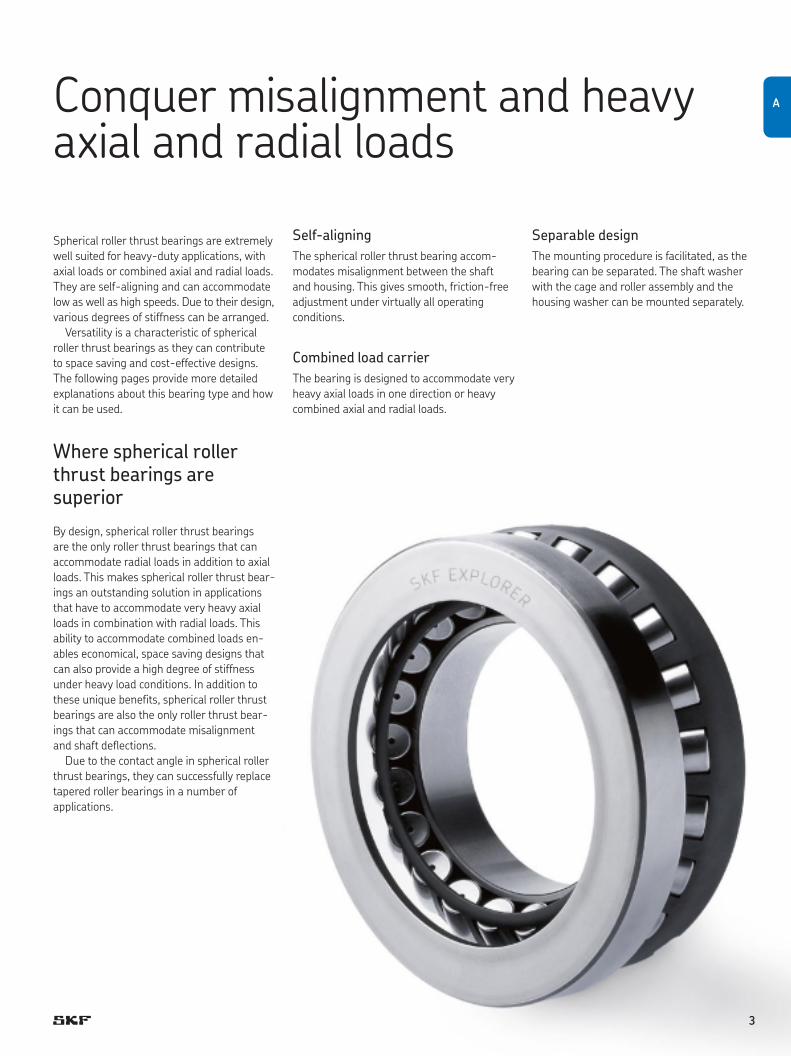
Spherical roller thrust bearings are extremely well suited for heavy-duty applications, with axial loads or combined axial and radial loads. They are self-aligning and can accommodate low as well as high speeds. Due to their design, various degrees of stiffness can be arranged.
Versatility is a characteristic of spherical roller thrust bearings as they can contribute to space saving and cost-effective designs. The following pages provide more detailed explan ations about this bearing type and how it can be used.
Where spherical roller thrust bearings are superior
By design, spherical roller thrust bearings are the only roller thrust bearings that can accommodate radial loads in addition to axial loads. This makes spherical roller thrust bear-ings an outstanding solution in applications that have to accommodate very heavy axial loads in combination with radial loads. This ability to accommodate combined loads en -ables economical, space saving designs that can also provide a high degree of stiffness under heavy load conditions. In addition to these unique benefits, spherical roller thrust bearings are also the only roller thrust bear-ings that can accom mo date misalignment and shaft deflections.
Due to the contact angle in spherical roller thrust bearings, they can successfully replace tapered roller bearings in a number of applications.
Self-aligningThe spherical roller thrust bearing accom-modates misalignment between the shaft and housing. This gives smooth, friction-free adjustment under virtually all operating conditions.
Combined load carrierThe bearing is designed to accommo d ate very heavy axial loads in one direction or heavy combined axial and radial loads.
Separable designThe mounting procedure is facilitated, as the bearing can be separated. The shaft washer with the cage and roller assembly and the housing washer can be mounted separately.
A
3
The strength of SKF spherical roller thrust bearings
Superior bearing service lifeSmooth running and long bearing service life are a result of the internal design that gives the raceways and rollers an optimized balance between contact pressure and friction.
SKF spherical roller thrust bearings are well proven in the field and are subject to continu-ous development to provide improved perform-ance. SKF Explorer performance class bear-ings are a good example of what can be achieved with purposeful development – in this case, opening up new application horizons.
Wide speed rangeLow internal friction permits the bearings to operate from very low to very high speeds. Speeds up to three times the reference speed are possible by adding certain design features. Basically, the speed performance depends on the bearing arrangement, the application and the operating conditions.
Robust designSKF spherical roller thrust bearings are designed for heavy-duty operating conditions and are therefore highly reliable. Made from the unique SKF Xbite heat treated steel, these bearings exhibit excellent wear and fracture toughness characteristics. SKF Xbite heat treated steel also provides high dimensional stability up to 200 °C (390 °F).
Combined load carrierSpherical roller thrust bearings can accom-modate radial loads up to 55 % of the simul-taneously acting axial load. This means that one spherical roller thrust bearing often can be used instead of a combination of a radial and a thrust bearing.
Benefits•Compactbearingarrangement•Reducedarrangementweight•Reducedarrangementcost
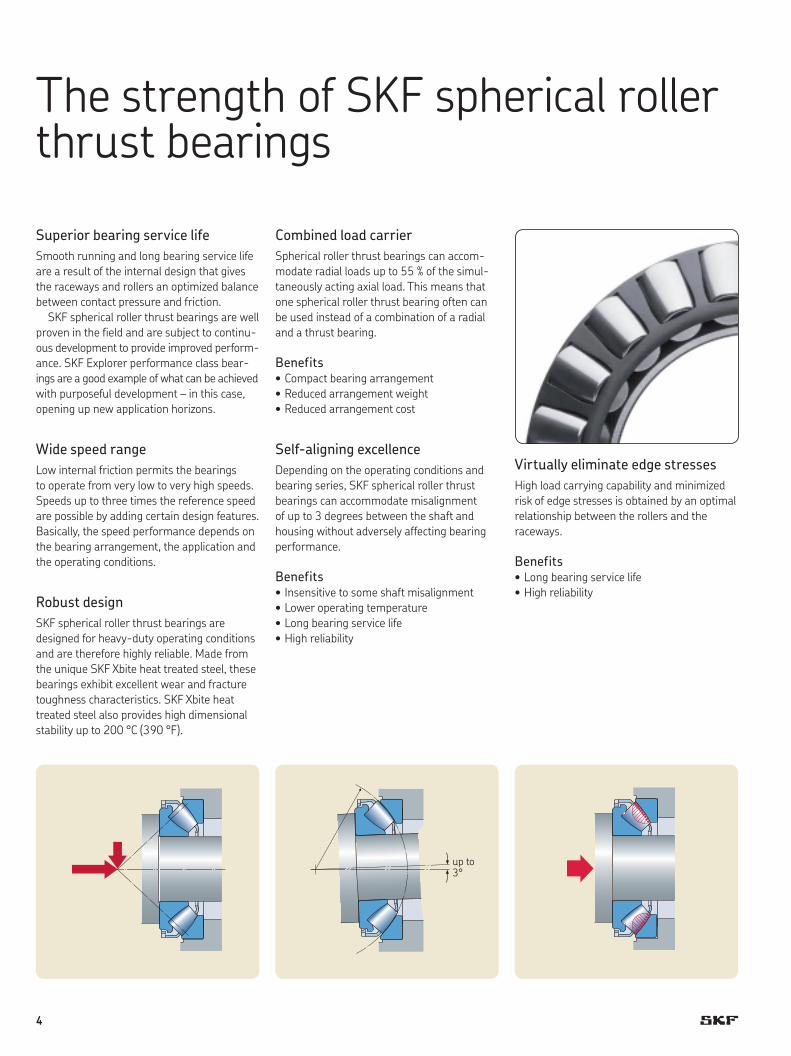
Self-aligning excellenceDepending on the operating conditions and bearing series, SKF spherical roller thrust bearings can accom modate misalignment of up to 3 degrees between the shaft and housing without adversely affecting bearing performance.
Benefits•Insensitivetosome shaft misalignment•Loweroperatingtemperature•Longbearingservicelife•Highreliability
Virtually eliminate edge stressesHigh load carrying capability and minimized risk of edge stresses is obtained by an optimal relationship between the rollers and the raceways.
Benefits•Longbearingservicelife•Highreliability
up to 3°
4

When stiffness countsBy design, spherical roller thrust bearings provide a high degree of stiffness. In addition, high moment stiffness can be achieved when two spherical roller thrust bearings are mounted in a back-to-back arrangement. This is due to the long distance between the pressure centres, where the loads are acting.
Benefits•Minimal bearing arrangement deformation
under radial and axial loads •Minimal bearing arrangement deflection
under moment loads•Compact design
Cool running at high speeds ...Specially designed spherical roller end/flange contacts reduce stress levels and optimize lubricant film formation. This reduces friction enabling bearings to run cooler even in high-speed applications.
... and exceptionally low friction at low speedsThe favourable roller end/flange contact is also very beneficial for low speed performance.
Benefits•Highmachineoutput•Highreliability•Minimizedmaintenancecost•Reducedenergyconsumption
Heavy-duty performance cagesSKF spherical roller thrust bearings are designed for heavy-duty conditions. The robust metallic cages have been designed to take full advantage of the lubricant in the sliding contacts even under poor lubrication conditions.
Benefits•Suitableforhighaswellaslow speed
applications•Accommodatehightemperatures
High operational reliabilityHigh operational reliability is a prerequisite for long and trouble-free service life. This is why reliability is one of the cornerstones of the SKF design philosophy. A recent example of this is the SKF Explorer spherical roller thrust bearing, which is stronger and more reliable than any other spherical roller thrust bearing on the market.
Benefits•Longerservicelife•Lowermaintenancecost•Moremachineuptime
Setting high standards with SKF Explorer bearings
SKF Explorer spherical roller thrust bear ings are the result of an intensive effort by an international team of SKF scientists and engin eers. The result is a new performance class for SKF spher ical roller thrust bearings that provides significantly longer service life and smoother running.
Spherical roller thrust bearings belonging to the SKF Explorer performance class have their designation printed in blue in the product table.
•SteelImproved, ultra-clean steel provides lon ger bearing service life, even under heavier loads.
•HeattreatmentA unique SKF heat treatment process significantly improves wear-resistance and fracture toughness.
•ManufacturingRefinedprecisionmanufacturingprocessesallow the production of bearings that run smoother and maximize the effects of the lubricant between the contacting surfaces.
•InternalgeometryA fine-tuned micro-geometry of the rolling contacts provides better load distribution and reduced friction.
SKF Explorer spherical roller thrust bearings provide higher performance for the same size as explained in more detail starting on page 8.
A
5
Unrivalled range
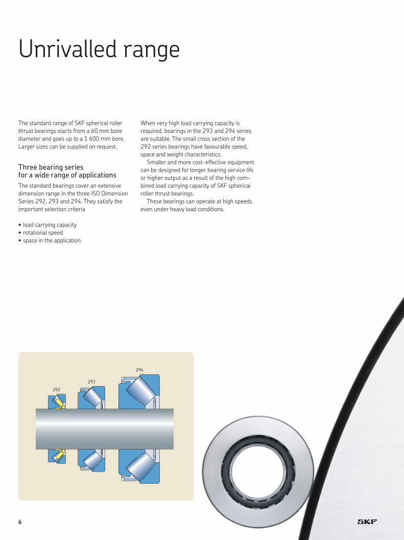
The standard range of SKF spherical roller thrust bearings starts from a 60 mm bore diameter and goes up to a 1 600 mm bore. Larger sizes can be supplied on request.
Three bearing series for a wide range of applicationsThe standard bearings cover an extensive dimension range in the three ISO Dimension Series 292, 293 and 294. They satisfy the important selection criteria
•loadcarryingcapacity•rotationalspeed•spaceintheapplication.
When very high load carrying capacity is required, bearings in the 293 and 294 series are suitable. The small cross section of the 292 series bear ings have favourable speed, space and weight characteristics.
Smaller and more cost-effective equipment can be designed for longer bearing service life or higher output as a result of the high com-bined load carrying capacity of SKF spherical roller thrust bearings.
These bearings can operate at high speeds even under heavy load conditions.
292
293
294
6
A
7
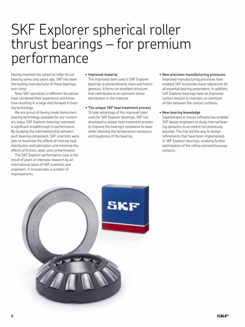
SKF Explorer spherical roller thrust bearings – for premium performanceHaving invented the spherical roller thrust bearing some sixty years ago, SKF has been the leading manufacturer of these bearings ever since.
Now, SKF specialists in different dis cip lines have combined their experience and know-how resulting in a large step forward in bear-ing technology.
We are proud of having made tomor row’s bear ing technology available for our custom-ers today. SKF Explorer bearings repre sent a significant breakthrough in performance. By studying the interrelation ship between each bear ing component, SKF scientists were able to maximize the effects of internal load distribution and lubrication and minimize the effects of friction, wear, and contamination.
The SKF Explorer performance class is the result of years of intensive re search by an international team of SKF scientists and engin eers. It incorporates a number of improve ments.
•Improved materialThe improved steel used in SKF Explorer bearings is extraordinarily clean and homo-geneous. It forms an excellent structure that contributes to an optimum stress distribution in the material.
•TheuniqueSKFheattreatmentprocessTo take advantage of the improved steel used for SKF Explorer bearings, SKF has developed a unique heat treatment process to improve the bearing’s resistance to wear while retaining the temperature resistance and toughness of the bearing.
•NewprecisionmanufacturingprocessesImproved manufacturing processes have enabled SKF to provide closer tolerances for all essential bearing parameters. In addition, SKF Explorer bearings have an improved surface texture to maintain an optimum oil film between the contact surfaces.
•NewbearingknowledgeSophisticated in-house software has en abled SKF design engineers to study intern al bear-ing dynamics to an extent not pre viously possible. This has led the way to design refinements that have been implemented in SKF Explorer bearings, enabling further optimization of the rolling elem ent/raceway contacts.
8
The result: longer bearing service lifeAll these improvements contribute to a sig-nificant increase in bearing service life and reliability. This can best be shown through a calculation using the SKF rating life equation. The properties of SKF Explorer spherical roller thrust bearings are taken into con-sideration by
•increasedbasicdynamicloadratingsand•betterresistancetocontamination, resulting
in an increased life modification factor aSKF.
AvailabilityThe popular small and medium size spherical roller thrust bearings in the 293 and 294 series are available as SKF Explorer bearings.
In the product table, the SKF Explorer bearing designations are printed in blue.
Product designationsSKF Explorer bearings have retained the designations of the earlier stand ard bearings, e.g. 29330 E. However, each bearing and its box are marked with the name “SKF EXPLORER”.
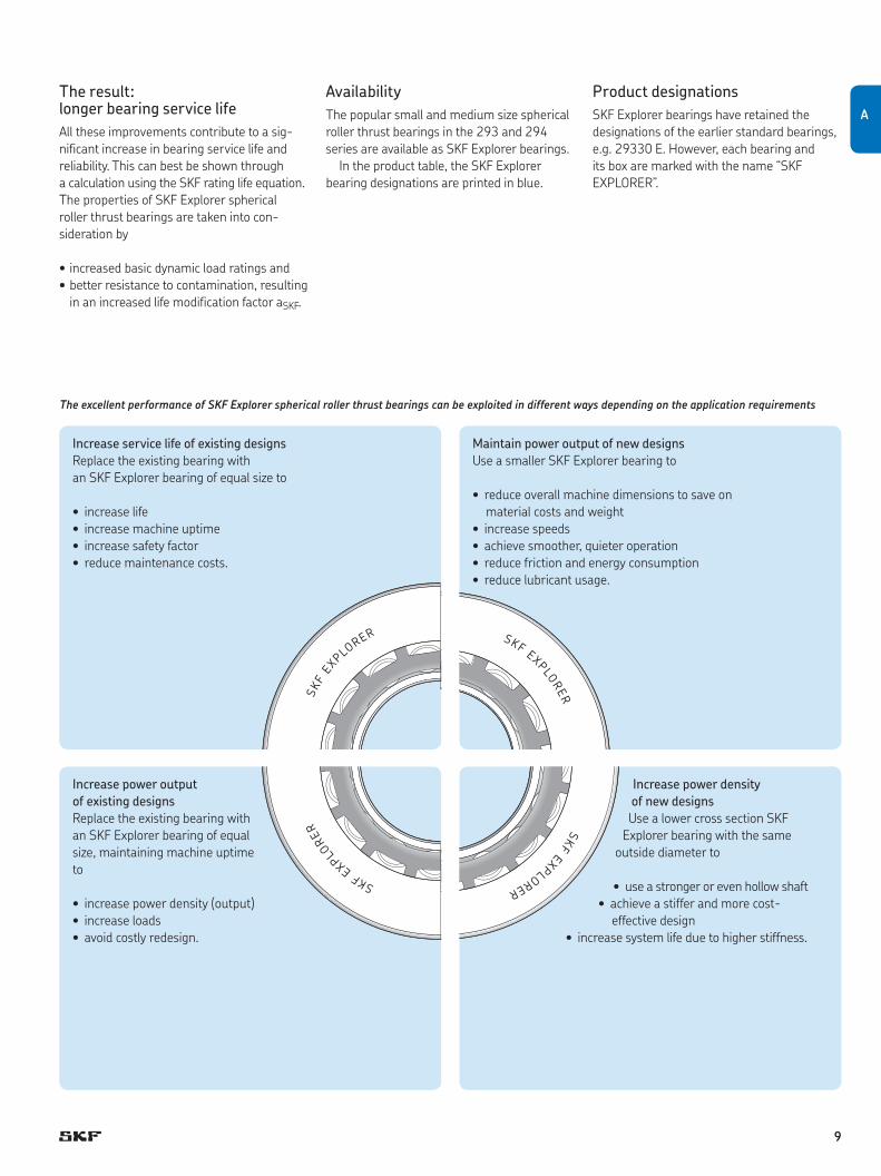
The excellent performance of SKF Explorer spherical roller thrust bearings can be exploited in different ways depending on the application requirements
Increase service life of existing designsReplacetheexistingbearingwith an SKF Explorer bearing of equal size to
• increaselife• increasemachineuptime• increasesafetyfactor•reducemaintenancecosts.
Maintain power output of new designsUse a smaller SKF Explorer bearing to
•reduceoverallmachinedimensionstosaveon material costs and weight
• increasespeeds•achievesmoother,quieteroperation•reducefrictionandenergyconsumption•reducelubricantusage.
Increase power density of new designsUse a lower cross section SKF
Explorer bearing with the same outside diameter to
•useastrongerorevenhollowshaft•achieveastifferandmorecost-
effective design• increasesystemlifeduetohigherstiffness.
Increase power output of existing designsReplacetheexistingbearingwithan SKF Explorer bearing of equal size, maintaining machine uptime to
• increasepowerdensity(output)• increaseloads•avoidcostlyredesign.
SKF
EXPLORER
SKF EXPLO
RER
SKF EXPLORERSKF EXPLORER
A
9
Where heavy combined loads must be accommodated
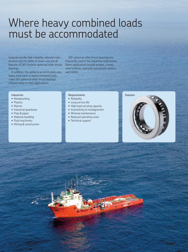
Long service life, high reliability, re duced main-ten ance and the ability to down-size are all features of SKF Explorer spherical roller thrust bearings.
In addition, the ability to accommodate very heavy axial loads or heavy combined loads make SKF spherical roller thrust bearings indispens able in many applications.
SKF spherical roller thrust bearings are frequently used in the industries listed below. Other applications include bridges, cranes, wind turbines, hydraulic and electric motors, and robots.
Industries•Metalworking•Plastics•Marine• Industrialgearboxes•Pulp&paper•Materialhandling•Fluidmachinery•Mining&construction
Requirements•Reliability•Longservicelife•Highloadcarryingcapacity• Insensitivitytomisalignment•Minimal maintenance•Reducedoperatingcosts•Technicalsupport
Solution
10

© G
reat
Lak
es G
roup
, Cle
vela
nd, O
hio
A
11

Selection of bearing size
Bearing lifeThe life-extending improvements em bo died in SKF Explorer spherical roller thrust bear-ings can best be understood using the SKF rating life method. This method constitutes an exten sion of the fatigue life theory developed by Lundberg and Palmgren and is better able to predict bearing life. The SKF rating life method was first presented in 1989. For roller bearings
Lnm = a1 aSKF L10
or
q C wLnm = a1 aSKF —
10/3
< P z
If the speed is constant, it is often preferable to calculate the life ex pressed in operating hours using
1 000 000 qCwLnmh = a1 aSKF ————— —
10/3
60 n <P z
whereLnm = SKF rating life (at 100 – n1) %
reliability), millions of revolutionsLnmh = SKF rating life (at 100 – n1) %
reliability), operating hoursL10 = basic rating life (at 90 % reli ability),
millions of revolutionsa1 = life adjustment factor for reliability
(† table 1)aSKF = SKF life modification factor
(† diagram 1)C = basic dynamic load rating, kNP = equivalent dynamic bearing load, kNn = rotational speed, r/min
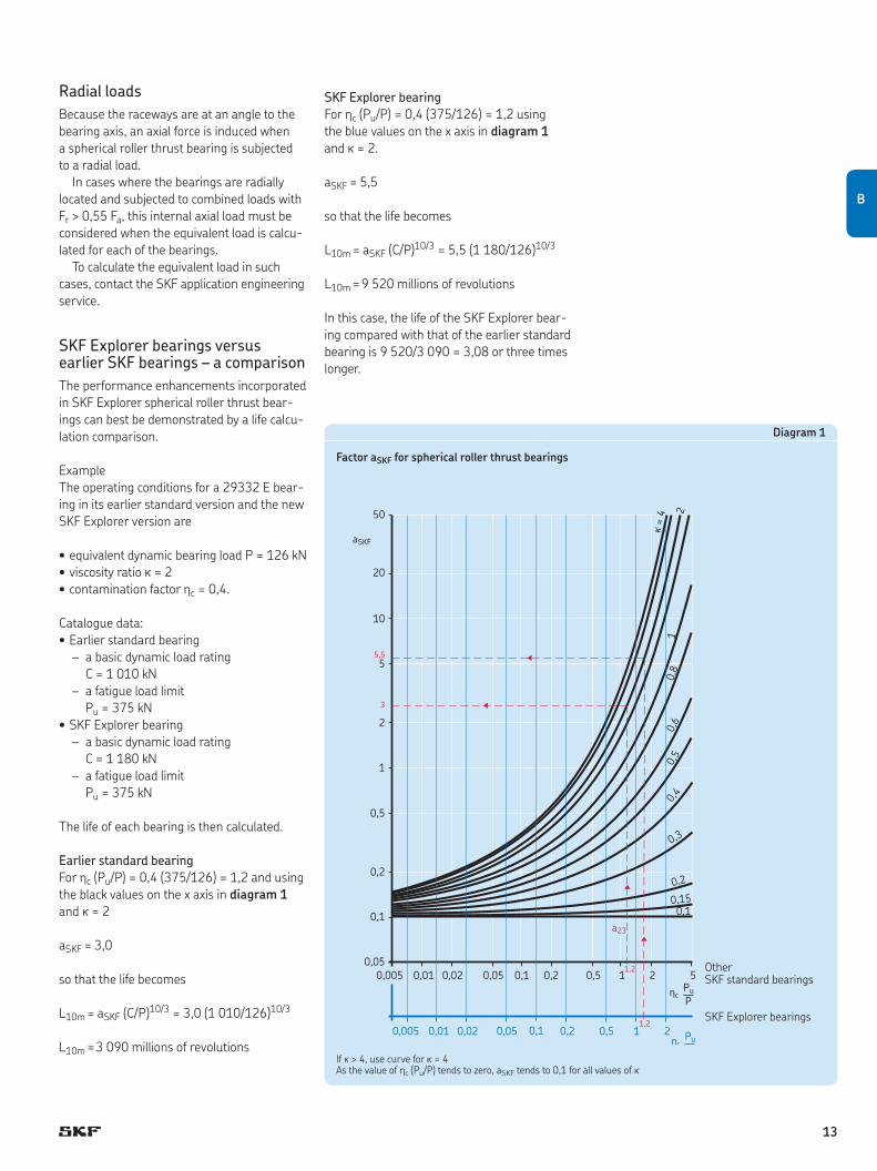
The aSKF factorThe aSKF factor represents a very complex relationship between load, contamination and lubrication. Values for aSKF can be obtained from diagram 1 for differ ent values of hc (Pu/P) and k, where
hc = factor for contamination levelPu = bearing fatigue load limitP = equivalent dynamic bearing loadk = lubricant viscosity ratio
Diagram 1 is valid for lubricants with out EP additives. For non-SKF Explorer spherical roller thrust bearings, the values in black colour on the x axis should be used. For SKF Explorer bearings, the values in blue should be used. For SKF Explorer spherical roller thrust bearings it has been found appropriate to multiply hc (Pu/P) by a factor of 1,4 as an expression of the life extending refinements of these bearings, and the blue values corres-pond to this.
Detailed information is provided in the SKF General Catalogue and the SKF Interactive Engin eering Catalogue online at www.skf.com.
Equivalent dynamic bearing loadNormally a spherical roller thrust bear ing is arranged so that runouts in the bearing arrangement do not affect the load distribution in the bearing. For dynamically loaded spherical roller thrust bearings arranged under these conditions, provided Fr ≤ 0,55 Fa
P = 0,88 (Fa + 1,2 Fr)
When runouts in the bearing arrangement affect the load distribution in the spherical roller thrust bearing, provided Fr ≤ 0,55 Fa
P = Fa + 1,2 Fr
If Fr > 0,55 Fa, contact the SKF application engineering service.
Equivalent static bearing loadFor statically loaded spherical roller thrust bearings, provided Fr ≤ 0,55 Fa,
P0 = Fa + 2,7 Fr
If Fr > 0,55 Fa, contact the SKF application engineering service.
Bearing arrangements with axial loads acting in both directionsThe information above is valid for sin gle bear-ings but when the thrust load changes direc-tion, it is necessary to use two bearings, most often two spherical roller thrust bearings mount ed in a back-to-back or face-to-face arrangement. In some cases the radial load is accommodated by a separate radial bearing and the spherical roller thrust bearings are radially free and spring preloaded († fig. 4, page 15) to provide that the bearing that is axially unloaded is subjected to the minimum requisite thrust load († section “Bearing data –general”,startingonpage 34).
In such cases the equivalent bear ing load is calculated for each bearing separately as for single bearings. The life of the pair is then calculated as a system life.
1) The factor n represents the failure probability, i.e. the difference between the requisite reliability and 100 %
Table 1
Values for the life adjustment factor a1
Reliability Failure SKF Factor% probability rating life a1 n Lnm %
90 10 L10m 195 5 L5m 0,6296 4 L4m 0,53
97 3 L3m 0,4498 2 L2m 0,3399 1 L1m 0,21
12
Radial loadsBecause the raceways are at an angle to the bearing axis, an axial force is induced when a spherical roller thrust bearing is subjected to a radial load.
In cases where the bearings are radially located and subjected to combined loads with Fr > 0,55 Fa, this intern al axial load must be considered when the equivalent load is calcu-lated for each of the bearings.
To calculate the equivalent load in such cases, contact the SKF application engi n eering service.
SKF Explorer bearings versus earlier SKF bearings – a comparisonThe performance enhancements incorp orated in SKF Explorer spherical roller thrust bear-ings can best be demonstrated by a life calcu-lation comparison.
ExampleThe operating conditions for a 29332 E bear-ing in its earlier standard version and the new SKF Explorer version are
•equivalentdynamicbearingloadP = 126 kN•viscosityratiok = 2•contaminationfactorhc = 0,4.
Catalogue data:•Earlierstandardbearing – a basic dynamic load rating C = 1 010 kN – a fatigue load limit Pu = 375 kN •SKFExplorerbearing – a basic dynamic load rating C = 1 180 kN – a fatigue load limit Pu = 375 kN
The life of each bearing is then calculated.
Earlier standard bearingFor hc (Pu/P) = 0,4 (375/126) = 1,2 and using the black values on the x axis in diagram 1 and k = 2
aSKF = 3,0
so that the life becomes
L10m = aSKF (C/P)10/3 = 3,0 (1 010/126)10/3
L10m = 3 090 millions of revolutions
SKF Explorer bearingFor hc (Pu/P) = 0,4 (375/126) = 1,2 using the blue values on the x axis in diagram 1 and k = 2.
aSKF = 5,5
so that the life becomes
L10m = aSKF (C/P)10/3 = 5,5 (1 180/126)10/3
L10m = 9 520 millions of revolutions
In this case, the life of the SKF Explorer bear-ing compared with that of the earlier standard bearing is 9 520/3 090 = 3,08 or three times longer.
If k > 4, use curve for k = 4As the value of hc (Pu/P) tends to zero, aSKF tends to 0,1 for all values of k
0,005 0,01 0,02 0,050,05
0,1
0,1
0,2
0,2
0,5
0,5
1
1
2
2
5
10
20
50
5
aSKF
hcPuP––
hcPuP––
10,
5
0,1
0,4
0,3
0,15
0,8
k =
4
0,2
0,6
2
0,005 0,01 0,02 0,05 0,1 0,2 0,5 1 2
a23
1,2
1,2
5,5
3
OtherSKF standard bearings
SKF Explorer bearings
Diagram 1
Factor aSKF for spherical roller thrust bearings
B
13
Design of bearing arrangements
Single direction thrust bearing arrangementsA single spherical roller thrust bearing can sup-port a shaft together with a radial bearing when
•thethrustloadisinonedirectiononly, and•thetotalaxialloadonthebearingisnever
lower than the requisite min imum axial load († page 35).
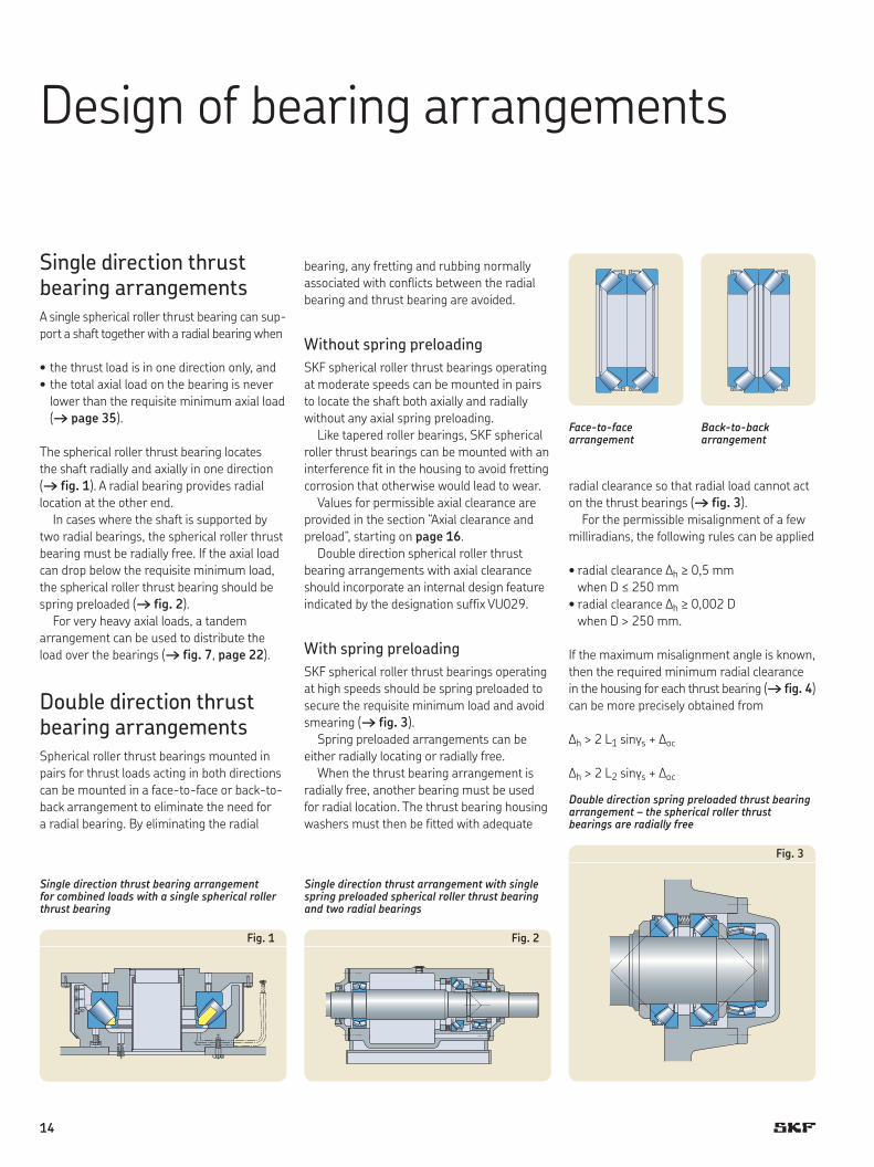
The spherical roller thrust bearing locates the shaft radially and axially in one direction († fig. 1). A radial bear ing provides radial location at the other end.
In cases where the shaft is support ed by two radial bearings, the spher ical roller thrust bearing must be radial ly free. If the axial load can drop below the requisite minimum load, the spherical roller thrust bearing should be spring preloaded († fig. 2).
For very heavy axial loads, a tandem arrangement can be used to distribute the load over the bearings († fig. 7, page 22).
Double direction thrust bearing arrangementsSpherical roller thrust bearings mounted in pairs for thrust loads acting in both directions can be mounted in a face-to-face or back-to-back arrangement to eliminate the need for a radial bearing. By eliminating the radial
bearing, any fretting and rubbing normally associated with conflicts between the radial bearing and thrust bearing are avoided.
Without spring preloadingSKF spherical roller thrust bearings operating at moderate speeds can be mounted in pairs to locate the shaft both axially and radially without any axial spring preloading.
Like tapered roller bearings, SKF spherical roller thrust bearings can be mounted with an interference fit in the housing to avoid fretting corrosion that otherwise would lead to wear.
Values for permissible axial clearance are provided in the section “Axial clearance and preload”,startingonpage 16.
Double direction spherical roller thrust bearing arrangements with axial clearance should incorporate an internal design feature indicated by the designation suffix VU029.
With spring preloadingSKF spherical roller thrust bearings operating at high speeds should be spring preloaded to secure the requisite minimum load and avoid smearing († fig. 3).
Spring preloaded arrangements can be either radially locating or radially free.
When the thrust bearing arrangement is radially free, another bearing must be used for radial location. The thrust bearing housing washers must then be fitted with adequate
radial clearance so that radial load cannot act on the thrust bearings († fig. 3).
For the permissible misalignment of a few milliradians, the following rules can be applied
•radial clearance ∆h ≥ 0,5 mm when D ≤ 250 mm
•radial clearance ∆h ≥ 0,002 D when D > 250 mm.
If the maximum misalignment angle is known, then the required minimum radial clearance in the housing for each thrust bearing († fig. 4) can be more precisely obtained from
∆h > 2 L1 sings + ∆oc
∆h > 2 L2 sings + ∆oc
Single direction thrust bearing arrangement for combined loads with a single spherical roller thrust bearing
Single direction thrust arrangement with single spring preloaded spherical roller thrust bearing and two radial bearings
Face-to-face arrangement
Fig. 3
Fig. 2
Back-to-back arrangement
Double direction spring preloaded thrust bearing arrangement – the spherical roller thrust bearings are radially free
Fig. 1
14
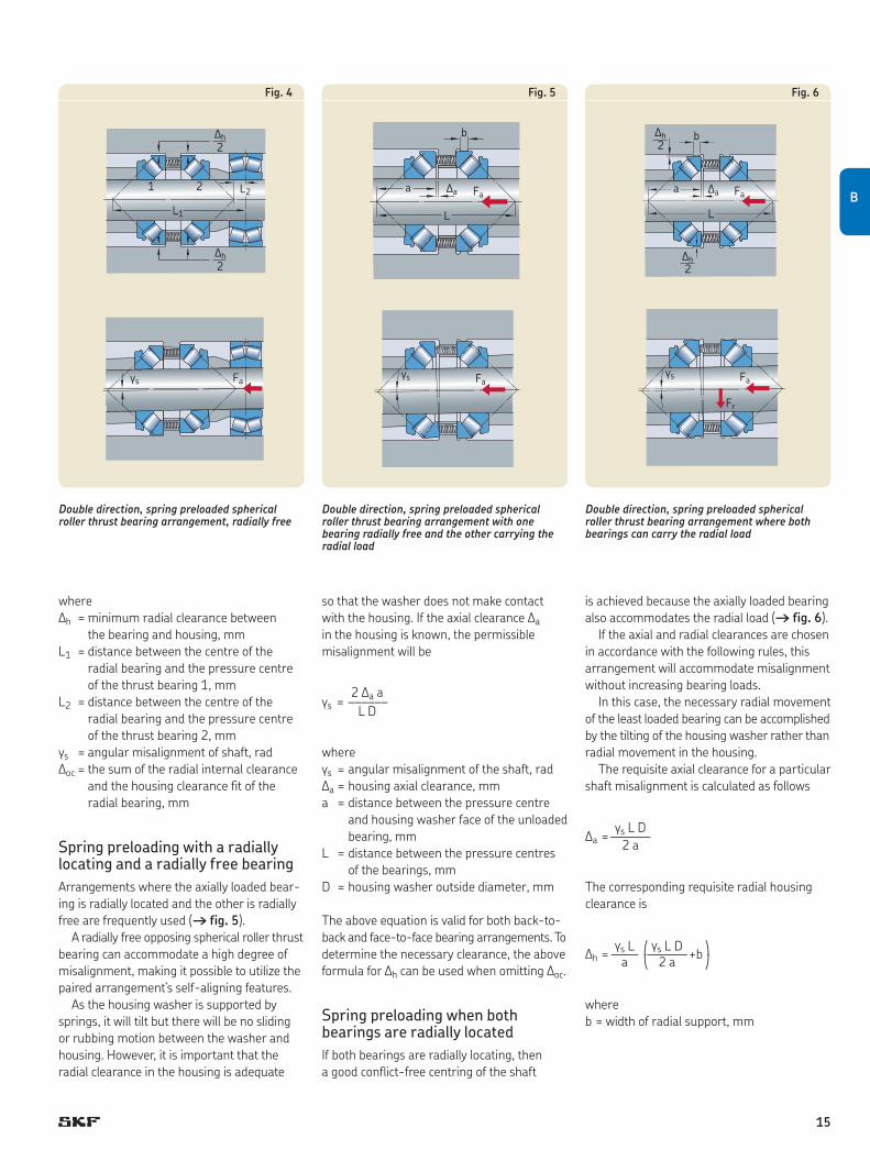
where∆h = minimum radial clearance be tween
the bearing and housing, mmL1 = distance between the centre of the
radial bearing and the pres sure centre of the thrust bearing 1, mm
L2 = distance between the centre of the radial bearing and the pres sure centre of the thrust bearing 2, mm
gs = angular misalignment of shaft, rad∆oc = the sum of the radial internal clear ance
and the housing clearance fit of the radial bearing, mm
Spring preloading with a radially locating and a radially free bearingArrangements where the axially load ed bear-ing is radially located and the other is radially free are frequently used († fig. 5).
A radially free opposing spherical roller thrust bearing can accommodate a high de gree of misalignment, making it possible to utilize the paired arrangement’s self-aligning features.
As the housing washer is supported by springs, it will tilt but there will be no sliding or rubbing motion between the washer and housing. However, it is important that the radial clearance in the housing is adequate
so that the washer does not make contact with the housing. If the axial clearance ∆a in the housing is known, the permissible misalignment will be
2 ∆a ags = –––––– L D
wheregs = angular misalignment of the shaft, rad∆a = housing axial clearance, mma = distance between the pressure centre
and housing washer face of the unloaded bearing, mm
L = distance between the pressure centres of the bearings, mm
D = housing washer outside diameter, mm
The above equation is valid for both back-to-back and face-to-face bearing arrangements. To determine the necessary clearance, the above formula for ∆h can be used when omitting ∆oc.
Spring preloading when both bearings are radially locatedIf both bearings are radially locating, then a good conflict-free centring of the shaft
is achieved because the axially loaded bearing also accommodates the radial load († fig. 6).
If the axial and radial clearances are chosen in accordance with the following rules, this arrangement will accommodate misalignment without increasing bearing loads.
In this case, the necessary radial movement of the least loaded bearing can be accomplished by the tilting of the housing washer rather than radial movement in the housing.
The requisite axial clearance for a particular shaft misalignment is calculated as follows
gs L DDa = ——— 2 a
The corresponding requisite radial housing clearance is
gs L q gs L D wDh = —— ———+b a < 2 a z
whereb = width of radial support, mm
Double direction, spring preloaded spherical roller thrust bearing arrangement, radially free
Double direction, spring preloaded spherical roller thrust bearing arrangement with one bearing radially free and the other carrying the radial load
Double direction, spring preloaded spherical roller thrust bearing arrangement where both bearings can carry the radial load
Fig. 4 Fig. 5 Fig. 6
L2
L1
1 2
2
2
Dh
Dh
Fags
L
Faa
b
Da
L
Faa
b2
2Dh
Dh
Da
gs Fags Fa
Fr
B
15
Axial clearance and preloadDepending on the application, the spherical roller thrust bearings in an arrangement can have an operational axial clearance or preload.
When a vertical application incorp orates a single spherical roller thrust bear ing, the load from the mass of the shaft acts as a preload on the spherical roller thrust bearing to locate the shaft radially and axially in one direction († fig. 1, page 14).
The radial bearing at the other end of the shaft must have a certain axial freedom to be able to accommodate thermal expansion and contraction of the shaft.
In applications where the shaft is supported by two radial bearings, the spherical roller thrust bearing must be mounted radially free. If the thrust load can drop below the requisite mini mum load, the bearing should be spring preloaded († fig. 2, page 14).
Axial clearanceSince a spherical roller thrust bearing is separ-able, the axial clearance can only be obtained after mounting and is determined by adjust-ing the bearing against a second bearing that provides location in the other direction.
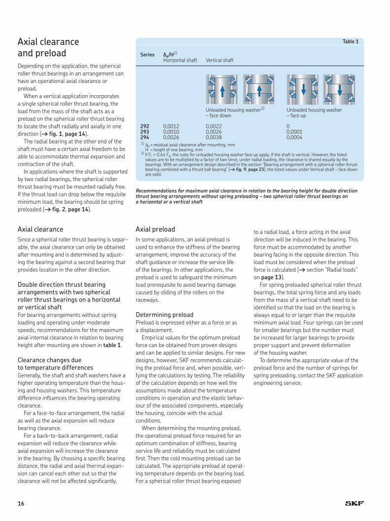
Double direction thrust bearing arrangements with two spherical roller thrust bearings on a horizontal or vertical shaftFor bearing arrangements without spring loading and operating under moderate speeds, recommendations for the maximum axial internal clearance in relation to bearing height after mounting are shown in table 1.
Clearance changes due to temperature differencesGenerally, the shaft and shaft washers have a higher operating temperature than the hous-ing and housing washers. This temperature difference influences the bearing operating clearance.
For a face-to-face arrangement, the radial as well as the axial expansion will reduce bearing clearance.
For a back-to-back arrangement, radial expansion will reduce the clearance while axial expansion will increase the clearance in the bearing. By choosing a specific bearing distance, the radial and axial thermal expan-sion can cancel each other out so that the clearance will not be affected significantly.
Axial preloadIn some applications, an axial preload is used to enhance the stiffness of the bearing arrange ment, improve the accuracy of the shaft guidance or increase the service life of the bearings. In other applications, the preload is used to safeguard the minimum load prerequisite to avoid bearing damage caused by sliding of the rollers on the raceways.
Determining preloadPreload is expressed either as a force or as a displacement.
Empirical values for the optimum preload force can be obtained from proven designs and can be applied to similar designs. For new designs, however, SKF recommends calculat-ing the preload force and, when possible, veri-fying the calculations by testing. The reliability of the calculation depends on how well the assumptions made about the temperature conditions in operation and the elastic behav-iour of the associated components, especially the housing, coincide with the actual conditions.
When determining the mounting preload, the operational preload force required for an optimum combination of stiffness, bearing service life and reliability must be calculated first. Then the cold mounting preload can be calculated. The appropriate preload at operat-ing temperature depends on the bearing load. For a spherical roller thrust bear ing exposed
to a radial load, a force acting in the axial direction will be induced in the bearing. This force must be accommodated by another bearing facing in the opposite direction. This load must be considered when the preload force is calculated (†section“Radialloads”on page 13).
For spring preloaded spherical roller thrust bearings, the total spring force and any loads from the mass of a vertical shaft need to be identified so that the load on the bear ing is always equal to or larger than the requisite minimum axial load. Four springs can be used for smaller bearings but the number must be increased for larger bearings to provide proper support and prevent deformation of the housing washer.
To determine the appropriate value of the preload force and the num ber of springs for spring preloading, contact the SKF application engi neering service.
Recommendations for maximum axial clearance in relation to the bearing height for double direction thrust bearing arrangements without spring preloading – two spherical roller thrust bearings on a horizontal or a vertical shaft
Series ∆a/H1)
Horizontal shaft Vertical shaft
292 0,0012 0,0022 0293 0,0010 0,0026 0,0001294 0,0026 0,0038 0,00041) ∆a = residual axial clearance after mounting, mm H = height of one bearing, mm2) If Fr > 0,64 Fa, the rules for unloaded housing washer face up apply, if the shaft is vertical. However, the listed
values are to be multiplied by a factor of two since, under radial loading, the clearance is shared equally by the bearings. With an arrangement design described in the section “Bearing arrangement with a spherical roller thrust bearingcombinedwithathrustballbearing”(† fig. 9, page 23), the listed values under Vertical shaft – face down are valid.
Table 1
Unloaded housing washer2)
– face downUnloaded housing washer– face up
16

Setting clearance and preloadIn face-to-face arrangements, the clearance and preload is set by adjusting the housing washers, which in most cases have a clear-ance fit and are therefore easy to move. The required position is obtained by placing shims between the housing and cover.
For back-to-back arrangements, the shaft washer, which generally has an inter ference fit, can be difficult to move into position. Here, use of the SKF oil injection method can facili-tate the adjustment.
In case of preload, the oil injection method, in combination with an HMV .. E type SKF hydraulic nut, can be used († fig. 7). When the washer has been heat mounted close to its correct position, the preload force is applied to the shaft washer by means of a specific oil pressure in the hydraulic nut, while oil is injected between the washer and shaft. This pushes the washer into the correct position. The preload from the hydraulic nut must be maintained until the oil injection pressure has been released and the washer has obtained a full interference fit with the shaft.
However, to use the oil injection method, the shaft needs to be pre pared with the necessary ducts and grooves (†section“Dismounting”,starting on page 30).
Setting the required preload using the oil injection method and an SKF hydraulic nut
Fig. 7
B
17

High-speed bearing arrangementsSKF spherical roller thrust bearings have a built-in capacity for high speed. With certain modifications to the intern al design and with special precautions related to lubrication, cooling and preload, it is possible to operate the bear ings at speeds up to three times greater than the catalogue refer ence speed (approximately one and a half times the limit-ing speed).
A bearing arrangement in a disc refiner for very high speed is shown in fig. 8.
In this application, a very heavy axial load is shared equally by two spherical roller thrust bearings mounted in tandem and preload applied by two hydraulic pistons. Prior to designing or operating any machine at speeds higher than the thermal reference speed, consult the SKF application engineering service.
Low-speed bearing arrangementsIn applications such as vertical air preheaters and extruders, speeds can be as low as 0,5 to 5 r/min while loads can be as heavy as P = 0,1 C0. High viscosity oils with addi t ives have proven to be effective for these types of applications. For additional information, contact the SKF application engineering service.
Low speed applications such as bridge and crane pivots are consid e r ed to be static appli-cations and the bear ings should be calculated with a static safety factor of s0 ≈ 4 or greater.
Stiffness
Some machines require stiffer bearing arrange ments than others. To meet those varied requirements, SKF spher i cal roller thrust bearings can be ar ranged for different levels of stiffness.
In back-to-back arrangements, the pres-sure centres of the bearings will be far apart to provide a very stiff arrangement that accommodates bend ing moments as well as axial and radial loads († fig. 9).
The face-to-face arrangement is not so stiff due to the shorter distance be tween the pressure centres. How ever, it is equally stiff for axial load and radial load respectively († fig. 10).
In face-to-face arrangements, the bearings can be placed so that their pressure centres coincide and the whole arrangement will be self-aligning, but with equal stiffness in both the axial and radial direction.
Design of associated components
Support of bearing washersTo optimize bearing performance under heavy axial loads, it is vital that the bear ing has sup-ports strong enough to prevent deformation of the bearing washers.
The abutment dimensions da min and Da max quoted in the product table, starting on page 36, apply for axial bearing loads Fa ≤ 0,1 C0.
If the bearings are subjected to heavier loads, it may be necessary for the bearing washers to be supported across their entire width (da = d1 and Da = D1). At heavy loads, P > 0,1 C0, the shaft washer bore must be fully supported by the shaft, preferably by an interfer ence fit. Even the housing washer should be radially supported († fig. 11).
For further information about dimensioning of washer supports, contact the SKF application engineering service.
SKF spherical roller thrust bearing arrangement in a high-speed disc refiner, lubricated with circulating oil
Back-to-back arrangements provide very high stiffness Face-to-face arrangements provide high stiffness
Fig. 8 Fig. 9 Fig. 10
18
Seals
The service life of a bearing depends to a large extent on the effectiveness of the seals. Seals prevent the entry of contaminants while retaining the lubricant.
The selection of a seal type depends on the operating conditions and environmental con-siderations such as
•thetypeoflubricant•the sliding velocity of the sealing surfaces•averticalorhorizontalshaft•thedegreeofmisalignment•thetypeofcontamination•thermalconditions.
Detailed information about selecting the seal type can be found in the SKF catalogue “Industrialshaftseals”.
Seals for grease lubricationLubricating greases are relatively easy to retain in the bear ing arrangement. As a result, the demands on seals are generally moderate.
SKF radial seals without a garter spring, HM and HMA types, are suit able for low sliding speeds. The seals should be arranged so the lip faces the bearing. V-rings or spring loaded radialseals,e.g.CRW1design,areequallysuitable for retaining grease.
If frequent relubrication is required, the lip of at least one of the seals should be arranged away from the grease so that excess grease can escape via this lip.
More information about sealing arrange-ments can be found in the section “Grease lubrication”,startingonpage 26.
Seals for oil lubricationLubricating oils are generally more difficult to retain in a bearing arrangement than greases. Therefore, spring loaded radial seals are used almost exclus ively, e.g. SKFsealsoftheCRW1,CRWH1,HMS4orHDS3designs.Normally,CRW1radialsealswithahydro-
dynamically formed seal lip, called SKF WAVE, are adequate († fig. 12). The SKF WAVE seal lip has a sinusoid ally formed edge which induces a pumping action to the inside as well as the outside, irrespective of the shaft’s direction of rotation.
Due to their internal design, spher ical roller thrust bearings create a pumping action which should be considered when selecting seals († section “Lubrication and mainten-ance”,startingonpage 24).
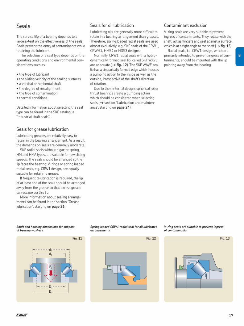
Contaminant exclusionV-ring seals are very suitable to prevent ingress of contaminants. They rotate with the shaft, act as flingers and seal against a surface, which is at a right angle to the shaft († fig. 13).Radialseals,i.e.CRW1design,whichare
primarily intended to prevent ingress of con -ta minants, should be mounted with the lip pointing away from the bearing.
Fa
D1
Da
da
d1
Shaft and housing dimensions for support of bearing washers
Spring loaded CRW1 radial seal for oil lubricated arrangements
V-ring seals are suitable to prevent ingress of contaminants
Fig. 11 Fig. 12 Fig. 13
B
19
Typical bearing arrangements
To fully utilize the features of spherical roller thrust bearings, they must be properly applied. One of the advantages of spherical roller thrust bearings is that they can accommodate radial as well as axial loads. This is why a sin-gle spherical roller thrust bearing is fre quently used in some applications to accommodate combined loads.
Correctly applied, the bearing will then work smoothly as long as Fr ≤ 0,55 Fa. If the bearing must accommodate a heavy radial load, Fr > 0,55 Fa, the bearing should be com-bined with another bearing. This second bearing can be a spherical roller thrust bear-ing, but other bearing types can be used. In applications where a spherical roller thrust bearing is mounted radially free and axial loads may not meet requisite minimums, springs must be used to preload the bearing.
Some typical bearing arrangements incorp-orating spherical roller thrust bear ings are shown below.
Single direction thrust bearing arrangements
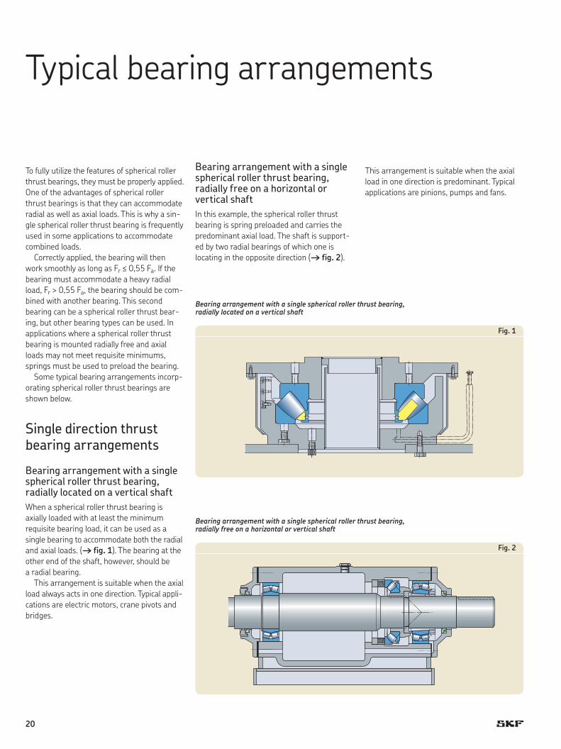
Bearing arrangement with a single spherical roller thrust bearing, radially located on a vertical shaftWhen a spherical roller thrust bearing is axial ly loaded with at least the min imum requisite bearing load, it can be used as a single bearing to accommodate both the radial and axial loads. († fig. 1). The bearing at the other end of the shaft, however, should be a radial bearing.
This arrangement is suitable when the axial load always acts in one direction. Typical app li-cations are electric motors, crane pivots and bridges.
Bearing arrangement with a single spherical roller thrust bearing, radially free on a horizon tal or vertical shaftIn this example, the spherical roller thrust bearing is spring preloaded and carries the predominant axial load. The shaft is support-ed by two radial bearings of which one is locating in the opposite direction († fig. 2).
Bearing arrangement with a single spherical roller thrust bearing, radially located on a vertical shaft
Bearing arrangement with a single spherical roller thrust bearing, radially free on a horizontal or vertical shaft
This ar range ment is suitable when the axial load in one direction is predominant. Typical applications are pinions, pumps and fans.
Fig. 1
Fig. 2
20
Double direction thrust bearing arrangements
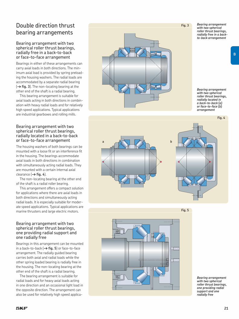
Bearing arrangement with two spherical roller thrust bearings, radially free in a back-to-back or face-to-face arrangementBearings in either of these arrangements can carry axial loads in both directions. The min-imum axial load is provided by spring preload-ing the housing wash ers. The radial loads are accommod ated by a separate radial bearing († fig. 3). The non-locating bearing at the other end of the shaft is a radial bearing.
This bearing arrangement is suitable for axial loads acting in both directions in combin-ation with heavy radial loads and for relatively high speed applications. Typical applications are industrial gearboxes and rolling mills.
Bearing arrangement with two spherical roller thrust bearings, radially located in a back-to-back or face-to-face arrangementThe housing washers of both bearings can be mounted with a loose fit or an inter ference fit in the housing. The bear ings accommodate axial loads in both directions in combination with simul taneously acting radial loads. They are mounted with a certain internal axial clearance († fig. 4).
The non-locating bearing at the other end of the shaft is a radial roller bearing.
This arrangement offers a compact solution for applications where there are axial loads in both directions and simultan eously acting radial loads. It is especially suitable for moder-ate speed applications. Typical applications are marine thrusters and large electric motors.
Bearing arrangement with two spherical roller thrust bearings, one providing radial support and one radially freeBearings in this arrangement can be mount ed in a back-to-back († fig. 5) or face-to-face arrangement. The radially guided bear ing carries both axial and radial loads while the other spring loaded bearing is radially free in the housing. The non-locat ing bearing at the other end of the shaft is a radial bear ing.
The bearing arrangement is suitable for radial loads and for heavy axial loads acting in one direction and an occasional light load in the opposite direction. The ar rangement can also be used for relatively high speed applica-
Bearing arrangement with two spherical roller thrust bearings, radially free in a back-to-back arrangement
Bearing arrangement with two spherical roller thrust bearings, one providing radial support and one radially free
Bearing arrangement with two spherical roller thrust bearings, radially located in a back-to-back (a) or face-to-face (b) arrangement
a b
Fig. 4
Fig. 3
Fig. 5
B
21

tions. Typical arrangements are disc refiners and small horizontal water turbines.
Bearing arrangement with a spherical roller thrust bearing combined with a spherical roller bearing – common pressure centreThe bearings in this arrangement are mount-ed to achieve a common pres sure centre, which makes the arrangement self-aligning. The spher ical roller thrust bearing is radially free and accommodates axial loads only. Radialloadsareaccommodatedbythespher-ical roller bearing. The minimum axial load on the spherical roller thrust bearing is achieved by spring loading the hous ing washer († fig. 6). The non-locating bearing at the other end of the shaft is a radial roller bearing.
This bearing arrangement is suitable for radial loads and heavy axial loads acting in one direction and an occasional light axial load in the opposite direction. This applies for low as well as high speed applications. Typical arrangements are propeller thrust bearing arrangements, waterjets and pumps.
Bearing arrangement with two spherical roller thrust bearings in tandem arrangementFor very heavy axial loads, two spherical roller thrust bearings mounted in tandem can be used to carry the predominant axial load. The load is equally shared by the two bearings by means of two hydraulic pistons. The spherical roller thrust bearings are radially free and the shaft is radially supported by two radial bearings.
Alternatively, one of the bearings in the tandem arrangement can be used for radial support as well, together with a third spher ical roller thrust bearing that provides shaft location in the other direction († fig. 7).
The arrangement is suitable when the axial load is very heavy in one direction. Typical ar range ments are spindle units and disc refiners.
Bearing arrangement with a spherical roller
thrust bearing combined with
a spherical roller bearing – common
pressure centre
Bearing arrangement with two spherical
roller thrust bearings in tandem
arrangement
Fig. 6
Fig. 7
22
Bearing arrangement with a spherical roller thrust bearing combined with a tapered roller bear ing
Bearing arrangement with a spherical roller thrust bearing combined with a thrust ball bearing
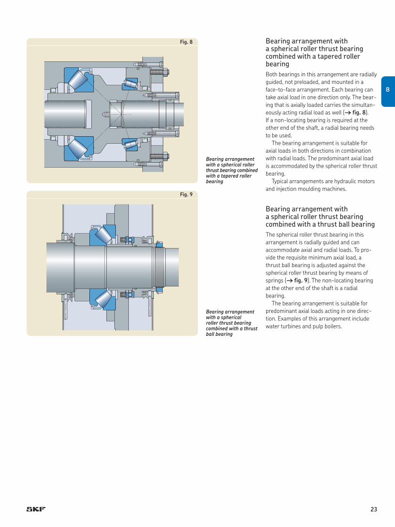
Bearing arrangement with a spherical roller thrust bearing combined with a tapered roller bear ingBoth bearings in this arrangement are radially guided, not preloaded, and mounted in a face-to-face arrangement. Each bearing can take axial load in one direction only. The bear-ing that is axially loaded carries the simultan-eously acting radial load as well († fig. 8). If a non-locating bearing is required at the other end of the shaft, a radial bearing needs to be used.
The bearing arrangement is suitable for axial loads in both directions in combination with radial loads. The predominant axial load is accom mo d ated by the spherical roller thrust bearing.
Typical arrangements are hyd raul ic motors and injection moulding machines.
Bearing arrangement with a spherical roller thrust bearing combined with a thrust ball bearingThe spherical roller thrust bearing in this arrangement is radially guided and can ac commodate axial and radial loads. To pro-vide the requisite minimum axial load, a thrust ball bear ing is adjusted against the spherical roller thrust bearing by means of springs († fig. 9). The non-locating bearing at the other end of the shaft is a radial bearing.
The bearing arrangement is suitable for predominant axial loads acting in one direc-tion. Examples of this arrange ment include water turbines and pulp boilers.
Fig. 8
Fig. 9
B
23
Lubrication and maintenance
LubricantsGenerally, lubrication with oil or grease con-taining EP additives is recommend ed for spherical roller thrust bear ings.
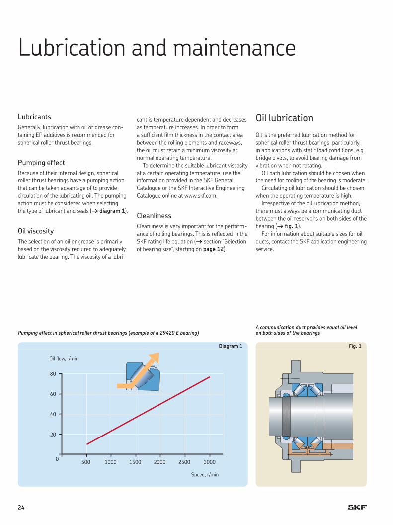
Pumping effectBecause of their internal design, spher ical roller thrust bearings have a pumping action that can be taken advantage of to provide circulation of the lubricating oil. The pump ing action must be considered when selecting the type of lubricant and seals († diagram 1).
Oil viscosityThe selection of an oil or grease is primarily based on the viscosity required to adequately lubricate the bearing. The viscosity of a lubri-
cant is tem perature dependent and decreases as temperature increases. In order to form a sufficient film thickness in the contact area between the rolling elements and raceways, the oil must retain a minimum viscosity at normal operating temperature.
To determine the suitable lubricant viscosity at a certain operating temperature, use the information provided in the SKF General Cata logue or the SKF Interactive Engineering Cata logue online at www.skf.com.
CleanlinessCleanliness is very important for the perform-ance of rolling bearings. This is reflected in the SKF rating life equation († section “Selection ofbearingsize”,startingon page 12).
Oil lubrication
Oil is the preferred lubrication method for spherical roller thrust bearings, particularly in applications with static load conditions, e.g. bridge pivots, to avoid bearing damage from vibration when not rotat ing.
Oil bath lubrication should be chosen when the need for cooling of the bearing is moderate.
Circulating oil lubrication should be chosen when the operating temperature is high.
Irrespective of the oil lubrication method, there must always be a com mun i cating duct between the oil reservoirs on both sides of the bearing († fig. 1).
For information about suitable sizes for oil ducts, contact the SKF application engineering service.
Speed, r/min
0
20
40
60
80
500 1000 1500 2000 2500 3000
Oil flow, l/min
Pumping effect in spherical roller thrust bearings (example of a 29420 E bearing)A communication duct provides equal oil level on both sides of the bearings
Fig. 1Diagram 1
24
Oil bath lubricationFor vertical shafts, oil bath lubrication is an appropriate choice. The pumping effect of the bearing can be used to force oil through the bearing.
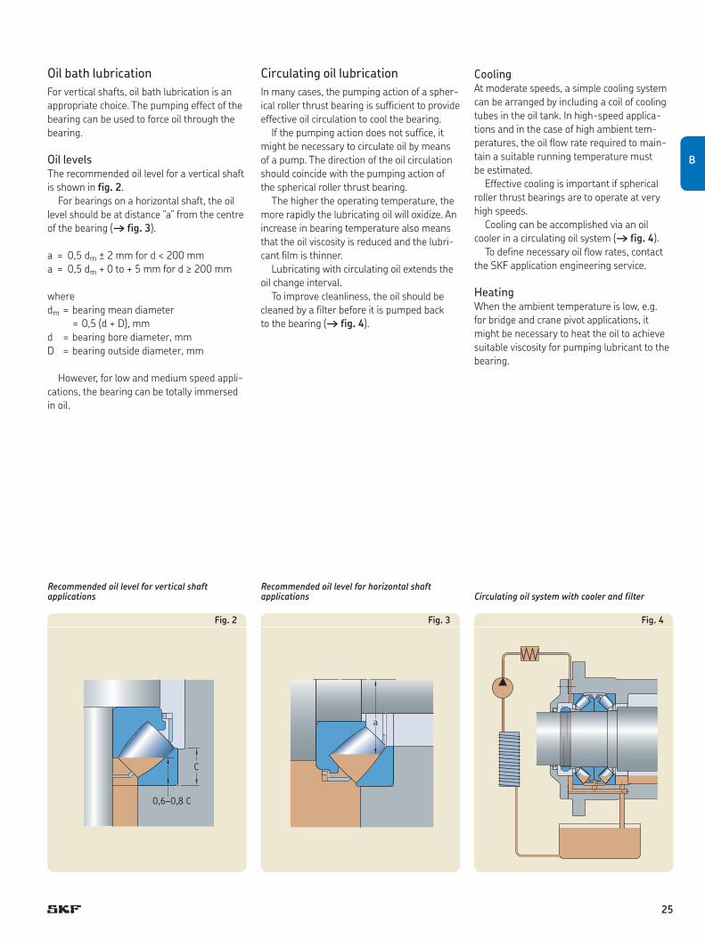
Oil levelsThe recommended oil level for a ver tical shaft is shown in fig. 2.
For bearings on a horizontal shaft, the oil levelshouldbeatdistance“a”fromthecentreof the bearing († fig. 3).
a = 0,5 dm ± 2 mm for d < 200 mma = 0,5 dm + 0 to + 5 mm for d ≥ 200 mm
wheredm = bearing mean diameter = 0,5 (d + D), mmd = bearing bore diameter, mmD = bearing outside diameter, mm
However, for low and medium speed appli-cations, the bearing can be totally immersed in oil.
0,6–0,8 C
C
Recommended oil level for vertical shaft applications
a
Recommended oil level for horizontal shaft applications Circulating oil system with cooler and filter
Circulating oil lubricationIn many cases, the pumping action of a spher-ical roller thrust bearing is suffi cient to provide effective oil circulation to cool the bearing.
If the pumping action does not suffice, it might be necessary to circulate oil by means of a pump. The direction of the oil circulation should coincide with the pumping action of the spherical roller thrust bear ing.
The higher the operating temperature, the more rapidly the lubricating oil will oxidize. An increase in bearing temperature also means that the oil viscosity is reduced and the lubri-cant film is thinner.
Lubricating with circulating oil ex tends the oil change interval.
To improve cleanliness, the oil should be cleaned by a filter before it is pumped back to the bearing († fig. 4).
CoolingAt moderate speeds, a simple cooling system can be arranged by including a coil of cooling tubes in the oil tank. In high-speed applica-tions and in the case of high ambient tem-peratures, the oil flow rate required to main-tain a suitable running temperature must be estimated.
Effective cooling is important if spher ical roller thrust bearings are to operate at very high speeds.
Cooling can be accomplished via an oil cooler in a circulating oil system († fig. 4).
To define necessary oil flow rates, contact the SKF application engineering service.
HeatingWhen the ambient temperature is low, e.g. for bridge and crane pivot applications, it might be necessary to heat the oil to achieve suitable viscosity for pumping lubricant to the bearing.
Fig. 2 Fig. 3 Fig. 4
B
25
Grease lubrication
When lubricating with grease, the roller end/flange contacts must be adequate ly supplied with lubricant. Depending on the application, this can best be done by completely filling the bearing and housing with grease before the initial start-up and then following up with a regular relubrication schedule.
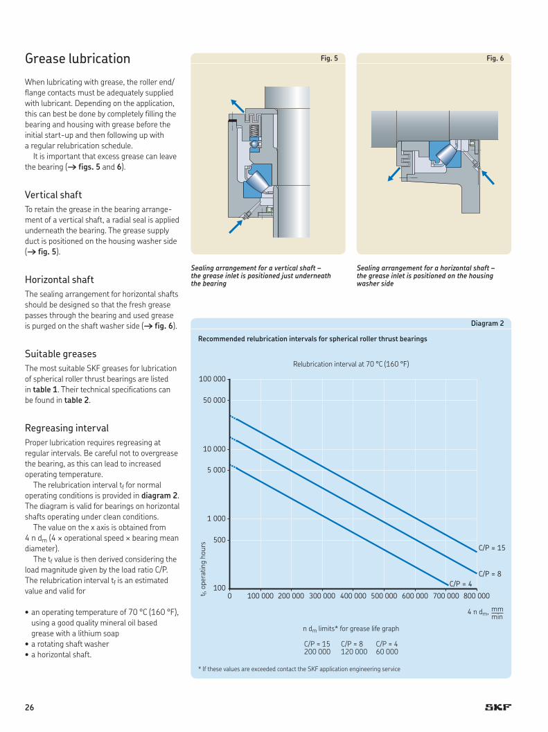
It is important that excess grease can leave the bearing († figs. 5 and 6).
Vertical shaftTo retain the grease in the bearing arrange-ment of a vertical shaft, a radial seal is applied underneath the bearing. The grease supply duct is positioned on the housing washer side († fig. 5).
Horizontal shaftThe sealing arrangement for horizontal shafts should be designed so that the fresh grease passes through the bear ing and used grease is purged on the shaft washer side († fig. 6).
Suitable greasesThe most suitable SKF greases for lubrication of spherical roller thrust bearings are listed in table 1. Their technical specifications can be found in table 2.
Regreasing intervalProper lubrication requires regreasing at regular intervals. Be careful not to overgrease the bearing, as this can lead to increased operating temperature.
The relubrication interval tf for normal operating conditions is provided in diagram 2. The diagram is valid for bearings on horizontal shafts oper ating under clean conditions.
The value on the x axis is obtained from 4 n dm (4 ¥ operational speed ¥ bear ing mean diameter).
The tf value is then derived considering the load magnitude given by the load ratio C/P. The relubrication interval tf is an estimated value and valid for
•an operating temperature of 70 °C (160 °F), using a good quality mineral oil based grease with a lithium soap
•a rotating shaft washer•a horizontal shaft.
Sealing arrangement for a vertical shaft – the grease inlet is positioned just underneath the bearing
Sealing arrangement for a horizontal shaft – the grease inlet is positioned on the housing washer side
0 100
500
1 000
5 000
10 000
50 000
100 000
100 000 200 000 300 000 400 000 500 000 700 000600 000 800 000
C/P = 15
C/P = 4C/P = 8
Relubricationintervalat70°C(160°F)
Diagram 2
Recommended relubrication intervals for spherical roller thrust bearings
t f, o
pera
ting
hour
s
* If these values are exceeded contact the SKF application engineering service
n dm limits* for grease life graph
C/P ≈ 15 C/P ≈ 8 C/P ≈ 4 200 000 120 000 60 000
4 n dm, mm min
Fig. 5 Fig. 6
26
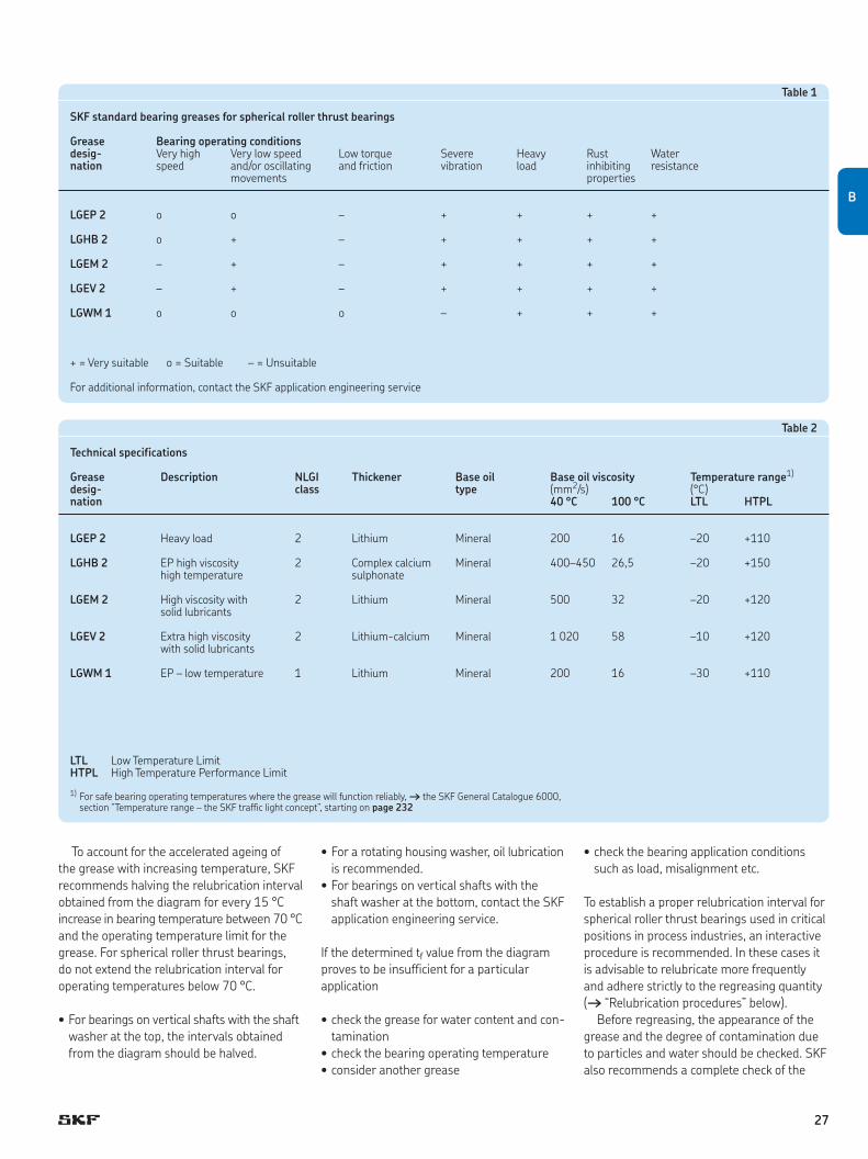
Table 1
SKF standard bearing greases for spherical roller thrust bearings
Grease Bearing operating conditionsdesig- Veryhigh Verylowspeed Lowtorque Severe Heavy Rust Waternation speed and/or oscillating and friction vibration load inhibiting resistance movements properties
LGEP 2 o o – + + + +
LGHB2 o + – + + + +
LGEM 2 – + – + + + +
LGEV 2 – + – + + + +
LGWM 1 o o o – + + +
+ = Very suitable o = Suitable – = Unsuitable
For additional information, contact the SKF application engineering service
Table 2
Technical specifications
Grease Description NLGI Thickener Base oil Base oil viscosity Temperature range1)
desig- class type (mm2/s) (°C)nation 40°C 100°C LTL HTPL
LGEP 2 Heavy load 2 Lithium Mineral 200 16 –20 +110
LGHB2 EP high viscosity 2 Complex calcium Mineral 400–450 26,5 –20 +150 high temperature sulphonate
LGEM 2 High viscosity with 2 Lithium Mineral 500 32 –20 +120 solid lubricants
LGEV 2 Extra high viscosity 2 Lithium-calcium Mineral 1 020 58 –10 +120 with solid lubricants
LGWM 1 EP – low temperature 1 Lithium Mineral 200 16 –30 +110
LTL Low Temperature LimitHTPL High Temperature Performance Limit
1) For safe bearing operating temperatures where the grease will function reliably, † the SKF General Catalogue 6000, section“Temperaturerange–theSKFtrafficlightconcept”,startingonpage 232
To account for the accelerated ageing of the grease with increasing temperature, SKF recommends halving the relubrication interval obtained from the diagram for every 15 °C increase in bearing temperature between 70 °C and the operating temperature limit for the grease. For spherical roller thrust bearings, do not extend the relubrication interval for operating temperatures below 70 °C.
•Forbearingsonverticalshaftswiththeshaftwasher at the top, the intervals obtained from the diagram should be halved.
•For a rotating housing washer, oil lubrication is recommended.
•Forbearingsonverticalshaftswiththeshaft washer at the bottom, contact the SKF application engineering service.
If the determined tf value from the diagram proves to be insufficient for a particular application
•checkthegreaseforwatercontentandcon-tamination
•checkthebearingoperatingtemperature•consideranothergrease
•checkthebearingapplicationconditionssuch as load, misalignment etc.
To establish a proper relubrication interval for spherical roller thrust bearings used in critical positions in process industries, an interactive procedure is recommended. In these cases it is advisable to relubricate more frequently and adhere strictly to the regreasing quantity (†“Relubricationprocedures”below).
Before regreasing, the appearance of the grease and the degree of contamination due to particles and water should be checked. SKF also recom mends a complete check of the
B
27

seals for wear, damage, and leakage. When the condition of the grease and associated components are satisfactory, the relubrication interval can be gradually increased.
Relubrication proceduresThe most common relubrication procedures for spherical roller thrust bearings are replen-ishment and continuous lubrication. The choice depends on the operat ing conditions.
•Replenishmentisaconvenientandpre-ferred procedure in many applications: it enables uninterrupted operation and pro-vides, when compared to continuous relu-brication, a lower steady state temperature.
•Continuousrelubricationisusedwhenthecalculated relubrication intervals are short or due to the adverse effects of con ta min-ation.
When using different bearing types on the same shaft, it is common practice to apply the lowest individual calcu lated relubrication interval for all bear ings. The guidelines and grease quantities for the relubrication pro ced-ures are provided below.
ReplenishmentSuitable quantities for replenishment can be obtained from
Gp = 0,005 D H
whereGp = grease quantity to be added when
replenishing, gD = bearing outside diameter, mmH = bearing height, mm
To facilitate the supply of grease using a grease gun, a grease nipple must be provided on the housing († figs. 5 and 6, page 26).
To be effective in replacing old grease, it is important to replenish while the machine is in operation. In cases where the machine is not in operation, the bearing should be ro tated during replenishment.
Where centralized lubrication equipment is used, provision must be made to adequately pump the grease at the lowest expected ambient temperature.
SKF recommends replacing complete grease fill after approximately 5 replenish-ments.
Continuous relubricationDue to possible churning of the grease that can lead to increased temperatures, continu-ous relubrication is only recommended when operating speeds are low, n dm values below 75 000. The quantity for relubrication per time unit is derived from the equation for Gp (see above) by spreading this quantity over the relubrication interval.
Maintenance
Proper bearing maintenance is a key factor to keep equipment running on schedule. Foresighted planning, use of professional main tenance techniques and tools combined with the appropriate bearing accessories are vital.
Further information about spherical roller thrust bearing maintenance can be found in the SKF Bearing Mainten ance Handbook or online at www.aptitudexchange.com.
What to look for during operationChecking the machine condition during oper-ation and planning for maintenance is import-ant. Bearings are vital components in most machines and monitoring their condition rep-resents an increasingly important activity in the field of pre ventive maintenance. A variety of systems and equipment are available to moni tor bear ings.
However, for practical reasons, not all machine functions are monitored using advanced instru mentation. By remaining alert for“troublesigns”,suchasnoise,increasesintemperature and vibration etc., problems can be detected.
ListenBearings in good operating condition produce a soft purring noise. Grinding, squeaking and other irregular sounds usually point to bear-ings in poor condition.
Damaged bearings produce irregular and loud noises. Instruments such as the SKF electronicstethoscopemake“listening”moreaccurate and help to detect damage at an earlier stage.
Feel the temperatureContinually check the temperature around the bearing. Any change in temperature can be an indication of a malfunction if the running con-ditions have not been altered. Temperature checks can be performed with an SKF therm-ometer.
After relubrication, a natural temper a ture rise lasting one or two days can occur.
LookCheck the condition of the seals near the bearing to be sure that they are operating satisfactorily and have not allowed contamin-ants to penetrate. Oil leaks are usually signs of worn seals, seal defects or loose plugs. Check the bearing arrangement and replace worn seals immediately.
Discoloration or darkening are usually signs that the lubricant contains impurities.
RelubricationRelubricationisbestperformedwhenthebearingisrunning.Relubricatewithsmallquantities each time.
Periodically, clean out used grease or purge out through drain plugs. When lubricating, always keep con taminants away from the grease.
Checking the oilCheck the oil level and when neces sary fill up or replace with the same type of oil. Take a sample of the used oil and compare it with fresh oil. If the sample looks cloudy, it may be mixed with water and should be replaced.
Dark oil is a sign of dirt, or indicates that the oil has started to carbonize. Clean the bearing and change the oil with a similar type of oil.
Condition monitoring of bearings in operationIt is advisable to systematically check the bearing condition. A lack of lubricant, exces-sive loads, high operating temperatures and mounting errors can all contribute to prema-ture bearing failure. By methodical condition monitoring, bearing damage can be detect ed at an early stage († fig. 7). It is then easy to plan for bearing replacement.
SKF can help you select the right monitor-ing system, train your personnel and install the system († pages 32 and 33).
28

Prepared for vibration analysisBearing damage can be identified by its defect frequency. To simplify vibration analysis, the packaging of SKF spherical roller thrust bear-ings is marked with individual bearing data required for damage analysis († fig. 8).
SKF offers a range of different instruments for condition monitoring. An example is the range of portable MARLIN machine inspection systems for fast and reliable vibration analysis
The packaging of SKF spherical roller thrust bearings is marked with vibration analysis data
Fig. 8
Fig. 7
B
29
Mounting and dismounting
MountingMounting bearings with an interference fitSKF spherical roller thrust bearings are separ able so that the housing washer and the shaft washer with rollers and cage are mounted independently († fig. 1).
One or both of the washers can have an interference fit.
Depending on whether the interfer ence fit is between a shaft washer and shaft or housing washer and housing, the shaft wash-er or the housing should be heated before mounting.
To mount a washer with an interfer ence fit on a shaft, heat the washer to about 80 to 90 °C (175 to 195 °F) above the temperature of the shaft. This can be done by means of an SKF induction heater († fig. 2), a heating cabinet or an oil bath.
Double direction thrust bearing arrangements – paired spherical roller thrust bearingsSpherical roller thrust bearings mount ed in pairs must be adjusted to a certain axial clear-ance, or preloaded during assembly († section “Axialclearanceandpreload”,starting on page 16).
In some cases, the correct position of the bearings must be determined from measure-ments of the bearing heights and the adjacent components before mounting.
New, unique detailed mounting and dis-mounting instructions for SKF spherical roller thrust bearings are available online at www.skf.com/mount.
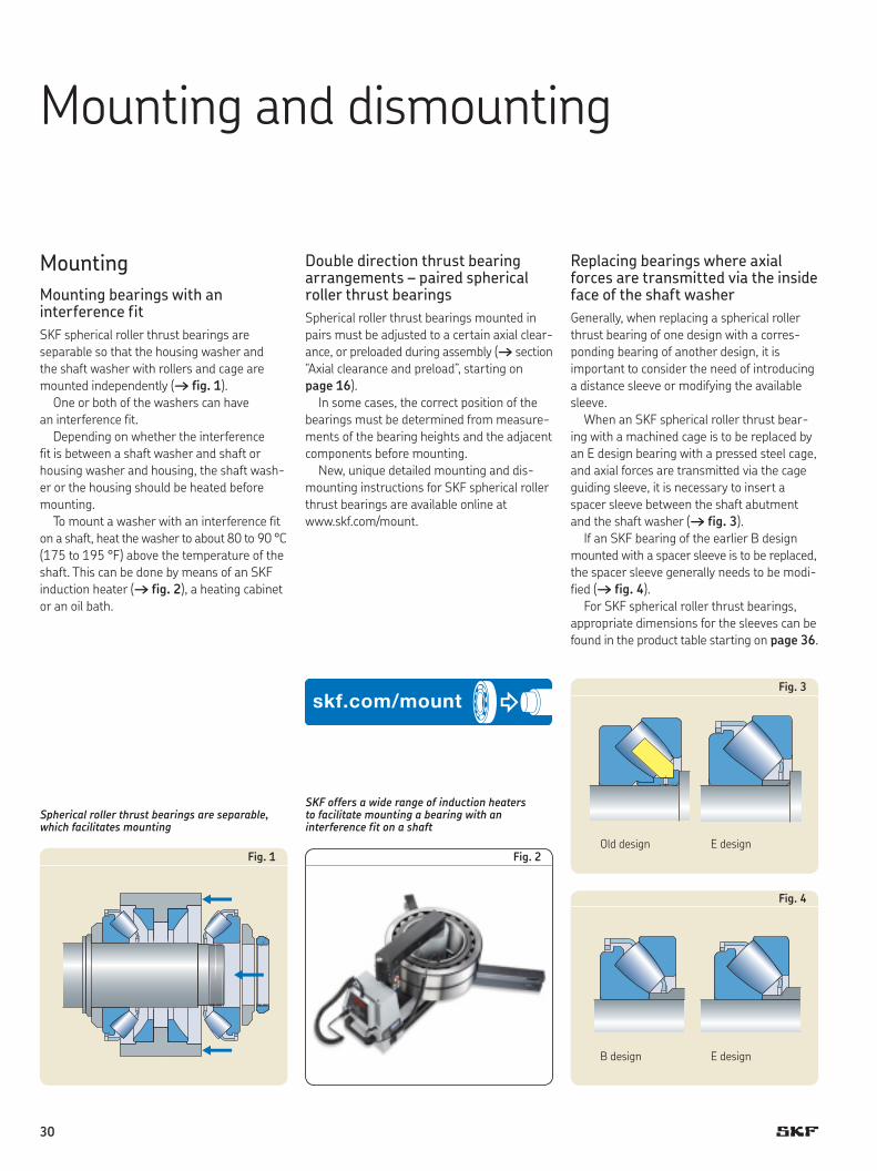
Replacing bearings where axial forces are transmitted via the inside face of the shaft washerGenerally, when replacing a spherical roller thrust bearing of one design with a corres-ponding bearing of another design, it is important to consider the need of introducing a distance sleeve or modifying the available sleeve.
When an SKF spherical roller thrust bear-ing with a machined cage is to be re placed by an E design bearing with a pressed steel cage, and axial forces are transmitted via the cage guiding sleeve, it is necessary to insert a spacer sleeve between the shaft abutment and the shaft washer († fig. 3).
If an SKF bearing of the earlier B design mounted with a spacer sleeve is to be replaced, the spacer sleeve generally needs to be modi-fied († fig. 4).
For SKF spherical roller thrust bearings, appropriate dimensions for the sleeves can be found in the product table starting on page 36.
Spherical roller thrust bearings are separable, which facilitates mounting
SKF offers a wide range of induction heaters to facilitate mounting a bearing with an interference fit on a shaft
Fig. 1 Fig. 2
Fig. 4
Fig. 3
Old design
B design
E design
E design
30
Dismounting
Removing the shaft washerA considerable amount of force is required to remove a washer mounted with an inter-ference fit. Washers of small and medium size bearings can usually be removed using a mechanical or hydraulic withdrawal tool.
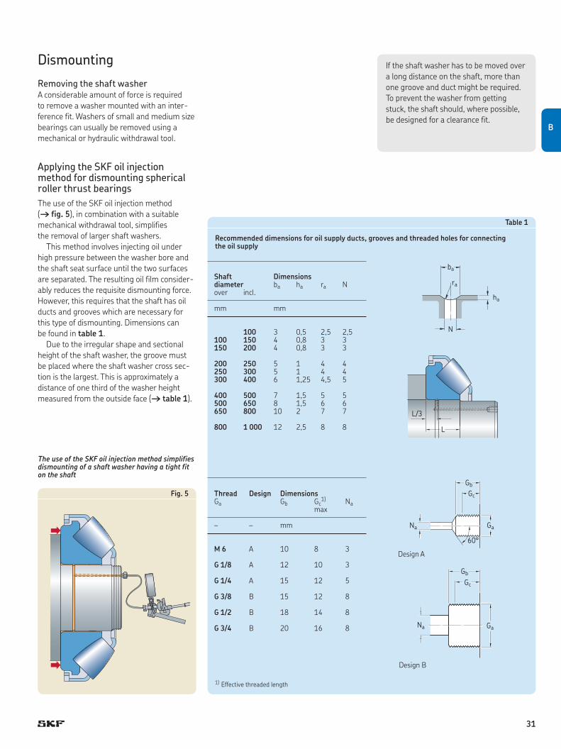
Applying the SKF oil injection method for dismounting spherical roller thrust bear ingsThe use of the SKF oil injection method († fig. 5), in combination with a suit able mechanical withdrawal tool, simplifies the removal of larger shaft washers.
This method involves injecting oil under high pressure between the washer bore and the shaft seat surface until the two surfaces are separated. The resulting oil film consider-ably reduces the requisite dismounting force. However, this requires that the shaft has oil ducts and grooves which are necessary for this type of dismounting. Dimensions can be found in table 1.
Due to the irregular shape and sectional height of the shaft washer, the groove must be placed where the shaft washer cross sec-tion is the largest. This is approximately a distance of one third of the washer height measured from the outside face († table 1).
The use of the SKF oil injection method simplifies dismounting of a shaft washer having a tight fit on the shaft
Table 1
Recommended dimensions for oil supply ducts, grooves and threaded holes for connecting the oil supply
1) Effective threaded length
Shaft Dimensionsdiameter ba ha ra Nover incl.
mm mm
100 3 0,5 2,5 2,5100 150 4 0,8 3 3150 200 4 0,8 3 3
200 250 5 1 4 4250 300 5 1 4 4300 400 6 1,25 4,5 5
400 500 7 1,5 5 5500 650 8 1,5 6 6650 800 10 2 7 7
800 1 000 12 2,5 8 8
Thread Design DimensionsGa Gb Gc
1) Na max
– – mm
M 6 A 10 8 3
G 1/8 A 12 10 3
G 1/4 A 15 12 5
G 3/8 B 15 12 8
G 1/2 B 18 14 8
G 3/4 B 20 16 8
60°
Na Ga
Gc
Gb
Na Ga
Gc
Gb
Design B
Design A
N
ha
ra
ba
L
L/3
If the shaft washer has to be moved over a long distance on the shaft, more than one groove and duct might be required. To prevent the washer from getting stuck, the shaft should, where possible, be designed for a clearance fit.
Fig. 5
B
31
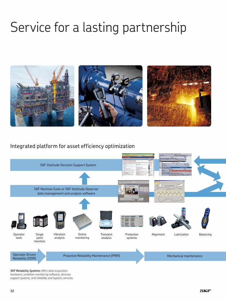
Integrated platform for asset efficiency optimization
SKF @ptitude Decision Support System
SKF Machine Suite or SKF @ptitude Observer data management and analysis software
Operator Driven Reliability (ODR)
Proactive Reliability Maintenance (PRM) Mechanical maintenance
Operator tools
Single point
monitors
Vibration analysis
Online monitoring
Protection systems
Transient analysis
Alignment Lubrication Balancing
SKF Reliability Systems offers data acquisition hard ware, condition monitoring software, decision support systems, and reliability and logistics services.
Service for a lasting partnership
32

Technology upgrades
Technology bearing
Maintenance tools
ERP/CMMS1)
Process control
Consulting services
Reliability services
Maintenance services
System installation
and management
services
Based on more than 100 years of experience with rotating equipment, SKF’s expertise begins at the component level and extends to a deep under standing of the technologies required to improve manufacturing processes.
Using this knowledge, SKF can work with you to design more efficiency into your machines and then provide maintenance solutions to keep those machines in peak operating condition.
SKF concepts for creating customer valueWith experience in virtually every industrial sector, SKF can provide solutions that go beyond simple maintenance to improve machine per-formance and productivity. With our Total Shaft Solutions concept, customers can take full advantage of our in-depth competence including, but not limited to
• rootcausefailureanalysis• maintenanceassessments• predictiveandpreventivemaintenance• lubricationandfiltrationmanagement• equipmentmaintenanceandmonitoring
– fans, pumps, gearboxes and spindles• precisionbalancing• precisionalignment• applications-specifictraining• componentandtechnologyupgrades• installationandrepairservices.
Another SKF concept that embraces a broader view of improving machine reliability is called Asset Efficiency Optimization (AEO). As the name implies, AEO recognizes the importance of treating machinery and equipment as plant assets. SKF programmes that take a systems approach to managing these assets include
• OperatorDrivenReliability(ODR)• ProactiveReliabilityMaintenance(PRM)• IntegratedMaintenanceSolutions,which
include all-inclusive contractual programmes.
For more information about SKF competen-cies and services contact your local SKF representative.
SKF uses its own product, service and knowledge capabilities, in combination with other providers, to implement a complete reliability programme based on specific business goals.
1)EnterpriseResourcePlanning/Computerized Maintenance Management System.
B
33
Bearing data – general
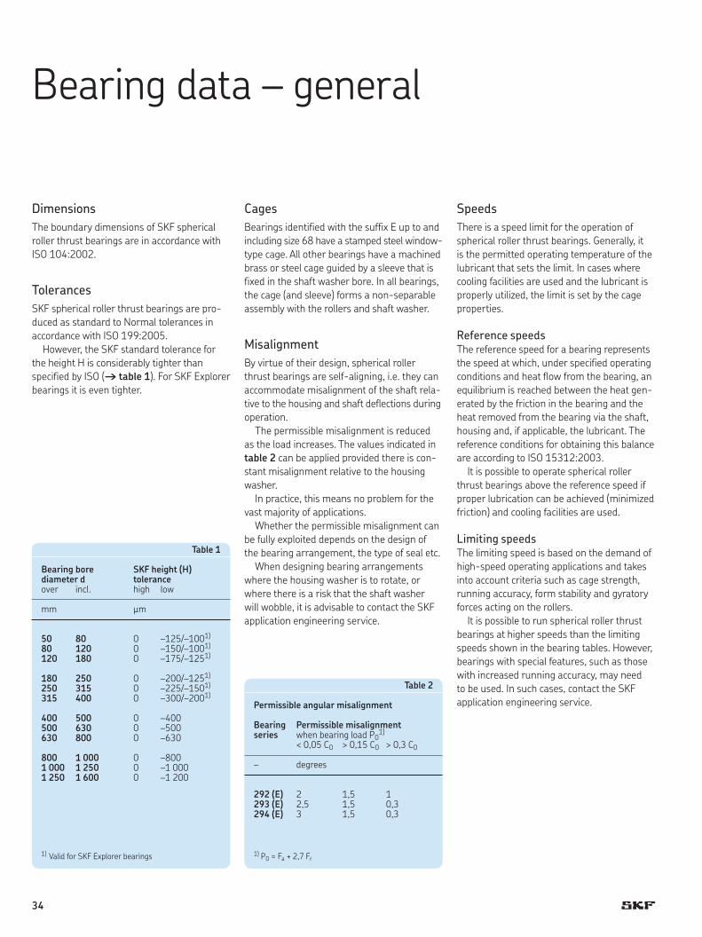
DimensionsThe boundary dimensions of SKF spherical roller thrust bearings are in accordance with ISO 104:2002.
TolerancesSKF spherical roller thrust bearings are pro-duced as standard to Normal tolerances in accordance with ISO 199:2005.
However, the SKF standard toler ance for the height H is considerably tighter than speci fied by ISO († table 1). For SKF Explorer bearings it is even tighter.
CagesBearings identified with the suffix E up to and including size 68 have a stamped steel window- type cage. All other bearings have a machined brass or steel cage guided by a sleeve that is fixed in the shaft washer bore. In all bearings, the cage (and sleeve) forms a non-separ able assembly with the rollers and shaft washer.
MisalignmentBy virtue of their design, spherical roller thrust bearings are self-aligning, i.e. they can accommodate misalignment of the shaft rela-tive to the housing and shaft deflections during operation.
The permissible misalignment is reduced as the load increases. The values indicated in table 2 can be applied provided there is con-stant misalignment relative to the housing washer.
In practice, this means no problem for the vast majority of applications.
Whether the permissible misalignment can be fully exploited depends on the design of the bearing arrangement, the type of seal etc.
When designing bearing arrangements where the housing washer is to rotate, or where there is a risk that the shaft washer will wobble, it is advis able to contact the SKF application engineering service.
SpeedsThere is a speed limit for the operation of spherical roller thrust bearings. Generally, it is the permitted operating temperature of the lubricant that sets the limit. In cases where cooling facili ties are used and the lubricant is properly utilized, the limit is set by the cage properties.
Reference speedsThe reference speed for a bearing represents the speed at which, under specified operating conditions and heat flow from the bearing, an equi librium is reached between the heat gen-erated by the friction in the bear ing and the heat removed from the bearing via the shaft, housing and, if applicable, the lubricant. The refer ence conditions for obtaining this balance are according to ISO 15312:2003.
It is possible to operate spherical roller thrust bearings above the refer ence speed if proper lubrication can be achieved (minimized friction) and cool ing facilities are used.
Limiting speedsThe limiting speed is based on the demand of high-speed operating applications and takes into account criteria such as cage strength, running accuracy, form stability and gyratory forces acting on the rollers.
It is possible to run spherical roller thrust bearings at higher speeds than the limiting speeds shown in the bear ing tables. However, bearings with special features, such as those with increased running accuracy, may need to be used. In such cases, contact the SKF application engineering service.
Table 1
Bearingbore SKFheight(H)diameter d toleranceover incl. high low
mm µm
50 80 0 –125/–1001)
80 120 0 –150/–1001)
120 180 0 –175/–1251)
180 250 0 –200/–1251)
250 315 0 –225/–1501)
315 400 0 –300/–2001)
400 500 0 –400500 630 0 –500630 800 0 –630
800 1 000 0 –8001 000 1 250 0 –1 0001 250 1 600 0 –1 200
1) Valid for SKF Explorer bearings
Table 2
Permissible angular misalignment
Bearing Permissible misalignmentseries when bearing load P0
1)
< 0,05 C0 > 0,15 C0 > 0,3 C0
– degrees
292(E) 2 1,5 1293(E) 2,5 1,5 0,3294(E) 3 1,5 0,3
1) P0 = Fa + 2,7 Fr
34
Influence of operating temperature on the bearing materialsAll SKF spherical roller thrust bearings are subjected to a special heat treatment so they can be used at tempera t ures up to +200 °C (390 °F).
Minimum loadIn order to provide satisfactory oper ation, spherical roller thrust bearings, like all ball and roller bear ings, must always be subjected to a given min imum load, particularly if they are to operate at high speeds or are subject ed to high accelerations or rapid changes in the direction of load. Under such conditions, the inertia forces of the rollers and cage, and the friction in the lubricant, can have a detrimental influence on the rolling conditions in the bear-ing and may cause damaging sliding move-ments to occur between the rollers and raceways.
The requisite minimum axial load to be applied to spherical roller thrust bearings can be estimated using
q n w2Fam = 1,8 Fr + A ——— < 1 000 z
whereFam = minimum axial load, kNFr = radial component of load for bearings
subjected to combined load, kNC0 = basic static load rating, kNA = minimum load factor († product table)n = rotational speed, r/min
If 1,8 Fr < 0,0005 C0 then 0,0005 C0 should be used in the above equation instead of 1,8 Fr.
At speeds higher than the reference speed or when starting up at low temperatures, or when the lubricant is highly viscous, even greater minimum loads may be required. The weight of the components supported by the bear ing, together with external forces, generally exceed the requisite min imum load. If this is not the case, the spherical roller thrust bearing must be preloaded, e.g. by use of springs.
However, when a spherical roller thrust bearing is radially guided and mounted with clearance, the axial minimum load can be reduced under certain conditions. Contact the SKF application engineering service for advice.
Supplementary designationsThe designation suffixes often used to identify certain features of SKF spher ical roller thrust bearings are explain ed in the following.
E Optimized internal design, window-type steel cage
EF Optimized internal design, machined steel cage
EM Optimized internal design, machined brass cage
N1 One locating slot in the housing washer
N2 Two locating slots slots, 180° apart, in the housing washer
VE447 Shaft washer with three equally spaced threaded holes in one side face to take hoisting tackle
VE447E As VE447, but with three appropriate eye bolts
VE632 Housing washer with three equally spaced threaded holes in one side face to take hoisting tackle
VU029 Internal design feature for bearings operating under combined loads without any spring loading and adjusted to a specific axial clearance
35
C
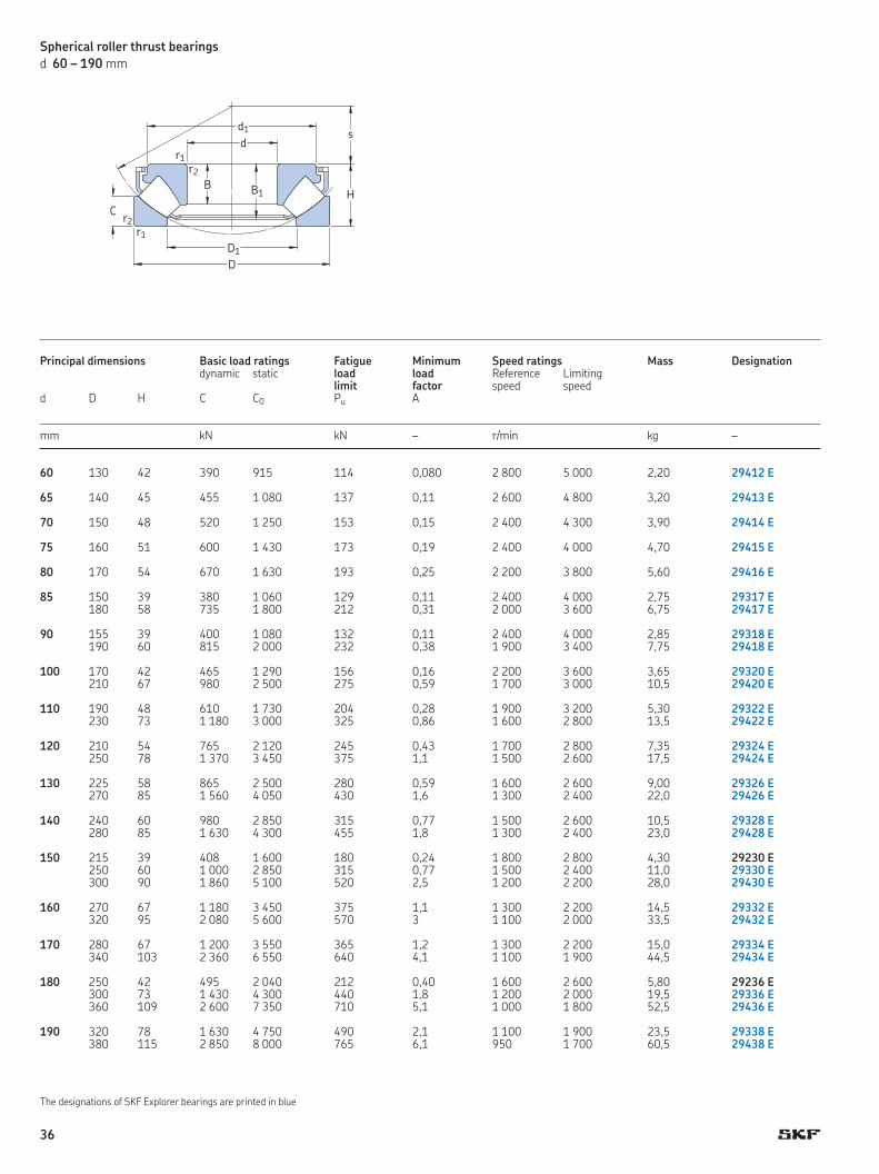
Spherical roller thrust bearingsd 60 – 190 mm
dd1
H
s
D1
D
C
r1
r2
r2B B1
r1
Principal dimensions Basic load ratings Fatigue Minimum Speed ratings Mass Designation dynamic static load load Reference Limiting limit factor speed speed d D H C C0 Pu A
mm kN kN – r/min kg –
60 130 42 390 915 114 0,080 2 800 5 000 2,20 29412 E 65 140 45 455 1 080 137 0,11 2 600 4 800 3,20 29413 E 70 150 48 520 1 250 153 0,15 2 400 4 300 3,90 29414 E 75 160 51 600 1 430 173 0,19 2 400 4 000 4,70 29415 E 80 170 54 670 1 630 193 0,25 2 200 3 800 5,60 29416 E 85 150 39 380 1 060 129 0,11 2 400 4 000 2,75 29317 E 180 58 735 1 800 212 0,31 2 000 3 600 6,75 29417 E 90 155 39 400 1 080 132 0,11 2 400 4 000 2,85 29318 E 190 60 815 2 000 232 0,38 1 900 3 400 7,75 29418 E 100 170 42 465 1 290 156 0,16 2 200 3 600 3,65 29320 E 210 67 980 2 500 275 0,59 1 700 3 000 10,5 29420 E 110 190 48 610 1 730 204 0,28 1 900 3 200 5,30 29322 E 230 73 1 180 3 000 325 0,86 1 600 2 800 13,5 29422 E 120 210 54 765 2 120 245 0,43 1 700 2 800 7,35 29324 E 250 78 1 370 3 450 375 1,1 1 500 2 600 17,5 29424 E 130 225 58 865 2 500 280 0,59 1 600 2 600 9,00 29326 E 270 85 1 560 4 050 430 1,6 1 300 2 400 22,0 29426 E 140 240 60 980 2 850 315 0,77 1 500 2 600 10,5 29328 E 280 85 1 630 4 300 455 1,8 1 300 2 400 23,0 29428 E 150 215 39 408 1 600 180 0,24 1 800 2 800 4,30 29230 E 250 60 1 000 2 850 315 0,77 1 500 2 400 11,0 29330 E 300 90 1 860 5 100 520 2,5 1 200 2 200 28,0 29430 E 160 270 67 1 180 3 450 375 1,1 1 300 2 200 14,5 29332 E 320 95 2 080 5 600 570 3 1 100 2 000 33,5 29432 E 170 280 67 1 200 3 550 365 1,2 1 300 2 200 15,0 29334 E 340 103 2 360 6 550 640 4,1 1 100 1 900 44,5 29434 E 180 250 42 495 2 040 212 0,40 1 600 2 600 5,80 29236 E 300 73 1 430 4 300 440 1,8 1 200 2 000 19,5 29336 E 360 109 2 600 7 350 710 5,1 1 000 1 800 52,5 29436 E 190 320 78 1 630 4 750 490 2,1 1 100 1 900 23,5 29338 E 380 115 2 850 8 000 765 6,1 950 1 700 60,5 29438 E
The designations of SKF Explorer bearings are printed in blue
36
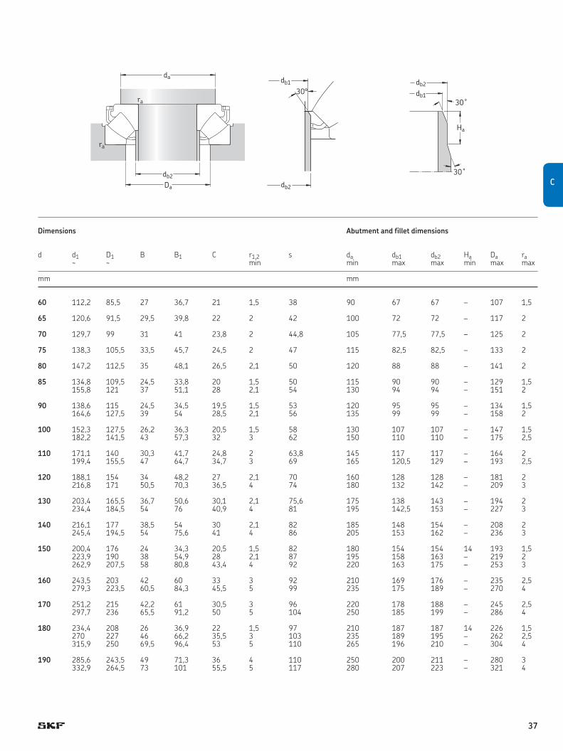
da
db2
Da
ra
ra
db2
30°db1 db2
30˚
30˚
db1
Ha
Dimensions Abutment and fillet dimensions
d d1 D1 B B1 C r1,2 s da db1 db2 Ha Da ra ~ ~ min min max max min max max
mm mm
60 112,2 85,5 27 36,7 21 1,5 38 90 67 67 – 107 1,5 65 120,6 91,5 29,5 39,8 22 2 42 100 72 72 – 117 2 70 129,7 99 31 41 23,8 2 44,8 105 77,5 77,5 – 125 2 75 138,3 105,5 33,5 45,7 24,5 2 47 115 82,5 82,5 – 133 2 80 147,2 112,5 35 48,1 26,5 2,1 50 120 88 88 – 141 2 85 134,8 109,5 24,5 33,8 20 1,5 50 115 90 90 – 129 1,5 155,8 121 37 51,1 28 2,1 54 130 94 94 – 151 2 90 138,6 115 24,5 34,5 19,5 1,5 53 120 95 95 – 134 1,5 164,6 127,5 39 54 28,5 2,1 56 135 99 99 – 158 2 100 152,3 127,5 26,2 36,3 20,5 1,5 58 130 107 107 – 147 1,5 182,2 141,5 43 57,3 32 3 62 150 110 110 – 175 2,5 110 171,1 140 30,3 41,7 24,8 2 63,8 145 117 117 – 164 2 199,4 155,5 47 64,7 34,7 3 69 165 120,5 129 – 193 2,5 120 188,1 154 34 48,2 27 2,1 70 160 128 128 – 181 2 216,8 171 50,5 70,3 36,5 4 74 180 132 142 – 209 3 130 203,4 165,5 36,7 50,6 30,1 2,1 75,6 175 138 143 – 194 2 234,4 184,5 54 76 40,9 4 81 195 142,5 153 – 227 3 140 216,1 177 38,5 54 30 2,1 82 185 148 154 – 208 2 245,4 194,5 54 75,6 41 4 86 205 153 162 – 236 3 150 200,4 176 24 34,3 20,5 1,5 82 180 154 154 14 193 1,5 223,9 190 38 54,9 28 2,1 87 195 158 163 – 219 2 262,9 207,5 58 80,8 43,4 4 92 220 163 175 – 253 3 160 243,5 203 42 60 33 3 92 210 169 176 – 235 2,5 279,3 223,5 60,5 84,3 45,5 5 99 235 175 189 – 270 4 170 251,2 215 42,2 61 30,5 3 96 220 178 188 – 245 2,5 297,7 236 65,5 91,2 50 5 104 250 185 199 – 286 4 180 234,4 208 26 36,9 22 1,5 97 210 187 187 14 226 1,5 270 227 46 66,2 35,5 3 103 235 189 195 – 262 2,5 315,9 250 69,5 96,4 53 5 110 265 196 210 – 304 4 190 285,6 243,5 49 71,3 36 4 110 250 200 211 – 280 3 332,9 264,5 73 101 55,5 5 117 280 207 223 – 321 4
C
37
C

Principal dimensions Basic load ratings Fatigue Minimum Speed ratings Mass Designation dynamic static load load Reference Limiting limit factor speed speedd D H C C0 Pu A
mm kN kN – r/min kg –
Spherical roller thrust bearingsd 200 – 420 mm
200 280 48 656 2 650 285 0,67 1 400 2 200 9,30 29240 E 340 85 1 860 5 500 550 2,9 1 000 1 700 29,5 29340 E 400 122 3 200 9 000 850 7,7 850 1 600 72,0 29440 E 220 300 48 690 3 000 310 0,86 1 300 2 200 10,0 29244 E 360 85 2 000 6 300 610 3,8 1 000 1 700 33,5 29344 E 420 122 3 350 9 650 900 8,8 850 1 500 75,0 29444 E 240 340 60 799 3 450 335 1,1 1 100 1 800 16,5 29248 380 85 2 040 6 550 630 4,1 1 000 1 600 35,5 29348 E 440 122 3 400 10 200 930 9,9 850 1 500 80,0 29448 E 260 360 60 817 3 650 345 1,3 1 100 1 700 18,5 29252 420 95 2 550 8 300 780 6,5 850 1 400 49,0 29352 E 480 132 4 050 12 900 1 080 16 750 1 300 105 29452 E 280 380 60 863 4 000 375 1,5 1 000 1 700 19,5 29256 440 95 2 550 8 650 800 7,1 850 1 400 53,0 29356 E 520 145 4 900 15 300 1 320 22 670 1 200 135 29456 E 300 420 73 1 070 4 800 465 2,2 900 1 400 30,5 29260 480 109 3 100 10 600 930 11 750 1 200 75,0 29360 E 540 145 4 310 16 600 1 340 26 600 1 200 140 29460 E 320 440 73 1 110 5 100 465 2,5 850 1 400 33,0 29264 500 109 3 350 11 200 1 000 12 750 1 200 78,0 29364 E 580 155 4 950 19 000 1 530 34 560 1 100 175 29464 E 340 460 73 1 130 5 400 480 2,8 850 1 300 33,5 29268 540 122 2 710 11 000 950 11 600 1 100 105 29368 620 170 5 750 22 400 1 760 48 500 1 000 220 29468 E 360 500 85 1 460 6 800 585 4,4 750 1 200 52,0 29272 560 122 2 760 11 600 980 13 600 1 100 110 29372 640 170 5 350 21 200 1 630 43 500 950 230 29472 EM
380 520 85 1 580 7 650 655 5,6 700 1 100 53,0 29276 600 132 3 340 14 000 1 160 19 530 1 000 140 29376 670 175 5 870 24 000 1 860 55 480 900 260 29476 EM 400 540 85 1 610 8 000 695 6,1 700 1 100 55,5 29280 620 132 3 450 14 600 1 200 20 530 950 150 29380 710 185 6 560 26 500 1 960 67 450 850 310 29480 EM 420 580 95 1 990 9 800 815 9,1 630 1 000 75,5 29284 650 140 3 740 16 000 1 290 24 500 900 170 29384 730 185 6 730 27 500 2 080 72 430 850 325 29484 EM
The designations of SKF Explorer bearings are printed in blue
B
B1
dd1
H
s
D1
D
C
r1
r2
r2B B1
r1
38
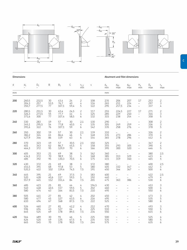
Dimensions Abutment and fillet dimensions
d d1 D1 B B1 C r1,2 s da db1 db2 Ha Da ra ~ ~ min min max max min max max
mm mm
200 260,5 232,5 30 43,4 24 2 108 235 206 207 17 253 2 304,3 257 53,5 76,7 40 4 116 265 211 224 – 297 3 350,7 277,5 77 107,1 59,4 5 122 295 217,5 234 – 337 4 220 280,5 251,5 30 43,4 24,5 2 117 255 224,5 227 17 271 2 326,3 273,5 55 77,7 41 4 125 285 229 240 – 316 3 371,6 300 77 107,4 58,5 6 132 315 238 254 – 358 5 240 330 283 19 57 30 2,1 130 290 – – – 308 2 345,1 295,5 54 77,8 40,5 4 135 305 249 259 – 336 3 391,6 322 76 107,1 59 6 142 335 258 276 – 378 5 260 350 302 19 57 30 2,1 139 310 – – – 326 2 382,2 324 61 86,6 46 5 148 335 273 286 – 370 4 427,9 346 86 119 63 6 154 365 278 296 – 412 5 280 370 323 19 57 30,5 2,1 150 325 – – – 347 2 401 343 62 86,7 45,5 5 158 355 293 305 – 390 4 464,3 372 95 129,9 70 6 166 395 300 320 – 446 5 300 405 353 21 69 38 3 162 360 – – – 380 2,5 434,1 372 70 98,9 51 5 168 385 313 329 – 423 4 485 392 95 130,3 70,5 6 175 415 319 340 – 465 5 320 430 372 21 69 38 3 172 380 – – – 400 2,5 454,5 391 68 97,8 53 5 180 405 332 347 – 442 4 520,3 422 102 139,4 74,5 7,5 191 450 344 367 – 500 6 340 445 395 21 69 37,5 3 183 400 – – – 422 2,5 520 428 40,6 117 59,5 5 192 440 – – – 479 4 557,9 445 112 151,4 84 7,5 201 475 363 386 – 530 6 360 485 423 25 81 44 4 194,5 430 – – – 453 3 540 448 40,5 117 59,5 5 202 460 – – – 500 4 580 474 63 164 83,5 7,5 210 495 – – – 550 6 380 505 441 27 81 42 4 202 450 – – – 473 3 580 477 45 127 63,5 6 216 495 – – – 535 5 610 494 67 168 87,5 7,5 222 525 – – – 580 6 400 526 460 27 81 42,2 4 212 470 – – – 493 3 596 494 43 127 64 6 225 510 – – – 550 5 645 525 69 178 89,5 7,5 234 550 – – – 615 6 420 564 489 30 91 46 5 225 500 – – – 525 4 626 520 49 135 67,5 6 235 535 – – – 580 5 665 545 70 178 90,5 7,5 244 575 – – – 635 6
db2
30°db1 db2
30˚
30˚
db1
Ha
da
db2
Da
ra
ra
CC
39
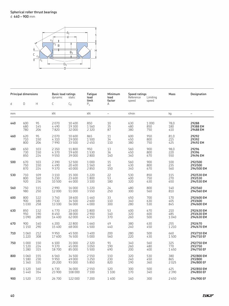
Spherical roller thrust bearingsd 440 – 900 mm
Principal dimensions Basic load ratings Fatigue Minimum Speed ratings Mass Designation dynamic static load load Reference Limiting limit factor speed speedd D H C C0 Pu A
mm kN kN – r/min kg –
440 600 95 2 070 10 400 850 10 630 1 000 78,0 29288 680 145 4 490 19 300 1 560 35 480 850 180 29388 EM 780 206 7 820 32 000 2 320 87 380 750 410 29488 EM 460 620 95 2 070 10 600 865 11 600 950 81,0 29292 710 150 4 310 19 000 1 500 34 450 800 215 29392 800 206 7 990 33 500 2 450 110 380 750 425 29492 EM 480 650 103 2 350 11 800 950 13 560 900 98,0 29296 730 150 4 370 19 600 1 530 36 450 800 220 29396 850 224 9 550 39 000 2 800 140 340 670 550 29496 EM 500 670 103 2 390 12 500 1 000 15 560 900 100 292/500 750 150 4 490 20 400 1 560 40 430 800 235 293/500 870 224 9 370 40 000 2 850 150 340 670 560 294/500 EM 530 710 109 3 110 15 300 1 220 22 530 850 115 292/530 EM 800 160 5 230 23 600 1 800 53 400 750 270 293/530 920 236 10 500 44 000 3 100 180 320 630 650 294/530 EM 560 750 115 2 990 16 000 1 220 24 480 800 140 292/560 980 250 12 000 51 000 3 550 250 300 560 810 294/560 EM 600 800 122 3 740 18 600 1 460 33 450 700 170 292/600 EM 900 180 7 530 34 500 2 600 110 340 630 405 293/600 1 030 258 13 100 56 000 4 000 300 280 530 845 294/600 EM 630 850 132 4 770 23 600 1 800 53 400 670 210 292/630 EM 950 190 8 450 38 000 2 900 140 320 600 485 293/630 EM 1 090 280 14 400 62 000 4 150 370 260 500 1 040 294/630 EM
670 900 140 4 200 22 800 1 660 49 380 630 255 292/670 1 150 290 15 400 68 000 4 500 440 240 450 1 210 294/670 EM 710 1 060 212 9 950 45 500 3 400 200 280 500 660 293/710 EM 1 220 308 17 600 76 500 5 000 560 220 430 1 500 294/710 EF 750 1 000 150 6 100 31 000 2 320 91 340 560 325 292/750 EM 1 120 224 9 370 45 000 3 050 190 260 480 770 293/750 1 280 315 18 700 85 000 5 500 690 200 400 1 650 294/750 EF 800 1 060 155 6 560 34 500 2 550 110 320 530 380 292/800 EM 1 180 230 9 950 49 000 3 250 230 240 450 865 293/800 1 360 335 20 200 93 000 5 850 820 190 360 2 025 294/800 EF 850 1 120 160 6 730 36 000 2 550 120 300 500 425 292/850 EM 1 440 354 23 900 108 000 7 100 1 100 170 340 2 390 294/850 EF 900 1 520 372 26 700 122 000 7 200 1 400 160 300 2 650 294/900 EF
dd1
H
s
D1
D
C
r1
r2
r2 B
B1
r1
40
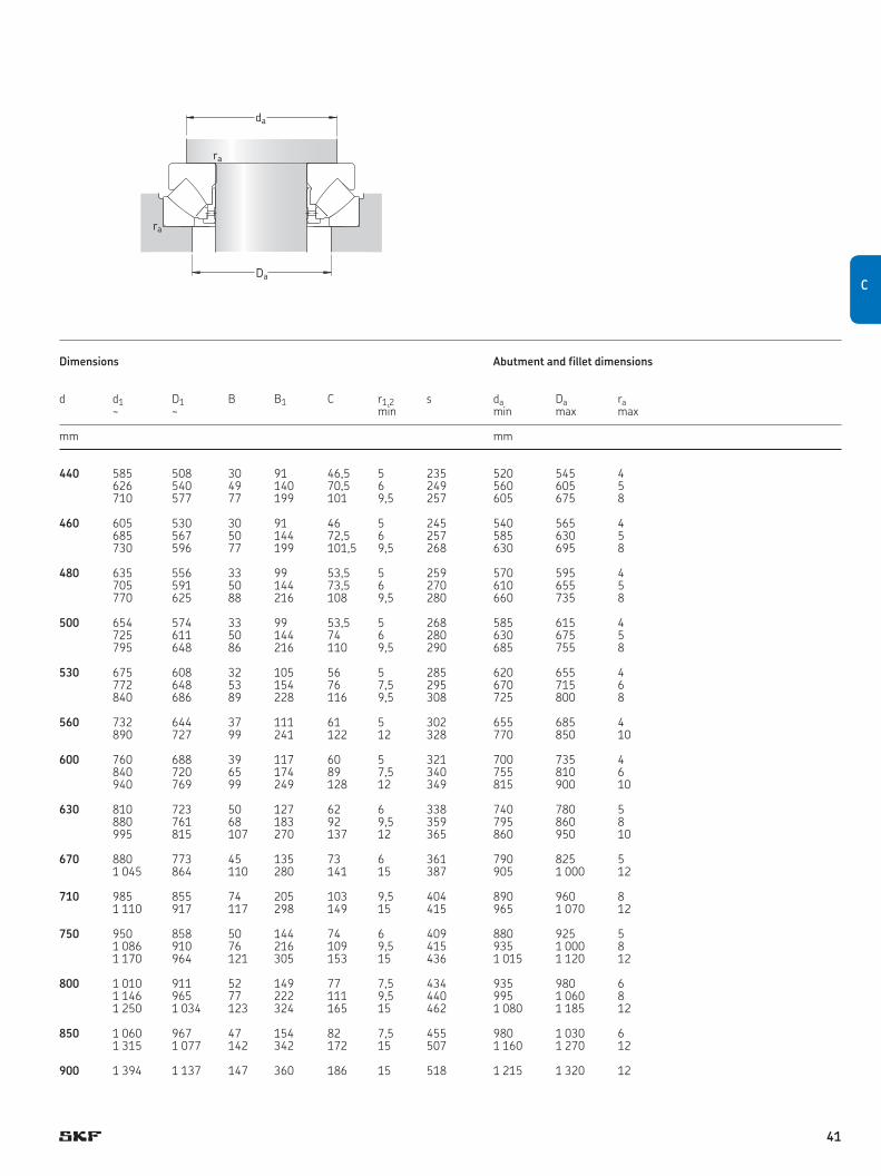
da
ra
ra
Da
Dimensions Abutment and fillet dimensions
d d1 D1 B B1 C r1,2 s da Da ra ~ ~ min min max max
mm mm
440 585 508 30 91 46,5 5 235 520 545 4 626 540 49 140 70,5 6 249 560 605 5 710 577 77 199 101 9,5 257 605 675 8 460 605 530 30 91 46 5 245 540 565 4 685 567 50 144 72,5 6 257 585 630 5 730 596 77 199 101,5 9,5 268 630 695 8 480 635 556 33 99 53,5 5 259 570 595 4 705 591 50 144 73,5 6 270 610 655 5 770 625 88 216 108 9,5 280 660 735 8 500 654 574 33 99 53,5 5 268 585 615 4 725 611 50 144 74 6 280 630 675 5 795 648 86 216 110 9,5 290 685 755 8 530 675 608 32 105 56 5 285 620 655 4 772 648 53 154 76 7,5 295 670 715 6 840 686 89 228 116 9,5 308 725 800 8 560 732 644 37 111 61 5 302 655 685 4 890 727 99 241 122 12 328 770 850 10 600 760 688 39 117 60 5 321 700 735 4 840 720 65 174 89 7,5 340 755 810 6 940 769 99 249 128 12 349 815 900 10
630 810 723 50 127 62 6 338 740 780 5 880 761 68 183 92 9,5 359 795 860 8 995 815 107 270 137 12 365 860 950 10
670 880 773 45 135 73 6 361 790 825 5 1 045 864 110 280 141 15 387 905 1 000 12
710 985 855 74 205 103 9,5 404 890 960 8 1 110 917 117 298 149 15 415 965 1 070 12
750 950 858 50 144 74 6 409 880 925 5 1 086 910 76 216 109 9,5 415 935 1 000 8 1 170 964 121 305 153 15 436 1 015 1 120 12
800 1 010 911 52 149 77 7,5 434 935 980 6 1 146 965 77 222 111 9,5 440 995 1 060 8 1 250 1 034 123 324 165 15 462 1 080 1 185 12
850 1 060 967 47 154 82 7,5 455 980 1 030 6 1 315 1 077 142 342 172 15 507 1 160 1 270 12
900 1 394 1 137 147 360 186 15 518 1 215 1 320 12
CC
41
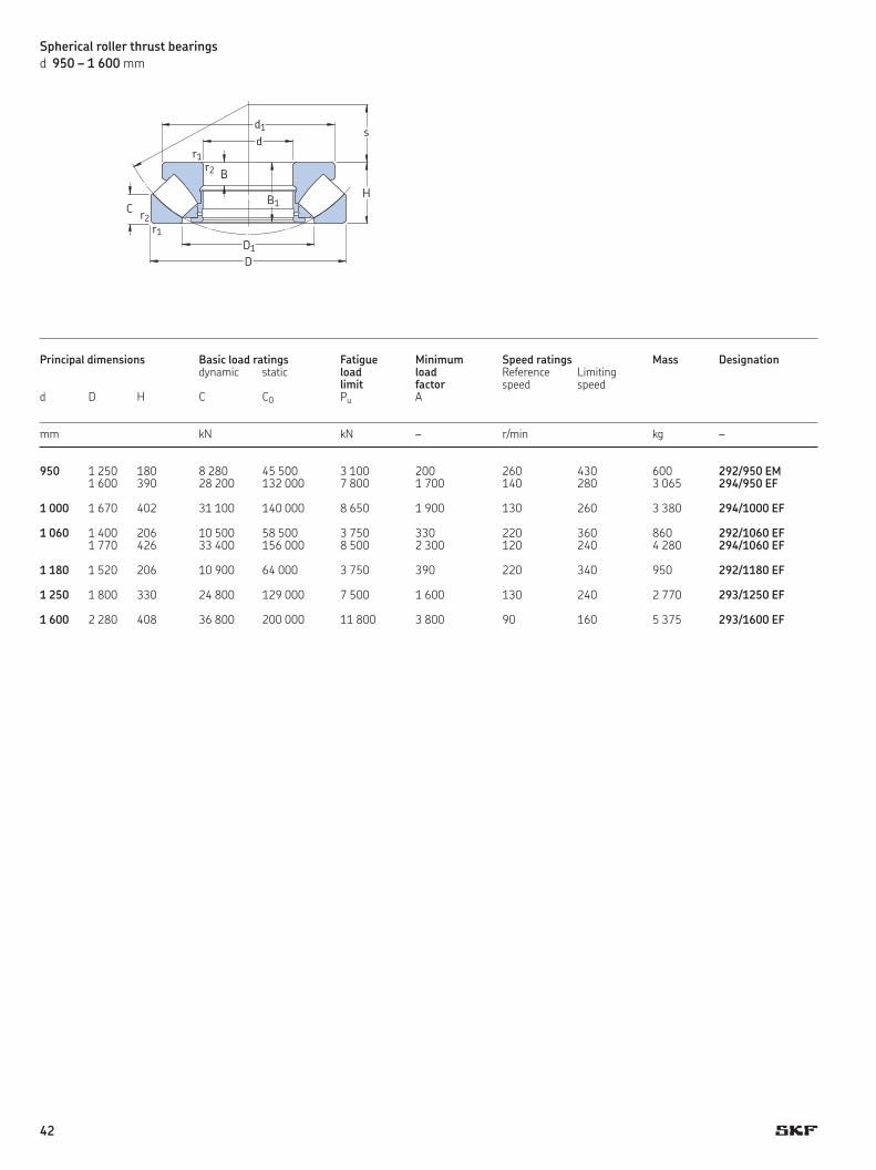
Spherical roller thrust bearingsd 950 – 1 600 mm
Principal dimensions Basic load ratings Fatigue Minimum Speed ratings Mass Designation dynamic static load load Reference Limiting limit factor speed speedd D H C C0 Pu A
mm kN kN – r/min kg –
950 1 250 180 8 280 45 500 3 100 200 260 430 600 292/950 EM 1 600 390 28 200 132 000 7 800 1 700 140 280 3 065 294/950 EF 1 000 1 670 402 31 100 140 000 8 650 1 900 130 260 3 380 294/1000 EF
1 060 1 400 206 10 500 58 500 3 750 330 220 360 860 292/1060 EF 1 770 426 33 400 156 000 8 500 2 300 120 240 4 280 294/1060 EF 1 180 1 520 206 10 900 64 000 3 750 390 220 340 950 292/1180 EF 1 250 1 800 330 24 800 129 000 7 500 1 600 130 240 2 770 293/1250 EF 1 600 2 280 408 36 800 200 000 11 800 3 800 90 160 5 375 293/1600 EF
dd1
H
s
D1
D
C
r1
r2
r2 B
B1
r1
42
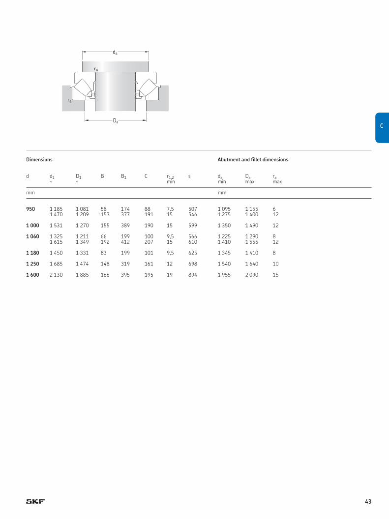
Dimensions Abutment and fillet dimensions
d d1 D1 B B1 C r1,2 s da Da ra ~ ~ min min max max
mm mm
950 1 185 1 081 58 174 88 7,5 507 1 095 1 155 6 1 470 1 209 153 377 191 15 546 1 275 1 400 12
1 000 1 531 1 270 155 389 190 15 599 1 350 1 490 12
1 060 1 325 1 211 66 199 100 9,5 566 1 225 1 290 8 1 615 1 349 192 412 207 15 610 1 410 1 555 12
1 180 1 450 1 331 83 199 101 9,5 625 1 345 1 410 8
1 250 1 685 1 474 148 319 161 12 698 1 540 1 640 10
1 600 2 130 1 885 166 395 195 19 894 1 955 2 090 15
da
ra
ra
DaCC
43
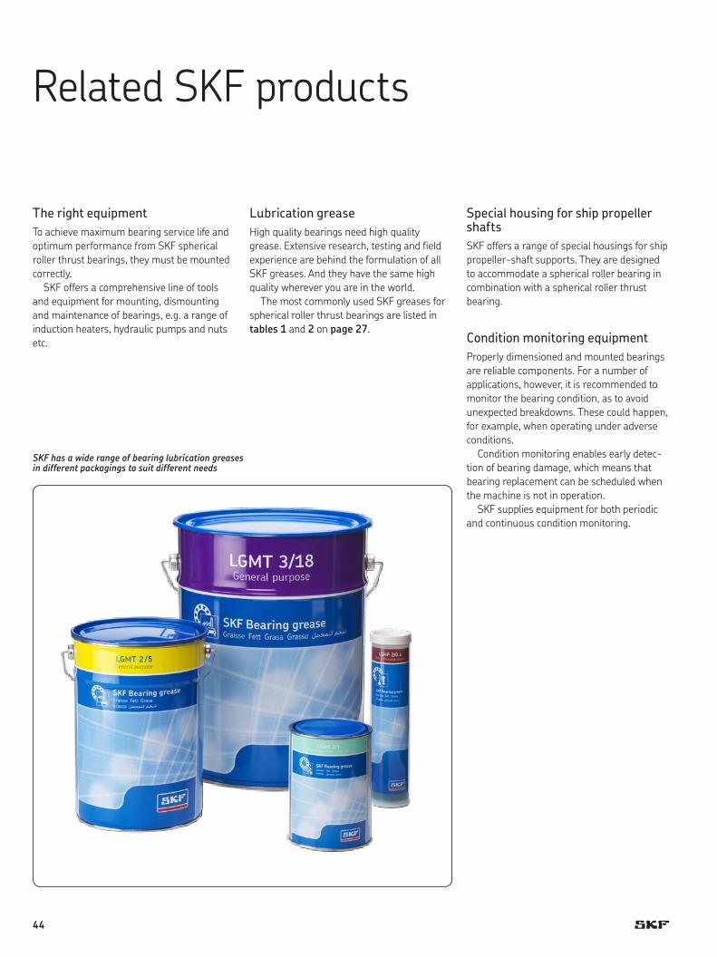
RelatedSKFproducts
The right equipmentTo achieve maximum bearing service life and optimum performance from SKF spherical roller thrust bearings, they must be mounted correctly.
SKF offers a comprehensive line of tools and equipment for mounting, dismounting and maintenance of bear ings, e.g. a range of induction heaters, hydraulic pumps and nuts etc.
Lubrication greaseHigh quality bearings need high qual ity grease. Extensive research, testing and field experience are behind the formulation of all SKF greases. And they have the same high quality wher ever you are in the world.
The most commonly used SKF greases for spherical roller thrust bearings are listed in tables 1 and 2 on page 27.
Special housing for ship propeller shaftsSKF offers a range of special housings for ship propeller-shaft supports. They are designed to accommodate a spher ical roller bearing in combination with a spherical roller thrust bearing.
Condition monitoring equipmentProperly dimensioned and mounted bearings are reliable components. For a number of applications, however, it is recommended to monitor the bear ing condition, as to avoid unexpected breakdowns. These could happen, for example, when operating under adverse conditions.
Condition monitoring enables early detec-tion of bearing damage, which means that bearing replacement can be scheduled when the machine is not in operation.
SKF supplies equipment for both periodic and continuous condition monitoring.
SKF has a wide range of bearing lubrication greases in different packagings to suit different needs
44
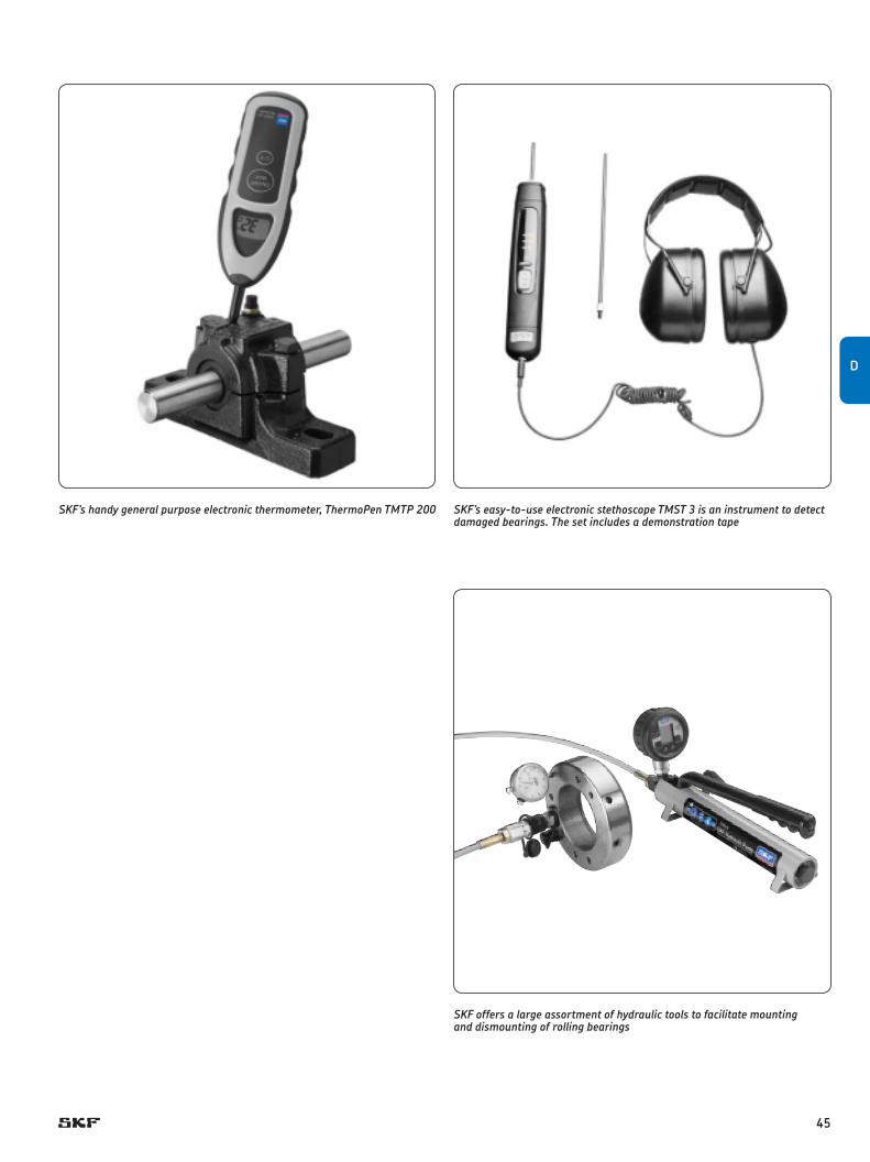
SKF’s handy general purpose electronic thermometer, ThermoPen TMTP 200 SKF’s easy-to-use electronic stethoscope TMST 3 is an instrument to detect damaged bearings. The set includes a demonstration tape
SKF offers a large assortment of hydraulic tools to facilitate mounting and dismounting of rolling bearings
D
45
Evolving by-wire technology SKF has a unique expertise in the fast-growing by-wire technology, from fly-by-wire, to drive-by-wire, to work-by-wire. SKF pioneered practical fly-by-wire technology and is a close working partner with all aerospace industry leaders. As an example, virtu-ally all aircraft of the Airbus design use SKF by-wire systems for cockpit flight control.
SKF – the knowledge engineering company
From the company that invented the self-align ing ball bearing more than 100 years ago, SKF has evol ved into a knowledge engin-eering company that is able to draw on five technology platforms to create unique solu-tions for its custom ers. These platforms include bearings, bearing units and seals, of course, but extend to other areas including: lubricants and lubrication sys tems, critical for long bearing life in many appli cations; mecha-tronics that combine mech anical and electron-ics knowledge into systems for more effective linear motion and sensorized solutions; and a full range of ser vices, from design and logis-tics support to con dition monitoring and reli-ability systems.
Though the scope has broadened, SKF continues to maintain the world’s leadership in the design, manufacture and marketing of rolling bearings, as well as complementary products such as radial seals. SKF also holds an increasingly important position in the mar-ket for linear motion products, high-precision aerospace bearings, machine tool spindles and plant maintenance services.
© Airbus – photo: exm company, H. Goussé
The SKF Group is globally certified to ISO 14001, the international standard for enviro n-mental management, as well as OHSAS 18001, the health and safety manage ment standard. Individual divisions have been ap proved for quality certification in ac cord ance with ISO 9001 and other customer specific requirements.
With over 100 manufacturing sites world-wide and sales companies in 70 countries, SKF is a truly international corporation. In addition, our distributors and dealers in some 15 000 locations around the world, an e-business marketplace and a global distri-bution system put SKF close to customers for the supply of both products and services. In essence, SKF solutions are available wherever and whenever customers need them. Over - all, the SKF brand and the corporation are stronger than ever. As the knowledge engin-eering company, we stand ready to serve you with world-class product competencies, intellectual resources, and the vision to help you succeed.
Bearings and unitsSeals Lubrication
systems
Mechatronics Services
SKF is also a leader in automotive by-wire technol-ogy, and has partnered with automotive engin eers to develop two concept cars, which employ SKF mecha -tronics for steering and braking. Further by-wire develop ment has led SKF to produce an all-electric forklift truck, which uses mecha tronics rather than hydraulics for all controls.
46

Developing a cleaner cleanerThe electric motor and its bearings are the heart of many household appliances. SKF works closely with appliance manufacturers to improve their products’ per-formance, cut costs, reduce weight, and reduce energy consumption. A recent example of this cooperation is a new generation of vacuum cleaners with sub-stantially more suction. SKF knowledge in the area of small bearing technology is also applied to manufacturers of power tools and office equipment.
Harnessing wind powerThe growing industry of wind-generated electric power provides a source of clean, green electricity. SKF is working closely with global industry leaders to develop efficient and trouble-free turbines, providing a wide range of large, highly specialized bearings and condition monitoring systems to extend equipment life of wind farms located in even the most remote and inhospitable environments.
Working in extreme environmentsIn frigid winters, especially in northern countries, extreme sub-zero tempera-tures can cause bearings in railway axleboxes to seize due to lubrication starva-tion. SKF created a new family of synthetic lubricants formulated to retain their lubrication viscosity even at these extreme temperatures. SKF knowledge enables manufacturers and end user customers to overcome the performance issues resulting from extreme temperatures, whether hot or cold. For example, SKF products are at work in diverse environments such as baking ovens and instant freezing in food processing plants.
Maintaining a 350 km/h R&D labIn addition to SKF’s renowned research and development facilities in Europe and the United States, Formula One car racing provides a unique environment for SKF to push the limits of bearing technology. For over 60 years, SKF products, engineering and knowledge have helped make Scuderia Ferrari a formidable force in F1 racing. (The average racing Ferrari utilizes around 150 SKF compo-nents.) Lessons learned here are applied to the products we provide to automak-ers and the aftermarket worldwide.
Delivering Asset Efficiency Optimization Through SKF Reliability Systems, SKF provides a comprehensive range of asset efficiency products and services, from condition monitoring hardware and soft-ware to maintenance strategies, engineering assistance and machine reliability programmes. To optimize efficiency and boost productivity, some industrial facil-ities opt for an Integrated Maintenance Solution, in which SKF delivers all ser-vices under one fixed-fee, performance-based contract.
Planning for sustainable growth By their very nature, bearings make a positive contribution to the natural envir-onment, enabling machinery to operate more efficiently, consume less power, and require less lubrication. By raising the performance bar for our own prod-ucts, SKF is enabling a new generation of high-efficiency products and equip-ment. With an eye to the future and the world we will leave to our children, the SKF Group policy on environment, health and safety, as well as the manufactur-ing techniques, are planned and implemented to help protect and preserve the earth’s limited natural resources. We remain committed to sustainable, environ-mentally responsible growth.
D
47

® SKF, @PTITUDE, WAVEandMARLINareregisteredtrademarks of the SKF Group.
™ SKFEXPLORERandTOTALSHAFTSOLUTIONaretrademarks of the SKF Group.
© SKF Group 2010The contents of this publication are the copyright of the publisher and may not be reproduced (even extracts) unless prior written permission is granted. Every care has been taken to ensure the accuracy of the information contained in this publication but no liability can be accepted for any loss or damage whether direct, indirect or consequential arising out of the use of the information contained herein.
PUB BU/P2 06104/1EN · June 2010
Printed in Sweden on environmentally friendly paper. skf.com