sj3 sj5 sj6 sj7 - tlv · sj5 60 50 (44) (37) 17 19 21/ 32 /3 4 sj6 90 120 (66) (88) 22 30 /7...
TRANSCRIPT

SJ SERIES FREE FLOAT TYPE STEAM TRAP
SJ3SJ5
SJ6SJ7
INSTRUCTION MANUALKeep this manual in a safe place for future reference
Copyright (C) 2018 by TLV CO., LTD. All rights reserved.
881 Nagasuna, Noguchi, Kakogawa, Hyogo 675-8511, Japan
Manufacturer
Tel: [81]-(0)79-422-1122 Fax: [81]-(0)79-422-0112

IntroductionBefore beginning installation or maintenance, please read this manual to ensure correct use of the product. Keep the manual in a safe place for future reference.
The inline repairable SJ Series steam traps with thermostatic bimetal air vent are suitable for a wide range of applications with small-to-large capacities and pressures up to 1.4 MPaG (200 psig); such as heat exchangers, tank heaters, dryers and process equipment. The traps discharge condensate continuously and automatically, at a temperature slightly lower than saturation temperature.
1 MPa = 10.197 kg/cm2, 1 bar = 0.1 MPa
For products with special specifications or with options not included in this manual, contact TLV for instructions.
The contents of this manual are subject to change without notice.

1. Safety Considerations• Read this section carefully before use and be sure to follow the instructions.• Installation, inspection, maintenance, repairs, disassembly, adjustment and valve
opening/closing should be carried out only by trained maintenance personnel.• The precautions listed in this manual are designed to ensure safety and prevent equipment
damage and personal injury. For situations that may occur as a result of erroneous handling, three different types of cautionary items are used to indicate the degree of urgency and the scale of potential damage and danger: DANGER, WARNING and CAUTION.
• The three types of cautionary items above are very important for safety; be sure to observe all of them, as they relate to installation, use, maintenance, and repair. Furthermore, TLV accepts no responsibility for any accidents or damage occurring as a result of failure to observe these precautions.
Indicates an urgent situation which poses a threat of death or serious injury.
Indicates that there is a potential threat of death or serious injury.
WARNING
CAUTION
WARNINGDANGER CAUTION
Indicates that there is a possibility of injury or equip-ment/product damage.
NEVER apply direct heat to the float. The float may explode due to increased internal pressure, causing accidents leading to serious injury or damage to property and equipment.
Install properly and DO NOT use this product outside the recommended operating pressure, temperature and other specification ranges. Improper use may result in such hazards as damage to the product or malfunctions, which may lead to serious accidents. Local regulations may restrict the use of this product to below the conditions quoted.
Take measures to prevent people from coming into direct contact with product outlets. Failure to do so may result in burns or other injury from the discharge of fluids.
DO NOT use this product in excess of the maximum operating pressure differential. Such use could make discharge impossible.
When disassembling or removing the product, wait until the internal pressure equals atmospheric pressure and the surface of the product has cooled to room temperature. Disassembling or removing the product when it is hot or under pressure may lead to discharge of fluids, causing burns, other injuries or damage.Be sure to use only the recommended components when repairing the product, and NEVER attempt to modify the product in any way. Failure to observe these precautions may result in damage to the product or burns or other injury due to malfunction or the discharge of fluids.
DO NOT subject this product to condensate loads that exceed its discharge capacity. Failure to observe this precaution may lead to condensate accumulation upstream of the trap, resulting in reduced equipment performance or damage to the equipment.
Use only under conditions in which no freeze-up will occur. Freezing may damage the product, leading to fluid discharge, which may cause burns or other injury.
Use under conditions in which no water hammer will occur. The impact of water hammer may damage the product, leading to fluid discharge, which may cause burns or other injury.
Do not use excessive force when connecting threaded pipes to the product. Overtightening may cause breakage leading to fluid discharge, which may cause burns or other injury.
― 2 ―

2. Configuration
3
Description Description M* R*M* R*No.123456
Body Cover Float Orifice Orifice Gasket Air Vent Strip
No.7891011
Screw & Spring WasherCover GasketCover BoltNameplateUP-Seal
Replacement Float available.
* M = Maintenance Kit, R = Repair Kit. Maintenance parts and repair parts are available from TLV only in kits, as shown above.

4
3. SpecificationsRefer to the product nameplate for detailed specifications.
A.ModelB.Nominal DiameterC.Maximum Allowable Pressure*D.Maximum Allowable Temperature* (TMA)E.Maximum Differential PressureF.Maximum Operating TemperatureG. Production Lot No.H.Valve Number**
A
D
E
H
C
B
F
G
* Maximum allowable pressure (PMA) and maximum allowable temperature (TMA) are PRESSURE SHELL DESIGN CONDITIONS, NOT OPERATING CONDITIONS.
** "Valve No." is displayed for products with options. This item is omitted from the nameplate when there are no options.
1. Before installation, be sure to remove all protective seals.2. Install the steam trap within the allowable inclination, as shown overleaf. Also make sure that
the arrow mark on the body corresponds with the direction of flow.3. Before installing the trap, blow out the inlet piping to remove all dirt and oil.4. Install the trap in the lowest part of the pipeline or equipment so the condensate flows naturally
into the trap by gravity. The inlet pipe should be as short and have as few bends as possible.5. Support the pipes properly within 800 mm (2.5 ft) on either side of the trap.6. lnstall a strainer at the inlet side of the steam trap.7. Install a bypass valve to discharge condensate, and inlet and outlet valves to isolate the trap in
the event of trap failure or when performing maintenance.8. Install a check valve at the trap outlet whenever more than one trap is connected to the
condensate collection pipeline.9. The use of unions is recommended to facilitate connection and disconnection of screwed
models.
4. Proper Installation• Installation, inspection, maintenance, repairs, disassembly, adjustment
and valve opening/closing should be carried out only by trained maintenance personnel.
• Take measures to prevent people from coming into direct contact with product outlets.
• Install for use under conditions in which no freeze-up will occur.• Install for use under conditions in which no water hammer will occur.
CAUTION
Continued on page 5

― 5 ―
Allowable Inclination
5˚5˚
5˚5˚
1. Is the pipe diameter suitable?2. Has the trap been installed within the allowable inclination and with the arrow on the body
pointing in the direction of flow?3. Has sufficient space been secured for maintenance?4. Have maintenance valves been installed at inlet and outlet? If the outlet is subject to
back pressure, has a check valve been installed?5. Is the inlet pipe as short as possible, with as few bends as possible, and installed so that the
condensate will flow naturally down into the trap?6. Has the piping work been done with the proper methods as shown in the table above?
Check to make sure that the pipes connected to the trap have been installed properly.
5. Piping ArrangementRequirement
Install a catchpot with the proper diameter.
Diameter is too small.
Diameter is too small and inlet protrudes into pipe.
Rust and scale flow into the trap with the condensate.
Condensate collects in the pipe.
Make sure the flow of condensate is not obstructed.
To prevent rust and scale from flowing into the trap, connect the inlet pipe 25 - 50 mm (1 - 2 in) above the base of the T - pipe.
When installing on the blind end, make sure nothing obstructs the flow of condensate.
Correct Incorrect

Operational inspections should be performed at least twice per year, or as called for by trap operating conditions. Steam trap failure may result in temperature drop in the equipment, poor product quality or losses due to steam leakage.
6. Inspection and Maintenance
WARNINGNEVER apply direct heat to the float. The float may explode due to increased internal pressure, causing accidents leading to serious injury or property and equipment damage.• Installation, inspection, maintenance, repairs, disassembly, adjustment
and valve opening/closing should be carried out only by trained maintenance personnel.
• Before attempting to open the trap, close the inlet and outlet isolation valves and wait until the trap has cooled completely. Failure to do so may result in burns.
• Be sure to use the proper components and NEVER attempt to modify the product.
CAUTION
Part & No.Disassembly/Reassembly (to reassemble, follow procedures in reverse)
Cover 2
Cover gasket 8Bimetal strip 6
DisassemblyUse a socket wrench, or an open-end wrench to remove the cover boltsRemove carefullyRemove only if necessary, do not bend or stretch it, as it will not return to its proper shape
ReassemblyClean seating surfaces between cover and body, coat threaded portions of bolts with antiseize and tighten to the proper torqueReplace only if found warped or damagedCarefully return it to its proper position
Coat threaded portions with anti-seize and tighten to the proper torque
Float 3 Be careful not to scratch its surface The float is precision machined, be careful not to scratch its surface
Orifice 4 Use a socket wrench to remove
Part & No.
Cover Bolt 9Orifice 4
Tightening Torque and Distance Across FlatsSJ3
4040
(29)(29)
( )( )
( )( )
( )( )
( )( )
1317
N•m (lbf・ft) mm (in) N•m (lbf・ft) mm (in) N•m (lbf・ft) mm (in) N•m (lbf・ft) mm (in)/21
SJ5
6050
(44)(37)
1719
/3221
/43
SJ6
90120
(66)(88)
2230
/87
SJ7
100120
(73)(88)
2430
/1615
/3221 /16
31 /1631
Parts Inspection ProcedureOrifice GasketOrificeFloatCover GasketBody, CoverBimetal Strip
Check for warping or damageCheck the seat face for deformation, scratches and wearCheck for deformation, scratches and damageCheck for warping, wear or damageCheck inside for rust dirt and scale accumulationAvoid touching or distorting the bimetal strip. Unscrew it only if found damaged, or if the orifice must be removed
1 N・m 10 kg·cm~~
6

― 7 ―
Flash Steam
White jetcontaining
water droplets
Live Steam Leakage
Clear, slightlybluish jet
7. Operational Check
Normal: Condensate is discharged continuously with flash steam and the soundof flow can be heard. If there is very little condensate, there is almost nosound of flow.
Blocked: No condensate is discharged. The trap is quiet and makes no noise,and the surface temperature of the trap is low.
Blowing: Live steam continually flows from the outlet and there is a continuousmetallic sound. Live steam is discharged through the trap outlet together with the condensate and there is a high-pitched sound.
A visual inspection can be carried out to aid in determining the necessity for immediatemaintenance or repair, if the trap is open to atmosphere. If the trap does not discharge toatmosphere, use diagnostic equipment such as TLV TrapMan or TLV Pocket TrapMan.
(When conducting a visual inspection, flash steam is sometimes mistaken for steam leakage. For this reason, the use of a steam trap diagnostic instrument such as TLV TrapMan is highly recommended.)
Steam Leakage:
― 8 ―
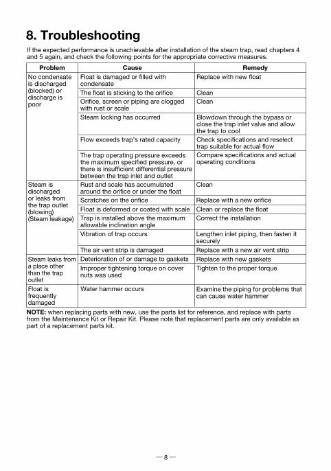
8. TroubleshootingIf the expected performance is unachievable after installation of the steam trap, read chapters 4and 5 again, and check the following points for the appropriate corrective measures.
ProblemNo condensate is discharged (blocked) ordischarge is poor
Steam is discharged or leaks fromthe trap outlet(blowing)(Steam leakage)
Steam leaks froma place other than the trapoutlet
Float is damaged or filled with condensate
The trap operating pressure exceeds the maximum specified pressure, or there is insufficient differential pressure between the trap inlet and outlet
Compare specifications and actual operating conditions
Steam locking has occurred
Flow exceeds trap’s rated capacity
Blowdown through the bypass or close the trap inlet valve and allow the trap to coolCheck specifications and reselect trap suitable for actual flow
Clean
Deterioration of or damage to gaskets Replace with new gaskets
Float is frequently damaged
Water hammer occurs Examine the piping for problems that can cause water hammer
Scratches on the orifice Replace with a new orificeFloat is deformed or coated with scale Clean or replace the floatTrap is installed above the maximum allowable inclination angle
Correct the installation
Vibration of trap occurs Lengthen inlet piping, then fasten it securely
The air vent strip is damaged Replace with a new air vent strip
Replace with new floatCause Remedy
The float is sticking to the orifice
Tighten to the proper torque
Orifice, screen or piping are clogged with rust or scale
Rust and scale has accumulated around the orifice or under the float
Clean Clean
NOTE: when replacing parts with new, use the parts list for reference, and replace with parts from the Maintenance Kit or Repair Kit. Please note that replacement parts are only available as part of a replacement parts kit.
Improper tightening torque on cover nuts was used

9. Express Limited WarrantySubject to the limitations set forth below, TLV Corporation, a North Carolina corporation (“TLV”) warrants that products which are sold by it or TLV International, Inc., a Japanese corporation (“TII”), which products (the “Products”) are designed and manufactured by TLV Co., Ltd., a Japanese corporation (“TLVJ”), conform to the specifications published by TLV for the corresponding part numbers (the “Specifications”) and are free from defective workmanship and materials. With regard to products or components manufactured by unrelated third parties (the “Components”), TLV provides no warranty other than the warranty from the third party manufacturer(s).
Duration Of WarrantyThis warranty is effective for a period of the earlier of: ( i ) three (3) years after delivery of Products to the first end user in the case of sealed SST-Series Products for use in steam pressure service up to 650 psig; (ii) two (2) years after delivery of Products to the first end user in the case of PowerTrap® units; or (iii) one (1) year afterdelivery of Products to the first end user in the case of all other Products. Notwithstanding the foregoing, asserting a claim under this warranty must be brought by the earlier of one of the foregoing periods, as applicable, or within five (5) years after the date of delivery to the initial buyer if not sold initially to the first end user.
ANY IMPLIED WARRANTIES NOT NEGATED HEREBY WHICH MAY ARISE BY OPERATION OF LAW, INCLUDING THE IMPLIED WARRANTIES OF MERCHANTABILITY AND FITNESS FOR A PARTICULAR PURPOSE AND ANY EXPRESS WARRANTIES NOT NEGATED HEREBY, ARE GIVEN SOLELY TO THE INITIAL BUYER AND ARE LIMITED IN DURATION TO ONE (1) YEARFROM THE DATE OF SHIPMENT BY TLV.
Exclusive RemedyTHE EXCLUSIVE REMEDY UNDER THIS WARRANTY, UNDER ANY EXPRESS WARRANTY OR UNDER ANY IMPLIED WARRANTIES NOT NEGATED HEREBY (INCLUDING THE IMPLIED WARRANTIES OF MERCHANTABILITY AND FITNESS FOR A PARTICULAR PURPOSE), IS REPLACEMENT; PROVIDED: (a) THE CLAIMED DEFECT IS REPORTED TO TLV IN WRITING WITHIN THE APPLICABLE WARRANTY PERIOD, INCLUDING A DETAILED WRITTEN DESCRIPTION OF THE CLAIMED DEFECT AND HOW AND WHEN THE CLAIMED DEFECTIVE PRODUCT WAS USED; AND (b) THE CLAIMED DEFECTIVE PRODUCT AND A COPY OF THE PURCHASE INVOICE IS RETURNED TO TLV, FREIGHT AND TRANSPORTATION COSTS PREPAID, UNDER A RETURN MATERIAL AUTHORIZATION AND TRACKING NUMBER ISSUED BY TLV. ALL LABOR COSTS, SHIPPING COSTS, AND TRANSPORTATION COSTS ASSOCIATED WITH THE RETURN OR REPLACEMENT OF THE CLAIMED DEFECTIVE PRODUCT ARE SOLELY THE RESPONSIBILITY OF BUYER OR THE FIRST END USER. TLV RESERVES THE RIGHT TO INSPECT ON THE FIRST END USER'S SITE ANY PRODUCTS
Exceptions To WarrantyThis warranty does not cover defects or failures caused by:1. improper shipping, installation, use, handling, etc., by other than TLV or service
representatives authorized by TLV; or2. dirt, scale or rust, etc.; or3. improper disassembly and reassembly, or inadequate inspection and maintenance by other
than TLV or service representatives authorized by TLV; or4. disasters or forces of nature; or5. abuse, abnormal use, accidents or any other cause beyond the control of TLV; or6. improper storage, maintenance or repair; or7. operation of the Products not in accordance with instructions issued with the Products or
with accepted industry practices; or8. use for a purpose or in a manner for which the Products were not intended; or9. use of the Products in a manner inconsistent with the Specifications; or
10. failure to follow the instructions contained in the TLV Instruction Manual for the Product.

CLAIMED TO BE DEFECTIVE BEFORE ISSUING A RETURN MATERIAL AUTHORIZATION. SHOULD SUCH INSPECTION REVEAL, IN TLV’S REASONABLE DISCRETION, THAT THE CLAIMED DEFECT IS NOT COVERED BY THIS WARRANTY, THE PARTY ASSERTING THIS WARRANTY SHALL PAY TLV FOR THE TIME AND EXPENSES RELATED TO SUCH ON-SITE INSPECTION.
Exclusion Of Consequential And Incidental DamagesIT IS SPECIFICALLY ACKNOWLEDGED THAT THIS WARRANTY, ANY OTHER EXPRESS WARRANTY NOT NEGATED HEREBY, AND ANY IMPLIED WARRANTY NOT NEGATED HEREBY, INCLUDING THE IMPLIED WARRANTIES OF MERCHANTABILITY AND FITNESS FOR A PARTICULAR PURPOSE, DO NOT COVER, AND NEITHER TLV, TII NOR TLVJ WILL INANY EVENT BE LIABLE FOR, INCIDENTAL OR CONSEQUENTIAL DAMAGES, INCLUDING, BUT NOT LIMITED TO LOST PROFITS, THE COST OF DISASSEMBLY AND SHIPMENT OF THE DEFECTIVE PRODUCT, INJURY TO OTHER PROPERTY, DAMAGE TO BUYER’S OR THE FIRST END USER’S PRODUCT, DAMAGE TO BUYER’S OR THE FIRST END USER’S PROCESSES, LOSS OF USE, OR OTHER COMMERCIAL LOSSES. WHERE, DUE TO OPERATION OF LAW, CONSEQUENTIAL AND INCIDENTAL DAMAGES UNDER THIS WARRANTY, UNDER ANY OTHER EXPRESS WARRANTY NOT NEGATED HEREBY OR UNDER ANY IMPLIED WARRANTY NOT NEGATED HEREBY (INCLUDING THE IMPLIED WARRANTIES OF MERCHANTABILITY AND FITNESS FOR A PARTICULAR PURPOSE) CANNOT BE EXCLUDED, SUCH DAMAGES ARE EXPRESSLY LIMITED IN AMOUNT TO THE PURCHASE PRICE OF THE DEFECTIVE PRODUCT. THIS EXCLUSION OF CONSEQUENTIAL AND INCIDENTAL DAMAGES, AND THE PROVISION OF THIS WARRANTY LIMITING REMEDIES HEREUNDER TO REPLACEMENT, ARE INDEPENDENT PROVISIONS, AND ANY DETERMINATION THAT THE LIMITATION OF REMEDIES FAILS OF ITS ESSENTIAL PURPOSE OR ANY OTHER DETERMINATION THAT EITHER OF THE ABOVE REMEDIES IS UNENFORCEABLE, SHALL NOT BE CONSTRUED TO MAKE THE OTHER PROVISIONS UNENFORCEABLE.
Exclusion Of Other WarrantiesTHIS WARRANTY IS IN LIEU OF ALL OTHER WARRANTIES, EXPRESS OR IMPLIED, AND ALL OTHER WARRANTIES, INCLUDING BUT NOT LIMITED TO THE IMPLIED WARRANTIES OF MERCHANTABILITY AND FITNESS FOR A PARTICULAR PURPOSE, ARE EXPRESSLY DISCLAIMED.
SeverabilityAny provision of this warranty which is invalid, prohibited or unenforceable in any jurisdiction shall, as to such jurisdiction, be ineffective to the extent of such invalidity, prohibition orunenforceability without invalidating the remaining provisions hereof, and any such invalidity, prohibition or unenforceability in any such jurisdiction shall not invalidate or render unenforceable such provision in any other jurisdiction.
13901 South Lakes Drive, Charlotte, NC 28273-6790, U.S.A.Tel: [1]-704-597-9070 Fax: [1]-704-583-1610

Printed on recycled paper.
881 Nagasuna, Noguchi, Kakogawa, Hyogo 675-8511, Japan
Manufacturer: Tel: [81]-(0)79-422-1122Fax: [81]-(0)79-422-0112
Rev. 2/2018 (M)PAC-65359-a