sizing safety valves for supercritical steam boilers
TRANSCRIPT

IChemE SYMPOSIUM SERIES NO. 153 # 2007 Crown Copyright
SIZING SAFETY VALVES FOR SUPERCRITICAL STEAM BOILERS†
J A Hare1,3 and G Hawkins2
1Health and Safety Laboratory, Process Safety Section2Health and Safety Executive, Hazardous Installations Directorate, Chemical Industries3Contact details: HSL, Harpur Hill, Buxton, Derbyshire, SK17 9JN, UK; Tel.: þ44 (0)1298 218125, e-mail: [email protected]
There is considerable interest in the improved efficiency afforded by the operation of steam boilers
at supercritical steam temperatures and pressures i.e. pressures above 220 bar and temperatures
above 3748C.
Steam boilers are normally fitted with safety valves to protect the boiler from over-pressurisation
and standard methods are available for the sizing of safety valves for steam flow, using either “gas
flow equations” with property data for steam or using simplified “steam flow equations”. The
methods are documented in the following standards: BS EN ISO 4126-1, various German standards
and API 520.
What methods should be used to size the safety valve for a supercritical steam boiler? The avail-
able literature on supercritical pressure relief, particularly involving steam, will be reviewed.
Safety valve sizing calculations were performed at various supercritical pressures and tempera-
tures. Reference methods were available using the rigorous Homogeneous Equilibrium Method
(HEM) calculation method and the HEM using the Omega method (simple Equation of State).
These methods were compared with the methods outlined in the standards with various assumptions.
Recommendations are made for the sizing of safety valves for supercritical steam boilers.
KEYWORDS: safety valve sizing, supercritical steam, steam boilers, standards
INTRODUCTIONThere is considerable interest in the improved efficiencyafforded by the operation of steam boilers at supercriticalsteam temperatures and pressures i.e. pressures above 220bar and temperatures above 3748C. Steam boilers are nor-mally fitted with safety valves to protect the boiler fromover-pressurisation and standard methods are available forthe sizing of safety valves for steam flow, using either“gas flow equations” with property data for steam or usingsimplified “steam flow equations”. The methods are docu-mented in the various standards. This paper considerswhat methods should be used to size the safety valve for asupercritical steam boiler. In this paper, to avoid any con-fusion between terms, supercritical always refers to the ther-modynamic state and choked conditions correspond to themaximum mass flow rate.
BASIC THERMODYNAMICS AND FLUID
MECHANICSFlow a supercritical fluid through a safety valve will bedependent on a number of factors. It will normally reach acondition whereby lowering the downstream pressure for agiven fluid pressure and temperature at the safety valveinlet will not lead to an increase in velocity of the escapingfluid. Under these conditions the flow is known as “choked”flow and the safety valve acts as the “choke” point in thesystem. Determining the maximum mass flux along an isen-tropic path identifies the choke. For supercritical fluids, the
†# 2007 Crown Copyright. This article is published with the permission o
1
choke conditions may occur in the superheated vapourregion or the sub-cooled liquid region. Where the relievingpressure and temperature lie relative to the saturated vapourand liquid lines on an entropy/temperature plot determineswhere the choke will lie (see Figure 1). As the pressure fallsthe fluid will follow a line of constant entropy. For super-critical steam there will generally be only one phase: thesupercritical fluid (choke in superheated vapour region) orthe liquid phase (choke in sub cooled liquid region). Isentro-pic expansions of sub-critical superheated steam can givechokes in the two-phase region.
What follows is generally applicable to cases wherethe choke is in the superheated vapour region. The use ofthe isentropic coefficient k or similar term is only validwhere the choke is in the superheated region. The supercriti-cal fluid is effectively being treated as a non-ideal hightemperature and pressure gas. Therefore where the chokelies relative to the boundary between the two-phase andsupercritical region is of vital importance. For water/steam, thermodynamic data in the form of tables andentropy – temperature diagrams are readily available,which allow the boundary between regions to be identified.The section on Gas Flow and Standard Methods discusseshow the choke temperature and choke pressure ratios maybe estimated from the isentropic coefficient.
HEM METHODSThe Homogeneous Equilibrium Model (HEM) (Fisher1992) assumes uniform mixing across the flow area and
f the controller of HMSO and the Queen’s Printer for Scotland

Figure 1. Entropy – temperature graph for water/steam
Table 1. Choke pressure and temperature ratios
Isentropic
coefficient
(k)
Choke
pressure
ratio (hc)
Choke
temperature
ratio (uc)
Dimensionless
mass flux
(Gchoke�)
1.135 0.578 0.937 0.636
1.3 0.546 0.870 0.667
IChemE SYMPOSIUM SERIES NO. 153 # 2007 Crown Copyright
both thermodynamic and mechanical equilibrium. The rig-orous HEM calculation uses physical property data toevaluate the isentropic expansion from an initial supercriti-cal pressure and supercritical temperature. The mass flux(G) when calculated using equation (1) goes through amaximum at the choke pressure (Pchoke). This maximumflux is the choke mass flux (Gchoke).
G ¼ ((2(ho � h))1=2)=v (1)
The safety valve area (A) is then calculated usingequation (2), which includes the required mass flow rate(Qm). Note in safety valve sizing, Qm is normally given in(kg h21) and A in (mm2). The discharge coefficient (Kdr)is the actual flow capacity divided by the theoretical flowcapacity. In the example calculations in this paper the dis-charge coefficient was taken to be 1.0.
A ¼ Qm106={3600 KdrGchoke} (2)
The HEM can be evaluated approximately using theOmega method (Leung 1996). The value of Omega (v)can be calculated at any pressure (P) using an Equation ofState (3). A single isentropic expansion is required to gener-ate the Equation of State; generally the expansion is to 0.9 or0.7 of the original pressure.
v ¼ ((v=vo)� 1)=((Po=P)� 1) (3)
The Omega method, implemented using a spread-sheet, can then be used to calculate the choke pressureratio (hc), hence the choke pressure (Pchoke) and also thechoke mass flux (Gchoke). To obtain hc, its value is variedusing a solver so that equation (4) is satisfied. Pchoke isthen obtained using equation (5). Gchoke
� is obtained usingequation (6) and Gchoke with equation (7). The safetyvalve area (A) is then calculated using equation (2). Notethat equation (7) can be used to back calculate an equivalent
2
dimensionless mass flux value (Gchoke�) for the rigorous
HEM calculation.
h2c þ (v2 � 2v)(1� hc)2 þ 2v2lnhc
þ 2v2(1� hc) ¼ 0 (4)
Pchoke ¼ Pohc (5)
Gchoke� ¼ (hc=v1=2) (6)
Gchoke ¼ (Po=vo)1=2Gchoke� (7)
GAS FLOW AND STANDARD METHODSFor gas flow, a dimensionless mass flux (Gchoke
�) can bedefined similar to that used in the Omega method. Gchoke
�
can be estimated from the isentropic coefficient k usingequation (8). Similar terms, to the dimensionless massflux, occur in various standards. The terms can all be calcu-lated from Gchoke
� or k. The sizing equations from ISO stan-dard 4126-1 are given in the next subsection, including anequation for the compressibility factor Z.
Gchoke� ¼ {k(2=(kþ 1))(kþ1)=(k�1)}1=2 (8)
Working with a k value enables the choke pressureratio (hc) and choke temperature ratio (uc) to be estimatedusing equations (9) and (10) based on gas flow theory(Lapple 1943). The values of both ratios and Gchoke
� arelisted in Table 1 for k values of 1.135 (for saturated
IChemE SYMPOSIUM SERIES NO. 153 # 2007 Crown Copyright
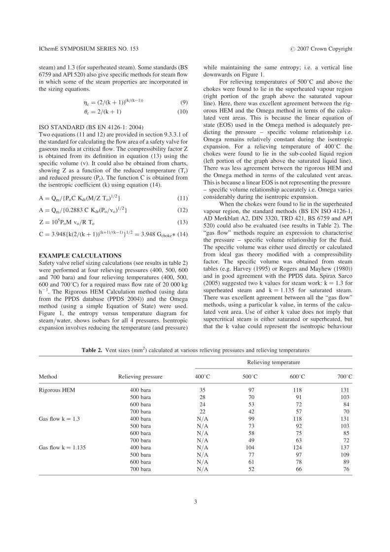
steam) and 1.3 (for superheated steam). Some standards (BS6759 and API 520) also give specific methods for steam flowin which some of the steam properties are incorporated inthe sizing equations.
hc ¼ (2=(kþ 1))(k=(k�1)) (9)
uc ¼ 2=(kþ 1) (10)
ISO STANDARD (BS EN 4126-1: 2004)Two equations (11 and 12) are provided in section 9.3.3.1 ofthe standard for calculating the flow area of a safety valve forgaseous media at critical flow. The compressibility factor Zis obtained from its definition in equation (13) using thespecific volume (v). It could also be obtained from charts,showing Z as a function of the reduced temperature (Tr)and reduced pressure (Pr). The function C is obtained fromthe isentropic coefficient (k) using equation (14).
A ¼ Qm={PoC Kdr(M=Z To)1=2} (11)
A ¼ Qm={0:2883 C Kdr(Po=vo)1=2} (12)
Z ¼ 105PoM vo=R To (13)
C ¼ 3:948{k(2=(kþ 1))(kþ1)=(k�1)}1=2 ¼ 3:948 Gchoke� (14)
EXAMPLE CALCULATIONSSafety valve relief sizing calculations (see results in table 2)were performed at four relieving pressures (400, 500, 600and 700 bara) and four relieving temperatures (400, 500,600 and 7008C) for a required mass flow rate of 20 000 kgh21. The Rigorous HEM Calculation method (using datafrom the PPDS database (PPDS 2004)) and the Omegamethod (using a simple Equation of State) were used.Figure 1, the entropy versus temperature diagram forsteam/water, shows isobars for all 4 pressures. Isentropicexpansion involves reducing the temperature (and pressure)
Table 2. Vent sizes (mm2) calculated at various
Method Relieving pressure 40
Rigorous HEM 400 bara
500 bara
600 bara
700 bara
Gas flow k ¼ 1.3 400 bara N
500 bara N
600 bara N
700 bara N
Gas flow k ¼ 1.135 400 bara N
500 bara N
600 bara N
700 bara N
3
while maintaining the same entropy; i.e. a vertical linedownwards on Figure 1.
For relieving temperatures of 5008C and above thechokes were found to lie in the superheated vapour region(right portion of the graph above the saturated vapourline). Here, there was excellent agreement between the rig-orous HEM and the Omega method in terms of the calcu-lated vent areas. This is because the linear equation ofstate (EOS) used in the Omega method is adequately pre-dicting the pressure – specific volume relationship i.e.Omega remains relatively constant during the isentropicexpansion. For a relieving temperature of 4008C thechokes were found to lie in the sub-cooled liquid region(left portion of the graph above the saturated liquid line).There was less agreement between the rigorous HEM andthe Omega method in terms of the calculated vent areas.This is because a linear EOS is not representing the pressure– specific volume relationship accurately i.e. Omega variesconsiderably during the isentropic expansion.
When the chokes were found to lie in the superheatedvapour region, the standard methods (BS EN ISO 4126-1,AD Merkblatt A2, DIN 3320, TRD 421, BS 6759 and API520) could also be evaluated (see results in Table 2). The“gas flow” methods require an expression to characterisethe pressure – specific volume relationship for the fluid.The specific volume was either used directly or calculatedfrom ideal gas theory modified with a compressibilityfactor. The specific volume was obtained from steamtables (e.g. Harvey (1995) or Rogers and Mayhew (1980))and in good agreement with the PPDS data. Spirax Sarco(2005) suggested two k values for steam work: k ¼ 1.3 forsuperheated steam and k ¼ 1.135 for saturated steam.There was excellent agreement between all the “gas flow”methods, using a particular k value, in terms of the calcu-lated vent area. Use of either k value does not imply thatsupercritical steam is either saturated or superheated, butthat the k value could represent the isentropic behaviour
relieving pressures and relieving temperatures
Relieving temperature
08C 5008C 6008C 7008C
35 97 118 131
28 70 91 103
24 53 72 84
22 42 57 70
/A 99 118 131
/A 73 92 103
/A 58 75 85
/A 49 63 72
/A 104 124 137
/A 77 97 109
/A 61 78 89
/A 52 66 76

Figure 2. Dimensionless mass flux
IChemE SYMPOSIUM SERIES NO. 153 # 2007 Crown Copyright
of the fluid. Using any of the “gas flow” methods with accu-rate specific volume data and a k value of 1.3, the calculatedflow areas were slightly higher than the reference methods.With accurate specific volume data and a k value of 1.135,the calculated flow areas were higher than the referencemethods but were not unduly conservative. “Steam flow”methods rely on the relief pressure and a superheat correc-tion factor. These methods were not used in the calculations,as superheat makes little sense for supercritical steam, asthere is no saturation temperature.
DISCUSSION AND RECOMMENDATIONSFigure 2 shows the dimensionless mass flux (Gchoke
�) versusrelieving pressure for a range of relieving temperatures. Forrelieving temperatures of 5008C and above, there is lessGchoke
� variation at low pressure and also Gchoke� increases
Figure 3. Chok
4
with pressure and decreases with temperature. Gchoke�
values could be obtained using either the rigorous HEM orthe Omega method. For relieving temperatures of 5008Cand above, using a k value of 1.3 in the gas flow equations,is more representative of Gchoke
� than using a k value of1.135. The reason for the k ¼ 1.3 predictions being moreaccurate is now clear. For a relieving temperature of 4008C,the Gchoke
� values (obtained using the rigorous HEM) weremuch higher, this causes the calculated vent sizes to bemuch smaller. Gas flow equation methods would not bevalid for this relieving temperature; clearly the choke is inthe sub-cooled liquid region. Gchoke
� seems to be still increas-ing with pressure and decreasing with temperature. The graphalso shows the Gchoke
� for liquid flow; use of a liquid flowequation would over-predict the dimensionless mass flux.
Figure 3 shows the choke pressure ratio (hc) versusrelieving pressure for a range of relieving temperatures.
e pressure ratio

IChemE SYMPOSIUM SERIES NO. 153 # 2007 Crown Copyright
For the HEM, for relieving temperatures of 5008C andabove, there is less hc variation at low pressure and alsohc decreases with pressure and increases with temperature.For relieving temperatures of 5008C and above, using a kvalue of 1.3 in the gas flow equations is more representativeof hc than using a k value of 1.135. For a relieving tempera-ture of 4008C, the hc values were significantly lower. Use ofgas flow equation methods would not be valid for this reliev-ing temperature; clearly the choke is in the sub-cooled liquidregion. hc seems to be still decreasing with pressure andincreasing with temperature. The graph also shows the hc
for liquid flow, use of a liquid flow equation would underpredict the choke pressure ratio.
Figure 4 shows the choke temperature ratio (uc)versus relieving pressure for a range of relieving tempera-tures. uc values were obtained using the rigorous HEM.There is more uc variation at low temperature: for a relievingtemperature of 4008C uc decreases with pressure, whereasfor a relieving temperature of 5008C uc increases withpressure. For relieving temperatures of 6008C and above,using a k value of 1.3, in the gas flow equations, is morerepresentative of uc than using a k value of 1.135.
Supercritical steam boilers are finding increasingapplication in the power generation sector. They are usedto achieve higher operating efficiencies. Pressures are typi-cally in the range to 220 to 420 bara and mass flowsaround 150,000 kg h21. Use of chrome containing steelsallows steam temperature up to 6208C, whilst nickel basedalloys can work up to 7208C.
The recommended method of approach is to examinethe relieving pressure and relieving temperature on theentropy temperature diagram:
. If it lies above the saturated vapour line then the chokewill occur in the superheated vapour region. For accu-rate work the rigorous HEM or the Omega method(based on an EOS) can be used to determine the massflux. Reasonable predictions for the mass flux can also
Figure 4. Choke
5
be achieved using gas flow equations with k ¼ 1.3 andaccurate specific volume data.
. If it lies above the saturated liquid line vapour then thechoke will occur in the sub-cooled liquid region. Therigorous HEM is generally the only method availableto predict the mass flux. Use of a liquid flow equationmay over predict the mass flux.
. If it lies directly above the critical point, or above thesaturated vapour line but at a temperature below5008C, it would be prudent to use the rigorous HEM.Further work is in progress to better define the applica-bility of different methods in this region.
UNITS AND SYMBOLSA ¼ flow area of safety valve (mm2)C ¼ function of isentropic coefficientG ¼ mass flux (kg m22 s21)Gchoke ¼ maximum mass flux at choke pressure
(kg m22 s21)Gchoke
� ¼ dimensionless mass flux at choke pressureho ¼ initial enthalpy at starting pressure (J kg21)h ¼ enthalpy at current pressure (J kg21)k ¼ isentropic coefficientKdr ¼ discharge coefficientM ¼ molar mass (kg kmol21)Po ¼ starting/relieving pressure (bara)P ¼ current pressure (bara)Pchoke ¼ choke pressure (bara)Pr ¼ reduced pressureQm ¼ required mass flowrate (kg h21)R ¼ universal gas constantTo ¼ relieving temperature (K)T ¼ inlet temperature (K)Tchoke ¼ choke temperature (K)Tr ¼ reduced temperaturev ¼ specific volume at current pressure (m3 kg21)
temperature ratio

IChemE SYMPOSIUM SERIES NO. 153 # 2007 Crown Copyright
vo ¼ initial specific volume at starting pressure (m3 kg21)Z ¼ compressibility factorv ¼ Omega parameterhc ¼ choke pressure ratiouc ¼ choke temperature ratio
REFERENCES1. AD Merkblatt A2 Pressure Vessel Equipment safety
devices against excess pressure – safety valves
2. API RP 520 “Sizing, Selection, and Installation of
Pressure-Relieving Devices in Refineries Part 1 – Sizing
and Selection” 7th edition January 2000
3. BSI EN ISO 4126-1: 2004 “Safety devices for protection
against excessive pressure – Part 1: Safety valves”
4. BS 6759 Safety Valves Parts 1–3, 1984
5. DIN 3320-1: 1984, Safety valves; safety shut-off valves;
definitions, sizing, marking
6. Fisher HG et al “Emergency Relief System Design using
DIERS technology” Chapter II, DIERS/AIChE, 1992
6
7. Harvey AH “Thermodynamic Properties of Water: Tabula-
tion from the IAPWS Formulation 1995 for the Thermo-
dynamic Properties of Ordinary Water Substance for
General and Scientific Use”, NIST web guide, 1995
8. Lapple “Isothermal and Adiabatic Flow of Compressible
Fluids” Trans AIChE Vol 39 p385–432,1943
9. Leung “Easily Size Relief Devices and Piping for
Two-Phase Flow” Chemical Engineering Progress, p28
December 1996
10. Physical Property Data Service (PPDS) for Windows,
v3.1.4 TUV NEL Ltd, 2004
11. Rogers GFC & Mayhew “Thermodynamic and Transport
Properties of Fluid” 3rd edition, 1980
12. Spirax Sarco, “Steam Engineering Learning Modules –
Module 9.4 Safety Valve Sizing”, 2005
13. TRD 421, Technical Equipment for Steam Boilers
Safeguards against excessive pressure – safety valves for
boilers of groups I, III & IV