sixth framework programme sustainable energy systems
TRANSCRIPT
SIXTH FRAMEWORK PROGRAMME Sustainable Energy Systems
NETWORK OF EXCELLENCE
Contract No SES6-CT-2004-502630
Safety of Hydrogen as an Energy Carrier
Report on existing know-how in the field of Material Compatibility
Deliverable No97 (WP 18)
Lead Participant: INASMET-Tecnalia (INASMET) Partners Contributing: Air Liquide (AL)
BMW Forschung und Technik GMBH (BMW) Det Norske Veritas (DNV) Federal Institute for Materials Research and Testing (BAM) Fraunhofer-Institut für Chemische Technologie, ICT. (Fh-ICT) Forschungszentrum Karlsruhe (FZK) Risoe National Laboratory (Risoe) Russian Research Centre Kurchatov Institute RU (KI) StatoilHydro ASA (NH) Universita degli studi di Pisa (UNIPI)
Dissemination Level: CO (Confidential, only for members of the consortium (including EC) Document Version: Version No 1.0 Date of preparation: 30.01.2008 Co-funded by the European Commission within the Sixth Framework Programme (2002-2006)
HYSAFE – Safety of Hydrogen As an Energy Carrier
Material Compatibility and Structural Integrity - Page 2 of 39 – D97 INASMET V.1.0
CONTENTS 1. INTRODUCTION ............................................................................................................... 4 2. HYDROGEN DAMAGE..................................................................................................... 5 3. STUDY BASIS.................................................................................................................... 9 4. EXISTING KNOW-HOW................................................................................................. 10 5. conclusions and further steps ............................................................................................. 23 6. REFERENCES .................................................................................................................. 24 Annex 1 – Description of experimental facilities……………………………………………...25 Annex 2 – References of experimental facilities…………………………………….………...33

HYSAFE – Safety of Hydrogen As an Energy Carrier
Material Compatibility and Structural Integrity - Page 3 of 39 – D97 INASMET V.1.0

HYSAFE – Safety of Hydrogen As an Energy Carrier
Material Compatibility and Structural Integrity - Page 4 of 39 – D97 INASMET V.1.0
1. INTRODUCTION Hydrogen is believed to be the future source of energy and a “hydrogen economy” is a strong possibility within the next 50 years. In such a scenario, large scale production, storage, transportation and use of hydrogen become necessary. Hydrogen components and hydrogen systems commonly involve a wide variety of materials, both metals and non-metals (such as polymers). Each material that is involved should be carefully evaluated for its use in the design, operating, and emergency conditions to which it will be exposed. The selection of a material that is suitable for use in hydrogen system involves several factors. Some considerations involved in the choice of a material to be used in a hydrogen system include the following ones:
• Compatibility with hydrogen (with concerns such as hydrogen embrittlement, hydrogen attack, hydriding, porosity, permeation and diffusion);
• Compatibility with adjoining materials; • Compatibility with the conditions of use; • Compatibility with the surrounding environment or exposure; • Toxicity; • Failure mode; • Ability to fabricate into the desired form; • Economics; • Availability.
Most of these considerations are common for the selection of a material for any purpose. However, the first one is unique to hydrogen, and the next two are important for liquid hydrogen applications, because of the low temperature involved (20K). Materials’ problems caused by hydrogen damage could limit the progress of such an economy. Hydrogen may be picked up by metals during melting, casting, shaping and fabrication. They are also exposed to hydrogen during their service life. Materials susceptible to hydrogen damage have ample opportunities to be degraded during all these stages. Taking this into account and also the fact that in many different events and from various other relevant EC projects (e.g. StorHy, NaturalHy) there have been several indications, especially by industry representatives, that answering questions in the field of material compatibility has a high priority, Workpackage 18 and specifically Deliverable 97 tries to summarize existing knowledge in the field for all relevant materials, and especially the behaviour of new compound materials.
HYSAFE – Safety of Hydrogen As an Energy Carrier
Material Compatibility and Structural Integrity - Page 5 of 39 – D97 INASMET V.1.0
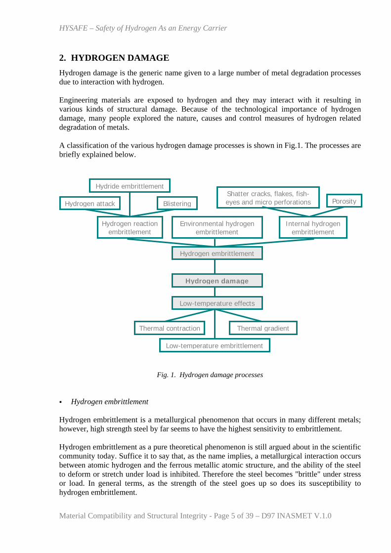
2. HYDROGEN DAMAGE Hydrogen damage is the generic name given to a large number of metal degradation processes due to interaction with hydrogen. Engineering materials are exposed to hydrogen and they may interact with it resulting in various kinds of structural damage. Because of the technological importance of hydrogen damage, many people explored the nature, causes and control measures of hydrogen related degradation of metals. A classification of the various hydrogen damage processes is shown in Fig.1. The processes are briefly explained below.
Fig. 1. Hydrogen damage processes Hydrogen embrittlement
Hydrogen embrittlement is a metallurgical phenomenon that occurs in many different metals; however, high strength steel by far seems to have the highest sensitivity to embrittlement. Hydrogen embrittlement as a pure theoretical phenomenon is still argued about in the scientific community today. Suffice it to say that, as the name implies, a metallurgical interaction occurs between atomic hydrogen and the ferrous metallic atomic structure, and the ability of the steel to deform or stretch under load is inhibited. Therefore the steel becomes "brittle" under stress or load. In general terms, as the strength of the steel goes up so does its susceptibility to hydrogen embrittlement.
Hydrogen embrittlement
Hydrogen damage
Hydride embrittlement
Hydrogen attack
Environmental hydrogen embrittlement
Internal hydrogen embrittlement
Hydrogen reaction embrittlement
Porosity
Thermal gradient Thermal contraction
Low-temperature embrittlement
Low-temperature effects
BlisteringShatter cracks, flakes, fish-eyes and micro perforations
HYSAFE – Safety of Hydrogen As an Energy Carrier
Material Compatibility and Structural Integrity - Page 6 of 39 – D97 INASMET V.1.0
So, hydrogen embrittlement occurs when hydrogen or hydrogen compounds permeate into the lattice structure of the material. At the atomic level, for embrittlement to occur, hydrogen molecules must first dissociate into atoms before they can diffuse into the metallic structure. At temperatures close to ambient, a number of metallic materials are susceptible to hydrogen embrittlement, particularly those with a body-centred cubic crystal lattice structure. This is a particular problem with many ferritic steels if they are subjected to mechanical stresses. The process takes place on freshly generated metallic surfaces that are likely to form on surface defects or other stress raisers as a result of stress-induced local plastic deformation processes. Impurities such as hydrogen sulphide dissociate into atomic hydrogen even more easily than molecular hydrogen. Sources of hydrogen causing embrittlement have been encountered in the making of steel, in processing parts, in welding, in storage or containment of hydrogen gas, and related to hydrogen as a contaminant in the environment that is often a by-product of general corrosion. Hydrogen entry, the obvious pre-requisite of embrittlement, can be facilitated in a number of ways summarized below:
By some manufacturing operations such as welding, electroplating, phosphating and pickling; if a material subject to such operations is susceptible to hydrogen embrittlement then a final, baking heat treatment to expel any hydrogen is employed.
As a by-product of corrosion reaction such as in circumstances when the hydrogen production reaction acts as the cathodic reaction since some of the hydrogen produced may enter the metal in atomic form rather than be all evolved as a gas into the surrounding environment. In this situation, cracking failures can often be thought of as a type of stress corrosion cracking (SCC). If the presence of hydrogen sulphide causes entry of hydrogen into the component, the cracking phenomenon is often termed “sulphide stress cracking (SSC)”.
The use of cathodic protection for corrosion protection if the process is not properly controlled.
• Hydrogen reaction embrittlement The hydrogen chemically reacts with a constituent of the metal to form a new microstructural element of phase such as a hydride or gas bubbles (“blistering”).
- Hydride embrittlement In hydride forming metals like titanium, zirconium and vanadium, hydrogen absorption causes severe embrittlement. At low concentrations of hydrogen, below the solid solubility limit, stress-assisted hydride formation causes the embrittlement which is enhanced by slow straining. At hydrogen concentrations above the solubility limit, brittle hydrides are precipitated on slip planes and cause severe embrittlement. This latter kind of embrittlement is encouraged by increased strain-rates, decreased temperature and by the presence of notches in the material. A ductile-to-brittle transition is produced when the test temperature is lowered.
- Blistering Atomic hydrogen diffusing through metals may collect at internal defects like inclusions and laminations and form molecular hydrogen. High pressures may be
HYSAFE – Safety of Hydrogen As an Energy Carrier
Material Compatibility and Structural Integrity - Page 7 of 39 – D97 INASMET V.1.0
built up at such locations due to continued absorption of hydrogen leading to blister formation, growth and eventual bursting of the blister.
- Hydrogen attack At temperatures above 200ºC, many low-alloyed structural steels can suffer from another hydrogen-related embrittlement phenomenon known as hydrogen attack. It is a non-reversible degradation of the steel microstructure caused by a chemical reaction between diffusing hydrogen and the carbide particles in the steel, resulting in the formation of methane. Severity of the hydrogen attack increases with increasing temperature and pressure.
• Internal hydrogen embrittlement Internal hydrogen embrittlement means that hydrogen is introduced into the metal during its processing, e.g., chemical reactions with water to form metal oxide and liberate hydrogen. It is a phenomenon that my lead to the structural failure of material that never has been exposed to hydrogen before. Internal cracks are initiated showing a discontinuous growth. Not more than 0.1-10 ppm hydrogen in the average are involved. The effect is observed in the temperature range between -100 and +100ºC and is most severe near room temperature.
- Shatter cracks, flakes, fish-eyes and micro perforations Flakes and shatter cracks are internal fissures seen in large forgings. Hydrogen picked up during melting and casting segregates at internal voids and discontinuities and produces these defects during forging. Fish-eyes are bright patches resembling eyes of fish seen on fracture surfaces, generally of weldments. Hydrogen enters the metal during fusion-welding and produces this defect during subsequent stressing. On the other hand, steel containment vessels exposed to extremely high hydrogen pressures develop small fissures or micro perforations through which fluids may leak. - Porosity In metals like iron & steel, aluminum and magnesium whose hydrogen solubility decrease with temperature, liberation of excess hydrogen during cooling from the melt, (in ingots and castings) produces gas porosity.
• Environmental hydrogen embrittlement Environmental hydrogen embrittlement means that the material was subjected to a hydrogen atmosphere, e.g. storage tanks. Absorbed and/or adsorbed hydrogen modifies the mechanical response of the material without necessarily forming a second phase. The effect occurs when the amount of hydrogen that is present, is more than the amount that is dissolved in the metal. The effect strongly depends on the stress imposed on the metal. It also maximizes at around room temperature.
HYSAFE – Safety of Hydrogen As an Energy Carrier
Material Compatibility and Structural Integrity - Page 8 of 39 – D97 INASMET V.1.0
• Low temperature effects
- Low temperature embrittlement Cryogenic temperatures can affect structural materials. With decreasing temperature, ultimate stress and yield stress increase for most metals, generally connected with a corresponding drop in fracture toughness which is a measure of the material’s ability to resist crack propagation. The lower the toughness, the smaller is the tolerable crack length. A material can change from ductile to brittle behaviour as soon as the temperature falls below it “nil-ductility temperature” which is sometimes considerably higher than the temperature of the cryogen. It is a particular problem in cryogenic equipment exposed to periodic temperature changes. Several accidents with failure of a cryogen storage tank have been traced to originate from cold embrittlement.
- Thermal contraction Low temperatures can also affect materials by thermal contraction. The thermal expansion coefficient is a function of temperature. For many materials, which are cooled down from room to cryogenic temperature, more than 90% of the total contraction experienced will have already taken place at 77K. Rule-of-thumb figures of thermal contraction are 0.3% in iron-based alloys, 0.4% in aluminium, or over 1% in many plastics. Cryogenic vessels of piping systems must account for this contraction to avoid large thermal stresses.
- Thermal gradient The components of a cryogenic system usually undergo a thermal gradient, some only during cool-down or warm-up phases, others even at steady state of operation. Strong gradients, particularly if non-linear, result in stresses which under certain circumstances may lead to rupture. Thermal gradients are of particular significance in systems with stratified two-phase flows of cryogenics.
HYSAFE – Safety of Hydrogen As an Energy Carrier
Material Compatibility and Structural Integrity - Page 9 of 39 – D97 INASMET V.1.0
3. STUDY BASIS The basis for this work has been information from partners involved in WP18. This means, their knowledge based on the experience in their companies or their participation in different technical committees etc., and their knowledge as far as what others do is concerned based on different information sources. Moreover, information found on the internet has been used. All of this in order to collect the existing available knowledge inside the HySafe consortium and also outside.
It is necessary to point out that, it has been detected that there are sources of information that could be accessible next year for the consortium as for example IEA Task 19 on Hydrogen Safety and that could contribute to widen the analysis of this deliverable.
HYSAFE – Safety of Hydrogen As an Energy Carrier
Material Compatibility and Structural Integrity - Page 10 of 39 – D97 INASMET V.1.0
4. EXISTING KNOW-HOW In order to obtain an overview of the existing knowledge in the field of material compatibility, it has been considered that the key is to bring together the information concerning the different testing procedures that are generally used to evaluate the different hydrogen damage processes already explained in the previous section. To do that, the partners have filled in a template the following concepts:
Test/Standard:
• Code • Title • Brief description • Facilities-Equipment/Partner: Reference of the equipment according to D9 (WP2).
This term tries to identify the facilities inside the consortium that are capable of performing any of the tests considered.
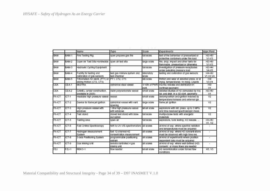
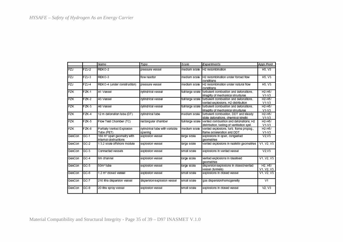
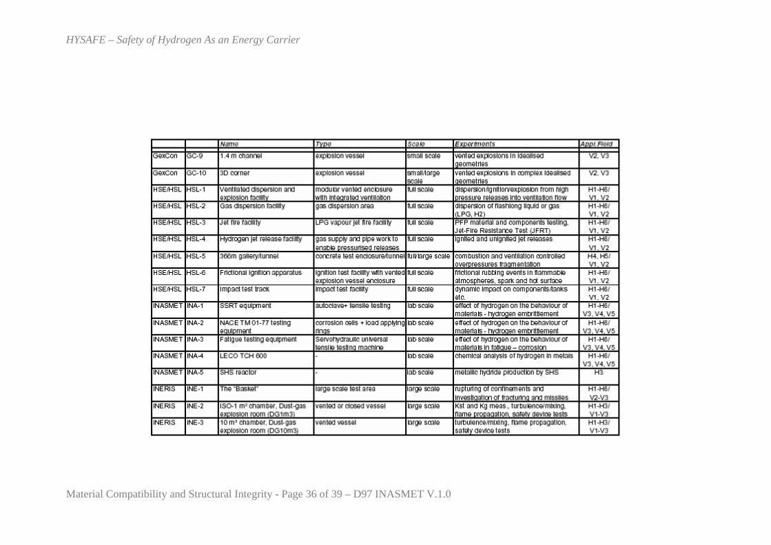
The reference of the equipment is that specified in D9 ‘Compilation of descriptions of experimental facilities’ of WP2 (Annex 2 of this deliverable only includes the list of references and the basic data). D9 includes the whole description of the equipment.
The reference and the description of those equipments mentioned in this deliverable that were not included in D9 ‘Compilation of descriptions of experimental facilities’ of WP2’ are included in Annex 1 of this deliverable.
Phenomena: Any of those described in the previous section.
Application field: The application fields correspond to the HySafe matrix
H1 - Production,
H2 - Transport and distribution, refuelling stations,
H3 - Storing H2,
H4 - Vehicles powered with H2,
H5 - Tunnels, public parking and private garage,
H6 - Utilisation, portable and stationary H2 based applications,
and
V1 - Hydrogen release, mixing, and distribution,
V2 - Fires, ignition and explosions,
V3 - Mitigation techniques,
V4 - Safety assessment and risk analysis,
V5 - Standardisation and legal requirements.
HYSAFE – Safety of Hydrogen As an Energy Carrier
Material Compatibility and Structural Integrity - Page 11 of 39 – D97 INASMET V.1.0
As a result it has been possible to identify the main standards and testing, the knowledge of the consortium in the field and also its capabilities. On the other hand the consortium has identified some other organizations that perform activites in the field.
4.1 Testing procedures
The main testing or standards identified have been the following ones: ISO 11114-4:2005
Phenomena studied: Hydrogen embrittlement. Application field: H2, H3/V1,V4,V5. Standard information:
Title: Transportable gas cylinders -- Compatibility of cylinder and valve materials with gas contents -- Part 4: Test methods for selecting metallic materials resistant to hydrogen embrittlement. Brief description: This part of ISO 11114 specifies test methods and the evaluation of results from these tests in order to qualify steels suitable for use in the manufacture of gas cylinders (up to 3 000 l) for hydrogen and other embrittling gases. This part of ISO 11114 only applies to seamless steel gas cylinders. The requirements of this part of ISO 11114 are not applicable if at least one of the following conditions for the intended gas service is fulfilled: - the working pressure of the filled embrittling gas is less than 20 % of the test pressure of the cylinder; - the partial pressure of the filled embrittling gas of a gas mixture is less than 5 MPa (50 bar) in the case of hydrogen and other embrittling gases, with the exception of hydrogen sulphide and methyl mercaptane in which cases the partial pressure shall not exceed 0,25 MPa (2,5 bar).
Facilities-Equipment/partner: AL-1, AL-2, AL-3/Air Liquide CTE. ISO 17081:2004
Phenomena studied: Hydrogen permeation. Application field: H1-H6/V3, V4, V5.
HYSAFE – Safety of Hydrogen As an Energy Carrier
Material Compatibility and Structural Integrity - Page 12 of 39 – D97 INASMET V.1.0
Standard information:
Title: Method of measurement of hydrogen permeation and determination of hydrogen uptake and transport in metals by an electrochemical technique. Brief description: ISO 17081:2004 specifies a laboratory method for the measurement of hydrogen permeation and for the determination of hydrogen atom uptake and transport in metals, using an electrochemical technique. The term "metal" as used in this International Standard includes alloys. This International Standard describes a method for evaluating hydrogen uptake in metals, based on measurement of steady-state hydrogen flux. It also describes a method for determining effective diffusivity of hydrogen atoms in a metal and for distinguishing reversible and irreversible trapping. ISO 17081:2004 gives requirements for the preparation of specimens, control and monitoring of the environmental variables, test procedures and analysis of results. This International Standard may be applied, in principle, to all metals for which hydrogen permeation is measurable and the method can be used to rank the relative aggressivity of different environments in terms of the hydrogen uptake of the exposed metal.
Facilities-Equipment/partner: - NACE TM0177-2005
Phenomena studied: Hydrogen embrittlement / Sulfide stress cracking and stress corrosion cracking. Application field: H1-H6/V3, V4, V5. Standard information:
Title: Laboratory Testing of Metals for Resistance to Sulfide Stress Cracking and Stress Corrosion Cracking in H2S Environments. Brief description: This standard addresses the testing of metals for resistance to cracking failure under the combined action of tensile stress and corrosion in aqueous environments containing hydrogen sulfide (H2S). This phenomenon is generally termed Sulfide Stress Cracking (SSC) when operating at room temperature and Stress Corrosion Cracking (SCC) when operating at higher temperatures. In recognition of the variation with temperature and with different materials this phenomenon is herein called Environmental Cracking (EC). For the purposes of this standard, EC includes only SSC, SCC, and Hydrogen Stress Cracking (HSC).
Facilities-Equipment/partner: INA-2/Inasmet.
HYSAFE – Safety of Hydrogen As an Energy Carrier
Material Compatibility and Structural Integrity - Page 13 of 39 – D97 INASMET V.1.0
NACE TM0284-2003
Phenomena studied: Hydrogen embrittlement / Hydrogen induced cracking Application field: H2, H3/V1,V4,V5 Standard information:
Title: Evaluation of Pipeline and Pressure Vessel Steels for Resistance to Hydrogen-Induced Cracking- Item No. 21215. Brief description: Provides a standard set of test conditions for consistent evaluation of pipeline and pressure vessel steels and comparing test results from different laboratories pertaining to the results of the absorption of hydrogen generated by corrosion of steel in wet H2S. Describes two test solutions, Solution A and Solution B, and includes special procedures for testing small-diameter, thin-wall, electric-resistance welded and seamless line pipe. Test in intended to evaluate resistance to Hydrogen-Induced (stepwise) Cracking (HIC) only, and not other adverse effects of sour environments such as sulfide stress cracking, pitting, or weight loss from corrosion. Complements NACE Standard MR0175.
Facilities-Equipment/partner: INA-2/Inasmet. ASTM G129-00
Phenomena studied: Hydrogen assisted stress cracking Application field: H1-H6/V3,V4,V5. Standard information:
Title: Standard Practice for Slow Strain Rate Testing to Evaluate the Susceptibility of Metallic Materials to Environmentally Assissted Cracking. Brief description: 1.1 This practice covers procedures for the design, preparation, and use of axially loaded, tension test specimens and fatigue pre-cracked (fracture mechanics) specimens for use in slow strain rate (SSR) tests to investigate the resistance of metallic materials to environmentally assisted cracking (EAC). While some investigators utilize SSR test techniques in combination with cyclic or fatigue loading, no attempt has been made to incorporate such techniques into this practice. 1.2 Slow strain rate testing is applicable to the evaluation of a wide variety of metallic materials in test environments which simulate aqueous, non-aqueous, and gaseous service environments over a wide range of temperatures and pressures that may cause EAC of susceptible materials. 1.3 The primary use of this practice is to furnish accepted procedures for the accelerated testing of the resistance of metallic materials to EAC under various
HYSAFE – Safety of Hydrogen As an Energy Carrier
Material Compatibility and Structural Integrity - Page 14 of 39 – D97 INASMET V.1.0
environmental conditions. In many cases, the initiation of EAC is accelerated through the application of a dynamic strain in the gage section or at a notch tip or crack tip, or both, of a specimen. Due to the accelerated nature of this test, the results are not intended to necessarily represent service performance, but rather to provide a basis for screening, for detection of an environmental interaction with a material, and for comparative evaluation of the effects of metallurgical and environmental variables on sensitivity to known environmental cracking problems. 1.4 Further information on SSR test methods is available in ISO 7539 and in the references provided with this practice (1-6). 1.5 The values stated in SI units are to be regarded as the standard. The values given in parentheses are provided for information only. 1.6 This standard does not purport to address all of the safety concerns, if any, associated with its use. It is the responsibility of the user of this standard to establish appropriate safety and health practices and determine the applicability of regulatory limitations prior to use. Furthermore, in some cases, special facilities will be required to isolate these tests from laboratory personnel if high pressures or toxic chemical environments, or both, are utilized in SSR testing.
Facilities-Equipment/partner: INA-1/Inasmet. ASTM F1940-01
Phenomena studied: Hydrogen embrittlement / Internal hydrogen embrittlement. Application field: H1-H6/V3, V4, V5. Standard information:
Title: Standard Test Method for Process Control Verification to Prevent Hydrogen Embrittlement in Plated or Coated Fasteners. Brief description: (EHE, see Test Method F1624). 1.4 This test method is not intended to measure the relative susceptibility of steels to either Internal Hydrogen Embrittlement (IHE) or External Hydrogen Embrittlement (EHE). 1.5 This test method is limited to ferrous fasteners that are susceptible to time-delayed fracture caused by the diffusion of hydrogen under stress. 1.6 This test method uses a notched square bar specimen that conforms to Test Method F519, Type 1e, except that the radius is increased to accommodate the deposition of a larger range of plating and coatings. For the background on Test Method F519 testing, see publications ASTM STP543 and ASTM STP962. The stress concentration factor is at a Kt = 3.1 ± 0.2. The sensitivity is demonstrated with a constant imposed cathodic
HYSAFE – Safety of Hydrogen As an Energy Carrier
Material Compatibility and Structural Integrity - Page 15 of 39 – D97 INASMET V.1.0
potential to control the amount of hydrogen. Both the sensitivity and the baseline for residual hydrogen will be established with tests on bare metal specimens in air. 1.7 The sensitivity of each lot of specimens to IHE shall be demonstrated. A specimen made of AISI E4340 steel heat treated to a hardness range of 50 to 52 HRC is used to produce a "worst case" condition and maximize sensitivity to IHE. 1.8 A notched four-point bend specimen undergoes sustained load and slow strain rate testing by using incremental loads and hold times under displacement control to measure a threshold stress in an accelerated manner in accordance with Test Method F1624. The test is an accelerated (24 h) incrementally increasing step load test method that measures the threshold for hydrogen stress cracking that is used to quantify the amount of residual hydrogen in the specimen. 1.9 In this test method, bending is used instead of tension because it produces the maximum local limit load tensile stress in a notched bar of up to 2.3 times the yield strength as measured in accordance with Test Method E 8. A fastener that is unintentionally exposed to bending on installation may attain this maximum local tensile stress. 1.10 The values stated in inch-pound units are to be regarded as standard. The values given in parentheses are mathematical conversions to SI units that are provided for information only and are not considered standard. 1.11 This standard does not purport to address all of the safety concerns, if any, associated with its use. It is the responsibility of the user of this standard to establish appropriate safety and health practices and determine the applicability of regulatory limitations prior to use.
Facilities-Equipment/partner: - ASTM F1624-00
Phenomena studied: Hydrogen embrittlement / Internal hydrogen embrittlement and external hydrogen embrittlement. Application field: H1-H6/V3,V4,V5. Standard information:
Title: Standard Test Method for Measurement of Hydrogen Embrittlement Threshold in Steel by the Incremental Step Loading Technique. Brief description: 1.1. This test method establishes a procedure to measure the susceptibility of steel to a time-delayed failure such as that caused by hydrogen. It does so by measuring the threshold for the onset of subcritical crack growth using standard fracture mechanics specimens, irregular-shaped specimens such as notched round bars, or actual product such as fasteners (2) (threaded or unthreaded) springs or components as identified in SAE J78, J81, and J1237.
HYSAFE – Safety of Hydrogen As an Energy Carrier
Material Compatibility and Structural Integrity - Page 16 of 39 – D97 INASMET V.1.0
1.2 This test method is used to evaluate quantitatively: 1.2.1 The relative susceptibility of steels of different composition or a steel with different heat treatments; 1.2.2 The effect of residual hydrogen in the steel as a result of processing, such as melting, thermal mechanical working, surface treatments, coatings, and electroplating; 1.2.3 The effect of hydrogen introduced into the steel caused by external environmental sources of hydrogen, such as fluids and cleaners maintenance chemicals, petrochemical products, and galvanic coupling in an aqueous environment. 1.3 The test is performed either in air, to measure the effect if residual hydrogen is in the steel because of the processing (Internal Hydrogen Embirttlement -IHE-), or in a controlled environment, to measure the effect of hydrogen introduced into the steel as a result of the external sources of hydrogen (External Hydrogen Embirttlement -EHE-) as detailed in ASTM STP 453. 1.4 The values stated in acceptable U.S. units shall be regarded as the standard. The values stated in metric units may not be exact equivalents. Conversion of the U.S. units by appropriate conversion factors is required to obtain exact equivalence. 1.5 This standard does not purport to address all of the safety concerns, if any, associated with its use. It is the responsibility of the user of this standard to establish appropriate safety and health practices and determine the applicability of regulatory limitations prior to use.
Facilities-Equipment/partner: - ASTM F519-05
Phenomena studied: Hydrogen embrittlement. Application field: H1-H6/V3, V4, V5. Standard information:
Title: Standard Test Method for Mechanical Hydrogen Embrittlement Evaluation of Plating Processes and Service Environments. Brief description: testing service environments. 1.5.1 Details circumferentially-notched tensile specimens. Details self-loading notched specimens including; round tensile, round bend and C Ring specimens. details a notched, four-point bend specimen that combines sustained load and slow strain rate testing, using incremental loads and hold times under displacement control to measure a threshold stress in an accelerated manner. The test in measures the threshold for hydrogen stress cracking that is used to quantify the amount of residual hydrogen in the
HYSAFE – Safety of Hydrogen As an Energy Carrier
Material Compatibility and Structural Integrity - Page 17 of 39 – D97 INASMET V.1.0
specimen. Details a smooth O-Ring specimen under displacement control. Details testing in service environments. 1.6 Specific requirements for the two types of specimens and the seven specific loading and geometrical configurations are as listed: 1.6.1 Type 1-Notched Specimens Type 1a: Notched, Round, Tension Type 1a.1-Standard Size Type 1a.2-Oversized Type 1b: Notched, Round, Tension-Self Loading Fixture Type 1c: Notched, Round, Bend-Self Loading Fixture Type 1d: Notched, C-Ring, Bend-Self Loading Fixture Type 1e: Notched, Square, Bend-Displacement Control 1.6.2 Type 2-Smooth Specimens Type 2a: O-Ring, Bend-Self Loading Fixture 1.7 The values stated in the foot-pound-second (fps) system in inch-pound units are to be regarded as standard. The values given in parentheses are mathematical conversions to SI units that are provided for information only and are not considered standard. This standard does not purport to address all of the safety concerns, if any, associated with its use. It is the responsibility of the user of this standard to establish appropriate safety and health practices and determine the applicability of regulatory limitations prior to use.
Facilities-Equipment/partner: - ISO 2626:1973
Phenomena studied: Hydrogen embrittlement. Application field: H1-H6/V3, V4, V5. Standard information:
Title: Copper -- Hydrogen embrittlement test. Brief description: This test is applicable to deoxidized and oxygen-free high-conductivity coppers. ISO 2626 specifies principle, test pieces, and procedure. Embrittlement is revealed by close bending or reverse bending, or by microscopic examination.
Facilities-Equipment/partner: -
HYSAFE – Safety of Hydrogen As an Energy Carrier
Material Compatibility and Structural Integrity - Page 18 of 39 – D97 INASMET V.1.0
ISO 7539-[1-9]
Phenomena studied: Corrosion. Application field: H1-H6/V3, V4, V5. Standard information:
Title: Corrosion of metals and alloys -- Stress corrosion testing - Part 1: General guidance on testing procedures - Part 2: Preparation and use of bent-beam specimens - Part 3: Preparation and use of U-bend specimens - Part 4: Preparation and use of uniaxially loaded tension specimens - Part 5: Preparation and use of C-ring specimens - Part 6: Preparation and use of pre-cracked specimens for tests under constant
load or constant displacement - Part 7: Method for slow strain rate testing - Part 8: Preparation and use of specimens to evaluate weldments - Part 9: Preparation and use of pre-cracked specimens for tests under rising load
or rising displacement Brief description: Part 1: Describes the general considerations which apply when designing and conducting tests to assess susceptibility of metals to stress corrosion. Particular methods of test are not treated in detail in this document. These are specified in the additional parts of ISO 7539. Part 2: Covers procedures for designing, preparing and using bent-beam test specimens. These specimens may be used to test a variety of product forms (i. e. sheet, plate, flat extruded material, wire or rod). They are especially suitable for multiple testing and for atmospheric stress corrosion tests; they are usually tested under nominally constant strain conditions. Bent-beam specimens made from high strength materials may fracture rapidly and can be dangerous. Part 3: Covers procedures for designing, preparing and using U-bend test specimens. These specimens may be used to test a variety of product forms (for example sheet, plate, flat extruded material, wire or rod). The principal advantages of the U-bend test are its simplicity and its adaptability for use in plants. A disadvantage is that stresses cannot be quantified with accuracy. U-bend specimens made from high strength materials may fracture rapidly and can be dangerous. Part 4: Covers procedures for designing, preparing and using uniaxially loaded tension specimens. These specimens may be used to test a variety of product forms (for example sheet, plate, tubes, wire or rod as well as parts joined by welding, riveting, or other methods). Uniaxially loaded tensile specimens may be stressed quantitatively with equipment for application of either a constant load, a constant strain or an increasing load or strain.
HYSAFE – Safety of Hydrogen As an Energy Carrier
Material Compatibility and Structural Integrity - Page 19 of 39 – D97 INASMET V.1.0
Part 5: Covers procedures for designing, preparing, stressing, exposing and inspecting C-ring specimens. These versatile, economical specimens may be used to test a variety of product forms including parts joined by welding. C-ring specimens may be stressed to predetermined levels, using simple equipment for application of either constant load or constant strain. Part 6: ISO 7539-6:2002 covers procedures for designing, preparing and using pre-cracked specimens for investigating susceptibility to stress corrosion. It gives recommendations for the design, preparation and use of pre-cracked specimens for investigating susceptibility to stress corrosion. The term "metal" as used in this part of ISO 7539 includes alloys. Because of the need to confine plasticity at the crack tip, pre-cracked specimens are not suitable for the evaluation of thin products such as sheet or wire and are generally used for thicker products including plate bar and forgings. They can also be used for parts joined by welding. Part 7: ISO 7539-7:2005 covers procedures for conducting slow strain rate tests for investigating susceptibility of a metal to stress corrosion cracking, including hydrogen-induced failure. The term "metal" as used in this part of ISO 7539 includes alloys. Slow strain rate tests are adaptable for testing a wide variety of product forms, including plate, rod, wire, sheet and tubes, as well as composites of these and parts joined by welding. Notched specimens may be used, as well as initially plain specimens. The principal advantage of the test is the rapidity with which susceptibility to stress corrosion cracking of a particular metal/environment combination can be assessed. Part 9: ISO 7539-9:2003 covers procedures for designing, preparing and using pre-cracked specimens for investigating the susceptibility of metal to stress corrosion cracking by means of tests conducted under rising load or rising displacement. The term "metal" includes alloys. Because of the need to confine plasticity to the crack tip, pre-cracked specimens are not suitable for the evaluation of thin products such as sheet or wire and are generally used for thicker products including plate, bar and forgings. They can also be used for parts joined by welding. A particular advantage of pre-cracked specimens is that they allow data to be acquired from which critical defect sizes, above which stress corrosion cracking may occur, can be estimated for components of known geometry subjected to known stresses. They also enable rates of stress corrosion crack propagation to be determined. A principal advantage of the test is that it takes into account the potential impact of dynamic straining on the threshold for stress corrosion cracking.
Facilities-Equipment/partner: INA-2/Inasmet ISO 15330:1999
Phenomena studied: Hydrogen embrittlement. Application field: H1-H6/V3, V4, V5. Standard information:
HYSAFE – Safety of Hydrogen As an Energy Carrier
Material Compatibility and Structural Integrity - Page 20 of 39 – D97 INASMET V.1.0
Title: Fasteners -- Preloading test for the detection of hydrogen embrittlement -- Parallel bearing surface method. Brief description: -
Facilities-Equipment/partner: -
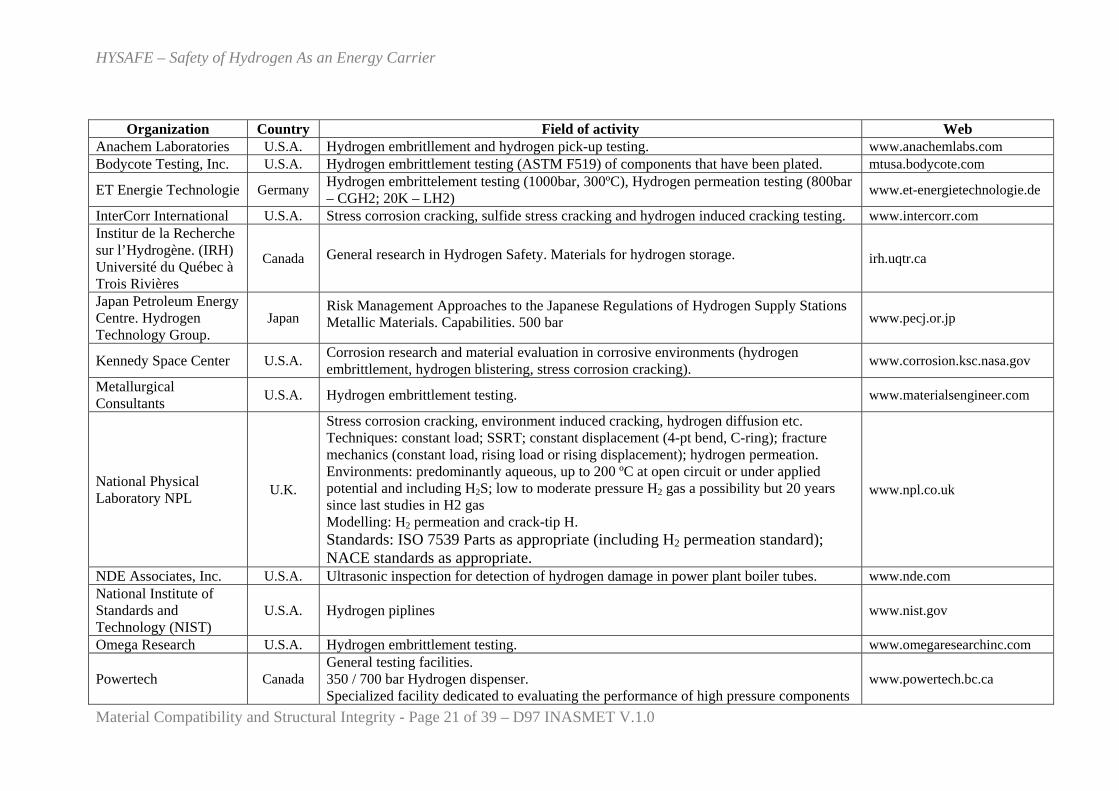
4.2 Capabilities outside the consortium
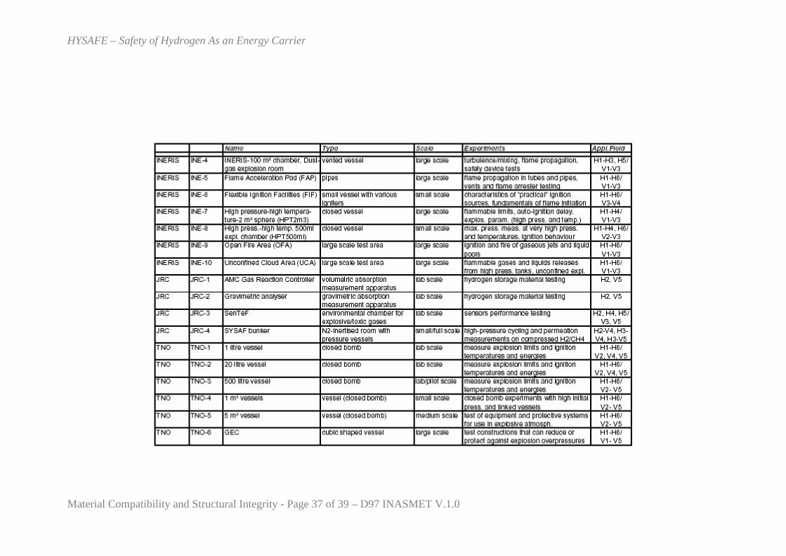
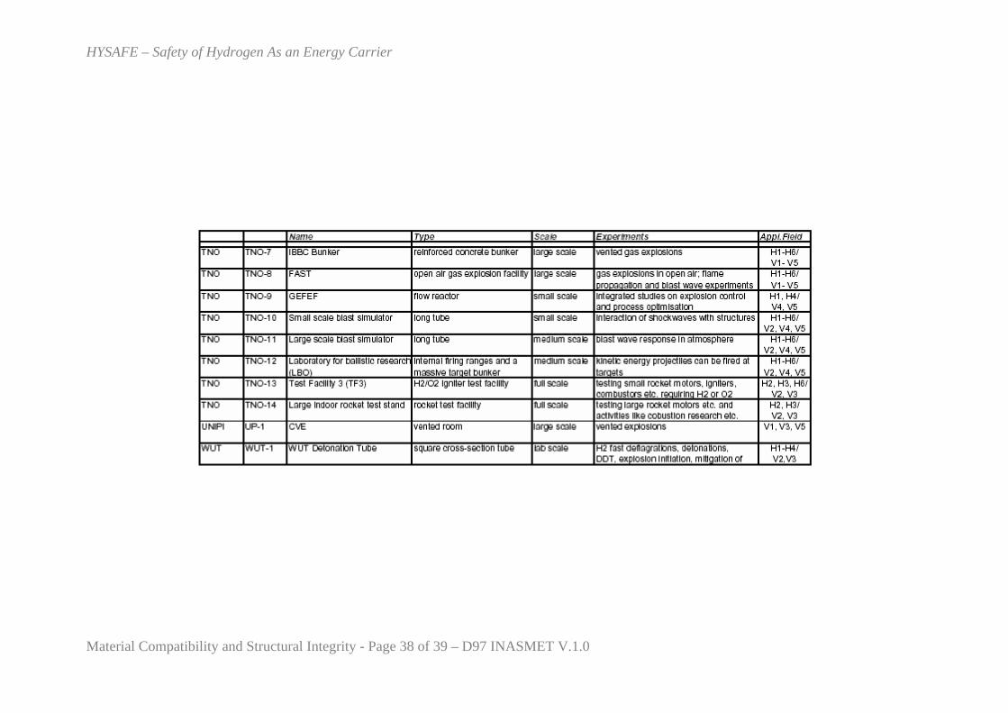
Several organizations have been identified as being appropriate for be mentioned in this deliverable due to their work in the field of study. The following table summarizes their field of activity (services for detection, evaluation etc. of hydrogen damage) and also some basic data.
HYSAFE – Safety of Hydrogen As an Energy Carrier
Material Compatibility and Structural Integrity - Page 21 of 39 – D97 INASMET V.1.0
Organization Country Field of activity Web Anachem Laboratories U.S.A. Hydrogen embritllement and hydrogen pick-up testing. www.anachemlabs.com Bodycote Testing, Inc. U.S.A. Hydrogen embrittlement testing (ASTM F519) of components that have been plated. mtusa.bodycote.com
ET Energie Technologie Germany Hydrogen embrittelement testing (1000bar, 300ºC), Hydrogen permeation testing (800bar – CGH2; 20K – LH2) www.et-energietechnologie.de
InterCorr International U.S.A. Stress corrosion cracking, sulfide stress cracking and hydrogen induced cracking testing. www.intercorr.com Institur de la Recherche sur l’Hydrogène. (IRH) Université du Québec à Trois Rivières
Canada General research in Hydrogen Safety. Materials for hydrogen storage. irh.uqtr.ca
Japan Petroleum Energy Centre. Hydrogen Technology Group.
Japan Risk Management Approaches to the Japanese Regulations of Hydrogen Supply Stations Metallic Materials. Capabilities. 500 bar www.pecj.or.jp
Kennedy Space Center U.S.A. Corrosion research and material evaluation in corrosive environments (hydrogen embrittlement, hydrogen blistering, stress corrosion cracking). www.corrosion.ksc.nasa.gov
Metallurgical Consultants U.S.A. Hydrogen embrittlement testing. www.materialsengineer.com
National Physical Laboratory NPL U.K.
Stress corrosion cracking, environment induced cracking, hydrogen diffusion etc. Techniques: constant load; SSRT; constant displacement (4-pt bend, C-ring); fracture mechanics (constant load, rising load or rising displacement); hydrogen permeation. Environments: predominantly aqueous, up to 200 ºC at open circuit or under applied potential and including H2S; low to moderate pressure H2 gas a possibility but 20 years since last studies in H2 gas Modelling: H2 permeation and crack-tip H. Standards: ISO 7539 Parts as appropriate (including H2 permeation standard); NACE standards as appropriate.
www.npl.co.uk
NDE Associates, Inc. U.S.A. Ultrasonic inspection for detection of hydrogen damage in power plant boiler tubes. www.nde.com National Institute of Standards and Technology (NIST)
U.S.A. Hydrogen piplines www.nist.gov
Omega Research U.S.A. Hydrogen embrittlement testing. www.omegaresearchinc.com
Powertech Canada General testing facilities. 350 / 700 bar Hydrogen dispenser. Specialized facility dedicated to evaluating the performance of high pressure components
www.powertech.bc.ca
HYSAFE – Safety of Hydrogen As an Energy Carrier
Material Compatibility and Structural Integrity - Page 22 of 39 – D97 INASMET V.1.0
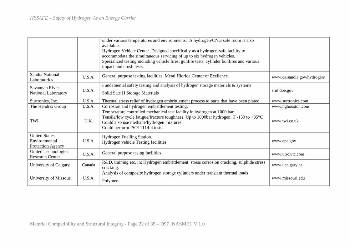
under various temperatures and environments. A hydrogen/CNG safe room is also available. Hydrogen Vehicle Center. Designed specifically as a hydrogen-safe facility to accommodate the simultaneous servicing of up to six hydrogen vehicles. Specialized testing including vehicle fires, gunfire tests, cylinder bonfires and various impact and crush tests.
Sandia National Laboratories U.S.A. General purpose testing facilities. Metal Hidride Center of Ecellence. www.ca.sandia.gov/hydrogen/
Savannah River National Laboratory U.S.A.
Fundamental safety testing and analysis of hydrogen storage materials & systems
Solid Sate H Storage Materials srnl.doe.gov
Surtronics, Inc. U.S.A. Thermal stress relief of hydrogen embrittlement process to parts that have been plated. www.surtronics.com The Hendrix Group U.S.A. Corrosion and hydrogen embrittlement testing. www.hghouston.com
TWI U.K.
Temperature controlled mechanical test facility in hydrogen at 1000 bar. Tensile/low cycle fatigue/fracture toughness. Up to 1000bar hydrogen. T -150 to +85°C Could also use methane/hydrogen mixtures. Could perform ISO11114-4 tests.
www.twi.co.uk
United States Environmental Protection Agency
U.S.A. Hydrogen Fuelling Station. Hydrogen vehicle Testing facilities www.epa.gov
United Technologies Research Center U.S.A. General purpose tesing facilities www.utrc.utc.com
University of Calgary Canada R&D, training etc. in: Hydrogen embrittlement, stress corrosion cracking, sulphide stress cracking. www.ucalgary.ca
University of Missouri U.S.A. Analysis of composite hydrogen storage cylinders under transient thermal loads
Polymers www.missouri.edu
HYSAFE – Safety of Hydrogen As an Energy Carrier
Material Compatibility and Structural Integrity - Page 23 of 39 – D97 INASMET V.1.0
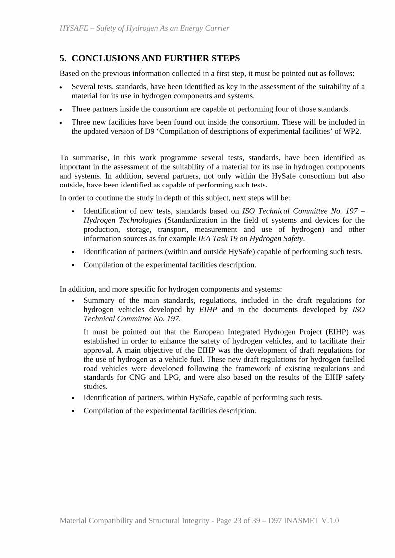
5. CONCLUSIONS AND FURTHER STEPS Based on the previous information collected in a first step, it must be pointed out as follows:
• Several tests, standards, have been identified as key in the assessment of the suitability of a material for its use in hydrogen components and systems.
• Three partners inside the consortium are capable of performing four of those standards.
• Three new facilities have been found out inside the consortium. These will be included in the updated version of D9 ‘Compilation of descriptions of experimental facilities’ of WP2.
To summarise, in this work programme several tests, standards, have been identified as important in the assessment of the suitability of a material for its use in hydrogen components and systems. In addition, several partners, not only within the HySafe consortium but also outside, have been identified as capable of performing such tests.
In order to continue the study in depth of this subject, next steps will be:
Identification of new tests, standards based on ISO Technical Committee No. 197 – Hydrogen Technologies (Standardization in the field of systems and devices for the production, storage, transport, measurement and use of hydrogen) and other information sources as for example IEA Task 19 on Hydrogen Safety.
Identification of partners (within and outside HySafe) capable of performing such tests.
Compilation of the experimental facilities description.
In addition, and more specific for hydrogen components and systems:
Summary of the main standards, regulations, included in the draft regulations for hydrogen vehicles developed by EIHP and in the documents developed by ISO Technical Committee No. 197.
It must be pointed out that the European Integrated Hydrogen Project (EIHP) was established in order to enhance the safety of hydrogen vehicles, and to facilitate their approval. A main objective of the EIHP was the development of draft regulations for the use of hydrogen as a vehicle fuel. These new draft regulations for hydrogen fuelled road vehicles were developed following the framework of existing regulations and standards for CNG and LPG, and were also based on the results of the EIHP safety studies.
Identification of partners, within HySafe, capable of performing such tests.
Compilation of the experimental facilities description.
HYSAFE – Safety of Hydrogen As an Energy Carrier
Material Compatibility and Structural Integrity - Page 24 of 39 – D97 INASMET V.1.0
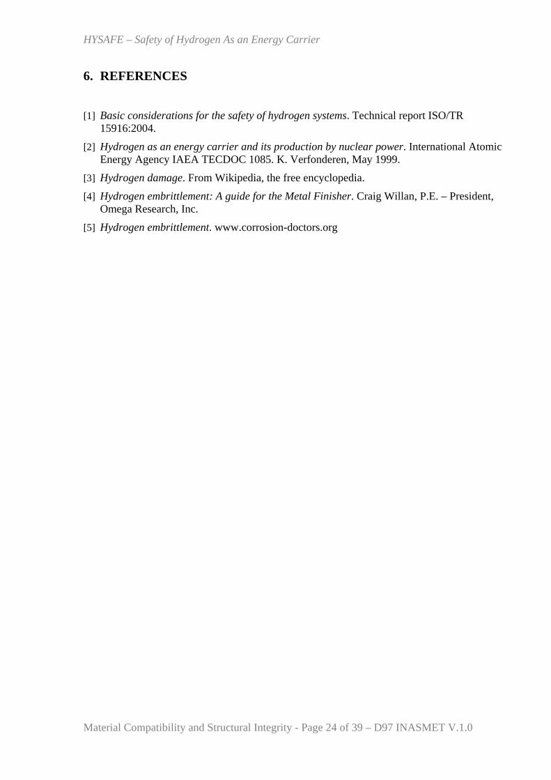
6. REFERENCES
[1] Basic considerations for the safety of hydrogen systems. Technical report ISO/TR 15916:2004.
[2] Hydrogen as an energy carrier and its production by nuclear power. International Atomic Energy Agency IAEA TECDOC 1085. K. Verfonderen, May 1999.
[3] Hydrogen damage. From Wikipedia, the free encyclopedia.
[4] Hydrogen embrittlement: A guide for the Metal Finisher. Craig Willan, P.E. – President, Omega Research, Inc.
[5] Hydrogen embrittlement. www.corrosion-doctors.org
HYSAFE – Safety of Hydrogen As an Energy Carrier
Material Compatibility and Structural Integrity - Page 25 of 39 – D97 INASMET V.1.0
Annex 1-Description of new experimental facilities (not included in WP9 – D9)
HYSAFE – Safety of Hydrogen As an Energy Carrier
Material Compatibility and Structural Integrity - Page 26 of 39 – D97 INASMET V.1.0
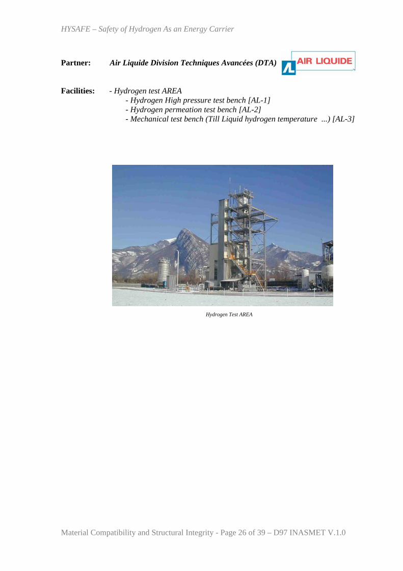
Partner: Air Liquide Division Techniques Avancées (DTA) Facilities: - Hydrogen test AREA
- Hydrogen High pressure test bench [AL-1] - Hydrogen permeation test bench [AL-2] - Mechanical test bench (Till Liquid hydrogen temperature ...) [AL-3]
Hydrogen Test AREA
HYSAFE – Safety of Hydrogen As an Energy Carrier
Material Compatibility and Structural Integrity - Page 27 of 39 – D97 INASMET V.1.0
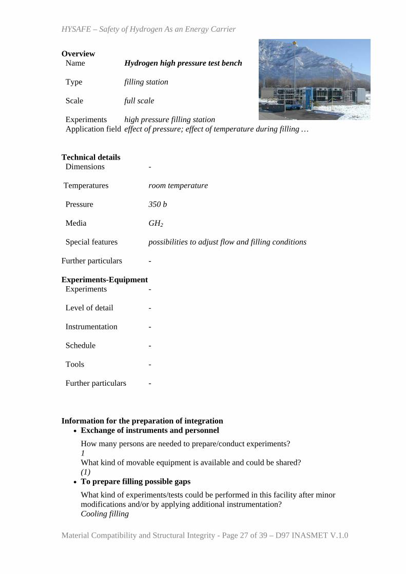
Overview Name Hydrogen high pressure test bench
Type filling station Scale full scale Experiments high pressure filling station Application field effect of pressure; effect of temperature during filling …
Technical details Dimensions - Temperatures room temperature Pressure 350 b
Media GH2 Special features possibilities to adjust flow and filling conditions Further particulars -
Experiments-Equipment Experiments - Level of detail - Instrumentation - Schedule - Tools - Further particulars - Information for the preparation of integration
• Exchange of instruments and personnel How many persons are needed to prepare/conduct experiments? 1 What kind of movable equipment is available and could be shared? (1)
• To prepare filling possible gaps What kind of experiments/tests could be performed in this facility after minor modifications and/or by applying additional instrumentation? Cooling filling

HYSAFE – Safety of Hydrogen As an Energy Carrier
Material Compatibility and Structural Integrity - Page 28 of 39 – D97 INASMET V.1.0
• To prepare promotion and specialisation What features/possibilities would you like to promote? - Which additional equipment could enhance your results? -
HYSAFE – Safety of Hydrogen As an Energy Carrier
Material Compatibility and Structural Integrity - Page 29 of 39 – D97 INASMET V.1.0
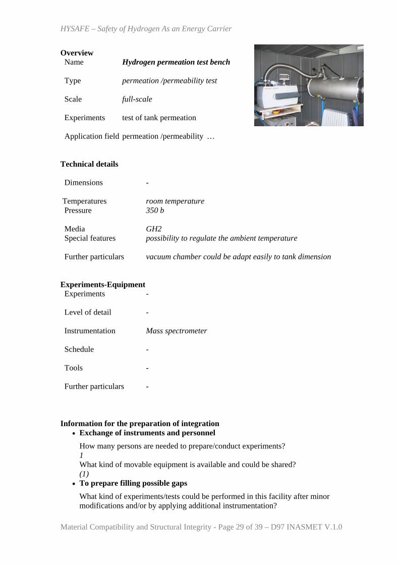
Overview Name Hydrogen permeation test bench
Type permeation /permeability test Scale full-scale Experiments test of tank permeation Application field permeation /permeability …
Technical details Dimensions -
Temperatures room temperature Pressure 350 b
Media GH2 Special features possibility to regulate the ambient temperature
Further particulars vacuum chamber could be adapt easily to tank dimension
Experiments-Equipment Experiments - Level of detail - Instrumentation Mass spectrometer Schedule - Tools - Further particulars - Information for the preparation of integration
• Exchange of instruments and personnel How many persons are needed to prepare/conduct experiments? 1 What kind of movable equipment is available and could be shared? (1)
• To prepare filling possible gaps What kind of experiments/tests could be performed in this facility after minor modifications and/or by applying additional instrumentation?

HYSAFE – Safety of Hydrogen As an Energy Carrier
Material Compatibility and Structural Integrity - Page 30 of 39 – D97 INASMET V.1.0
Adjustable environment temperature • To prepare promotion and specialisation
What features/possibilities would you like to promote? - Which additional equipment could enhance your results? -
HYSAFE – Safety of Hydrogen As an Energy Carrier
Material Compatibility and Structural Integrity - Page 31 of 39 – D97 INASMET V.1.0
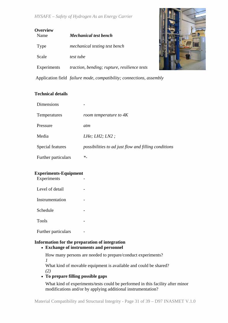
Overview Name Mechanical test bench
Type mechanical testing test bench Scale test tube Experiments traction, bending; rupture, resilience tests Application field failure mode, compatibility; connections, assembly Technical details Dimensions - Temperatures room temperature to 4K Pressure atm
Media LHe; LH2; LN2 ; Special features possibilities to ad just flow and filling conditions
Further particulars *-
Experiments-Equipment Experiments - Level of detail - Instrumentation - Schedule - Tools - Further particulars - Information for the preparation of integration
• Exchange of instruments and personnel How many persons are needed to prepare/conduct experiments? 1 What kind of movable equipment is available and could be shared? (2)
• To prepare filling possible gaps What kind of experiments/tests could be performed in this facility after minor modifications and/or by applying additional instrumentation?
HYSAFE – Safety of Hydrogen As an Energy Carrier
Material Compatibility and Structural Integrity - Page 32 of 39 – D97 INASMET V.1.0
Poisson ratio measurement at LH2 temperature • To prepare promotion and specialisation
What features/possibilities would you like to promote? - Which additional equipment could enhance your results? -
HYSAFE – Safety of Hydrogen As an Energy Carrier
Material Compatibility and Structural Integrity - Page 33 of 39 – D97 INASMET V.1.0
Annex 2-References of experimental facilities (WP2 –D9)
HYSAFE – Safety of Hydrogen As an Energy Carrier
Material Compatibility and Structural Integrity - Page 34 of 39 – D97 INASMET V.1.0
HYSAFE – Safety of Hydrogen As an Energy Carrier
Material Compatibility and Structural Integrity - Page 35 of 39 – D97 INASMET V.1.0
HYSAFE – Safety of Hydrogen As an Energy Carrier
Material Compatibility and Structural Integrity - Page 36 of 39 – D97 INASMET V.1.0
HYSAFE – Safety of Hydrogen As an Energy Carrier
Material Compatibility and Structural Integrity - Page 37 of 39 – D97 INASMET V.1.0
HYSAFE – Safety of Hydrogen As an Energy Carrier
Material Compatibility and Structural Integrity - Page 38 of 39 – D97 INASMET V.1.0

HYSAFE – Safety of Hydrogen As an Energy Carrier
Material Compatibility and Structural Integrity - Page 39 of 39 – D97 INASMET V.1.0