sixth fast js series gearbox - china truck parts · 2018-11-03 · figure 6-13 the gear shift...
TRANSCRIPT

.
Sixth fast JS series gearboxAs described above, is RT11509C type transmission Fusite introduction of basic type gearbox in the United States Fuller (Fu11er) gearbox. At the same time, also the introduction of part variant, for example RT11609A is design of fine tooth design (RT11509C is coarse teeth), RTO11609B with overdrive design and so on. These variants of the basic structure, working principle of dis assembly procedures and RT11509C type identical.In recent years, Shanxi Fast Gear Co., Ltd. according to the design concept of double counter shaft, adapt to the market demand, a 7ds, 7JS, 8JS, 9JS, 12JS and 16JS etc. a series of twin counter shaft transmission. In addition to 7ds series is only Main box without side box of single box structure, the rest of the series gearbox is the main, vice box with a twin counter shaft transmission. Figure 6-1 is 7ds series gearbox structure diagram figure 6-2 is the transmission route map.
Figure 7DS 6-1 series gearbox structureFigure 6-3 is the 7JS and 8JS series gearbox main box structure diagram 6-4 is the 7JS series transmission route map 6-5

Figure 7DS 6-1 series gearbox structureFigure 6-3 is the 7JS and 8JS series gearbox main box structure diagram 6-4 is the 7JS series transmission route map 6-5 Is the transmission path 8JS series gearbox.In recent years, Shanxi Fast Gear Co., Ltd. according to the design concept of double counter shaft, adapt to the market demand, a 7ds, 7JS, 8JS, 9JS, 12JS and 16JS etc. a series of twin counter shaft transmission. In addition to 7ds series is only Main box without side box of single box structure, the rest of the series gearbox is the main, vice box with a twin counter shaft transmission. Figure 6-1 is 7ds series gearbox structure diagram figure 6-2 is the transmission route map.From the above structure diagram and transmission line drawings can be seen: 7ds series gearbox is only a twin counter shaft gearbox without auxiliary gearbox single gearbox. And 7JS and 8JS series gearbox of the basic structure of the same, different is 7JS gearbox in high speed range, from the control system removed a file, as shown in Figure 6-4 and 6-5. In terms of the 8JS series gearbox: when Vice box hanging low gear and a, the second gear synchronizer backward with the first gear with and gearbox linked to a file; pushed forward into the combined with the second gear wheel, gearbox linked gear; third, fourth gear synchronous Back with the third gear combination, hanging gear gearbox, pushed forward into the combined with a shaft gear, gearbox hang into the direct file 4 file. When the gearbox auxiliary box high gear, main box repeat the gear process is formed five, six, seven, eight stalls. As shown in Figure 6-4, we can see: when 7JS series gearbox hanging low gear,One, two, three,, four,, the gear box is the same as the 8JS gearbox,When the auxiliary gearbox high gear, the main gear box, gear synchronizer is directly pushed forward into the engagement with the gear form
5 files; third, fourth gear synchronizer backward and third gear combination, forming a 6-speed; three or four gear synchronizer pushed forward into the and a shaft gear combined to form the 7th gear. Obviously, 7JS gearbox is in highgear area will be a, gear synchronizer backward with the first gear with the operation, operation device from removed. This is the difference between the gearbox with 8JS. In other words: 7JS gearbox is in 8JS gearbox based removed a gear andthe formation of, this is the only.From figure 6-4 and 6-5 we can see the gear box with the direct file (7JS100,8JS100,8JS100T, 8JS115T, 8JS118,
8JS118T (8JS130,8JS180,) and a gearbox (7JS100A, 8JS100A, 8JS100TA, 8JS115TA,),
8JS118A, 8JS118TA, 8JS130A, 8JS180A) difference between only in different ratios, and the power transmission line is slightly different. From the diagram of transmission line can be seen: with direct shift gearbox, vice box hanging low gear,

three, four gear synchronizer dial in combination with the third gear, gearbox present gear; push combined with a shaft gear, gearbox showing fourth gear. When the auxiliary gearbox high gear, three, four gear synchronizer same dial into third gear with, the gearbox has seven gears; push
Figure 7DS 6-2 series transmission route map
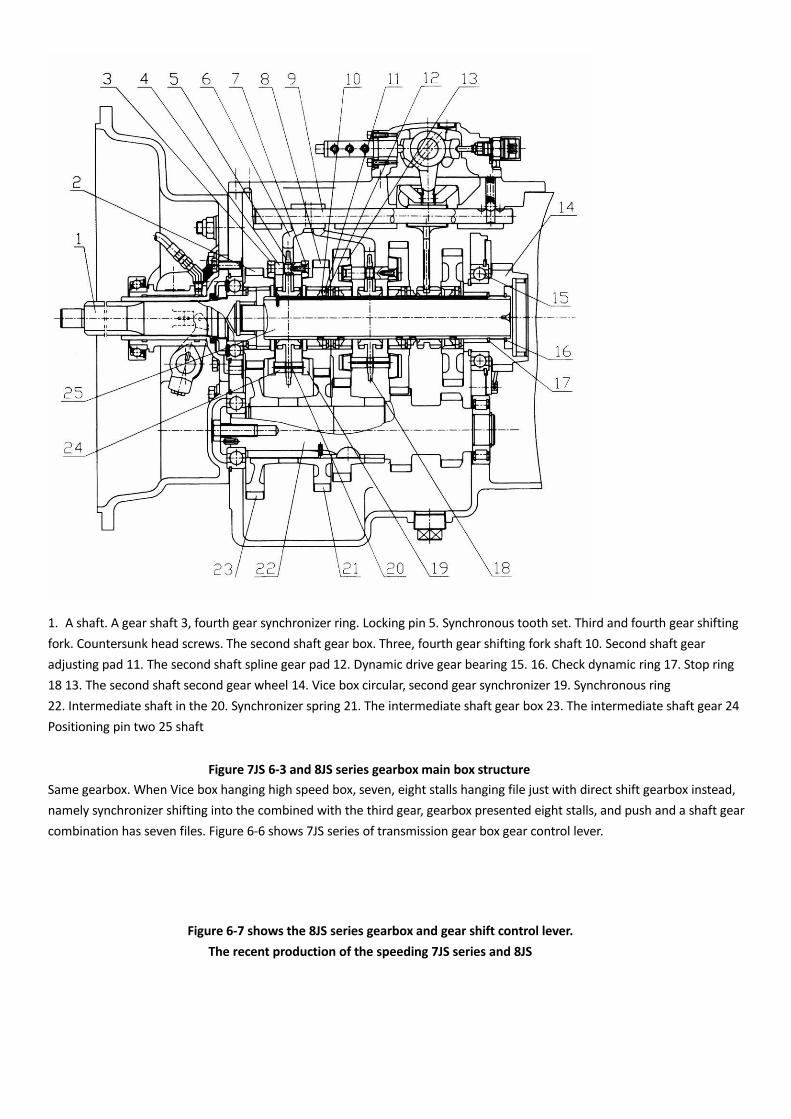
1. A shaft. A gear shaft 3, fourth gear synchronizer ring. Locking pin 5. Synchronous tooth set. Third and fourth gear shifting fork. Countersunk head screws. The second shaft gear box. Three, fourth gear shifting fork shaft 10. Second shaft gear adjusting pad 11. The second shaft spline gear pad 12. Dynamic drive gear bearing 15. 16. Check dynamic ring 17. Stop ring 18 13. The second shaft second gear wheel 14. Vice box circular, second gear synchronizer 19. Synchronous ring22. Intermediate shaft in the 20. Synchronizer spring 21. The intermediate shaft gear box 23. The intermediate shaft gear 24 Positioning pin two 25 shaft
Figure 7JS 6-3 and 8JS series gearbox main box structureSame gearbox. When Vice box hanging high speed box, seven, eight stalls hanging file just with direct shift gearbox instead, namely synchronizer shifting into the combined with the third gear, gearbox presented eight stalls, and push and a shaft gear combination has seven files. Figure 6-6 shows 7JS series of transmission gear box gear control lever.
Figure 6-7 shows the 8JS series gearbox and gear shift control lever.The recent production of the speeding 7JS series and 8JS

Same gearbox. When Vice box hanging high speed box, seven, eight stalls hanging file just with direct shift gearbox instead, namely synchronizer shifting into the combined with the third gear, gearbox presented eight stalls, and push and a shaft gear combination has seven files. Figure 6-6 shows .7JS series of transmission gear box gear control lever.Figure 8JS shows the 6-7 series gearbox and gear control lever gear box. The recent production of the speeding 7JS series and 8JS series gearbox, for the convenience of the operator to operate, the steering gear and the direct file is the same. 7JS series and 8JS series of direct or speeding gear box, are loaded with remote control of dual H shift mechanism.H shift mechanism ", as shown in Figure 2-11, which is the transmission shaft 6 is responsible for a shift lever 5 and toggle double H shift.Shifting block to hang together of a gear, and lateral movement control double h shift valve decision boxes are high and low. The shift of the main box and an auxiliary box shift two tasks by a shifting shaft at the same time to complete. This kind of shift gas such as shown in Figure 2-13.

In the RT11509C basic type gearbox based, to enhance the product of the output torque is 9JS series gearbox. The structure and RT11509C type is basically the same, it also has 9 forward gears and one reverse Lord, vice box twin countershaft transmission. Figure 6-8 is structure chart without synchronizer 9JS series gearbox, figure 6-9 is the transmission route map.Figure 6-9 although the 9JS180 and 9JS180A type of transmission is given the power transmission line, in fact, 9JS full range of transmission lines are the same.
Figure 7JS 6-4 series transmission route map
Figure 8JS 6-5 series transmission route map
Type 7JS100 (direct file type) 7JS100A type (over speed type)

Figure 7JS 6-6 series of gear box bitmap
7JS100;8JS100T 8JS100A;8JS100TA
8JS115T;8JS118 8JS115TA;8JS118A
8JS118T;8JS130 8JS118TA;8JS130A
8JS180 (direct file type) 8JS180A ( over speed file type)
Figure 8JS 6-7 series of gear box bitmap
Figure 9JS 6-8 non synchronous series gearbox structure schematic diagram

Figure 9JS 6-9 series transmission route map
The shift control mechanism of 9JS series gearbox has "single pole double H remote control shift mechanism"; "double pole double H remote control shift mechanism" and "air valve direct control single H shift mechanism" three kinds.
So-called "single pole double h remote control shift mechanism" is as described above: control of the main gear box gear changes and is changed into an auxiliary gearbox double h shift valve are is by a shifting shaft to complete, the structure shown in Figure 2-10 RT (RTO) series and 7JS; 8JS series gearbox basic on the gearshift mechanism of this shift shaft the so-called "double pole double h remote control shift mechanism of action is respectively by two sets of lever or flexible shaft to control.

Figure 6-10 is the structure of this shift mechanism, as shown in Figure 6-10, this "double pole double H" shift mechanism with "single pole double H for The gear mechanism is different: the shift mechanism adds a selector lever 4. This gearbox external a shift lever through shifting turn arm 10 only control the shifting shaft 6 of the rotation, and the shifting rod and the backs wing is to achieve the main gearbox picking and hanging files. And the other a lever (or soft), through the selector shaft 22 control selector lever 4 left and right moving the shift lever 15, so as to determine the shift gear.Obviously auxiliary gear box high and low transformation, but also by the lever (or soft) by moving the shift lever 15 the left and right position manipulation double h shift valve 16. Obviously, gearbox Two control levers have a certain linkage, the linkage mechanism in the external gearbox.
1.3. balance spring 2 positioning ring 4 selector lever 5 key 6 shift shaft 7 reverse indicator 8 neutral indicator light 9 baffle.The 10 shift arm 11 shift joint 12 spline sleeve 13 ventilation plug 14 reverse switch control block 15 gearshift lever 16 double H 17 valve, dual H control unit housing 18 positioning plunger 19 compression spring 20 21 side window cover 22 selector
Axis figure 6-10 double pole double H remote control shift mechanism
Figure 6-11 shows the "single shot" or "double pole double h shift mechanism of pneumatic circuit diagram. The double h shift valve and shift cylinder (including engineering vehicle with band gap shift cylinder) structure and RT11509C gear box" a section describes exactly the same. Shown in Figure 6-12 9JS variable speed box used (single rod and double rod) double h shift control handle file bitmap. From the figure can also be seen direct file (9JS119; 9JS119T; 9js135; 9JS135T; 9JS150; 9JS150T; model 9js180; 9JS2 20; 9JS180T; 9JS220T; 9JS240T; 9JSS180; 9JSS220; 9JSS260 and other gear box with the speed file type (9JS119A, 9JS135A, 9JS180A, 9JS220A, 9JS180TA, 9JS200TA,, 9JS240TA, etc.)

Figure 6-12 9JS series gearbox double h shift control handle file bitmap speed gear, the only difference is high-speed seven, eight stalls of different positions. The recent production of 9JS series of the overdrive gearbox, for then driving personnel operation habit, on 7 / 8 overdrive files added a reversing mechanism, the overdrive gearbox of joystick stalls and direct gear gear exactly the same.
"9JS series variable column gear box and a kind of insert file type valve controlled single h shift mechanism. Such as in Figure 6-13 the gear shift mechanism in the shift lever handle installed on a pres elector valve, the air valve to control a two bit three-way reversing valve shift rod to directly control a single shift shifting block, which decided the main gearbox gear side gearbox of high-low pres elected by a valve through the reversing valve to control. Specifically: when pres elector valve switch dial to" low "position, transmission shift lever can be realized, second, third, fourth gear. When the primary switch dial to" high speed "position, shift lever in the same position five and six. Seven, eight speed gearbox. Also has a "direct drive" and "overdrive" seventh, eight stalls stalls just the opposite.
Figure 6-14 shows the valve direct control of single h shift mechanism of the bitmap file. On the basis of 9JS series gearbox, in the main box to increase a gear drive gear, it becomes 12 gear box, which is 12JS series of gearbox.

Figure 6-13 single H control valve shifting mechanism of gas path
Figure 6-13 single H control
valve shifting mechanism of gas path
A single H gear shift mechanism for over speed shift
Figure 6-14 air valve control single H gear shift mechanism
Figure 6-15,12JS is composed of a series of gearbox with six forward gears and a reverse gear of the main gear box and a high,Low two tranches of the auxiliary gearbox combination with 12 speeds forward and two reverse gearbox. Lord, auxiliary gearbox is of course a twin counter shaft structure.12JS series gearbox to all synchromesh gearbox, the main box with double cone inertia synchronizer, vice box uses a strengthen type lock pin synchronizer, good synchronization performance shift light good hand feel.

12JS series gearbox using remote control single shift mechanism. Figure 6-16 gives a single shift mechanism, figure 6-17
The single shift mechanism are also given in Figure 6-15 gas diagram, single gear shifting mechanism of the bitmap.
Through operating, is the so-called "single" gearshift gear shift mechanism with three rows of shifting block. As shown in Figure 6-16, gear box control rod through a series of connecting rod crank arm 19, the shifting shaft before and after 8 swings and left and right lateral movement, the shift of the axial and lateral movement can choose stalls, and swing the gearshift lever 14 toggle shifting block gear and pick up the block. Due to a shift of the agencies in addition to the reverse gear shifting block side by side with three rows of shifting block, which is 1-2 files (7-8) shifting block; 3-4 gear (9-10) shifting block and 5-6 file (11-12 file) shifting block. So called single Gear shift mechanism.
Figure 12JS 6-15 series gearbox structure

Figure 12JS 6-15-1 series transmission route map

1 low down switch control block 2 air pipe assembly 3.90 degrees quick change joint three 4 way pipe joint 5 gas path control valve 6 cylinder Shaw 7 spring seat 8 change Gear shaft. The side limit of 10. A set of 11. A compression spring 12. Control device casing 13. Shifting shaft bushing 14. Shift dial rod 15. Ventilation plug 16. Oil 17.18 sets of elastic cylindrical Shaw 19 shift crank arm 20 reverse switch 21 neutral switch
Figure 6-16 single H gear shift mechanism structure
1 air filter regulator 2 main pipe 3 transition pipe 4 air inlet pipe 5 shift handle control .6 control of the 9 high grade 7 of the pipe line 8 gas control valve 10 gas path control valve
Figure 6-17 single shift gas diagram
This shift gearbox procedure is: as figure 6-17 car before starting the first will shift handle 5 primary valve switch is pulled downward to the low-grade area, when the gearbox in neutral position, gas path control valve 9 is opened, to compress the air way reversing valve 10, and shifting cylinder low speed air inlet joint, gear shifting cylinder of the auxiliary gearbox hanging low gear. Thereafter, with the normal running of the automobile, gearbox shift rod by way of hanging 1-2-3-4-5-6 file. If you want to from 6th gear change gear, the clutch pedal is stepped on,

Push and accelerate the return will be the first lever from 6 stall picking gap, then, will handle the primary switch to dial to "high-grade", this time pres election switch will shift valve 10 commutation, so that the gear shifting cylinder of high gear joint to annoy, low profile connector gas, shift cylinder side gearbox change into high-grade, and finally the transmission lever is pushed into the seventh gear position. Since then, along with the automobile, only manipulation of the shift lever can be realized 7-8-9-10-11-12 transform double h shift mechanism similar to single shift mechanism in sixth gear change into seven files or by seven speed sixth gear, gear shifting operation should not be too quick and coherent, i.e. from six files back into neutral. First pres elector valve switch is allocated to the high position, pause, deputy box are cheap to be change into after the upscale, then the shift operating lever is pushed into seven files. From seven speed change gear, also have certain interval so as to avoid, auxiliary gearbox shift at the same time, clutch if vice box gear fault due to combined too quickly.Specifically: the single shift mechanism, although the pres election switch to replace vice box of high and low, but gearbox is still range gear gearbox. That is to say it must be in accordance with 1-2-3-4-5-6-7-8-9-10-11-12 such a sequence of by gear up shift and downshift, not like inserting a gear box as from a file is changed directly into seven files and so on.Special attention is paid to: single shift mechanism in the gas path control valve 9 (Figure 6-17) and double H shift mechanism in the dual H shift Valve although the installation position is the same, but the role of the valve is fundamentally different. Double h shift valve is a two position four-way valve, which directly control the gear changing cylinder to achieve high side box, low-grade shift. And single shift gas path control valve 9 is a two position two-way valve, its role is only the main box in the neutral position, compressed air through the valve to air way reversing valve 10, and realizes the high side box, low-grade shift. Therefore, it is a protection device.Another is different from the double h shift mechanism is: the air filtration of single shift mechanism adjustable voltage regulator 1 (Figure 6-17), the source of 0.7 ~ 0.8MPa (MPA) pressure filter adjustment for 0.57 ~ 0.6 (MPA) pressure to shift gas path.12JS series gearbox auxiliary box shift cylinder structure and the model exactly the same. In order to improve the performance of the vehicle starting and improve the maneuverability, Fast gear Co Ltd and have developed a 16JS series gearbox.Compared with a two and the formation of a series 8JS in series as shown in Figure 18 and figure 6-19,16JS gear box gear box structure, and the front half gear mechanism. The so-called pre semi gear mechanism is the main gear box input shaftis arranged two driving gear shaft driven gear, the formation of two sets of different ratio of main and passive transmission. In one axis and two active intermediate gear syn chronizer gear mechanism syn chronizer gear sleeve with different active gear, and the formation of the different ratio, so that the original gearbox gear extends the times, because the input shaft and the auxiliary shaft two sets of the main, passive gear ratio range Small and, therefore, to change gears, front stalls transform can in any gear. Exactly speaking, 16JS series gearbox is by a has four front into gear and a reverse gear of the main gearbox and a high, low profile of an auxiliary gearbox and a is composed of half and half low gear of front side box with 16 forward gears and two reverse insert type gearbox. The main gearbox, the pre positive semi gear boxes and therear auxiliary box is double shaft structure.Through a series as shown in figure 6-18,16JS speed change box input shaft is arranged on the two driving gear, a high axial half shift driving gear 4 and half low gear driving gear 2, corresponding to the two counter shaft counter shaft and a half high gear driven gear and low half shift driven gear 14. In one axis and two driving gear is arranged between a and a spline shaft linkage synchronizer 23, so formed a with high and low half file pre vice box. The so-called "half", is refers to the two speed differential is small. Front auxiliary gearbox shift speed changing handle 12 pres elected switch 22 control front auxiliary gear shifting cylinder 3. In addition to the outside. Differential series series due to the fully variable 8JS other structure and speed box the same. 16JS variable speed box file and therefore the stall speed ratio range is small (only 1.21%), so that the work of two adjacent stall speed difference is small, so the shift light freely, synchronizer relative load is smaller, the synchronizer life will be more long. At the same time, start gear ratio can do more, (first gear ratio as high as 17.04), improve the car started the slope climbing ability, start more stable.16JS gear box fine tooth design, together with the adjacent stall speed ratio is small, because the "tooth" assembly special Whether in in order to move a "tag to the attention of the assembly must be carefully" on the tooth, and strictly according to the tooth marks on assembly. If not carefully details are easy to mistake. Sometimes the teeth are not accurate, occasionally also can be assembled, and the assembly and the shaft can rotate a few laps, but such a gearbox mounted to the vehicle, as long as the engine is driven to rotate, it will cause serious damage. In the main assembly box counter shaft, if the intermediate shaft to spend a lot of

effort plate alignment bearing inner hole, means "tooth" is installed, carefully check. The gearbox assembly is completed, be sure to check the running freely.
1,Input shaft 2, a shaft half file active gear 3 front auxiliary gear shifting cylinder 4. A shaft to the entire file active gear. Double h shift valve 6. Double h for constitutive mechanism 7. Shifting shaft. The neutral switch. Output shaft. The main box output gear 11. Vice box shift cylinder gear shifting handle 13. Counter shaft (intermediate shaft) 14. Semi minor axis gear driven gear 15. Counter shaft the entire file passive gear 16. The main box second shaft gear box 17. The main box second shaft second gear 18. Box main shaft first gear 19. The second shaft reverse gear 20. Vice box output shaft 21 22. The auxiliary box counter shaft half shift switch 23 is a selected sequence of half shaft gear synchronizer
Figure 16JS 6-18 series gearbox structure
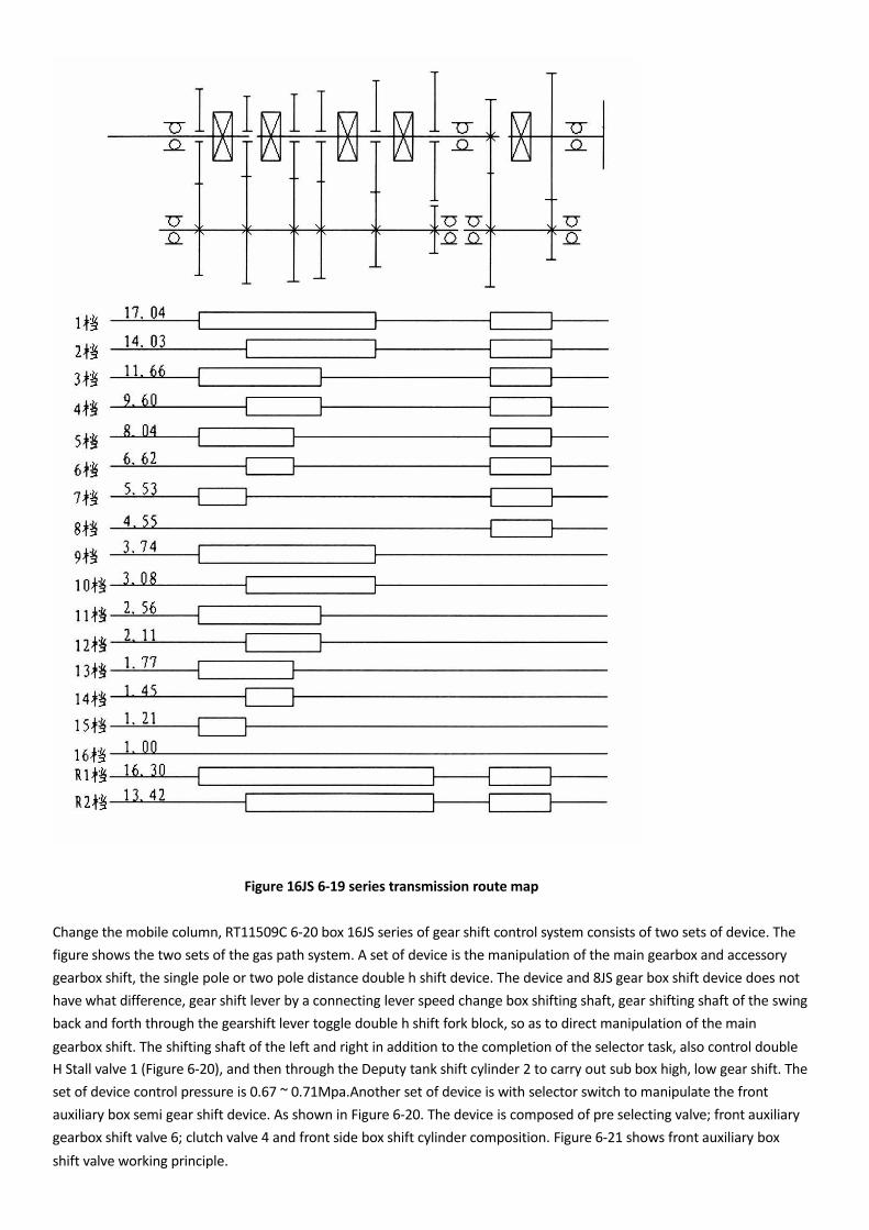
Figure 16JS 6-19 series transmission route map
Change the mobile column, RT11509C 6-20 box 16JS series of gear shift control system consists of two sets of device. The figure shows the two sets of the gas path system. A set of device is the manipulation of the main gearbox and accessory gearbox shift, the single pole or two pole distance double h shift device. The device and 8JS gear box shift device does not have what difference, gear shift lever by a connecting lever speed change box shifting shaft, gear shifting shaft of the swing back and forth through the gearshift lever toggle double h shift fork block, so as to direct manipulation of the maingearbox shift. The shifting shaft of the left and right in addition to the completion of the selector task, also control doubleH Stall valve 1 (Figure 6-20), and then through the Deputy tank shift cylinder 2 to carry out sub box high, low gear shift. The set of device control pressure is 0.67 ~ 0.71Mpa.Another set of device is with selector switch to manipulate the front auxiliary box semi gear shift device. As shown in Figure 6-20. The device is composed of pre selecting valve; front auxiliary gearbox shift valve 6; clutch valve 4 and front side box shift cylinder composition. Figure 6-21 shows front auxiliary boxshift valve working principle.

Air filtering pressure regulating valve to control pressure, decompression to 0.28 ~ 0.32Mpa (MPA) and the clutch switch valve 4 through to the front side box shift valve. The shift valve 6 by manipulating handle given selection valve control, shift valve 6 two output lines connected to front auxiliary gearbox shift cylinder.
1 double H shift valve 2 side gear shifting cylinder 3 air filtration pressure regulating valve 4, clutch switch.5, clutch pedal 6 front sub box shift valve
Figure 6-20 16JS series transmission control system of gas path
Hang 8 4 5 when the driver depresses the clutch pedal, the clutch switch valve open, compressed air to the shift valve 6. At the same time, through the shift valve 6 and then leads to the pre selecting valve. If at the moment, given the selected valve switch to dial to the so-called "even gear position, pre selecting valve closed, as shown in Figure 6-21, change file spool is compressed air push right to figure 6-21 (b) of the position, then the compressed air through the shift valve tohigh-grade trachea 3 to promote pre shift cylinder piston moves to the right, so as to make a synchronous shaft is engaged with a shaft half high gear, automobile in semi high speed variable speed driving, if in step on the clutch pedal. Pre selecting and switch is pulled downward to the so-called "the odd gears" position, as shown in Figure 6-21, pre selecting valve open, compressed air through the trachea p 2 leads to the shift valve "P" joint, as shown in Figure 6-21 (c), due to the role of differential pressure, shift the spool to the left was pushed to the limit position. Then spool compressed air leads to low pipe 4, and high-grade trachea 3 compressed air by shifting the emptying valve. Shift cylinder 8 piston forward (left) is introduced and a synchronous shaft is combined with a low axial semi gear, gearbox will half low gear speed changing range in driving.Clutch switch valve of the role is to ensure that in the clutch pedal is trampled under the complete separation of the clutch, shift front side box can be achieved, to avoid driving personnel mis operation, gearbox under full load shift bit damage caused by fault.Figure 16JS gives the 6-22 series of transmission gear box with the handle of the file bitmap.By fig 6-22 to me: when the pre selecting valve switch to dial to "1" position, gearbox will appear in the"2-4-6-8-10-12-14-16" even gear range, when pre selecting valve switch is pulled downward to "2" location, gearbox will present "1-3-5-7-9-11-13-15" the odd gears range. Under normal circumstances, the car is running or in even gear range or

run.In the odd gears range while driving personnel according to the load change, in any gear, can manipulate given selection valve switch, which is from the odd gears for even gear or is from even gear for the odd gears. In other words, odd and even gear in any gear position can be put in transformation. Therefore, 16JS series gearbox main box and rear auxiliary box is a range of gear box design, and front side box is a insert gear box design.

7 4〈α〉
8
( b )
L。w •g r: , d o 仰: ,
cho :1
( c )

1 to choose the valve 2.P 3 high grade trachea 4, 5 air intake pipe。6.S gas pipe 7 pre Deputy box shift valve 8 front sub box shift cylinder figure 6-21 front gear box shift valve working principle
Figure 16JS 6-22 series of variable speed gear shift
Please note: 16JS series gearbox in the main box and rear sub box double H gear shift, the clutch must be completely separate, otherwise the synchronization will cause early wear, which is common sense.In front side box of pre selecting valve control shift, even more so, if in the shift, clutch pedal in the end, from the separator is not complete will not only cause the incipient fault of the synchronizer, and because there is no clutch switch valve connected, and the shift can not be achieved. Obviously, if front auxiliary box cannot shift occurs, it should be first examined pre selecting valve, shift valve, especially clutch switchvalve.Highway vehicle 16JS series gearbox rear auxiliary box shifting cylinder and the other twin counter shaft gear box does not have what difference, for engineering vehicle 16JS series gearbox in the rear auxiliary box shifting cylinder and general gearbox different, in order to ensure the gap, the addition of two intermediate piston position 13 and 10, as shown in figure 6-23.Nine gear speed changing box for in order to improve the output power of the gear box, the greater extent to reduce noise, Fast Gear Co., Ltd. and the development of a three shaft gearbox, the introduction 9JSS180,9JSS220 and 9JSS260 etc.. After the series gearbox set side box by 120 DEG symmetrically arranged three vice shaft structure and the auxiliary gearbox structure is more compact, more stable transmission.Believe that this counters haft and multiple counter shaft gearbox variant will applied to other gear series gearbox.Recently, fast and the development of a suitable for truck, special vehicle, truck crane, especially suitable for large passenger cars, luxury bus 8 speed gear box models were 8JS105T (a), and 8JS125T (a) and8JS160T (a). It uses full syn chronizer design, the main box adopts double cone inertial lock pin synchronizer, vice box with novel inertial lock pin syn chronizer. The steering mechanism adopts the control air valvesingle h shift mechanism.Fusite twin counter shaft transmission according to the type of shift mechanism is divided into two categories: one is engagement full set of shift mechanism, another is full synchronizer structure.Engagement full set of shift Fast gear box main box using a meshing sleeve gear. Because the auxiliary gearbox is double h valve gas transmission control. Therefore, the full range of Fast gear box side box are used inertial lock pin synchronizer, as shown in Figure 6 to 24 (c).In the full synchronizer shift gearbox, the main gearbox, reverse gear meshing sleeve by gear, 7JS-T, 8JS-T and 9JS-T Synchronizer gear box series synchronizer using conventional single inertial synchronizer as shown in Figure 6-24 (a).12JS-T series

1. Scope of shift fork axis. Scope gear cylinder cover shell 4.0 circle. Hexagon nylon locking nuts. Ventilation plug. The middle position cylinder 8. Axial ring 9. The cylinder cover 10. The middle point of the cylinder piston 11.O type ring 12. Hollow shaft 13. Middle position cylinder piston bolt 14 .Bolt 15. Range profile cylinder piston
Shift cylinder structure figure 6-23 16JS series gearbox with neutral
Fig. schematic diagram of the type of 6-24
The gearbox, the side box adopts the reinforcing ring type synchronizer main box adopts double cone synchronizer inertia, as shown in Figure 6-24.(b).16JS-T series gearbox main box installed with double cone inertia synchronizer, as shown in Figure 24 (b), the front side box fitted with single cone inertia lock ring type synchronizer as shown in Figure 24 (a), the rear auxiliary box installed with enhanced type synchronizer.As figure 6-25 double cone inertia synchronizer and conventional lock ring synchronizer only difference is between the synchronizing cone and the synchronized taper ring installation of a double cone cone ring. The synchronizer in the synchronization process, surface friction increased one times, due to the synchronization effect is enhanced by the times, makes the shift operation more smoothly.

1 tooth ring 2 tooth ring 3 spring 4 tooth seat 5 outer cone ring 6 double cone ring 7 cone 8 inner cone ring
Figure 6-25 double cone inertial synchronizer structure
To tie in with the work of the different specifications of the clutch, JS series gearbox of a shaft specifications also has two: equipped with Phi 420 mm spiral spring clutch and phi 430 mm push type diaphragm spring clutch gearbox shaft spline specifications for SAE10C1. (SAE standard 10 toothed C spline type, diameter 1 inch that phi 44.45 mm); equipped with Phi 430 mm pull type diaphragm spring clutch gearbox shaft spline specifications for SAE10C2 (10 teeth type C standard SAE spline, by 2 inches 50.80 mm). In the maintenance required replacement parts should be noted.