sitemanager™ xx29, xx39 and xx49 working with i/o ports
TRANSCRIPT

Page 1 of 13
This document describes how to operate the I/O ports of the SiteManager.
This document is supplementary to the “SiteManager Initial Contact” leaflets and the SiteManager product data sheets. These publications can be found on the Secomea web site.
This guide is applicable to SiteManager firmware version 5.9 (15123) or newer.
Version 3.1, March 20, 2015
SiteManager™ xx29, xx39 and xx49 Working with I/O Ports

SiteManager xx29, xx39 and xx49 - Working with I/O ports Page 2 of 13
Table of Contents
Introduction 3
1. About GND, 0V GND and Shield 3
2. Digital Input Ports (ALL SiteManager models) 4
2.1. Electrical information 4
2.2. Digital Input ports default functionality 4
2.3. Low-side Output switching equipment example 4
2.4. High-side Output switching equipment example 5
2.5. Changing Input 1 default functionality 5 2.6. Defining Input port Alerts 6
3. Digital Output Ports 7
3.1. Digital Output ports - Electrical information 7
3.2. Low-side Input switching equipment example. 8
3.3. High-side Input switching equipment example. 9
4. Relay Output Port (isolated) 10
4.1. Relay output ports - Electrical information 10
4.2. Low-side Input switching equipment example. 10
4.3. High-side Input switching equipment example 10
5. Output ports default functionality 11
5.1. Manual toggling of Output port state 12
Notices 13

SiteManager xx29, xx39 and xx49 - Working with I/O ports Page 3 of 13
Introduction SiteManagers are equipped with 2 x input- and 2 x output ports that can be used to extend the primary functionality of the SiteManager.
The Input ports can be used to trigger alerts sent as Email or SMS messag-es from the GateManager, or trigger an SMS sent from SiteManager itself (SMS alerts are only applicable to xx39 models with integrated 3G modems). Additionally an Input port can be used to control when remote access is pos-sible.
The Output ports can be used to trigger a signal to e.g. a PLC or HMI, based on manually toggling of a button in the SiteManager GUI. Additionally an Output port can signal when remote access is made via the SiteManager, or simply when the SiteManager is connected to the GateManager.
1. About GND, 0V GND and Shield On the SiteManager the power should be applied between GND and +V as shown.
Models: 10xx, 14xx, 32xx, 34xx Models: 11xx, 33xx
Voltage 12-48V Voltage: 12-24V
On some industrial equipment, you will find that power should be supplied between terminals marked -V or 0V and +V, and where -V/0V, GND and Shield may have different potentials. The specifications for a USB port is that GND and Shield should have the same potential, and since the SiteManager has a USB port, the GND and Shield is per design short circuited internally.
It is also intentional that there are no separate -V/0V pins on the SiteManager, since the presence of the USB port would make it extremely difficult to protect the power regulation circuitry in the SiteManager, should you by accident apply voltage between -V/0V and GND.
This would typically not be an issue even in cases where GND and Shield are wired separately.

SiteManager xx29, xx39 and xx49 - Working with I/O ports Page 4 of 13
2. Digital Input Ports (ALL SiteManager models) IMPORTANT: Examples in the following are only for illustration of the func-tionality. Always consult the specifications of the equipment you intend to connect.
2.1. Electrical information Input port toggling on the SiteManager would typically be controlled by a mechanical switch or a relay connected to the GND and Input terminals. The Input port is when not connected in “Open state” (inactive) that corresponds to a connected mechanical switch is turned OFF. An input toggles to “Close state” (ON) when pulled from 2.34 V or above to 0.16 V or below.
The behavior for input voltages between 0.16 V and 2.34 V is undefined.
In the SiteManager there is an internal 10 Kohm pull-up resistor to 3.3 V, so an unconnected input port is in the “OFF” state.
2.2. Digital Input ports default functionality Input port 1 is default assigned to toggle GateManager Access. By connect-ing a simple on/off switch you can control when remote service should be al-lowed (see also section 2.5 Changing Input 1 default functionality)
Input port 2 is not associated with anything as default.
2.3. Low-side Output switching equipment example When a digital input port of the SiteManager is connected to equipment that has “low-side switching” conductor connections on the output, you can use the SiteManager input ports directly without any external components (such as pull up resistors or relays).
A typical use is the following, where a mechanical single pole switch is con-nected between Input 1 and GND.
SM +24V
0V
+V
In1
GND
This exploits the default use of Input 1, which is to control the remote ac-cess. Short circuit of Input 1 and GND will by default disable the GateManager connection.

SiteManager xx29, xx39 and xx49 - Working with I/O ports Page 5 of 13
2.4. High-side Output switching equipment example When an input port of the SiteManager is connected to equipment that has “high-side switching” connections on the output, you must apply a circuitry to pull the output towards zero.
The following example uses a 24V relay, which subsequently assumes the output of the equipment to support 24V operation (the coil voltage).
GND
24V relay
In1
SM +24V
0V
+V
(24V high-side switching)
24V
Output
0V
2.5. Changing Input 1 default functionality As mentioned previously, Input 1 by default controls remote access.
In the SiteManager menu System > I/O you can determine if the default ac-tion is enabled, which is the case in this screen shot:

SiteManager xx29, xx39 and xx49 - Working with I/O ports Page 6 of 13
If you want to use Input 1 for another purpose, you can disable the current action. Enter the menu GateManager > General and press the [More>>] button. The control of the "Input 1 Action" will be shown, and you can define it to trigger and alert instead.
2.6. Defining Input port Alerts Alerts resulting from triggering Input ports can be sent locally from a SiteManager as SMS (xx39 models only), or via the GateManager as Email or SMS (all models).
Refer to the separate guide “SiteManager Working with SMS and Email Alerts” available in the support section on the Secomea web site.

SiteManager xx29, xx39 and xx49 - Working with I/O ports Page 7 of 13
3. Digital Output Ports NOTE: This section applies to:
Output port 1 and 2 for models 10xx, 14xx, 32xx, 34xx
Output port 2 only for Models 11xx and 33xx
3.1. Digital Output ports - Electrical information The digital output ports are of the “open drain” kind, which means that (just like a switch) no voltage is output by the port itself, but must be controlled from a circuitry supplied by an external source (max 24V) or from the Vout (5V) pin.
Do NOT apply voltage (e.g. 24V) directly to a SiteManager Digital Out-put port, as this could permanently damage the port.
In the “OFF” (inactive) state, the impedance is min 24 Mohm; in the “ON” (active) state, the impedance is max 0.5 ohm.
Maximum sink current is 0.2A, which means the Output port is protected by 0.2A fuses mounted in extension to the FET transistors of the Output ports; but it is still very important to dimension the external circuitry to not overload the ports. At 24V you should therefore apply pull-up resistors at minimum 24V/0.2A = 120 ohm (24V*0.2A = 4.8W), but it is recommended to not ex-ceed 3W, meaning a pull-up resistor of 220 ohm is recommended. These pull-up resistors must be applied externally, unless you are using a relay which has high enough impedance.
A 12V or 24V relay can be applied to an output port directly if the relay is supplied with the corresponding working voltage (12V or 24V respectively) and with a "trigger current" at max 0,2A. (A larger relay would require more current, and subsequently would require an additional "assisting" relay for the SiteManager output ports to trigger it)

SiteManager xx29, xx39 and xx49 - Working with I/O ports Page 8 of 13
3.2. Low-side Input switching equipment example. When a digital output port of the SiteManager is connected to equipment that has “low-side switching” conductor connections on the input, you can use the SiteManager’s digital output ports directly without any external com-ponents (such as pull up resistors or relays).
0V
( low-side switching)SM
24V
GND
Digital Out
Vout
+V
0V
+24V
Input
With a “trigger current” of 0,2A, the digital ports of the SiteManager should also be powerful enough to pull a relay directly (even an electromechanical one).
You could also choose to control e.g. a 24V LED light tower up to 4.8 Watts:
+24VSM
0V
+V
Vout
Digital Out
GND
Max 0.2A

SiteManager xx29, xx39 and xx49 - Working with I/O ports Page 9 of 13
3.3. High-side Input switching equipment example. When a digital output port of the SiteManager is connected to equipment that has “high-side switching” conductor connections on the input, you must apply additional circuitry to pull the output towards +.
Be careful about just applying a resistor to pull the output high, as the effect and resistor value must be calculated based on the power consumption and switching voltage level of the attached equipment.
A safer setup will be to use a Relay.
The following example uses a 5V relay, which means you can use the Vout of the SiteManager to pull the output high.
+24VSM
0V
+V
Vout
Digital Out
GND
24V
Input
0V
(24V high-side switching)
5V relay
In the following example a 24V relay is used, which means an external source must keep the level high.
+24VSM
+V
Vout
Digtial Out
GND
24V
Input
0V
(24V high-side switching)
24V relay

SiteManager xx29, xx39 and xx49 - Working with I/O ports Page 10 of 13
4. Relay Output Port (isolated) NOTE: This section applies to:
Output port 1 for Models 11xx and 33xx only
4.1. Relay output ports - Electrical information The Relay Output1 is a “dual pin” port where both pins are isolated when OFF and short-circuited when ON.
Maximum sink current is 0.5 A. Maximum Voltage is 24V.
4.2. Low-side Input switching equipment example
Out1b
SM 11xx/33xx
Out1a
Input
+V
0V
0V
+V
(Low-side switching)
4.3. High-side Input switching equipment example
Input
(High-side switching)
+V
0V
0V
+V
Max 24V
Out1a
Out1b
SM 11xx/33xx

SiteManager xx29, xx39 and xx49 - Working with I/O ports Page 11 of 13
By default Output 1 is configured to go ON when Output port 1 is by default configured to go active when e.g. a LinkManager is connected, and can be used to turn on a signal that notifies the users that the device is being ser-viced. The signal could be a LED light tower up to 12 Watts.
Out1b
SM 11xx/33xx
Out1a
Max 24V, 0.5A
+24V
0V
5. Output ports default functionality Output port 1 is by default set to go active when connecting to the SiteManager or its Agents, using LinkManager, LinkManager Mobile or the “Go To Device” buttons from GateManager. The purpose is to signal, e.g. by turning on an external warning light, to the local service people that the ma-chine is currently being serviced remotely.
Output port 2 is by default set to NO predefined action, but it can be config-ured to the same values as Output 1. I.e. if you want to use a digital Output port 2 on a SiteManager 11xx or 33xx model to signal remote service, and use the isolated Output ports 1a/1b for other purposes, you can change this under GateManager > General > [More>>].
SiteManager xx29, xx39 and xx49 - Working with I/O ports Page 12 of 13
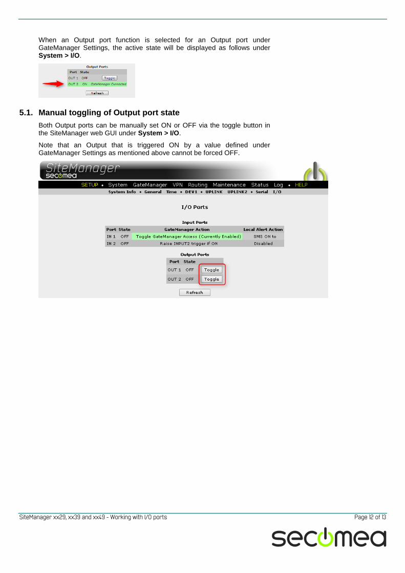
When an Output port function is selected for an Output port under GateManager Settings, the active state will be displayed as follows under System > I/O.
5.1. Manual toggling of Output port state Both Output ports can be manually set ON or OFF via the toggle button in the SiteManager web GUI under System > I/O.
Note that an Output that is triggered ON by a value defined under GateManager Settings as mentioned above cannot be forced OFF.

SiteManager xx29, xx39 and xx49 - Working with I/O ports Page 13 of 13
Notices
Publication and Copyright © Copyright Secomea A/S 2011-2015. All rights reserved. You may down-load and print a copy for your own use. As a high-level administrator, you may use whatever you like from contents of this document to create your own instructions for deploying our products. Otherwise, no part of this docu-ment may be copied or reproduced in any way, without the written consent of Secomea A/S. We would appreciate getting a copy of the material you pro-duce in order to make our own material better and – if you give us permis-sion – to inspire other users.
Trademarks GateManager™, SiteManager™ and LinkManager™ are trademarks of Secomea A/S. Other trademarks are the property of their respective owners.
Disclaimer Secomea A/S reserves the right to make changes to this publication and to the products described herein without notice. The publication of this docu-ment does not represent a commitment on the part of Secomea A/S. Con-siderable effort has been made to ensure that this publication is free of inaccuracies and omissions but we cannot guarantee that there are none.
The following paragraph does not apply to any country or state where such provisions are inconsistent with local law:
SECOMEA A/S PROVIDES THIS PUBLICATION "AS IS" WITHOUT WARRANTY OF ANY KIND, EITHER EXPRESS OR IMPLIED, INCLUDING, BUT NOT LIMITED TO, THE IMPLIED WARRANTIES OF MERCHANTA-BILITY OR FITNESS FOR A PARTICULAR PURPOSE
SECOMEA A/S SHALL NOT BE LIABLE FOR ANY DIRECT, INDIRECT, INCIDENTAL, CONSEQUENTIAL, OR OTHER DAMAGE ALLEGED IN CONNECTION WITH THE FURNISHING OR USE OF THIS INFOR-MATION.
Secomea A/S Denmark CVR No. DK 31 36 60 38 Tel.: +45 88 70 86 50 Fax: +45 88 70 80 60 E-mail: [email protected] www.secomea.com