site survey guidelines for wlan deployment
TRANSCRIPT

Site Survey Guidelines for WLAN Deployment
Document ID: 116057
Contributed by Patrick Croak and Young Kim, Cisco TAC Engineers.Apr 10, 2013
Contents
IntroductionPrerequisites Requirements Components Used ConventionsTypes of Site Surveys Passive Survey Active Survey Predictive SurveysPlan for the SurveyChecklist of Base Items to ask the Site Survey ProviderMistakes That Make a Survey Poor Calibration Signal Propagation Survey Path Incomplete Walking Path Complete Walking PathConsiderations for CapacityChannel Scanning, SSID, and Adapter TypeKey Items to Check in a Post−validation Survey Coverage Overlap Signal−to−Noise Ratio Noise Floor Bleed Through Rogues and InterferersUse WLC Link−Test to Assist with Coverage Assessment How to check for AP coverageUnderstand Wireless Data Rates Coverage (Cell Size) Management Frames Multicast DeliveryCommon Troubleshooting Scenarios Verification of Signal Strength inSSIDer Neighbor List on 792x PhoneRelated Information
Introduction
The first step in a wireless LAN (WLAN) deployment is to ensure that desired operation begins with a sitesurvey to assess the Radio Frequency (RF) behavior in a specific environment. Many issues can arise in awireless network due to poor planning and coverage.

It has been discovered that many site surveys are not performed properly or the site survey is omittedaltogether. The intended purpose of this document is to provide guidelines for proper planning, preparation,and identification of the key items to check through the analysis of a survey report.
Prerequisites
Requirements
Cisco recommends that you have knowledge of these topics:
IEEE 802.11 Wireless• Wireless LAN Design•
Components Used
This document is not restricted to specific software and hardware versions.
The information in this document was created from the devices in a specific lab environment. All of thedevices used in this document started with a cleared (default) configuration. If your network is live, make surethat you understand the potential impact of any command.
Conventions
Refer to Cisco Technical Tips Conventions for information on document conventions.
Types of Site Surveys
There are three types of surveys: Passive, Active, and Predictive.
Passive Survey
Passive surveys are surveys that are performed with a listen−only mode. The survey client never associates tothe access point (AP). Such surveys can be helpful when you look for rogue devices or you want a good gaugeof downlink RF coverage from the infrastructure devices.
These can be accomplished with a passive survey:
Identify rogues• Locate RF trouble zones quickly• Validate final RF setting• Perform initial surveys•
The most significant loss of information with passive surveys is uplink information, Physical (PHY) rateboundaries and retransmission. PHY rates are generally based on RF signal and noise levels. A passive surveyonly reports signal propagation for beacons measured by particular clients. PHY rates can only be measuredby actual data that is sent to and from an AP.
Active Survey
Active surveys are performed with the survey client associated to the APs used throughout the survey. When aclient is associated, it performs all the tasks a typical 802.11 client performs, which includes rate shifting datarates as the RF condition changes and performs retransmissions. Active surveys are commonly used for new

WLAN deployments because they provide the most details upon which to base a design.
There are two main methods used in active surveys:
Basic Service Set Identifier (BSSID) Method: This method locks a client into an AP's radio MACaddress and prevents the client from roaming.
1.
Service Set Identifier (SSID) Method: This is more commonly used for post−deployment scenariosand used to survey multiple APs. It enables the survey client to associate to an SSID where the clientroams between multiple APs.
2.
Predictive Surveys
Predictive surveys are performed with a software program. The program uses the information about thecoverage area to perform AP placements based on RF algorithms. These surveys are typically void of any typeof field measurements.
The best times to incorporate a predictive survey include:
When the deployment environment has not yet been built.• In order to obtain a budgetary environment for WLAN−related hardware.• When roaming requirements are less stringent.•
Prepare for the Survey
Use this checklist to help you prepare your survey.
Identify Primary Requirements:
RF application needs (voice, data, location, etc.)• Type of facility• Type of client devices• Industry vertical• Customer questionnaire•
Identify Customer Facility Requirements
Single−floor• Multi−floor• Campus (indoor and outdoor)• Warehouse• Obtain digital floor plans from customer•
Identify Requirements for Type of Client Devices
Minimum Received Signal Strength Indicator (RSSI)• Minimum Signal−to−Noise Ratio (SNR)• Delay and Jitter tolerance• Maximum transmit (Tx) power•
Plan for the Survey
Use this checklist to plan for your survey.
Initial Walkthrough
Access building type• Anticipate difficult zones• Confirm surveyed areas• Check details of area not mentioned on the main coverage map• Check unexpected roaming path•
Select Proper Survey Model
Data• Voice• Location•
Determine Proper Deployment Characteristics
Dense deployment• Highly mobile (Many cells; high−reliability; fast−moving clients) versus nomadic (temporaryposition)
•
Predictive versus Actual•
Specify the tools to complete the survey
Obtain digital floor plans from customer• Spectrum analysis tool like Cisco Spectrum Expert• Professional survey tool such as Airmagnet Survey or Ekahau Site Survey•
Define Client Devices to be Deployed
Maximum Tx Power level• Receiver Sensitivity• Antenna•
Determine Physical requirements:
Power• Understand cable considerations• Mounting considerations• Outdoor grounding and lightning protection• Consider placement of additional APs for monitoring and sniffing•
Checklist of Base Items to ask the Site Survey Provider
Frequency bands to be used: 2.4 GHz, 5 GHz.• Tools to be used in order to complete the survey, such as Airmagnet, Ekahau, and so on.• Active or passive survey.• Auto sampling.• Type of adapter to be used to perform the survey.• The coverage areas that are 'in−scope' or 'out−of−scope', such as stairwells, elevators, electric rooms,air shafts, mechanical areas, and so on.
•
Heat map that displays RF coverage for all 'in−scope' areas with coverage set at the target RSSI forcell edge with a signal legend.
•
Heat map that displays SNR for all 'in−scope' areas with the target SNR and an SNR legend.•

Heat map that displays the noise floor for all 'in−scope' areas with the target noise floor set and anoise floor legend.
•
Spectrum Analysis screenshots and recordings of possible sources of interference. Define what isdesired in the analysis − Fast Fourier Transform (FFT), spectrograms, duty cycle, max hold, and soon.
•
Identify and list possible sources of interference. A walkthrough should be performed through thefacility. Ask about and look for possible sources of interference, such as microwave ovens, cordlessphones, and so on.
•
The AP hardware to be used. For example, the heat maps may look different for Aironet 3500 SeriesAccess Points verses Aireonet 3600 Series Access Points. The AP should be selected to match the APthat is planned to be purchased and deployed.
•
If a passive survey is performed, define how many AP's at a time are planned to be used, one or three.Three is quicker than one, but the AP placements might be sub−optimal.
•
Identify the type of survey to be conducted: voice, location, or data only.•
Mistakes That Make a Survey Poor
Mistakes can be made with the use of survey tools that are able to make a site survey report look good. Thesemistakes can make an entire floor or building appear to have sufficient coverage when, in reality, clientdevices in certain areas might have very weak coverage.
You should always request the actual survey data files with the survey report so the actual data can bere−examined for mistakes and issues that are not shown in the survey report.
Calibration
The map calibration in a survey tool allows you to define the correct distance between two points on the map.For example, you can draw a line across a 40−foot wall on the map and specify that the distance of the linerepresents 40 feet. The rest of the map can be rescaled based on this defined distance.
If the map is not properly calibrated, the heat maps generated from the AP do not represent the correctdistance. Data gathered from a map that is not properly calibrated results in a completely inaccurate surveyreport. It is recommended to verify the map calibration in survey reports where the heat maps do not lookcorrect. Most cases you see a single data point or AP radio provides much larger coverage in the survey mapwhen compared to actual coverage. It is a good practice to view AP heat maps one at a time and verifywhether the coverage looks too big or too small. For example, you might see an AP heat map cover an entirefloor; this could be an indicator that the calibration is not properly configured.
You might also notice maps that do not look accurate where the image looks stretched or skewed. This can bean indication of an invalid map that is not properly scaled. Best practice to always use a long distance on themap when you measure a distance that is used for calibration as this results in better accuracy. Discrepanciesby even a millimeter with the use of a small doorway has a more harmful result when compared todiscrepancy by a millimeter when an entire hallway is used. The default dimensions after a drawing isimported is 120 feet by 120 feet. If you see a map still calibrated at 120 feet by 120 feet, it is an indication thatthe map is not calibrated.
Note: You cannot recalibrate the map after the survey is performed to repair survey data that was taken whenthe map calibration was not properly scaled. You must correct the map calibration and perform a new survey.
Figure 1: Improperly−scaled Map with default dimensions of 120 feet by 120 feet

Figure 2: Properly Calibrated Map

You should always verify the map calibration. Measure the distance between two points on the map and verifythe accuracy. You can use the 'measure tool' in AirMagnet to measure the distance between the desired pointson the map.
Figure 3: Measure Tool
Signal Propagation
The 'Signal Propagation Assessment' allows the site survey application to predict signal propagation betweendata points. If this value is too high, the results render inaccurately and might show acceptable signal levels inareas where there is insufficient coverage. When you view a report where you see the signal extend far outsidethe building walls or areas where data points were taken, might be an indication that the 'Signal PropagationAssessment' is set too high. The default for AirMagnet is 40 feet, which might not be precise enough foraccurate results. A setting of 15 to 20 feet provides results that are more accurate. As mentioned earlier, it isalways a best practice to view AP heat maps one at a time. You should take note how far the signal propagatesfrom a single AP, and also note that you should observe that the signal becomes weaker as you move further

away from the AP. You can change the 'Signal Propagation Assessment' value to a different value after asurvey has been completed without the need to perform the survey again.
Figure 4: Signal Propagation should be changed from the defaults
Survey Path
It is important to verify the survey path on which the data points were taken. The survey path should follow avalid walking path and should not have paths that go through walls. The survey path should also have awalking path that shows data points collected inside rooms and offices where there is desired coverage. It ispossible that you do not have proper coverage in a room or area that shows coverage but does not have awalking path or data point. You should also verify that the doors to the rooms and offices were closed whenthe data points were collected. Assess the survey path in order to verify how often data points are collected.
Incomplete Walking Path
Data points were not taken in all locations; this includes inside the offices along the bottom of the floorplan.Areas in white signify that no measurements were taken.
Figure 5: Incomplete Walking Path

Complete Walking Path
Data points were captured inside the offices along the bottom of the floorplan. This is denoted by the red andblue line that can be seen inside the rooms.
Figure 6: Complete Walking Path
Considerations for Capacity
For areas such as conference rooms, which might have high client density, it is important to consider clientcapacity needs as well as coverage. When you consider client capacity, it is important to check whichapplications are used on the client devices in order to understand how much bandwidth is required.
Channel Scanning, SSID, and Adapter Type
It is important to check the 'channel scan list' to ensure that all of the channels that are in use are included inthe list. It is recommended that you scan only the channels that are in use by the wireless infrastructure. Youmight receive inaccurate readings if you walk too fast between data points and do not give the adapter enoughtime to complete the entire scan list. If you scan for rogue devices, you must be aware that rogue devices onchannels that are not in the scan list are not detected.
Figure 7: Channel Scan List

Another recommendation is to only scan or view heat maps for SSIDs that are provided by the wirelessinfrastructure. This is very important in buildings where an adjacent floor belongs to another party. The bleedthrough from their wireless infrastructure might appear to be your own coverage.
You must take note on what adapter was used in a site survey. The adapter should have similar characteristicsto the adapters on the devices that are actually to be used in the wireless network. You should always verifywhat type of client adapter was used throughout the survey. A client adapter with a better receiver sensitivityand stronger antenna does not provide accurate results to compare against clients that are actually used inproduction.
Key Items to Check in a Post−validation Survey
The primary objective of a post−validation site survey is to provide detailed information that addresses thecurrent RF coverage and determines whether there is sufficient coverage to support the network designrequirements.
Post−validation surveys should also include information that addresses interference sources, equipmentplacement, and rogue devices. The site survey documentation serves as a guide for the verification of thewireless infrastructure. This document discusses the major topics that should be covered in a post−validationsurvey report.
Coverage
Coverage defines the ability of wireless clients to connect to a wireless AP with a signal strength and qualityhigh enough to overcome the effects of RF interference. The edge of the coverage for an AP is based on thesignal strength and SNR measured as the client device moves away from the AP.

The signal strength required for good coverage varies dependent on the specific type of client devices andapplications on the network.
To accommodate the requirement to support wireless Voice over IP (VoIP), refer to the RF guidelinesspecified in the Cisco 7925G Wireless IP Phone Deployment Guide. The minimum recommended wirelesssignal strength for voice applications is −67 dBm and the minimum SNR is 25 dB.
The first step in the analysis of a post site survey is to verify the 'Signal Coverage'. The signal coverage ismeasured in dBm. You can adjust the color−coded signal gauge to your minimum−allowed signal level toview areas where there are sufficient and insufficient coverage. The example in Figure 8 shows blue, green,and yellow areas in the map have signal coverage at −67 dBm or better. The areas in grey on the coveragemaps have deficient coverage.
Figure 8: Signal at −67 dBm
When you check the signal coverage, make sure the AP's radio transmit power does not use a transmit powergreater than what the client devices can support. For example, by default, the Cisco Unified Wireless IP Phone7925G uses the highest available transmit power by default (17 dBm / 50 mW for 2.4 GHz and 16 dBm / 40mW for 5 GHz). It is possible to have a survey report that shows good coverage in all areas; however, if youhave APs that operate at the highest transmit power, you might still experience uplink issues where the clientdevices do not support the same transmit power. For areas where there is deficient coverage, and you increasethe AP transmit power to levels that the client devices cannot support, this only increases coverage on thedownlink.
Figure 9: AP Transmit Power Levels

Overlap
Check the site survey to determine whether the channel overlap is adequate for devices to roam to the next APbefore the signal is lost from the previous AP. For example, based on the RF guidelines specified in the Cisco7925G Wireless IP Phone Deployment Guide, you must use non−overlapping channels and allow at least 20percent overlap with adjacent channels when phones are deployed in the 802.11b/g environment. For voicedeployments, it is recommended that the cell edge should be at −67 dBm with 20 percent overlap.
Figure 10: Channel Overlap
Signal−to−Noise Ratio
SNR is the ratio of a given transmitted signal to the background noise on that channel. The RF guidelinesspecified in the Cisco 7925G Wireless IP Phone Deployment Guide require a minimum SNR of 25 dB (25 =−92 dBm noise level with −67 dBm signal). You can view the SNR heat map on the AirMagnet toolbarpull−down menu and change the selection from Signal Coverage to SNR.
You can also adjust the color−coded signal gauge to your minimum−allowed SNR level to view areas wherethere is sufficient and insufficient SNR. Blue, green, and yellow areas in the map shown in Figure 11 haveSNR of 25 dB or better. Areas in grey on the map do not meet the minimum SNR of 25.
Figure 11: SNR at 25 dB

Noise Floor
The noise floor is a mixture of all of the background RF radiation found in the environment that surrounds thesystem in use. RF signals must be higher than the noise floor in order to be detectable as a valid, useful signalby a receiver. For an SNR of 25 dB and signal at −67 dBm the noise level must not exceed −92 dBm. You canview the 'noise floor' heat map on the AirMagnet toolbar pull−down menu and change the selection to NoiseFloor.
You can also adjust the color−coded signal gauge to your minimum−allowed noise floor level to view areaswhere the noise floor level exceeds −92 dBm. Grey areas in the floor shown in Figure 12 have noise levelsthat do not exceed −92 dBm. Orange and yellow areas have a noise level that exceeds −92 dBm.
Figure 12: Noise Floor at −92 dBm

Bleed Through
The RF signal can bleed through from floors above and below. It is important to know how much signalbleeds through the floors because this can cause co−channel interference and can also be the reason why anAP radio operates at a very low power level. Additionally, this might be the reason why it appears thatadjacent APs on the same floor have dynamically chosen the same channel. You can view a map with the APplacements on each floor and verify that the AP placements are not stacked directly above or below the sameAP placements on a given floor. AP placements across floors should be staggered to provide better coverage.
You can check the AP radio neighbor list in order to verify bleed through and verify whether you detect APsthat are on different floors at a strong signal level.
The Cisco WLC Config Analyzer on the Cisco Support Community provides a detailed picture of APneighbor information.
Rogues and Interferers
Rogue APs are wireless APs that have been installed on an enterprise network without the authorization of theenterprise information technology department. Most rogue APs are not installed securely and can be used byoutsiders to gain access to an enterprise network.
In addition to the security risk posed by these devices, rogue APs are a source of co−channel and adjacentchannel RF interference, which degrades the performance of the enterprise WLAN. If there is not a businessjustification for these APs, they should be disconnected immediately from the network. When disconnected,this improves the overall network security and reduces RF interference with nearby infrastructure APs. If,however, these Aps do serve a required business function, you should investigate the prospect to integrate theapplication into the current corporate WLAN infrastructure.
A separate walkthrough is normally completed with Spectrum Experts in order to detect and record roguedevices and interferers, which gives you a snapshot of what was detected at that time.
Figure 13: Spectrum Experts
Do not rely only on this report or continuously rely on the infrastructure to detect and report interferers androgue devices. Rogue devices that are detected by the infrastructure devices should be reported to amanagement system for further triage and investigation. Figure 14 provides an example of the NetworkControl System (NCS) security summary tab.
Figure 14: NCS Security Summary Tab

;
Use WLC Link−Test to Assist with Coverage Assessment
In order to determine whether the current AP coverage is sufficient for the applications that run on a client, theWLC provides a user−friendly link test tool.
How to check for AP coverage
Step 1: With the client associated to an AP, and from the MAC address that matches the client, select WLC >Monitor > Clients. The Client Details are displayed as shown in Figure 15.
Step 2: Click the Link Test button and run the link test. This action performs a bi−directional link test thatdetermines the current coverage of the client. If there are no lost packets, then try to move the client awayfrom the AP in order to determine whether there is any additional range available while enough signal ismaintained to have quality application performance.
Figure 15: Client Details with Link Test Option

One coverage goal is to require a signal of −67 dBm RSSI or better to the AP, with an assumption that a noisefloor of −92 dBm, for an SNR of 25 dB. When you perform coverage tests on 2.4 GHz, it is recommended tohave the lower data rates disabled. This is because the −67 dBm RSSI coverage area is much larger at one (1)Mbps data rate than 12 Mbps. This is a range versus bandwidth design consideration. Dense 2.4 GHznetworks might have high channel utilization. The most effective way to reduce channel utilization is toremove lower data rates.
Understand Wireless Data Rates
Wireless data rate configurations are one of the most critical tools available to tune and optimize wirelessnetworks. The choice of data rate directly impacts coverage and performance; therefore, it is essential tounderstand how changes to data rates impact an environment.
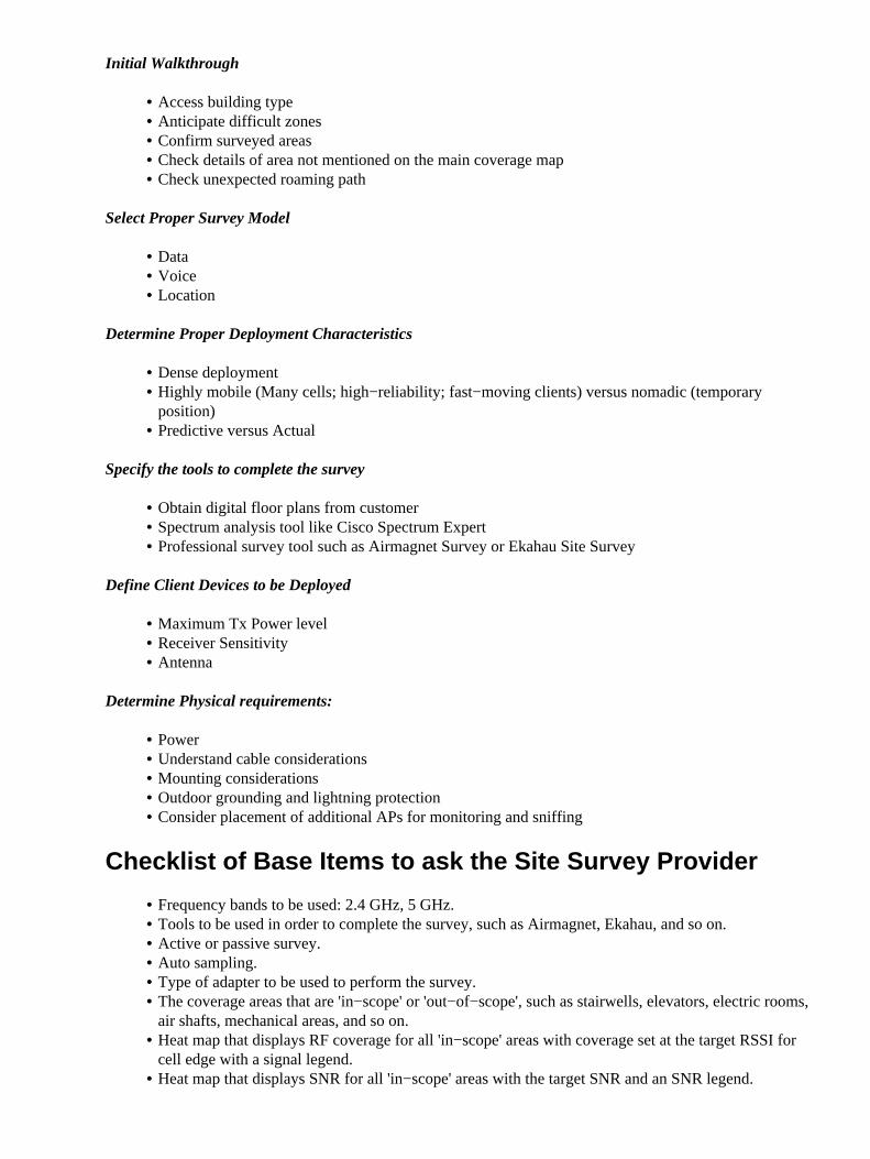
Coverage (Cell Size)
Lower data rates can be demodulated across greater distances than higher data rates. This is because of thelower complexity encoding schemes � the signal can be understood at a lower SNR. Enable lower data ratesin order to increase the effective range of the AP; disable the lower data rates in order to decrease the effectiverange of the AP.
Figure 16: Coverage (Cell Size)
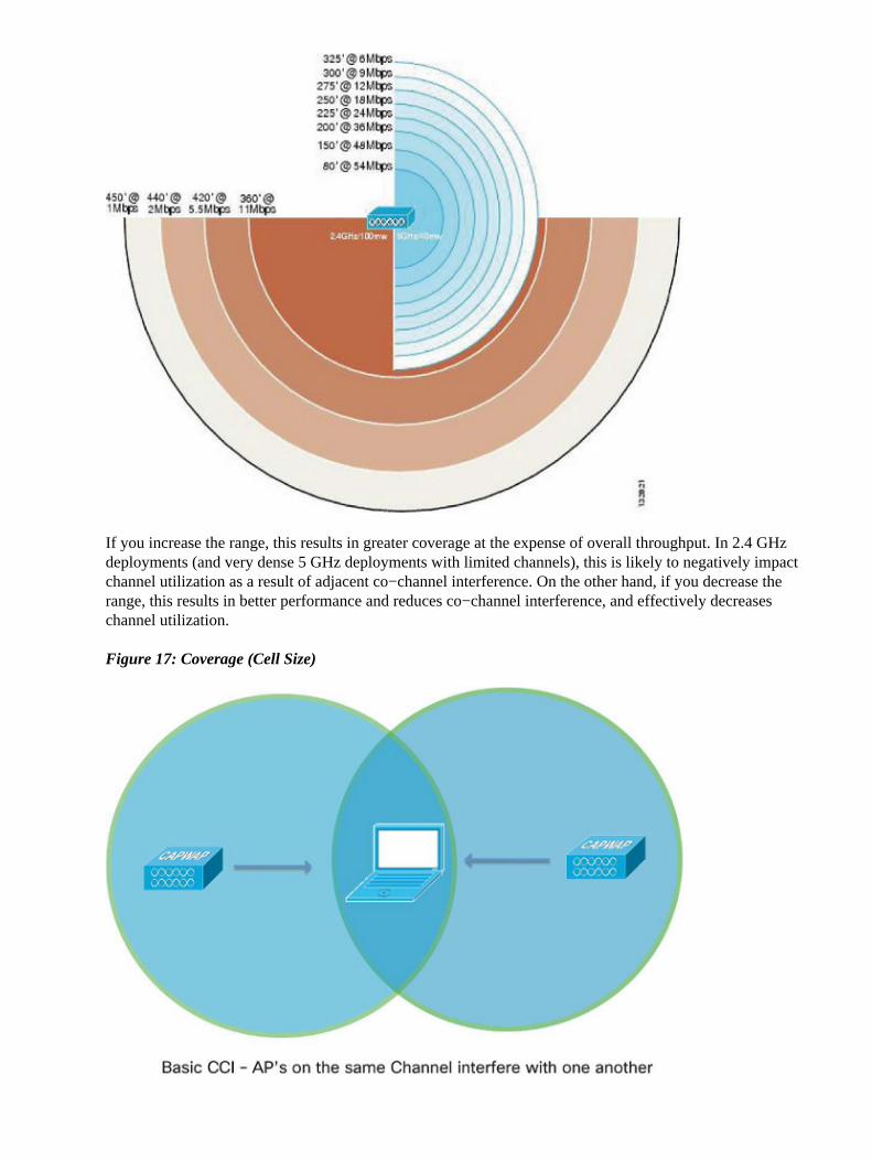
If you increase the range, this results in greater coverage at the expense of overall throughput. In 2.4 GHzdeployments (and very dense 5 GHz deployments with limited channels), this is likely to negatively impactchannel utilization as a result of adjacent co−channel interference. On the other hand, if you decrease therange, this results in better performance and reduces co−channel interference, and effectively decreaseschannel utilization.
Figure 17: Coverage (Cell Size)

The key is to balance these options in order to achieve the best performance based upon the desired APdensity and client/application requirements. For example, if you have voice services in the environment, youare likely to have a higher density deployment and should disable the lower data rates to improve performance(guideline for 792x is 12 Mbps as lowest). If you have a warehouse with old 802.11b scanners, obviously youmust keep the lower rates enabled. Version 7.2 of Wireless LAN Controller software enhances our control ofthe environment through the use of RF profiles, which allows you to set data rates on a per AP group basis. Ingeneral, most deployments set the lowest enabled rate as the mandatory rate. High density and multicastenvironments might have multiple higher mandatory rates. Refer to the Multicast Delivery section in thisdocument for more details.
Management Frames
802.11 management frames are sent at the lowest mandatory (basic) data rate. The primary concern with thisis beacon traffic. For example, if one (1) Mbps is defined as mandatory in a dense deployment with six (6)SSIDs, then 67 percent of airtime (bandwidth) is used on beacons alone. If 12 Mbps is the lowest mandatoryrate, then only five (5) percent of airtime is consumed by beacons. When you disable the lower data rates andlimit the number of SSIDs, this reduces time spent on management traffic and allows for more bandwidth forthe connected clients.
Figure 18: Management Frames
Multicast Delivery
In general, Multicast/Broadcast frames are sent at the highest mandatory (basic) data rate. There is anexception if there are current associated clients that transmit at a rate lower than the highest mandatory rate. Inthis situation, the AP sends Multicast/Broadcast frames at the highest mandatory rate that is below or equal toall of the current client transmission rates.
For example, the highest mandatory rate is 24 Mbps and lowest mandatory is set to six (6) Mbps. If all clientson that BSSID transmit at 24 Mbps or higher, then use 24 Mbps to transmit multicast. But, if any one clientrate shifts down to six (6) Mbps, then the transmission occurs at six (6) Mbps. Otherwise that client cannotreceive it.

Change the mandatory rates in order to modify multicast performance. When you set high mandatory rates,this allows higher bandwidth multicast streams to be delivered, although all clients might not receive thestream very reliably. If you set lower mandatory rates, this allows the stream to be delivered to lower signalstrength clients at the expense of bandwidth performance.
Common Troubleshooting Scenarios
Suspect poor coverage/not enough AP density � If AP transmit power is already at the maximum,you can enable the lower data rates to allow clients to connect from farther away. This has a negativeimpact on performance, but it can help the customer understand that additional APs might benecessary.
1.
High Channel Utilization � In order to attempt to reduce channel utilization and improveperformance, disable the lower data rates. Ask the customer if they have any 802.11b/legacy clientsbefore you make this change, to avoid problems.
2.
Large number of SSIDs � Try to reduce the number of SSIDs that are broadcast. AP groups mighthelp. Every SSID has 10 beacons to transmit per second by default, so you can save some airtime.
3.
Multicast traffic � If devices do not receive the multicast stream reliably, you might need to lower themandatory data rates. If the multicast stream is bandwidth intensive, such as High Definition (HD)video, you might need to set a higher rate to mandatory in order to improve performance.
4.
Verification of Signal Strength
Use the software application inSSIDer.1. Use the neighbor list on a Cisco 792x Wireless Phone.2.
inSSIDer
inSSIDer is a Wi−Fi scanning application developed by MetaGeek. It is compatible with Windows XP,Windows Vista, and Windows 7 (32 and 64 bit). It allows you to track received signal strength with thewireless adapter that is already installed. You can sort the information on many criteria, which includes MACaddress, SSID, Channel, RSSI, and Time.
Note: inSSIDer is not a full solution for wireless packet and spectrum analysis.
inSSIDer can be downloaded at MetaGeek.
When you have downloaded and installed inSSIDer, you can see the home screen as shown in Figure 19.
Figure 19: inSSIDer Home Screen

The various filters that you can apply are located at the top of the screen. In Figure 20, the filter is set on theSSID guestnet. Filter on the SSID that you want to measure to avoid any incorrect results from nearby roguewireless networks. You can also filter by channel, network type (Infrastructure/Adhoc), and Security (Open,WEP, WPA/WPA2 Personal/Enterprise).
inSSIDer can show a graph of the signals strength and channel information for ease of analysis. In theexample in Figure 20, it shows the filter is set on SSID guestnet on the 5 GHz Channels tab.
Figure 20: inSSIDer guestnet 5 Ghz Channels Tab

For best scanning performance, be sure to connect your workstation to the SSID you want to verify. Thisensures faster processing of Beacon and Probe Responses. Remember, for voice services, the goal is to have atleast two (2) APs heard at −67 dBm or greater at all times. In this example, voice services fail in thisenvironment, as there is only one (1) signal strength greater than −67 dBm (with the assumption of a noisefloor of −92 dB, which allows for a SNR of 25 dBm).
You can verify whether the signal strength varies over time in your environment, if you suspect any RF issuescaused by environmental changes.
Figure 21: inSSIDer Verify Signal Strength

Neighbor List on 792x Phone
The Cisco Unified Wireless IP Phone 7925G, 7925G−EX, and 7926G can be utilized to verify coverage withthe Neighbor List menu.
In order to access the neighbor list menu on the Cisco Unified Wireless IP Phone 7925G, 7925G−EX, and7926G, select Settings > Status > Neighbor List. The connected AP is highlighted in red. With the Auto scanmode enabled (by default), the Cisco Unified Wireless IP Phone 7925G, 7925G−EX, and 7926G idle (not oncall), Auto scan only scans when the current signal lowers to the scan threshold, so only a single AP is visiblein the list.
In order to view all APs in the neighbor list menu with Auto scan mode, place a call from the Cisco UnifiedWireless IP Phone 7925G, 7925G−EX, and 7926G, where scanning occurs constantly while the phone call isactive in Auto scan mode. With Continuous scan mode, the Cisco Unified Wireless IP Phone 7925G,7925G−EX, and 7926G always scans, regardless of call status (idle or on call) or current AP signal level(RSSI).
With Unified Wireless IP Phone 7925G, 7925G−EX, and 7926G Release 1.4(2), neighbors are listed in orderfrom the strongest signal to the weakest signal with the use of Auto−RSSI, 802.11a or 802.11b/g mode. If youuse Auto−a or Auto−b/g mode, then the neighbors are displayed in this order:
Preferred Band Neighbors with >= −67 dBm RSSI.• Less Preferred Band Neighbors with >= −67 dBm RSSI.• Preferred Band Neighbors with < −67 dBm RSSI.• Less Preferred Band Neighbors with < −67 dBm RSSI.•

Figure 22: Neighbor List
Note: The Channel Utilization (CU) metric shown in Figure 22 refers to the Quality of Service (Qos)Enhanced Basis Service Set (QBSS) index, which has a maximum value of 255. Divide the value reported inCU by 255 to achieve a channel utilization percent. The guideline for voice deployments is to keep CU under105 (105/255 = approximately 41 percent).
Related Information
HIgh Density Wirleless LAN Design Guide• Cisco 7925G Wireless IP Phone Deployment Guide• Cisco WLC Config Analyzer on the Cisco Support Community• Technical Support & Documentation − Cisco Systems•
Updated: Apr 10, 2013 Document ID: 116057