site preparation guide - weiland sliding doors and windows
TRANSCRIPT

Site Preparation Guide
Weiland Sliding Doors and Windows, Inc.Oceanside, CA 92054
(760) 722-8828www.WeilandSlidingDoors.com

INDEX
SECTION 1: FOUNDATION PREP: ............................................................................1Track System – Determining the Slot Depth .................................................................1Framing Considerations ..................................................................................................2Header ...............................................................................................................................2Side Jamb ..........................................................................................................................2Side Jamb ..........................................................................................................................2Pockets ...............................................................................................................................3SECTION 2: PRE-INSTALLATION CHECK LIST: ...................................................4General Information .........................................................................................................4Tools.....................................................................................................................................5
1
Foundation Prep Track System
One of the unique aspects of the Weiland Lift Slide system is the minimal track that is exposed afterinstallation. To obtain this look and allow the large weight of the doors to travel smoothly, a rather uniquetrack system has been developed. This system has been developed with an easy installation in mind butthe system requires some pre installation planning.
The concrete/wood framing in this area should be of the highest quality.Reference the shop drawings when determining slot dimensions for both length and width of the track. Aslot needs to be prepared in the rough flooring.
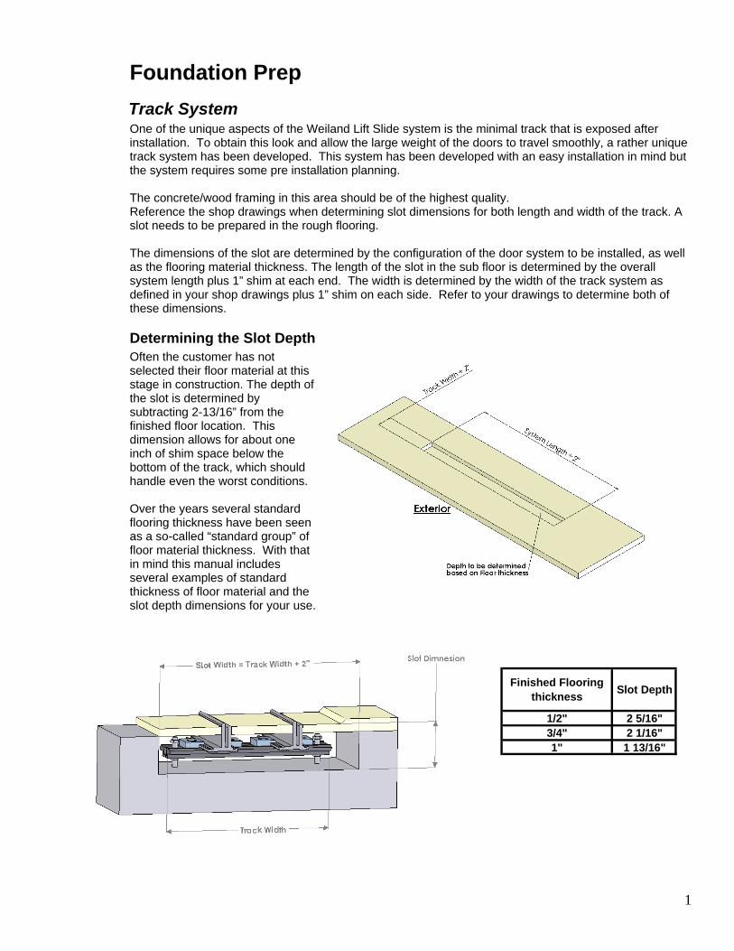
The dimensions of the slot are determined by the configuration of the door system to be installed, as wellas the flooring material thickness. The length of the slot in the sub floor is determined by the overallsystem length plus 1” shim at each end. The width is determined by the width of the track system asdefined in your shop drawings plus 1” shim on each side. Refer to your drawings to determine both ofthese dimensions.
Determining the Slot DepthOften the customer has notselected their floor material at thisstage in construction. The depth ofthe slot is determined bysubtracting 2-13/16” from thefinished floor location. Thisdimension allows for about oneinch of shim space below thebottom of the track, which shouldhandle even the worst conditions.
Over the years several standardflooring thickness have been seenas a so-called “standard group” offloor material thickness. With thatin mind this manual includesseveral examples of standardthickness of floor material and theslot depth dimensions for your use.
Finished Flooring thickness Slot Depth
1/2" 2 5/16"3/4" 2 1/16"1" 1 13/16"

2
Framing ConsiderationsFraming an opening for a Weiland Liftslide system has particular requirements. They occur in framing atthe header, at the side jambs and in the area of the pocket interlocks.
HeaderOnly minimal deflection may occur at the rough opening header. No deflection over the entireunsupported span can be greater than 1/8” once that header beam is fully loaded. Special care shouldbe taken in the case of a transom window set above the opening header.
The head track supplied with your Lift Slide is just a guide and cannot contact the door at all. Most of theservice callbacks related to “hard to move panels” are a result of the header sagging andconsequently restricting door operation.
In addition, the entireheader opening shouldbe covered with plywoodto accommodate installationof the mounting screws(not supplied) to theframing. This plywood-mounting surface should beas wide as the widest part ofthe head, as defined on yourshop drawings.
Side JambThe side jamb rough framing should be as wideas the supplied jamb in order to create a securemounting surface.
A continuous plane of material should be installedto accommodate the installation hardware (notsupplied) whose locations vary with system size.
3
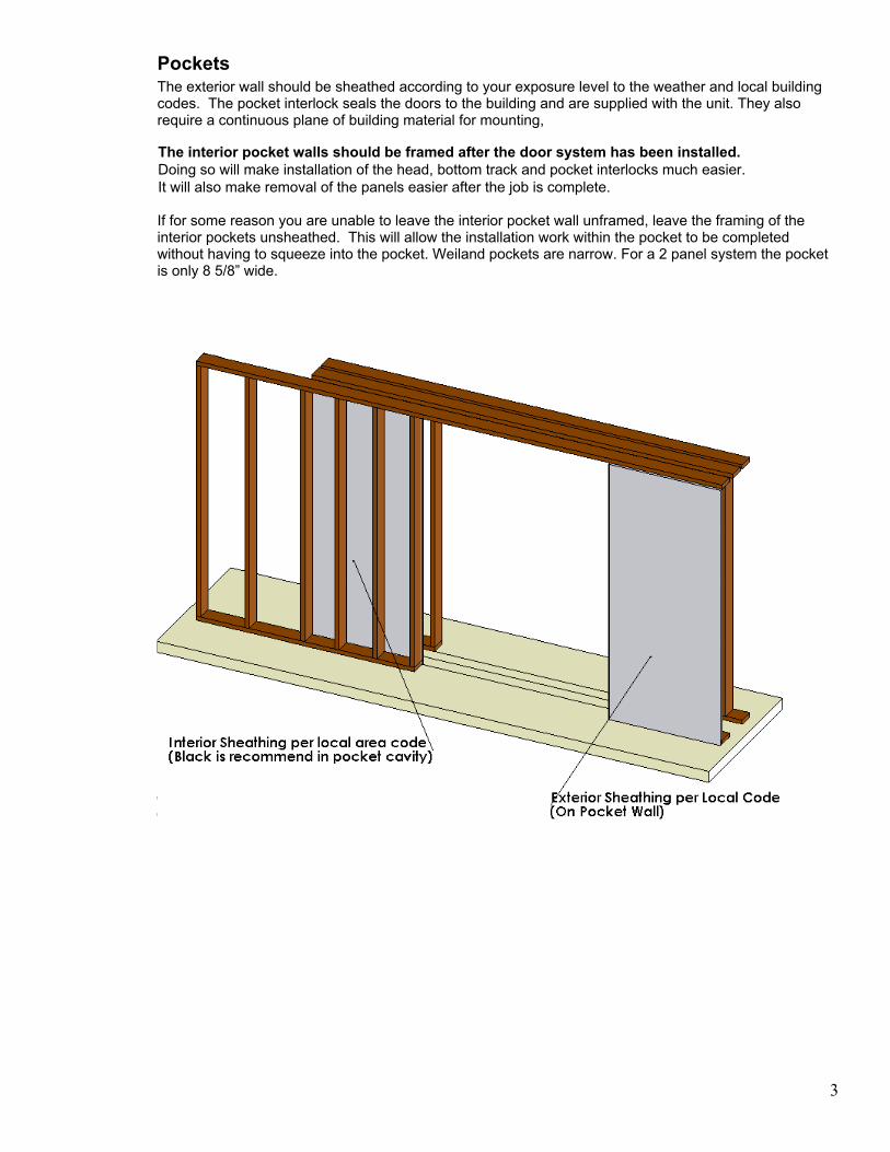
PocketsThe exterior wall should be sheathed according to your exposure level to the weather and local buildingcodes. The pocket interlock seals the doors to the building and are supplied with the unit. They alsorequire a continuous plane of building material for mounting,
The interior pocket walls should be framed after the door system has been installed. Doing so will make installation of the head, bottom track and pocket interlocks much easier. It will also make removal of the panels easier after the job is complete.
If for some reason you are unable to leave the interior pocket wall unframed, leave the framing of theinterior pockets unsheathed. This will allow the installation work within the pocket to be completedwithout having to squeeze into the pocket. Weiland pockets are narrow. For a 2 panel system the pocketis only 8 5/8” wide.

4
Pre-Installation Check List
General Information
Often shop drawings are revised so system dimensions may change during the order and design phase.Before you begin this checklist make sure you have the final approved shop drawings. All of theseitems should be correct before the installer arrives so that you are not paying him to make corrections ofthese items.
1. The rough opening is the correct size, plumb and square. This is critical as once the installer is on site,you will not want to pay him to adjust the rough framing prior to the installation or stand around while youadjust the framing
2. No sagging header. Take into account if the roof has been loaded or not. The maximum deflection overentire length of opening should not exceed 1/8” max. after the roof is loaded.
3. No bumps or arches on the sub floor.
4. Correct recess from finished floor location to bottom of slot. Minimums are listed on the drawing but moreis always better. You can adjust the track up and down easier than chip out concrete or reframe the slot.
5. The level of the finish floor needs to be determined ahead of time and noted somewhere near theopening. If the track will be embedded into concrete, the slot for the track needs to be set in the concreteaccording to the drawing. If the system will be over a framed truss structure, a way to contain the track toaccommodate the dry pack of concrete surrounding the track after installation should be determined.
6. The Weiland Lift Slide Door System may be built with a weep system. If so, the drain locations should beidentified so the drain tubing can be run before filling the track.
7. For pocketing systems, insure that the finished pocket width and depth is correct. These dimensions arereferenced in your drawings. The outside wall of the pocket needs to be framed in and sheathedaccording to the building codes in your area.
Wait to build the interior pocket walls until after the installation of the doors. This will allow easier accessto the exterior pocket walls for installation of the head and bottom track; easier installation of the panelsonce the head and bottom track have been installed.
8. Although less desirable, the interior pockets can be framed, but left unsheathed so installation work withinthe pocket can be performed more easily. A certain amount of the interior pocket wall surfaces will bevisible so it is best to paint the interior surfaces black. Do this before the doors are permanently installed.
9. Once your Weiland Door SystemTM arrives on site, unpack all components; check each against thepacking slip and lay all of it near the appropriate opening.
10. Finish the wood surfaces prior to installation. The warranty requires that the doors should be sealedwithin 24 hours of delivery because:
a. It protects the wood from swelling and contracting, which can damage the wood itself and causeproblems with operation.
b. Once the doors are installed, it is difficult to access the overlapping stiles on the doors.
c. Doors supplied open (no glass) are easy to remove until the glass is installed. Then it normallyrequires 2 to 3 people to remove and reinstall the panels.

5
11. Make several story poles to locate the top guide at the correct height over the bottom track.To determine the length of the story pole, measure the height of the panel and subtract 7/16”.(Panel height is noted on your shop drawings).
12. Either wood framing or a continuous plane of plywood should be in place to anchor the head and/or side jamb.
13. The location of the mounting holes, which are pre-drilled, is dependent on system length and as such the complete sheathing makes the installation easier.
This will allow mounting hardware (not supplied) to be placed where necessary.
TOOLS:
Standard framing contractor or a finish carpenter tools are required.
Some specific tools that must be on site include the following:
• Laser level (or a water level – long and short)
• Open end wrenches for the adjustments of the studs
• Concrete drill (1/2" diameter)
• Several tubes of quick set epoxy (Simpson works well)
• Plumb bob (several to place along length of head track)
• Several ladders to install head
• All fasteners that might be necessary for the installation. These should be on site prior to beginning the installation.
These may include: All tread ¼ 20 x 4” anchor bolts (if going into a concrete sub floor)
¼” – 20 nuts (2 for every all thread anchor bolt)
# 10 stainless steel screws at least 3 1/2 - 4” long.