site planning guidedublinohiousa.gov/dev/dev/wp-content/uploads/2018/03/18-015... · i site...
TRANSCRIPT

SITE PLANNING GUIDE
48’ MOBILE MRI SYSTEM
SIEMENS HARMONY 1.0T/SYMPHONY 1.5T (Transportable at Field)
Manufactured by
MEDICAL COACHES, INCORPORATED
Proper site preparation for special-purpose mobile units is critical to their successful operation. This guide has been assembled to provide you with detailed site planning and preparation data specifically for the SIEMENS MRI System installed in a Medical Coaches Mobile Unit. The information compiled and provided should be sufficient to cover most site planning requirements. If additional questions do arise, please contact Medical Coaches directly. See page 3. Medical Coaches continues to learn from our valued customers. We invite your comments and suggestions on any improvements to this document, and sincerely appreciate your past contributions. The confidential information contained herein is the property of Medical Coaches, Inc. and may only be used by our customers.
Part No. 118697 Rev. G JUN-15-00
i
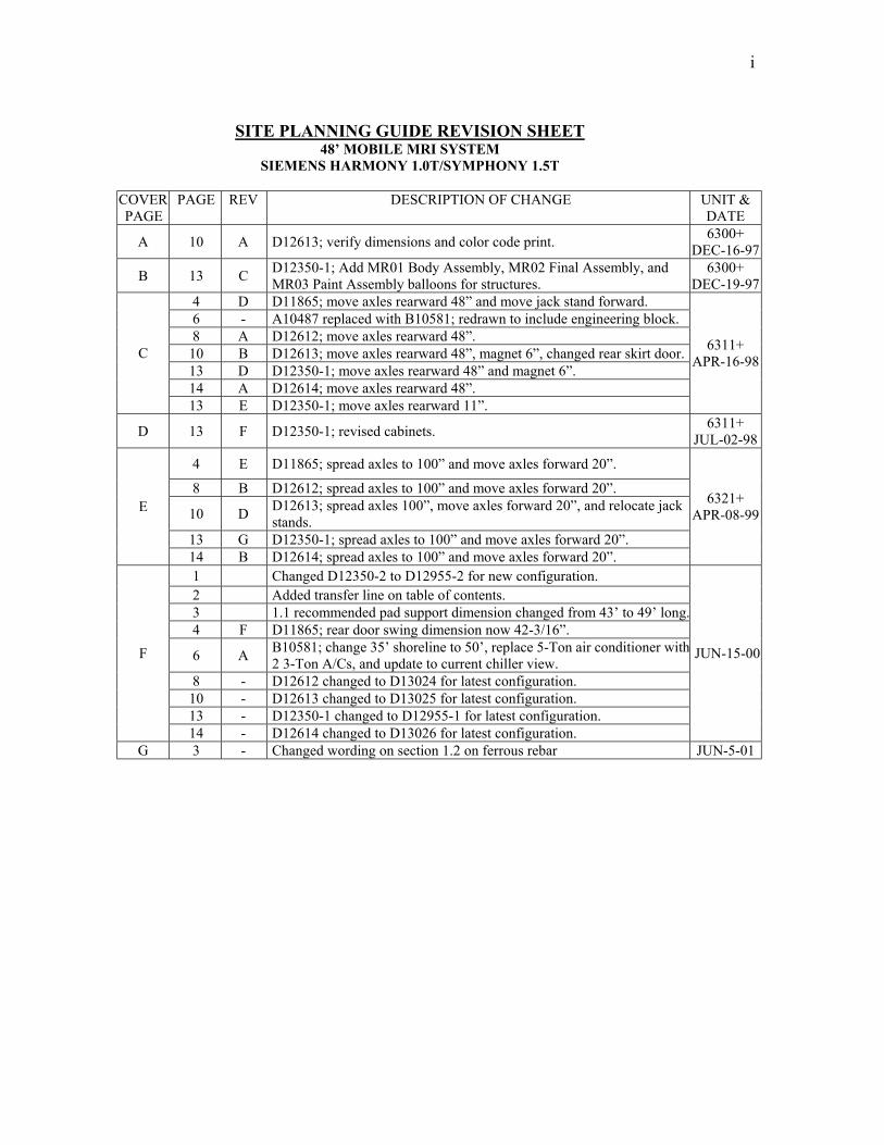
SITE PLANNING GUIDE REVISION SHEET
48’ MOBILE MRI SYSTEM SIEMENS HARMONY 1.0T/SYMPHONY 1.5T
COVER PAGE
PAGE REV DESCRIPTION OF CHANGE UNIT & DATE
A 10 A D12613; verify dimensions and color code print. 6300+ DEC-16-97
B 13 C D12350-1; Add MR01 Body Assembly, MR02 Final Assembly, and MR03 Paint Assembly balloons for structures.
6300+ DEC-19-97
4 D D11865; move axles rearward 48” and move jack stand forward. 6 - A10487 replaced with B10581; redrawn to include engineering block. 8 A D12612; move axles rearward 48”.
10 B D12613; move axles rearward 48”, magnet 6”, changed rear skirt door. 13 D D12350-1; move axles rearward 48” and magnet 6”. 14 A D12614; move axles rearward 48”.
C
13 E D12350-1; move axles rearward 11”.
6311+ APR-16-98
D 13 F D12350-1; revised cabinets. 6311+ JUL-02-98
4 E D11865; spread axles to 100” and move axles forward 20”.
8 B D12612; spread axles to 100” and move axles forward 20”.
10 D D12613; spread axles 100”, move axles forward 20”, and relocate jack stands.
13 G D12350-1; spread axles to 100” and move axles forward 20”.
E
14 B D12614; spread axles to 100” and move axles forward 20”.
6321+ APR-08-99
1 Changed D12350-2 to D12955-2 for new configuration. 2 Added transfer line on table of contents. 3 1.1 recommended pad support dimension changed from 43’ to 49’ long.4 F D11865; rear door swing dimension now 42-3/16”.
6 A B10581; change 35’ shoreline to 50’, replace 5-Ton air conditioner with2 3-Ton A/Cs, and update to current chiller view.
8 - D12612 changed to D13024 for latest configuration. 10 - D12613 changed to D13025 for latest configuration. 13 - D12350-1 changed to D12955-1 for latest configuration.
F
14 - D12614 changed to D13026 for latest configuration.
JUN-15-00
G 3 - Changed wording on section 1.2 on ferrous rebar JUN-5-01

2
TABLE OF CONTENTS 1.0. SUPPORT PAD REQUIREMENTS: 3 1.1. Recommended Support Pad .................................................................................................. 3 1.2. Support Pad Depth ............................................................................................................... 3 1.3. Support Pad Levelness .......................................................................................................... 3 Pad Requirements & Set Up Footprint; Drawing D11865.................................................... 4 1.4. Service Pad............................................................................................................................ 3 1.5. Dock Seal .............................................................................................................................. 3 2.0. CUSTOMER POWER REQUIREMENTS: 2.1. Electrical Service .................................................................................................................. 5 2.2. Configuration ........................................................................................................................ 5 2.3. Frequency.............................................................................................................................. 5 2.4. Shoreline Cable ..................................................................................................................... 5 2.5. Customer Receptacle............................................................................................................. 5 Site Electrical Requirements; Drawing B10581 ................................................................... 6 3.0. WATER REQUIREMENTS: 3.1. Trailer Water Supply Requirements...................................................................................... 7 3.2. Cold Weather Protection ....................................................................................................... 7 4.0. COMMUNICATION SERVICE: 4.1. Description of Phone Connectors Supplied ......................................................................... 7 4.2. Data Transfer Line ................................................................................................................ 6 5.0. SITE CLEARANCE REQUIREMENTS: 9 5.1. Trailer Clearance Around Unit; Drawing D13025................................................................ 10 5.2. Swing Dimension of Doors; Drawing D13025..................................................................... 10 5.3. Swing and Turning Radius; Drawing D11536...................................................................... 11 6.0. REGULATIONS .................................................................................................... 12
DRAWINGS & ILLUSTRATIONS INDEX: PAD REQUIREMENTS, TRAILER: Drawing D11865 ........................................................ 4 SITE ELECTRICAL REQUIREMENTS, Drawing B10581 .................................................. 6 TRAILER, STREETSIDE LOCATIONS; D12612 EXTERIOR ........................................................... 8 First Compartment ...... Fuel Tank Second Compartment .. Generator
TRAILER, CURBSIDE LOCATIONS; Drawing D13024 Exterior ....................................... 8 FIRST COMPARTMENT………..Electrical Supply (Shoreline) Electrical Controls and Steps. SECOND COMPARTMENT…….Patient Lift. THIRD COMPARTMENT……….SIEMENS Compartment/Storage and Water Connection.
`
TRAILER CLEARANCE REQUIREMENTS; Drawing D13025 .......................................... 10 MRI VAN OFF-TRACKING; Drawing D11536 .................................................................... 11 TRAILER FLOOR PLAN; Drawing D12955-1 ..................................................................... 13 LETTERING GUIDE; Drawing D13026 ................................................................................ 14

3
1.0. SUPPORT PAD REQUIREMENTS:
The following is a list of recommendations and requirements for a concrete support pad.
1.1. RECOMMENDED SUPPORT PAD: A full pad measuring 49’ long by 10’ wide should be located as shown on the drawing on page 4. Minimum support pads (cross-hatched area on drawing) are also shown. The minimum pads are not recommended because they may not accommodate future mobile systems servicing the site.
1.2. SUPPORT PAD DEPTH:
Recommendations for the length and width of pad are given above. However, the depth should be determined by a local contractor based upon the weight distribution information given on the drawing on page 4 and existing site conditions. If ferrous rebar is to be used in concrete pad, contact Siemens or Medical Coaches, Inc. about field setup specifications.
1.3. SUPPORT PAD LEVELNESS: The SIEMENS’ Mobile MRI System requires that the support pads be LEVEL FOR PROPER OPERATION. The pad must not exceed .25 inch deviation in 10 feet 0 inches.
! CAUTION !
STRICT ATTENTION MUST BE PAID TO PAD LEVELNESS! FAILURE TO SUPPLY LEVEL PAD CAN CAUSE DIFFICULTIES IN MRI SYSTEM OPERATION. 1.4. RECOMMENDED SERVICE PAD:
A full pad measuring 20’ by 54’ should be located as shown on the drawing on page 4 for ease of service access (dotted line on drawing).
1.5. ATTACHING TO BUILDING:
If using a dock seal or similar inflatable seal to attach the Mobile Unit to a building, pages 4 and 10 can be used as guides.
If you require assistance, please contact us directly. TEL 607-432-1333 FAX 607-432-8190 Len Marsh, Extension 108 Paul Kankiewicz, Extension 101 Executive Vice President, Division Manager, Chief Operating Officer, and Technical Support Division MRI Sales Manager R. E. Mattice, Extension 123 Vice President of Engineering, and
Chief Engineer

4

5
2.0. CUSTOMER POWER REQUIREMENTS: A single electrical power source is required for operation of the Mobile Siemens MRI System.
2.1. ELECTRICAL SERVICE:
480 volt, AC, 3-phase, fused at 150 amps. Maximum allowable line voltage variation is +/- 6 % (451 – 509 VAC). See page 12 for regulations.
2.2. CONFIGURATION:
Three-phase Delta or WYE connection with ground. 2.3. FREQUENCY:
60 hertz +/- 0.5 hertz. 2.4. SHORELINE CABLE:
A 50’ shoreline wired directly to trailer is provided for connecting the mobile unit to hospital power. The shoreline is located in the rear skirt compartment and may be drawn from either side of the trailer. The end has a Russell-Stoll DS2504MP to mate with the site receptacle.
2.5. CUSTOMER RECEPTACLE:
The facility must have the matching receptacle as specified on drawing on page 6. This receptacle is a Russell-Stoll DF2504FRAB.

6

7
3.0. WATER SUPPLY REQUIREMENTS:
Only a ¾” cold water garden hose is required. This unit can be operated either with water line connected and pressurized or disconnected, providing tank is refilled as needed. Connection is located in rear curbside compartment next to tank.
3.1. TRAILER:
The water fill connection is in the curbside rear compartment. A special opening is provided in the bottom of the compartment.
3.2. COLD WATER PROTECTION:
All on-board tanks and lines are weather protected. The site must provide for weather-protected supply line to prevent freeze up.
4.0. COMMUNICATION SERVICE:
This mobile system is supplied with one telephone on one circuit. A second line, labeled O.P.S.I.S., is dedicated for the exclusive use of SIEMENS MEDICAL SYSTEMS, INC.
4.1. The inlet receptacles for on the site hook up are located in the front curbside
skirt compartment. The receptacles are marine grade with spring-loaded covers, Hubbell PH6595. A 50’ pre-wired connecting cable, Hubbell PH6599, is shipped with system.
4.2 A standard CAT 5 connection, with cover, is also supplied. This connection is
provided for data transfer.
The customer should supply: A weather-proof outlet, Hubbell PH6597, mounted in a weather-proof box, Hubbell PH6619, within 50’ of the mobile system. A second connecting cord, weather-proof outlet and box is required if the O.P.S.I.S. line is used. A third inlet receptacle is supplied in the skirt and is connected to an auxiliary circuit.

8

9
5.0. SITE CLEARANCE REQUIREMENTS: 5.1. MOBILE UNIT CLEARANCE REQUIREMENTS:
Refer to illustration on page 10 depicting clearance required around the mobile unit.
5.2. SWING DIMENSIONS OF DOORS:
Swing dimensions are shown for all compartment doors, entrance door and canopy door. Service access should be an additional 36” to all dimensions shown (indicated on drawing on page 10). These dimensions must be considered when contemplating parking near a building or other obstruction. Patient and staff access and egress should also be convenient to the mobile unit site.
5.3. OFF-TRACKING OF UNIT:
Adequate and convenient access also must be provided for movement in and out of site by the mobile unit with proper attention paid to swing and turn radii. Sharp dips, curbs, bumps, and other road surface conditions can affect the mobile unit ground clearance and must be considered. See drawing on page 11. NOTES: Lift compartment doors (center compartment on curbside, see drawing on page 8) are easily removable. Special hinging arrangements are possible for the canopy. Please contact Medical Coaches if the standard arrangement is inconvenient.

10

11

12
6.0. REGULATIONS: This mobile unit has been designed to comply with Federal regulations in existence at time of manufacture. Local and state regulations may differ from site to site. It is the responsibility of each site to ensure that these regulations are met and encumber any costs associated with unique alterations or additional equipment required.

13

14