sipuraspauserguidev2.0.9
TRANSCRIPT
© 2003 - 2004 Sipura Technology, Inc Proprietary (See Copyright Notice on Page 2)
1
Sipura Technology, Inc.
SPA User Guide
July 2004

© 2003 - 2004 Sipura Technology, Inc Proprietary (See Copyright Notice on Page 2)
2
Disclaimer – Please Read: This document contains implementation examples and techniques using Sipura Technology, Inc. and, in some instances, other company’s technology and products and is a recommendation only and does not constitute any legal arrangement between Sipura Technology, Inc. and the reader, either written or implied. The conclusions reached and recommendations and statements made are based on generic network, service and application requirements and should be regarded as a guide to assist you in forming your own opinions and decision regarding your particular situation. As well, Sipura Technology reserves the right to change the features and functionalities for products described in this document at any time. These changes may involve changes to the described solutions over time. Use of Proprietary Information and Copyright Notice: This document contains proprietary information that is to be used only by Sipura Technology customers. Any unauthorized disclosure, copying, distribution, or use of this information is prohibited.

© 2003 - 2004 Sipura Technology, Inc Proprietary (See Copyright Notice on Page 2)
3
Sipura Technology, Inc. SPA User Guide
Table of Contents 1. Product Description ....................................................................................................................... 6
1.1. SPA Hardware Overview ...................................................................................................... 6 2. Installation Overview ..................................................................................................................... 7 3. Software Configuration.................................................................................................................. 8
3.1.1.1. Firmware Upgrade ................................................................................................................ 8 3.2. IVR Interface......................................................................................................................... 8 3.3. Web Interface ..................................................................................................................... 11
3.3.1. Web Interface Conventions .......................................................................................................... 11 3.3.2. Administration Privileges .............................................................................................................. 12 3.3.3. Basic and Advanced Views .......................................................................................................... 12
3.3.3.1. Resync URL........................................................................................................................ 12 3.3.3.2. Reboot URL........................................................................................................................ 13 Through the Reboot URL, you can reboot the SPA. .............................................................................. 13 Note: Upon request, the SPA will reboot only when it is idle.................................................................. 13
3.4. Configuration Parameters................................................................................................... 13 3.4.1. System Parameters...................................................................................................................... 13 System Configuration ................................................................................................................................. 13 Network Configuration ................................................................................................................................ 13 3.4.2. Provisioning Parameters .............................................................................................................. 14 3.4.3. Upgrade Parameters .................................................................................................................... 15 3.4.4. Protocol Parameters..................................................................................................................... 15
3.4.4.1. Dynamic Payload Types ..................................................................................................... 17 3.4.4.2. SDP Audio Codec Names................................................................................................... 18 3.4.4.3. NAT Support ....................................................................................................................... 18
3.4.5. Line 1 and Line 2 Parameters ...................................................................................................... 19 3.4.5.1. User Account Information ................................................................................................... 19 3.4.5.2. Supplementary Services Enablement................................................................................. 22 3.4.5.3. Audio Settings..................................................................................................................... 23 3.4.5.4. Dial Plan ............................................................................................................................. 25 3.4.5.5. Polarity Settings.................................................................................................................. 25
3.4.6. User 1 and User 2 Parameters..................................................................................................... 25 3.4.6.1. Call Forward And Selective Call Forward/Blocking Settings............................................... 26 3.4.6.2. Speed Dial Settings ............................................................................................................ 26 3.4.6.3. Supplementary Service Settings......................................................................................... 26 3.4.6.4. Distinctive Ring and Ring Settings...................................................................................... 27
3.4.7. Regional Parameters.................................................................................................................... 28 3.4.7.1. Call Progress Tones ........................................................................................................... 28 3.4.7.2. Ring and CWT Cadence..................................................................................................... 29 3.4.7.3. Control Timer Values (sec) ................................................................................................. 30 3.4.7.4. Vertical Service Code Assignment...................................................................................... 31 3.4.7.5. Outbound Call Codec Selection Codes: ............................................................................. 34 3.4.7.6. Miscellaneous Parameters.................................................................................................. 34
3.5. Call Statistics Reporting...................................................................................................... 36 4. SPA-3000 Configuration.............................................................................................................. 38
4.1. Overview............................................................................................................................. 38 4.2. SPA-3000 Voice Configuration Organization ..................................................................... 39
4.2.1. FXS Interface ............................................................................................................................... 40 4.2.2. FXO Interface............................................................................................................................... 41 4.2.3. VoIP Interfaces............................................................................................................................. 42 4.2.4. Call Types .................................................................................................................................... 42 4.2.5. Determining the Availability of the PSTN line ............................................................................... 43
4.3. Gateway Call Restriction by Dial Plan ................................................................................ 43

© 2003 - 2004 Sipura Technology, Inc Proprietary (See Copyright Notice on Page 2)
4
4.4. Authentication Methods ...................................................................................................... 44 4.5. VoIP-To-PSTN Calls (Call Type #4) ................................................................................... 46
4.5.1. One-Stage Dialing........................................................................................................................ 46 4.5.2. Two-Stage Dialing........................................................................................................................ 47
4.6. PSTN-To-VoIP Calls (Call Type #3) ................................................................................... 48 4.7. Terminating Gateway Calls................................................................................................. 50 4.8. Line 1 VoIP Outbound Call Routing (Call Type #7) ............................................................ 51 4.9. Line 1 VoIP Fallback to PSTN ............................................................................................ 52 4.10. VoIP-To-PSTN Calls Via VoIP1 Interface (Call Type #5)................................................... 52 4.11. PSTN Call Ring Thru Line 1 (Call Type #6)........................................................................ 53 4.12. Symmetric RTP................................................................................................................... 54 4.13. Configuration Examples and Call Scenarios ...................................................................... 54
4.13.1. Setup VoIP1 and VoIP2 With Separate VoIP Accounts........................................................... 54 4.13.2. Setup VoIP1 and VoIP2 with Same VoIP Account .................................................................. 55 4.13.3. PSTN-To-VoIP Call Without Ringing Thru Line 1 .................................................................... 55 4.13.4. PSTN Call Answered By Line 1 ............................................................................................... 56 4.13.5. VoIP-to-PSTN Call via VoIP2 Interface With PIN Authentication............................................. 57 4.13.6. VoIP-to-PSTN Call via VoIP2 Interface With HTTP Digest Authentication: ............................. 57 4.13.7. Line 1 Forward-On-No-Answer to PSTN Gateway .................................................................. 58 4.13.8. Line 1 Forward-All to PSTN Gateway...................................................................................... 59 4.13.9. Line 1 Forward-On-No-Answer to a Particular PSTN Number................................................. 59 4.13.10. Line 1 Forward-Selective to PSTN Gateway or Number ......................................................... 59 4.13.11. From Line 1 Dials 9 to Access PSTN-Gateway for Local Calls................................................ 59 4.13.12. From Line 1 Route 311 and 911 Calls to PSTN-Gateway ....................................................... 60
4.14. Summary of SPA-3000 Configuration Parameters............................................................. 60 4.14.1. PSTN Line – Dial Plans ........................................................................................................... 60 4.14.2. PSTN Line – VoIP-To-PSTN Gateway Setup.......................................................................... 60 4.14.3. PSTN Line – VoIP Users and Passwords (HTTP Authentication) ........................................... 61 4.14.4. PSTN Line – PSTN-To-VoIP Gateway Setup.......................................................................... 62 4.14.5. PSTN Line – FXO Timer Values – In seconds......................................................................... 63 4.14.6. PSTN Line – PSTN Disconnect Detection............................................................................... 64 4.14.7. PSTN Line – International Control ........................................................................................... 65 4.14.8. Line 1 and PSTN Line – Audio Configuration .......................................................................... 66 4.14.9. Line 1 – Gateway Accounts..................................................................................................... 66 4.14.10. Line 1 – VoIP Fallback To PSTN............................................................................................. 67 4.14.11. Line 1 – Dial Plan .................................................................................................................... 67 4.14.12. User1 – Call Forward Settings................................................................................................. 67 4.14.13. User1 – Selective Call Forward Settings ................................................................................. 68 4.14.14. Regional – Call Progress Tones .............................................................................................. 68 4.14.15. PSTN User – PSTN-To-VoIP Selective Call Forward Settings................................................ 68 4.14.16. PSTN User – PSTN-To-VoIP Speed Dial Settings .................................................................. 68 4.14.17. PSTN User – PSTN Ring Thru Line 1 Distinctive Ring Settings.............................................. 68 4.14.18. PSTN User – PSTN Ring Thru Line 1 Ring Settings ............................................................... 69 4.14.19. Info – PSTN Line Status .......................................................................................................... 69 4.14.20. PSTN/VoIP Caller Commands via DTMF ................................................................................ 70
5. User Guidelines ........................................................................................................................... 70 5.1. Basic Services .................................................................................................................... 71
5.1.1. Originating a Phone Call .............................................................................................................. 71 5.1.2. Receiving a Phone Call ................................................................................................................ 71
5.2. Enhanced Services............................................................................................................. 71 5.2.1. Caller ID ....................................................................................................................................... 72 5.2.2. Calling Line Identification Presentation (CLIP) ............................................................................. 72 5.2.3. Calling Line Identification Restriction (CLIR) – Caller ID Blocking................................................ 72 5.2.4. Call Waiting .................................................................................................................................. 73 5.2.5. Disable or Cancel Call Waiting..................................................................................................... 73 5.2.6. Call-Waiting with Caller ID............................................................................................................ 75 5.2.7. Voice Mail..................................................................................................................................... 75 5.2.8. Attendant Call Transfer ................................................................................................................ 76 5.2.9. Unattended or “Blind” Call Transfer.............................................................................................. 76

© 2003 - 2004 Sipura Technology, Inc Proprietary (See Copyright Notice on Page 2)
5
5.2.10. Call Hold.................................................................................................................................. 77 5.2.11. Three-Way Calling................................................................................................................... 77 5.2.12. Three-Way Ad-Hoc Conference Calling .................................................................................. 78 5.2.13. Call Return............................................................................................................................... 78 5.2.14. Automatic Call Back ................................................................................................................ 79 5.2.15. Call FWD – Unconditional ....................................................................................................... 79 5.2.16. Call FWD – Busy ..................................................................................................................... 80 5.2.17. Call FWD - No Answer ............................................................................................................ 81 5.2.18. Anonymous Call Blocking........................................................................................................ 82 5.2.19. Distinctive / Priority Ringing and Call Waiting Tone................................................................. 82 5.2.20. Speed Calling – Up to Eight (8) Numbers or IP Addresses ..................................................... 83
6. Appendix I: Dial Plan .................................................................................................................. 83

© 2003 - 2004 Sipura Technology, Inc Proprietary (See Copyright Notice on Page 2)
6
1. Product Description This guide describes basic use of the Sipura Technology SPA phone adapter – an intelligent low-density Voice over IP (VoIP) gateway. The SPA enables carrier class residential and business IP Telephony services delivered over broadband or high-speed Internet connections. By intelligent, we mean the SPA maintains the states of all the calls it terminates. It is capable of making proper decisions in reaction to user input events (such as on/off hook or hook flash) with little or no involvement by a ‘middle-man’ server or media gateway controller.
Examples of proper reactions are: playing dial tone, collecting DTMF digits, comparing them against a dial plan and terminating a call. With intelligent endpoints at the edges of a network, performing the bulk of the call processing duties, the deployment of a large network with thousands of subscribers can scale quickly without the introduction of complicated, expensive servers. As described later in this section, the Session Initiation Protocol (SIP) is a good choice of call signaling protocol for the implementation of such a device in this type of network.
1.1. SPA Hardware Overview The SPA has one of the smallest form factors on the market. It can be installed in minutes as a table-top or wall mount CPE device. The images below show the SPA-2000. The SPA-1000 and SPA-3000 are similar to size and shape – the only difference being the color of the adapter.
Figures Figure 1, Figure 2, Figure 3 and Figure 4 show the front, rear, left side and right side of the SPA-2000, respectively.
Figure 1 – SPA-2000 Front
Figure 2 – SPA-2000 Left Side
Figure 3 – SPA-2000 Rear
Figure 4 – SPA-2000 Right Side

© 2003 - 2004 Sipura Technology, Inc Proprietary (See Copyright Notice on Page 2)
7
The SPA has the following interfaces for networking, power and visual status indication:
1. Two (2) RJ-11 Type Analog Telephone Jack Interfaces (Figure 4, above):
These interfaces accept standard RJ-11 telephone connectors. An Analog touchtone telephone or fax machine may be connected to either interface. If the service supports only one incoming line, the analog telephone or fax machine should be connected to port one (1) of the SPA. Port one (1) is the outermost telephone port on the SPA and is labeled “Phone 1.”
The SPA-3000 has an RJ-11 interface labeled “Line” which can be used to connect the adapter to a PSTN analog telephone circuit.
2. One LED for Unit Status (Figure 4, above):
3. One Ethernet 10baseT RJ-45 Jack Interface (
Figure 2, above):
This interface accepts a standard or crossover Ethernet cable with standard RJ-45 connector. For optimum performance, Sipura Technology recommends that a Category 5 cable or greater be used in conjunction with the SPA.
4. One LED for Data Link and Activity (
Figure 2, above):
5. One 5 Volt Power Adapter Interface (
Figure 2, above)
This interface accepts the SPA power adapter that came with the unit. Sipura Technology does not support the use of any other power adapters other then the power adapter that was shipped with the SPA unit.
2. Installation Overview Please check to make sure that you have the following package contents: 1. Sipura Phone Adapter Unit 2. Ethernet Cable 3. RJ-11 Phone Cable (SPA-3000 Only) 4. SPA Quickstart Guide5. 5. Volt Power Adapter You will also need: 1. One or Two Analog Touch Tone Telephones (or Fax Machine) 2. Access to an IP Network via an Ethernet Connection 3. Access to a PSTN network connection – SPA-3000 only.
Please observe the following steps to install the SPA.From the Left Side of the SPA:1. Insert a standard RJ-45 Ethernet cable (included) into the LAN port.2. Insert the power adapter cable into the 5V power adapter cable receptacle. Ensure that the power adapter jack is snugly attached to the SPA.From the Right Side of the SPA:1. Insert a standard RJ-11 telephone cable into the Phone 1 port.2. Connect the other end of the cable to an analog telephone or fax machine.3. Insert a standard RJ-11 telephone cable into the Phone 2 port (Optional).4. Connect the other end of the cable to an analog telephone or fax machine.
Note: Do not connect RJ-11 telephone cable from the SPA-1000 or SPA-2000 to the wall jack to prevent any chance of connection to the circuit switched telco network.You may now insert the plug end of the power adapter into a live power outlet which will power up the SPA.

© 2003 - 2004 Sipura Technology, Inc Proprietary (See Copyright Notice on Page 2)
8
3. Software Configuration 3.1.1.1. Firmware Upgrade Firmware Upgrade via PC Utility Program: From time to time, Sipura Technology will make available a PC executable file that will facilitate the upgrade of a SPA. In order to upgrade a device via this method, the end user must have administrative permission (via password protected log-in) to perform this upgrade. Once the user has obtained the proper firmware upgrade executable, the user simply runs the program from a file location on their local PC. The PC program walks the user through the upgrade process via a graphical user interface. Generally, the entire upgrade process should take no more than five minutes to complete. Please note: Some end-users who have obtained their SPA directly from a service provider will never need to manually upgrade their device. Via the remote upgrade process, Sipura Technology provides capability for the SPA to be maintained from a remote location (e.g. a service provider network server), using the Internet connection of the end-user as the conduit through which profile updates and firmware upgrades are performed. 3.2. IVR Interface Administrators and/or users can check (read) and set (write) basic network configuration settings via a touchtone telephone connected to one of the RJ-11 phone ports of the SPA.
Please Note:
Service Providers offering service using the SPA may restrict, protect or turn off certain aspects of the unit’s IVR and web configuration capabilities.
The Interactive Voice Response (IVR) capabilities of the SPA are designed to give the administrator and/or user basic read/write capabilities such that the unit can attain basic IP network connectivity and the more advanced browser-based configuration menu may be accessed.
1. The SPA IVR uses the following conventions: By factory default there is no password and no password authentication is prompted for all the IVR settings. If administrator password is set, password authentication will be prompted for certain IVR settings. See 3.4.2 for detailed information about administrator password.
To input the password using the phone keypad, the following translation convention applies:
o To input: A, B, C, a, b, c -- press ‘2’
o To input: D, E, F, d, e, f -- press ‘3’
o To input: G, H, I, g, h, i -- press ‘4’
o To input: J, K, L, j, k, l -- press ‘5’
o To input: M, N, O, m, n, o -- press ‘6’
o To input: P, Q, R, S, p, q, r, s -- press ‘7’
o To input: T, U, V, t, u, v -- press ‘8’
o To input: W, X, Y, Z, w, x, y, z -- press ‘9’
o To input all other characters in the administrator password, press ‘0’

© 2003 - 2004 Sipura Technology, Inc Proprietary (See Copyright Notice on Page 2)
9
Note: This translation convention only applies to the password input.
For example: to input password “test#@1234” by phone keypad, you need to press the following sequence of digits: 8378001234.
2. After entering a value, press the # (pound) key to indicate end of input.
o To Save value, press ‘1’
o To Review the value, press ‘2’
o To Re-enter the value, press ‘3’
o To Cancel the value entry and return to the main configuration menu, press ‘*’ (star)
Notes:
o The final ‘#’ key won’t be counted into value.
o Saved settings will take effect when the telephone is hung-up and if necessary, the SPA will automatically reboot.
3. After one minute of inactivity, the unit times out. The user will need to re-enter the configuration menu from the beginning by pressing * * * *.
4. If, while entering a value (like an IP address) and you decide to exit without entering any changes, you may do so by pressing the * (star) key twice within a half second window of time. Otherwise, the entry of the * (star) key will be treated as a dot (decimal point).
Example: To enter IP address, use numbers 0 – 9 on the telephone key pad and use the * (star) key to enter a decimal point.
To enter the following IP address value: 192.168.2.215
A. Use the touchtone key pad to enter: 192*168*2*215#
B. When prompted, enter 1 to save setting to configuration.
C. Hang-up the phone to cause setting to take effect.
- or -
D. Enter the value of the next setting category to modify . . .
5. Hang-up the phone to cause all settings to take effect.
SPA Interactive Voice Response (IVR) Menu:
IVR Action IVR Menu Choice Parameter(s) Notes:
Enter IVR Menu * * * *
None Ignore SIT or other tones until you hear, “Sipura configuration menu. Please enter option followed by the pound key or hang-up to exit.”
Exit IVR Menu 3948 None
Check DHCP 100 None IVR will announce if DHCP in enabled or disabled.

© 2003 - 2004 Sipura Technology, Inc Proprietary (See Copyright Notice on Page 2)
10
Enable/Disable DHCP 101 Enter 1 to enable
Enter 0 to disable
Requires Password
Check IP Address 110 None IVR will announce the current IP address of SPA.
Set Static IP Address 111 Enter IP address using numbers on the telephone key pad. Use the * (star) key when entering a decimal point.
DHCP must be “Disabled” otherwise you will hear, “Invalid Option,” if you try to set this value.
Requires Password
Check Network Mask 120 None IVR will announce the current network mask of SPA.
Set Network Mask 121 Enter value using numbers on the telephone key pad. Use the * (star) key when entering a decimal point.
DHCP must be “Disabled” otherwise you will hear, “Invalid Option,” if you try to set this value.
Requires Password
Check Static Gateway IP Address
130 None IVR will announce the current gateway IP address of SPA.
Set Static Gateway IP Address
131 Enter IP address using numbers on the telephone key pad. Use the * (star) key when entering a decimal point.
DHCP must be “Disabled” otherwise you will hear, “Invalid Option,” if you try to set this value.
Requires Password
Check MAC Address 140 None IVR will announce the MAC address of SPA in hex string format.
Check Firmware Version 150 None IVR will announce the version of the firmware running on the SPA.
Check Primary DNS Server Setting
160 None IVR will announce the current setting in the Primary DNS field.
Set Primary DNS Server 161 Enter IP address using numbers on the telephone key pad. Use the * (star) key when entering a decimal point.
Requires Password

© 2003 - 2004 Sipura Technology, Inc Proprietary (See Copyright Notice on Page 2)
11
Check SPA’s Web Server Port
170 None IVR will announce the port that the web server is listening on. (Default is 80)
Enable/Disable Web Server of SPA
7932 Enter 1 to enable Enter 0 to disable
Requires Password
Manual Reboot of Unit 732668 None After you hear “Option Successful,” hang-up. Unit will reboot automatically.
User Factory Reset of Unit WARNING:
ALL “User-Changeable” NON-DEFAULT SETTINGS WILL BE LOST!
This might include network and service provider data.
877778 Enter 1 to confirm Enter *(star) to cancel operation
SPA will prompt for confirmation. After confirming, you will hear “Option Successful.” Hang-up. Unit will reboot and all “User Changeable” configuration parameters will be reset to factory default values.
Factory Reset of Unit
WARNING:
ALL NON-DEFAULT SETTINGS WILL BE LOST!
This includes network and service provider data.
73738 Enter 1 to confirm Enter * (star) to cancel operation
SPA will prompt for confirmation. After confirming, you will hear “Option Successful.” Hang-up. Unit will reboot and all configuration parameters will be reset to factory default values.
Note: If the Administrator password is not set or the user is allowed to change it, the items marked with “Requires Password” will not require a password.
3.3. Web Interface The SPA provides a built-in web server. Configuration and administration can be performed through this convenient web interface.
3.3.1. Web Interface Conventions The SPA uses the following conventions with the web administration capabilities:
o The SPA web administration supports two privilege levels: Administrator and User. To use the User privilege, simply point a web browser at the IP address of the SPA; to use the administrator privilege, use URL http://IP_Address_Of_SPA/admin/. See 3.3.2 for more information about administration privileges.
o Version 1.0 of the SPA supports Internet Explorer 5.5 and above and Netscape 7.0 and above.
o The web configuration pages can be password protected. See 3.3.2 for more information about password protect.
o The user name of web Administrator is : admin
o The user name of web User is : user

© 2003 - 2004 Sipura Technology, Inc Proprietary (See Copyright Notice on Page 2)
12
o Note: The user names for both administrator and User are fixed and cannot be changed.
o After making changes to SPA configuration parameters, pressing “Submit All Changes” button will apply all the changes and if necessary, automatically reboot the device. Multiple changes may be made on multiple page tabs of the web interface at the same time. Pressing “Submit All Changes” will apply all the modifications.
Important Note: switching between page tabs won’t apply the changes to SPA, The only way to apply the changes is to press the “Submit All Changes” button.
o If the “Undo All Changes” button is clicked, any modifications to profile parameters on any and all pages will be reset back to their original values before modification.
NOTE: Pressing the “Undo All Changes” has no effect on the SPA; it will only reset the values on the web page.
3.3.2. Administration Privileges The SPA supports two levels of administration privileges: Administrator and User, both privileges can be password protected. Important note: by factory default, there are no passwords assigned for both Administrator and User.
The Administrator has the privilege to modify all the web profile parameters and can also modify the passwords of both Administrator and User. A User only has the privilege to access part of the web profile parameters; the parameter group that User can access is specified by the Administrator, which can only be done through provisioning.
To access the Administrator level privilege, use URL: http://IP_Address_Of_SPA/admin/. If the password has been set for Administrator, the browser will prompt for authentication. The username for Administrator is “admin” and cannot be changed.
To access the User level privilege, use URL: http://IP_Address_Of_SPA/. If the password has been set for User, the browser will prompt for User authentication. The username for User is “user” and cannot be changed.
When browsing Administrator pages, one can switch to User privileges by click the link “User Login”. (Note: if User password was set, the browser will prompt for User authentication when you click “User Login” link). On the other side, from the User pages you can switch to Administrator privilege by clicking the link “Admin Login.” Authentication is needed if Administrator password has been set.
Warning: Switching between the User and Administrator will discard the uncommitted changes that have already been made on the web pages.
3.3.3. Basic and Advanced Views The web configuration interface provides a Basic and an Advanced view from which the various configuration parameters can be accessed. The SPA Provisioning tab is only visible from the Advanced Administrator view of the web interface.
Warning: Switching between the basic and advanced view will discard the uncommitted changes that have already been made on the web pages.
3.3.3.1. Resync URL
Through Resync URL you can force the SPA to do a resync to a profile specified in the URL.
Note: The SPA will resync only when it is idle.
The syntax of Resync URL is:
© 2003 - 2004 Sipura Technology, Inc Proprietary (See Copyright Notice on Page 2)
13
http://<spa-ip-addr>/resync?[[protocol://][server-name[:port]]/profile-pathname]
If no parameter follows “/resync?”, the profile rule setting in provisioning is used. See Error! Reference source not found. for detailed information about profile rule in provisioning
If no protocol is specified, TFTP protocol is assumed. Note: Only TFTP is supported in the current release.
If no server-name is specified, the host that requests the URL is used as server-name.
If no port specified, default port of the protocol is used – 69 for TFTP.
The profile-path is the path to the new profile to resync with.
For example: http://192.168.2.217/upgrade?tftp://192.168.2.251/spaconf.scf
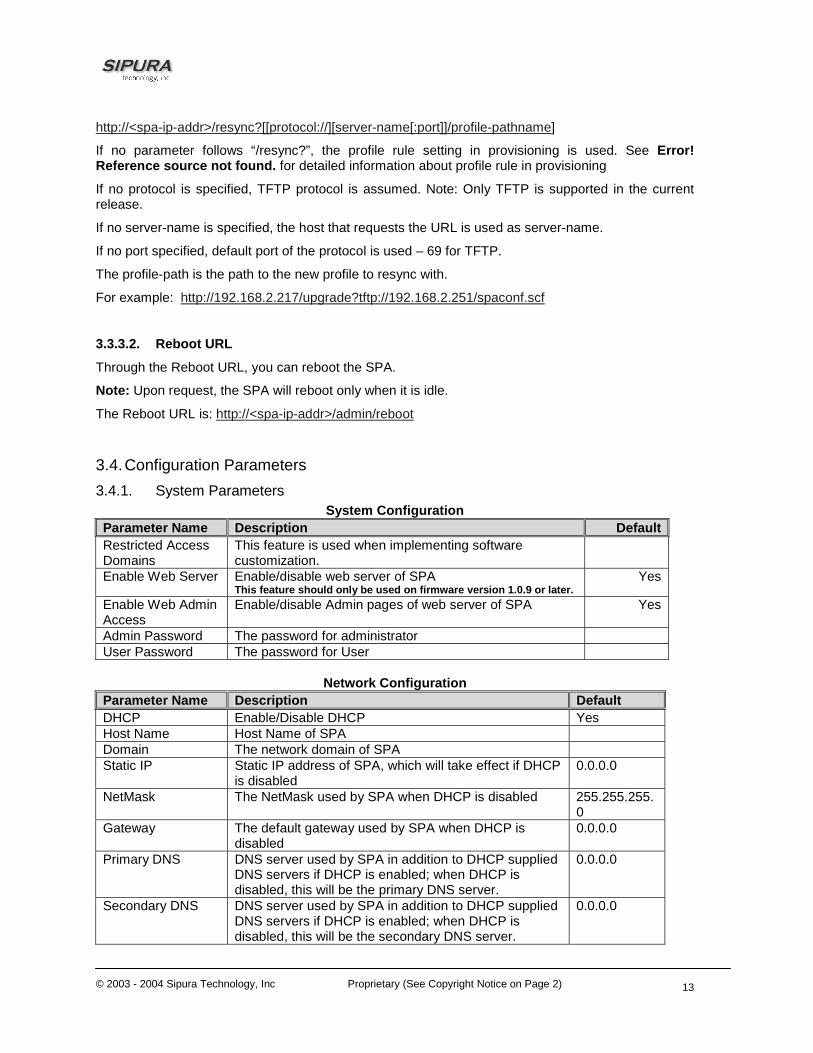
3.3.3.2. Reboot URL
Through the Reboot URL, you can reboot the SPA.
Note: Upon request, the SPA will reboot only when it is idle.
The Reboot URL is: http://<spa-ip-addr>/admin/reboot
3.4. Configuration Parameters 3.4.1. System Parameters
System Configuration Parameter Name Description DefaultRestricted Access Domains
This feature is used when implementing software customization.
Enable Web Server Enable/disable web server of SPA This feature should only be used on firmware version 1.0.9 or later.
Yes
Enable Web Admin Access
Enable/disable Admin pages of web server of SPA
Yes
Admin Password The password for administrator User Password The password for User
Network Configuration
Parameter Name Description Default DHCP Enable/Disable DHCP Yes Host Name Host Name of SPA Domain The network domain of SPA Static IP Static IP address of SPA, which will take effect if DHCP
is disabled 0.0.0.0
NetMask The NetMask used by SPA when DHCP is disabled 255.255.255.0
Gateway The default gateway used by SPA when DHCP is disabled
0.0.0.0
Primary DNS DNS server used by SPA in addition to DHCP supplied DNS servers if DHCP is enabled; when DHCP is disabled, this will be the primary DNS server.
0.0.0.0
Secondary DNS DNS server used by SPA in addition to DHCP supplied DNS servers if DHCP is enabled; when DHCP is disabled, this will be the secondary DNS server.
0.0.0.0

© 2003 - 2004 Sipura Technology, Inc Proprietary (See Copyright Notice on Page 2)
14
DNS Query Mode Do parallel or sequential DNS Query Parallel Syslog Server Specify the Syslog server name and port. This feature
specifies the server for logging SPA system information and critical events.
Debug Server The debug server name and port. This feature specifies the server for logging SPA debug information. The level of detailed output depends on the debug level parameter setting.
Debug Level The higher the debug level, the more debug information will be generated. Zero (0) means no debug information will be generated.
0
Primary NTP Server
IP address or name of primary NTP server.
Secondary NTP Server
IP address or name of secondary NTP server
Web Server Port TCP port through which the SPA web server will communicate
80
Notes: - Parallel DNS query mode: SPA will send the same request to all the DNS servers at the same
time when doing a DNS lookup, the first incoming reply will be accepted by SPA. - To log SIP messages, Debug Level must be set to at least 2. - If both Debug Server and Syslog Server are specified, _Syslog messages are also logged to the
Debug Server.
3.4.2. Provisioning Parameters Provisioning operations are gated by the Provision_Enable parameter.
Parameter Name Description Default Provision Enable yes Resync On Reset yes Resync Random Delay
2
Resync Periodic 3600 Resync Error Retry Delay
3600
Resync From SIP Yes Resync After Upgrade Attempt
Yes
Resync Trigger 1 Resync Trigger 2 Profile Rule /spa.cfg Profile Rule B Profile Rule C Profile Rule D Log Resync Request Msg
See provisioning discussion section
Log Resync Success Msg
See provisioning discussion

© 2003 - 2004 Sipura Technology, Inc Proprietary (See Copyright Notice on Page 2)
15
section Log Resync Failure Msg
See provisioning discussion section
GPP A thru GPP P empty GPP SA thru GPP SD empty
Note: In a customized SPA, the profile rule would point to a service provider’s server.
3.4.3. Upgrade Parameters Parameter Name Description Default Upgrade Enable Yes Upgrade Error Retry Delay
3600
Upgrade Rule empty Log Upgrade Request Msg
See provisioning discussion section
Log Upgrade Success Msg
See provisioning discussion section
Log Upgrade Failure Msg
See provisioning discussion section
Note: In a customized SPA, the upgrade rule would point to a service provider’s server.
3.4.4. Protocol Parameters Parameter Name Description Default Max Forward SIP Max-Forward value. Range: 1 – 255 70 Max Redirection Number of times to allow an INVITE to be
redirected by a 3xx response to avoid an infinite loop. Note: This parameter currently has no effect: there is no limit on number of redirection.
5
Max Auth Maximum number of times a request may be challenged (0-255)
2
SIP User Agent Name
User-Agent Header to be used by the unit in outbound requests. If empty, the header is not included.
Sipura/ $version
SIP Server Name Server Header to used by the unit in responses to inbound responses. If empty, the header is not included.
Sipura/ $version
SIP Accept Language
Accept-Language Header to be used by the unit. If empty, the header is not included.

© 2003 - 2004 Sipura Technology, Inc Proprietary (See Copyright Notice on Page 2)
16
Remove Last Reg Remove last registration before registering a new one if value is different one.
no
DTMF Relay MIME Type
This is the MIME Type to be used in a SIP INFO message used to signal DTMF event.
application/dtmf-relay
Hook Flash MIME Type
This is the MIME Type to be used in a SIP INFO message used to signal hook flash event.
application/hook-flash
Use Compact Header
If set to yes, the SPA will use compact SIP headers in outbound SIP messages. If set to no the SPA will use normal SIP headers.
no
SIP T1 RFC 3261 T1 value (RTT Estimate). Range: 0 – 64 sec
.5
SIP T2 RFC 3261 T2 value (Maximum retransmit interval for non-INVITE requests and INVITE responses). Range: 0 – 64 sec
4
SIP T4 RFC 3261 T4 value (Maximum duration a message will remain in the network). Range: 0 – 64 sec
5
SIP Timer B INVITE time out value. Range: 0 – 64 sec 32 SIP Timer F Non-INVITE time out value. Range: 0 – 64
sec 32
SIP Timer H INVITE final response time out value. Range: 0 – 64 sec
32
SIP Timer D ACK hang around time. Range: 0 – 64 sec 32 SIP Timer J Non-INVITE response hang around time.
Range: 0 – 64 sec 32
INVITE Expires INVITE request Expires header value in sec. 0 = do not include Expires header in INVITE. Range: 0 – (231 – 1)
180
ReINVITE Expires ReINVITE request Expires header value in sec. 0 = do not include Expires header in the request. Range: 0 – (231 – 1)
30
Reg Min Expires Minimum registration expiration time allowed from the proxy in the Expires header or as a Contact header parameter. If proxy returns something less this value, then the minimum value is used.
1
Reg Max Expires Maximum registration expiration time allowed from the proxy in the Min-Expires header. If value is larger than this, then the maximum value is used
7200
Reg Retry Intvl Interval to wait before the SPA retries registration again after encountering a failure condition during last registration
30
Reg Retry Long Interval
When Registration fails with a SIP response code that does no match <Retry Reg RSC>, the SPA will wait for the delay specified in this parameter before retrying. If this parameter is 0, the SPA will stop retrying. This value should be much larger than <Reg Retry Intvl> which should not be 0.
1200
SIT1 RSC1 SIP response status code to INVITE on which to play the SIT1 Tone

© 2003 - 2004 Sipura Technology, Inc Proprietary (See Copyright Notice on Page 2)
17
SIT2 RSC1 SIP response status code to INVITE on which to play the SIT2 Tone
SIT3 RSC1 SIP response status code to INVITE on which to play the SIT3 Tone
SIT4 RSC1 SIP response status code to INVITE on which to play the SIT4 Tone
Try Backup RSC SIP response status code on which to retry a backup server for the current request
Retry Reg RSC Interval to wait before the SPA retries registration again after encountering a failure condition during last registration
30
RTP Port Min2 Minimum port number for RTP transmission and reception
16384
RTP Port Max2 Maximum port number for RTP transmission and reception
16482
RTP Packet Size Packet size in sec. Valid values must be multiple of 0.01s. Range: 0.01 – 0.16
0.02
RTCP Tx Interval4 Controls the interval (sec) to send out RTCP sender report on an active connection. Range: 0 – 255 (s)
0
Notes: 1. Reorder or Busy Tone will be played by default for all unsuccessful response status code 2. <RTP Port Min> and <RTP Port Max> should define a range that contains at least 4 even number
ports, such as 100 – 106 3. If inbound SIP requests contain compact headers, SPA will reuse the same compact headers
when generating the response regardless the settings of the <Use Compact Header> parameter. If inbound SIP requests contain normal headers, SPA will substitute those headers with compact headers (if defined by RFC 261) if <Use Compact Header> parameter is set to “yes.”
4. During an active connection, the SPA can be programmed to send out compound RTCP packet on the connection. Each compound RTP packet except the last one contains a SR (Sender Report) and a SDES.(Source Description). The last RTCP packet contains an additional BYE packet. Each SR except the last one contains exactly 1 RR (Receiver Report); the last SR carries no RR. The SDES contains CNAME, NAME, and TOOL identifiers. The CNAME is set to <User ID>@<Proxy>, NAME is set to <Display Name> (or “Anonymous” if user blocks caller ID), and TOOL is set to the Verdor/Hardware-platform-software-version (such as Sipura/SPA2000-1.0.31(b)). The NTP timestamp used in the SR is a snapshot of the SPA’s local time, not the time reported by an NTP server. If the SPA receives a RR from the peer, it will attempt to compute the round trip delay and show it as the <Call Round Trip Delay> value (ms) in the Info section of SPA web page.
3.4.4.1. Dynamic Payload Types
Parameter Name Description Default NSE Dynamic Payload1,2 NSE dynamic payload type 100 AVT Dynamic Payload1,2 AVT dynamic payload type 101 G726r16 Dynamic Payload1,2 G726-16 dynamic payload type 98 G726r24 Dynamic Payload1,2 G726-24 dynamic payload type 97 G726r40 Dynamic Payload1,2 G726-40 dynamic payload type 96 G729b Dynamic Payload1,2 G729b dynamic payload type 99
Notes:
1. Valid range is 96 – 127

© 2003 - 2004 Sipura Technology, Inc Proprietary (See Copyright Notice on Page 2)
18
2. The configured dynamic payloads are used for outbound calls only where the SPA presents the SDP offer. For inbound calls with a SDP offer, SPA will follow the caller’s dynamic payload type assignments
3.4.4.2. SDP Audio Codec Names
Parameter Name Description Default NSE Codec Name NSE Codec name used in SDP NSE AVT Codec Name AVT Codec name used in SDP telephone-event G711a Codec Name G711a Codec name used in SDP PCMA G711u Codec Name G711u Codec name used in SDP PCMU G726r16 Codec Name G726-16 Codec name used in SDP G726-16 G726r24 Codec Name G726-24 Codec name used in SDP G726-24 G726r32 Codec Name G726-32 Codec name used in SDP G726-32 G726r40 Codec Name G726-40 Codec name used in SDP G726-40 G729a Codec Name G729a Codec name used in SDP G729a G729b Codec Name G729b Codec name used in SDP G729ab G723 Codec Name G723 Codec name used in SDP G723
Notes:
1. SPA uses the configured codec names in its outbound SDP
2. SPA ignores the codec names in incoming SDP for standard payload types (0 – 95).
3. For dynamic payload types, SPA identifies the codec by the configured codec names. Comparison is case-insensitive.
3.4.4.3. NAT Support Parameter Name Description Default Handle_VIA_received If set to “yes”, the SPA will process the “received”
parameter in the VIA header inserted by the server in a response to any one of its request. Else the parameter is ignored.
No
Handle_VIA_rport If set to “yes”, the SPA will process the “rport” parameter in the VIA header inserted by the server in a response to any one of its request. Else the parameter is ignored.
No
Insert VIA received Insert received parameter in VIA header in SIP responses if received from IP and VIA sent-by IP differ
No
Insert VIA rport Insert rport parameter in VIA header in SIP responses if received-from port and VIA sent-by port differ
No
Substitute VIA addr Use nat-mapped IP:port values in VIA header No Send Resp To Src Port Send response to the request source port instead of
the VIA sent-by port No
STUN Server STUN server to contact for NAT mapping discovery STUN Enable Enable the use of STUN to discover NAT mapping No STUN Test Enable If enabled with <STUN Enable> = “yes” and a valid
<STUN Server>, the SPA will perform a NAT type discovery operation when first power on by contacting the configured STUN server. The result of the discovery will be reported in a Warning
No

© 2003 - 2004 Sipura Technology, Inc Proprietary (See Copyright Notice on Page 2)
19
header in all subsequent REGISTER requests – “Warning: 399 spa <stun type>”, where <stun type> is one of the following: "Unknown NAT Type", "STUN Server Not Reachable", "STUN Server Not Responding", "Open Internet Detected", "Symmetric Firewall Detected", "Full Cone NAT Detected", "Restricted Cone NAT Detected", "Symmetric NAT Detected"; If the SPA detects Symmetric Nat or Symmetric Firewall, Nat Mapping will be disabled (that is, no substitution of IP address and port with external IP address an nat-mapped port)
Ext IP External IP address to substitute for the actual IP address of the unit in all outgoing SIP messages. If “0.0.0.0” is specified, no IP address substitution is performed.
0.0.0.0
Ext RTP Port Min External port mapping of <RTP Port Min>. If this value is non-zero, the RTP port number in all outgoing SIP messages is substituted by the corresponding port value in the external RTP port range.
0
NAT Keep Alive Intvl Interval between sending NAT-mapping keep alive message in sec
15
Notes:
3.4.5. Line 1 and Line 2 Parameters Per line parameter tags must be appended with [1] or [2] (corresponding to lines 1 or 2) in the configuration profile. It is omitted below for readability.
3.4.5.1. User Account Information Parameter Name Description Default Line Enable Enable this line for service Yes MOH Server2 The User ID or URL of the auto-answering SAS to
contact for MOH services. Examples: 5000, [email protected], 66.12.123.15:5061. Note: When only a user-id is given, the current proxy or outbound proxy will be contacted as in the making of a regular outbound call. MOH is disabled if this parameter is not specified (empty).
Empty
SIP Port SIP message listening port and transmission port 5060 Ext SIP Port External port to substitute for the actual SIP port of
the unit in all outgoing SIP messages. If “0” is specified, no SIP port substitution is performed.
0
SIP TOS/DiffServ Value
TOS/DiffServ field value in UDP IP Packets carrying a SIP Message
0x68
RTP TOS/DiffServ Value
TOS/DiffServ field value in UDP IP Packets carrying a RTP data
0xb8

© 2003 - 2004 Sipura Technology, Inc Proprietary (See Copyright Notice on Page 2)
20
SAS Enable3 Enables the FXS Line to act as a Streaming Audio Source (SAS). If enabled, the line cannot be used for making outgoing calls. Instead, it auto-answers incoming calls and streams audio RTP packets to the calling party.
No
SAS DLG Refresh Intvl3
If non-zero, this is the interval at which SAS sends out session refresh (SIP re-INVITE) messages to detect if connection to the caller is still up. If the caller does not respond to refresh message, SPA will terminate this call with a SIP BYE message. The default = 0 (Session refresh disabled) Range = 0-255 (s)
0
SAS Inbound RTP Sink3
The purpose of this parameter is to work around devices that do not play inbound RTP if the SAS line declares itself as a “sendonly” device and tells the client not to stream out audio. This parameter is a FQDN or IP address of a RTP sink to be used by the SPA SAS line in the SDP of its 200 response to inbound INVITE from a client. It will appear in the c = line and the port number and, if specified, in the m = line of the SDP. If this value is not specified or equal to 0, then c = 0.0.0.0 and a=sendonly will be used in the SDP to tell the SAS client to not to send any RTP to this SAS line. If a non-zero value is specified, then a=sendrecv and the SAS client will stream audio to the given address. Special case: If the value is $IP, then the SAS line’s own IP address is used in the c = line and a=sendrecv. In that case the SAS client will stream RTP packets to the SAS line. The default value is [empty].
NAT Mapping Enable Enable the use of externally mapped of IP address and SIP/RTP ports in SIP messages. The mapping may be discovered by any of the supported methods.
No
NAT Keep Alive Enable
If set to “yes”, the configured <NAT Keep Alive Msg> is sent periodically every <NAT Keep Alive Intvl> seconds.
No
NAT Keep Alive Msg Contents of the keep-alive message to be sent to a given destination periodically to maintain the current NAT-mapping. It could be an empty string. If value is $NOTIFY, a NOTIFY message is sent as keep alive. If value is $REGISTER, a REGISTER message w/o Contact is sent.
$NOTIFY
NAT Keep Alive Dest Destination to send NAT keep alive messages to. If value is $PROXY, it will be sent to the current proxy or outbound proxy
$PROXY
SIP Debug Option None, 1-line, full, exclude OPTIONS, exclude REGISTER, exclude NOTIFY, …
none
Network Jitter Level 4 settings are available: very high, high, medium, low. This parameter affects how jitter buffer size is adjusted in the SPA. Jitter buffer size is adjusted dynamically. The minimum jitter buffer size is 30 ms or (10 ms + current RTP frame size), which ever is larger, for all jitter level settings. But the
High

© 2003 - 2004 Sipura Technology, Inc Proprietary (See Copyright Notice on Page 2)
21
starting jitter buffer size value is larger for higher jitter levels. This parameter controls the rate at which to adjust the jitter buffer size to reach the minimum. If the jitter level is set to high, then the rate of buffer size decrement is slower (more conservative), else faster (more aggressive).
SIP 100REL Enable Enable the support or the 100rel SIP extension for reliable transmission of provisional responses (18x) and the use of PRACK requests.
No
Blind Attn-Xfer Enable
If enabled, the SPA performs an attended transfer operation by terminating the current call leg, and blind transferring the other call leg. If disabled, the SPA performs an attended transfer by referring the other call leg to the current call leg while maintaining both call legs.
No
Proxy SIP Proxy Server for all outbound requests Use Outbound Proxy Enable the use of <Outbound Proxy>. If set to “no”,
<Outbound Proxy> and <Use OB Proxy in Dialog) is ignored.
No
Outbound Proxy SIP Outbound Proxy Server where all outbound requests are sent as the first hop.
No
Use OB Proxy In Dialog
Whether to forcer SIP requests to be sent to the outbound proxy within a dialog. Ignored if <Use Outbound Proxy> is “no” or <Outbound Proxy> is empty
Yes
Register Enable periodic registration with the <Proxy>. This parameter is ignored if <Proxy> is not specified.
Yes
Make Call Without Reg
Allow making outbound calls without successful (dynamic) registration by the unit. If “No”, dial tone will not play unless registration is successful
No
Ans Call Without Reg Allow answering inbound calls without successful (dynamic) registration by the unit
No
Register Expires1 Expires value in sec in a REGISTER request. SPA will periodically renew registration shortly before the current registration expired. This parameter is ignored if <Register> is “no”. Range: 0 – (231 – 1) sec
3600
Use DNS SRV Whether to use DNS SRV lookup for Proxy and Outbound Proxy
No
DNS SRV Auto Prefix If enabled, the SPA will automatically prepend the Proxy or Outbound Proxy name with _sip._udp when performing a DNS SRV lookup on that name
No
Proxy Fallback Intvl This parameter sets the delay (sec) after which the SPA will retry from the highest priority proxy (or outbound proxy) servers after it has failed over to a lower priority server. This parameter is useful only if the primary and backup proxy server list is provided to the SPA via DNS SRV record lookup on the server name. (Using multiple DNS A record per server name does not allow the notion of priority and so all hosts will be considered at the same priority and the SPA will not attempt to fall back after a fail over)
3600
Display Name Subscriber’s display name to appear in caller-id

© 2003 - 2004 Sipura Technology, Inc Proprietary (See Copyright Notice on Page 2)
22
User ID Subscriber’s user-id. Usually a E.164 number Password Subscriber’s a/c password Auth ID Subscriber’s authentication ID Use Auth ID If set to “yes”, the pair <Auth ID> and <Password>
are used for SIP authentication. Else the pair <User ID> and <Password> are used.
No
Mini Certificate Base64 encoded of Mini-Certificate concatenated with the 1024-bit public key of the CA signing the MC of all subscribers in the group.
Empty
SRTP Private Key Base64 encoded of the 512-bit private key per subscriber for establishment of a secure call.
Empty
Notes:
1. If proxy responded to REGISTER with a smaller Expires value, the SPA will renew registration based on this smaller value instead of the configured value. If registration failed with an “Expires too brief” error response, the SPA will retry with the value given in the Min-Expires header in the error response.
2. MOH Notes:
• The remote party must indicate that it can receive audio while holding MOH to work. That is the SIP 2xx response from the remote party in reply to the re-INVITE from the SPA to put the call on hold must have the SDP indicate a sendrecv or recvonly attribute and the remote destination address and port must not be 0
3. SAS Notes:
• Either or both of lines 1 and 2 can be configured as an SAS server.
• Each server can maintain up to 5 simultaneous calls. If the second line on the SPA is disabled, then the SAS line can maintain up to 10 simultaneous calls. Further incoming calls will receive a busy signal (SIP 486 Response).
• The streaming audio source must be off-hook for the streaming to occur. Otherwise incoming calls will get a error response (SIP 503 Response). The SAS line will not ring for incoming calls even if the attached equipment is on-hook
• If no calls are in session, battery is removed from tip-and-ring of the FXS port. Some audio source devices have an LED to indicate the battery status. This can be used as a visual indication whether any audio streaming is in progress.
• IVR can still be used on an SAS line, but the user needs to follow some simple steps: a) Connect a phone to the port and make sure the phone is on-hook, b) power on the SPA and c) pick up handset and press * * * * to invoke IVR in the usual way. The idea behind this is that if the SPA boots up and finds that the SAS line is on-hook, it will not remove battery from the line so that IVR may be used. But if the SPA boots up and finds that the SAS line is off-hook, it will remove battery from the line since no audio session is in progress.
• Set up the Proxy and Subscriber Information for the SAS Line as you normally would with a regular user account.
• Call Forwarding, Call Screening, Call Blocking, DND, and Caller-ID Delivery features are not available on an SAS line.
3.4.5.2. Supplementary Services Enablement

© 2003 - 2004 Sipura Technology, Inc Proprietary (See Copyright Notice on Page 2)
23
The SPA provides native support of a large set of enhanced or supplementary services. All of these services are optional. The parameters listed in the following table are used to enable or disable a specific supplementary service. A supplementary service should be disabled if a) the user has not subscribed for it, or b) the Service Provider intends to support similar service using other means than relying on the SPA.
Parameter Name Description Default Call Waiting Serv Enable Call Waiting Service Yes Block CID Serv Enable Block Caller ID Service Yes Block ANC Serv Enable Block Anonymous Calls Service Yes Dist Ring Serv Enable Distinctive Ringing Service Yes Cfwd All Serv Enable Call Forward All Service Yes Cfwd Busy Serv Enable Call Forward Busy Service Yes
Cfwd No Ans Serv Enable Call Forward No Answer Service Yes Cfwd Sel Serv Enable Call Forward Selective Service Yes Cfwd Last Serv Enable Forward Last Call Service Yes Block Last Serv Enable Block Last Call Service Yes Accept Last Serv Enable Accept Last Call Service Yes DND Serv Enable Do Not Disturb Service Yes CID_Serv Enable Caller ID Service Yes CWCID Serv Enable Call Waiting Caller ID Service Yes Call Return Serv Enable Call Return Service Yes Call Back Serv Enable Call Back Service Yes Three Way Call Serv1 Enable Three Way Calling Service Yes Three Way Conf Serv1,2
Enable Three Way Conference Service Yes
Attn Transfer Serv1,2 Enable Attended Call Transfer Service Yes Unattn Transfer Serv Enable Unattended (Blind) Call Transfer
Service Yes
MWI Serv3 Enable MWI Service Yes VMWI Serv Enable VMWI Service (FSK) Yes Speed Dial Serv Enable Speed Dial Service Yes Secure Call Serv Enable Secure Call Service Yes Referral Serv Enable Referral Service. See <Referral
Services Codes> for more details Yes
Feature Dial Serv Enable Feature Dial Service. See <Feature Dial Services Codes> for more details
Yes
Notes:
1. Three Way Calling is required for Three Way Conference and Attended Transfer.
2. Three Way Conference is required for Attended Transfer.
3. MWI is available only if a Voice Mail Service is set-up in the deployment.
3.4.5.3. Audio Settings

© 2003 - 2004 Sipura Technology, Inc Proprietary (See Copyright Notice on Page 2)
24
Parameter Name Description Default Preferred Codec Select a preferred codec for all calls. However, the
actual codec used in a call still depends on the outcome of the codec negotiation protocol.G711u, G711a, G726-16, G726-24, G726-32, G726-40, G729a, G723
G711u
Use Pref Codec Only Only use the preferred codec for all calls. The call will fail if the far end does not support this codec.
No
LBR Codec Enable *** This parameter has been removed. *** Silence Supp Enable Enable silence suppression so that silent audio
frames are not transmitted No
Echo Canc Enable Enable the use of echo canceller Yes Echo Canc Adapt Enable
Enable echo canceller to adapt Yes
Echo Supp Enable Enable the use of echo suppressor. If <Echo Canc Enable> is “no”, this parameter is ignored
Yes
G729a Enable1 Enable the use of G729a codec at 8 kbps. Yes G723 Enable1 Enable the use of G723 codec at 6.3 kbps Yes G726-16 Enable1 Enable the use of G726 codec at 16 kbps Yes G726-24 Enable1 Enable the use of G726 codec at 24 kbps Yes G726-32 Enable1 Enable the use of G726 codec at 32 kbps Yes G726-40 Enable1 Enable the use of G726 codec at 40 kbps Yes FAX Passthru Enable *** This parameter has been removed. *** Yes FAX CED Detect Enable Enable detection of FAX tone. Yes FAX CNG Detect Enable
Yes
FAX Passthru Codec Codec to use for fax passthru G711u FAX Codec Symmetric Force unit to use symmetric codec during FAX
passthru Yes
FAX Passthru Method Choices: None / NSE / ReINVITE NSE FAX Process NSE Yes DTMF Tx Method Method to transmit DTMF signals to the far end:
Inband = Send DTMF using the audio path; INFO = Use the SIP INFO method, AVT = Send DTMF as AVT events; Auto = Use Inband or AVT based on outcome of codec negotiation
Auto
Hook Flash Tx Method Select the method to signal Hook Flash events: • None: do not signal hook flash events • AVT: use RFC2833 AVT (event=16) • INFO: use SIP INFO method with the single line “signal = hf” in the message body. The MIME type for this message body is taken from the <Hook Flash MIME Type> paramter
None
Release Unused Codec Yes
Notes:
1. A codec resource is considered as allocated if it has been included in the SDP codec list of an active call, even though it eventually may not be the one chosen for the connection. So, if the G.729a codec is enabled and included in the codec list, that resource is tied up until the end of the call whether or not the call actually uses G.729a. If the G729a resource is already allocated and since only one G.729a resource is allowed per SPA, no other low-bit-rate codec may be allocated for subsequent calls; the only choices are G711a and G711u. On the other hand, two G.723.1/G.726
© 2003 - 2004 Sipura Technology, Inc Proprietary (See Copyright Notice on Page 2)
25
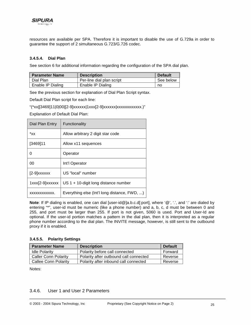
resources are available per SPA. Therefore it is important to disable the use of G.729a in order to guarantee the support of 2 simultaneous G.723/G.726 codec.
3.4.5.4. Dial Plan
See section 6 for additional information regarding the configuration of the SPA dial plan.
Parameter Name Description Default Dial Plan Per-line dial plan script See below Enable IP Dialing Enable IP Dialing no
See the previous section for explanation of Dial Plan Script syntax.
Default Dial Plan script for each line:
“(*xx|[3469]11|0|00|[2-9]xxxxxx|1xxx[2-9]xxxxxx|xxxxxxxxxxxx.)”
Explanation of Default Dial Plan:
Dial Plan Entry Functionality
*xx Allow arbitrary 2 digit star code
[3469]11 Allow x11 sequences
0 Operator
00 Int’l Operator
[2-9]xxxxxx US "local" number
1xxx[2-9]xxxxxx US 1 + 10-digit long distance number
xxxxxxxxxxxx. Everything else (Int’l long distance, FWD, ...)
Note: If IP dialing is enabled, one can dial [user-id@]a.b.c.d[:port], where ‘@’, ‘.’, and ‘:’ are dialed by entering “*”, user-id must be numeric (like a phone number) and a, b, c, d must be between 0 and 255, and port must be larger than 255. If port is not given, 5060 is used. Port and User-Id are optional. If the user-id portion matches a pattern in the dial plan, then it is interpreted as a regular phone number according to the dial plan. The INVITE message, however, is still sent to the outbound proxy if it is enabled.
3.4.5.5. Polarity Settings
Parameter Name Description Default Idle Polarity Polarity before call connected Forward Caller Conn Polarity Polarity after outbound call connected Reverse Callee Conn Polarity Polarity after inbound call connected Reverse
Notes:
3.4.6. User 1 and User 2 Parameters

© 2003 - 2004 Sipura Technology, Inc Proprietary (See Copyright Notice on Page 2)
26
User 1/2 refers to the subscriber of Line 1/2. When a call is made from Line 1/2, SPA shall use the user and line settings for that Line; there is no user login support in SPA v1.0. Per user parameter tags must be appended with [1] or [2] (corresponding to line 1 or 2) in the configuration profile. It is omitted below for readability. 3.4.6.1. Call Forward And Selective Call Forward/Blocking Settings
Parameter Name Description Default Cfwd All Dest Forward number for Call Forward All Service Cfwd Busy Dest Forward number for Call Forward Busy Service Cfwd No Ans Dest Forward number for Call Forward No Answer Service Cfwd No Ans Delay Delay in sec before Call Forward No Answer triggers 20 Cfwd Sel1 Caller Caller number pattern to trigger Call Forward Selective 1 Cfwd Sel2 Caller Caller number pattern to trigger Call Forward Selective 2 Cfwd Sel3 Caller Caller number pattern to trigger Call Forward Selective 3 Cfwd Sel4 Caller Caller number pattern to trigger Call Forward Selective 4 Cfwd Sel5 Caller Caller number pattern to trigger Call Forward Selective 5 Cfwd Sel6 Caller Caller number pattern to trigger Call Forward Selective 6 Cfwd Sel7 Caller Caller number pattern to trigger Call Forward Selective 7 Cfwd Sel8 Caller Caller number pattern to trigger Call Forward Selective 8 Cfwd Sel1 Dest Forward number for Call Forward Selective 1 Cfwd Sel2 Dest Forward number for Call Forward Selective 2 Cfwd Sel3 Dest Forward number for Call Forward Selective 3 Cfwd Sel4 Dest Forward number for Call Forward Selective 4 Cfwd Sel5 Dest Forward number for Call Forward Selective 5 Cfwd Sel6 Dest Forward number for Call Forward Selective 6 Cfwd Sel7 Dest Forward number for Call Forward Selective 7 Cfwd Sel8 Dest Forward number for Call Forward Selective 8 Block Last Caller ID of caller blocked via the “Block Last Caller” service Accept Last Caller ID of caller accepted via the “Accept Last Caller” service Cfwd Last Caller The Caller number that is actively forwarded to <Cfwd
Last Dest> by using the Call Forward Last activation code
Cfwd Last Dest Forward number for the <Cfwd Last Caller> 3.4.6.2. Speed Dial Settings
Parameter Name Description Default Speed Dial 2 Target phone number (or URL) assigned to speed dial “2” Speed Dial 3 Target phone number (or URL) assigned to speed dial “3” Speed Dial 4 Target phone number (or URL) assigned to speed dial “4” Speed Dial 5 Target phone number (or URL) assigned to speed dial “5” Speed Dial 6 Target phone number (or URL) assigned to speed dial “6” Speed Dial 7 Target phone number (or URL) assigned to speed dial “7” Speed Dial 8 Target phone number (or URL) assigned to speed dial “8” Speed Dial 9 Target phone number (or URL) assigned to speed dial “9”
3.4.6.3. Supplementary Service Settings

© 2003 - 2004 Sipura Technology, Inc Proprietary (See Copyright Notice on Page 2)
27
Parameter Name Description Default CW Setting Call Waiting on/off for all calls Yes Block CID Setting Block Caller ID on/off for all calls No Block ANC Setting Block Anonymous Calls on or off No DND Setting DND on or off No CID Setting Caller ID Generation on or off Yes CWCID Setting Call Waiting Caller ID Generation on or off Yes Dist Ring Setting Distinctive Ring on or off Yes Secure Call Setting If yes, all outbound calls are secure calls by default No
3.4.6.4. Distinctive Ring and Ring Settings
Parameter Name Description Default Ring 1 Caller Caller number pattern to play Distinctive Ring/CWT 1 Ring 2 Caller Caller number pattern to play Distinctive Ring/CWT 2 Ring 3 Caller Caller number pattern to play Distinctive Ring/CWT 3 Ring 4 Caller Caller number pattern to play Distinctive Ring/CWT 4 Ring 5 Caller Caller number pattern to play Distinctive Ring/CWT 5 Ring 6 Caller Caller number pattern to play Distinctive Ring/CWT 6 Ring 7 Caller Caller number pattern to play Distinctive Ring/CWT 7 Ring 8 Caller Caller number pattern to play Distinctive Ring/CWT 8 Default Ring Default ringing pattern, 1 – 8, for all callers 1 Default CWT Default CWT pattern, 1 – 8, for all callers 1 Hold Reminder Ring Ring pattern for reminder of a holding call when the
phone is on-hook None
Call Back Ring Ring pattern for call back notification None Cfwd Ring Splash Len2
Duration of ring splash when a call is forwarded (0 – 10.0s)
0
Cblk Ring Splash Len2
Duration of ring splash when a call is blocked (0 – 10.0s)
0
VMWI Ring Splash Len
Duration of ring splash when new messages arrive before the VMWI signal is applied (0 – 10.0s)
.5
VMWI Ring Policy The parameter controls when a ring splash is played when a the VM server sends a SIP NOTIFY message to the SPA indicating the status of the subscriber’s mail box. 3 settings are available: New VM Available – ring as long as there is 1 or more unread voice mail New VM Becomes Available – ring when the number of unread voice mail changes from 0 to non-zero New VM Arrives – ring when the number of unread voice mail increases
New VM Available
Ring On No New VM If enabled, the SPA will play a ring splash when the VM server sends SIP NOTIFY message to the SPA indicating that there are no more unread voice mails. Some equipment requires a short ring to precede the FSK signal to turn off VMWI lamp
No
Notes: 1. Caller number patterns are matched from Ring 1 to Ring 8. The first match (not the closest
match) will be used for alerting the subscriber. 2. Feature not yet available.

© 2003 - 2004 Sipura Technology, Inc Proprietary (See Copyright Notice on Page 2)
28
3.4.7. Regional Parameters 3.4.7.1. Call Progress Tones
Parameter Name Description Default Dial Tone1 Played when prompting the user to enter a
phone number 350@-19,440@-19;10(*/0/1+2)
Second Dial Tone An alternative to <Dial Tone> when user tries to dial a 3-way call
420@-19,520@-19;10(*/0/1+2)
Outside Dial Tone1 An alternative to <Dial Tone> usually used to prompt the user to enter an external phone number (versus an internal extension). This is triggered by a “,” character encountered in the dial plan.
420@-16;10(*/0/1)
Prompt Tone1 Played when prompting the user to enter a call forward phone number
520@-19,620@-19;10(*/0/1+2)
Busy Tone Played when a 486 RSC is received for an outbound call
480@-19,620@-19;10(.5/.5/1+2)
Reorder Tone1,2 Played when an outbound call has failed or after the far end hangs up during an established call
480@-19,620@-19;10(.25/.25/1+2)
Off Hook Warning Tone2
Played when the subscriber does not place the handset on the cradle properly
480@-10,620@0;10(.125/.125/1+2)
Ring Back Tone Played for an outbound call when the far end is ringing
440@-19,480@-19;*(2/4/1+2)
Confirm Tone This should be a brief tone to notify the user that the last input value has been accepted.
600@-16;1(.25/.25/1)"
SIT1 Tone An alternative to <Reorder Tone> played when an error occurs while making an outbound call. The RSC to trigger this tone is configurable (see Section ???)
985@-16,1428@-16,1777@-16;20(.380/0/1,.380/0/2,.380/0/3,0/4/0)
SIT2 Tone See <SIT1 Tone> 914@-16,1371@-16,1777@-16;20(.274/0/1,.274/0/2,.380/0/3,0/4/0)
SIT3 Tone See <SIT1 Tone> 914@-16,1371@-16,1777@-16;20(.380/0/1,.380/0/2,.380/0/3,0/4/0)
SIT4 Tone See <SIT 1 Tone> 985@-16,1371@-16,1777@-16;20(.380/0/1,.274/0/2,.380/0/3,0/4/0)
MWI Dial Tone1 This tone is played instead of <Dial Tone> when there are unheard messages in the subscriber’s mail box
350@-19,440@-19;2(.1/.1/1+2);10(*/0/1+2)
Cfwd Dial Tone Special dial tone played when call forward all is activated
350@-19,440@-19;2(.2/.2/1+2);10(*/0/1+2)

© 2003 - 2004 Sipura Technology, Inc Proprietary (See Copyright Notice on Page 2)
29
Holding Tone Indicate to the local user that the far end has placed the call on hold
600@-16;*(.1/.1/1,.1/.1/1,.1/9.5/1)
Conference Tone Plays to all parties when a 3-way conference is in progress
350@-16;30(.1/.1/1,.1/9.7/1)
Secure Call Indication Tone
This tone is played when a call is successfully switched to secure mode. It should be played only for a short while (< 30s) and at a reduced level (< -19 dBm) so that it will not interfere with the conversation.
397@-19,507@-19;15(0/2/0,.2/.1/1,.1/2.1/2)
Notes: 1. Reorder Tone is played automatically when <Dial Tone> or any of its alternatives times out 2. Off Hook Warning Tone is played when Reorder Tone times out 3.4.7.2. Ring and CWT Cadence
Parameter Name Description Default Ring1 Cadence Cadence script for distinctive ring 1 60(2/4)" Ring2 Cadence Cadence script for distinctive ring 2 60(.3/.2,
1/.2,.3/4)" Ring3 Cadence Cadence script for distinctive ring 3 60(.8/.4,.8/4) Ring4 Cadence Cadence script for distinctive ring 4 60(.4/.2,.3/.2,.8/4) Ring5 Cadence Cadence script for distinctive ring 5 60(.4/.2,.3/.2,.8/4) Ring6 Cadence Cadence script for distinctive ring 6 60(.4/.2,.3/.2,.8/4) Ring7 Cadence Cadence script for distinctive ring 7 60(.4/.2,.3/.2,.8/4) Ring8 Cadence Cadence script for distinctive ring 8 60(.4/.2,.3/.2,.8/4) CWT 1 Cadence Cadence script for distinctive CWT 1 30(.3/9.7) CWT2 Cadence Cadence script for distinctive CWT 2 30(.1/.1, .1/9.7)" CWT3 Cadence Cadence script for distinctive CWT 3 30(.1/.1, .1/.1,
.1/9.5) CWT4 Cadence Cadence script for distinctive CWT 4 30(.1/.1, .3/.1,
.1/9.3) CWT5 Cadence Cadence script for distinctive CWT 5 30(.3/.1,.1/.1,.3/9.
1) CWT6 Cadence Cadence script for distinctive CWT 6 30(.1/.1, .3/.1,
.1/9.3) CWT7 Cadence Cadence script for distinctive CWT 7 30(.1/.1, .3/.1,
.1/9.3) CWT8 Cadence Cadence script for distinctive CWT 8 2.3(..3/2) Ring1 Name Name in an INVITE’s Alert-Info Header to pick
distinctive ring/CWT 1 for the inbound call Bellcore-r1
Ring2 Name Name in an INVITE’s Alert-Info Header to pick distinctive ring/CWT 2 for the inbound call
Bellcore-r2
Ring3 Name Name in an INVITE’s Alert-Info Header to pick distinctive ring/CWT 3 for the inbound call
Bellcore-r3
Ring4 Name Name in an INVITE’s Alert-Info Header to pick distinctive ring/CWT 4 for the inbound call
Bellcore-r4
Ring5 Name Name in an INVITE’s Alert-Info Header to pick distinctive ring/CWT 5 for the inbound call
Bellcore-r5

© 2003 - 2004 Sipura Technology, Inc Proprietary (See Copyright Notice on Page 2)
30
Ring6 Name Name in an INVITE’s Alert-Info Header to pick distinctive ring/CWT 6 for the inbound call
Bellcore-r6
Ring7 Name Name in an INVITE’s Alert-Info Header to pick distinctive ring/CWT 7 for the inbound call
Bellcore-r7
Ring8 Name Name in an INVITE’s Alert-Info Header to pick distinctive ring/CWT 8 for the inbound call
Bellcore-r8
Ring Waveform Waveform for the ringing signal Sinusoid Ring Frequency Frequency of the ringing signal. Valid values
are 10 – 100 (Hz) 25
Ring Voltage Ringing voltage. 60-90 (V) 70 CWT Frequency Frequency script of the call waiting tone. All
distinctive CWT is based on this tone. 440@-10
Notes: 3.4.7.3. Control Timer Values (sec)
Parameter Name Description Default Hook Flash Timer Min Minimum on-hook time before off-hook to
qualify as hook-flash. Less than this the on-hook event is ignored. Range: 0.1 – 0.4 sec
0.1
Hook Flash Timer Max Maximum on-hook time before off-hook to qualify as hook-flash. More than this the on-hook event is treated as on-hook (no hook-flash event). Range: 0.4 – 1.6 sec
0.9
Callee On Hook Delay The phone must be on-hook for at this time in sec before the SPA will tear down the current inbound call. It does not apply to outbound calls. Range: 0 – 255 sec
0
Reorder Delay Delay after far end hangs up before reorder tone is played. 0 = plays immediately, inf = never plays. Range: 0 – 255 sec
5
Call Back Expires Expiration time in sec of a call back activation. Ragne: 0 – 65535 sec
1800
Call Back Retry Intvl Call back retry interval in sec. Range: 0 – 255 sec
30
Call Back Delay Delay after receiving the first SIP 18x response before declaring the remote end is ringing. If a busy response is received during this time, the SPA still considers the call as failed and keeps on retrying.
0.5
VMWI Refresh Intvl Interval between VMWI refresh to the CPE 0.5 Interdigit Long Timer2 Long timeout between entering digits when
dialing. Range: 0 – 64 sec 10
Interdigit Short Timer2 Short timeout between entering digits when dialing. Range: 0 – 64 sec
3
CPC Delay3,4 Delay in seconds after caller hangs up when the SPA will start removing the tip-and-ring voltage to the attached equipment of the called party. Range= 0 to 255(s) Resolution = 1 (s)
2
CPC Duration3,4 Duration in seconds for which the tip-to-ring 0 (CPC

© 2003 - 2004 Sipura Technology, Inc Proprietary (See Copyright Notice on Page 2)
31
voltage is removed after the caller hangs up. After that tip-to-ring voltage is restored and dial tone will apply if the attached equipment is still off hook. CPC is disabled if this value is set to 0. Range= 0 to 1.000 (s) Resolution = 0.001 (s)
disabled)
Notes: 1. The Call Progress Tones and DTMF playback level are not affected by the <FXS Port Output
Gain>. 2. The interdigit timer values are used as defaults when dialing. The Interdigit_Long_Timer is used
after any one digit, if all valid matching sequences in the dial plan are incomplete as dialed. The Interdigit_Short_Timer is used after any one digit, if at least one matching sequence is complete as dialed, but more dialed digits would match other as yet incomplete sequences.
3. SPA has had polarity reversal feature since release 1.0 which can be applied to both the caller and the callee end. This feature is generally used for answer supervision on the caller side to signal to the attached equipment when the call has been connected (remote end has answered) or disconnected (remote end has hung up). This feature should be disabled for the called party (ie by using the same polarity for connected and idle state) and the CPC feature should be used instead.
4. Without CPC enabled, reorder tone will is played after a configurable delay. If CPC is enabled, dial tone will be played when tip-to-ring voltage is restored.
3.4.7.4. Vertical Service Code Assignment
Parameter Name Description Default Call Return Code Call the last caller. *69 Blind Transfer Code Blind transfer current call to the target
specified after the activation code *98
Cfwd All Act Code Forward all calls to the target specified after the activation code
*72
Cfwd All Deact Code Cancel call forward all *73 Cfwd Busy Act Code Forward busy calls to the target specified
after the activation code *90
Cfwd Busy Deact Code Cancel call forward busy *91 Cfwd No Ans Act Code Forward no-answer calls to the target
specified after the activation code *92
Cfwd No Ans Deact Code Cancel call forward no-answer *93 Cfwd Last Act Code Forward the last inbound or outbound calls
to the target specified after the activation code
*63
Cfwd Last Deact Code Cancel call forward last *83 Block Last Act Code Block the last inbound call *60 Block Last Deact Code Cancel blocking of the last inbound call *80 Accept Last Act Code Accept the last outbound call. Let it ring
through when DND or Call Forward All is in effect
*64
Accept Last Deact Code Cancel Accept Last *84 Call Back Act Code Callback when the last outbound call is not
busy *66
Call Back Deact Code Cancel callback *86 CW_Act_Code Enable Call Waiting on all calls *56 CW_Deact_Code Disable Call Waiting on all calls *57

© 2003 - 2004 Sipura Technology, Inc Proprietary (See Copyright Notice on Page 2)
32
CW_Per_Call_Act_Code Enable Call Waiting for the next call *71 CW_Per_Call_Deact_Code Disable Call Waiting for the next call *70 Block_CID_Act_Code Block CID on all outbound calls *67 Block_CID_Deact_Code Unblock CID on all outbound calls *66 Block_CID_Per_Call_Act_Code Block CID on the next outbound call *81 Blcok_CID_Per_Call_Deact_Code Unblock CID on the next inbound call *82 Block_ANC_Act_Code Block all anonymous calls *77 Block_ANC_Deact_Code Unblock all anonymous calls *87 DND_Act_Code Enable Do Not Disturb *78 DND_Deact_Code Disable Do Not Disturb *79 CID_Act_Code Enable Caller-ID Generation *65 CID_Deact_Code Disable Call-ID Generation *85 CWCID_Act_Code Enable Call Waiting Caller-ID generation *25 CWCID_Deact_Code Disable Call Waiting Caller-ID generation *45 Dist_Ring_Act_Code Enable Distinctive Ringing *61 Dist_Ring_Deact_Code Disable Distinctive Ringing *81 Speed Dial Act Code Assign a speed dial number *74 Secure All Call Act Code Make all outbound calls secure *16 Secure No Call Act Code Make all outbound calls not secure *17 Secure One Call Act Code Make the next outbound call secure. This
operation is redundant if all outbound calls are secure by default.
*18
Secure One Call Deact Code Make the next outbound call not secure. This operation is redundant if all outbound calls are not secure by default.
*19
Referral Services Codes One or more *code can be configured into this parameter, such as *98, or *97|*98|*123, etc. Max total length is 79 chars. This parameter applies when the user places the current call on hold (by Hook Flash) and is listening to 2nd dial tone. Each *code (and the following valid target number according to current dial plan) entered on the 2nd dial-tone triggers the SPA to perform a blind transfer to a target number that is prepended by the service *code. For example, after the user dials *98, the SPA plays a special dial tone called the "Prompt Tone" while waiting for the user the enter a target number (which is checked according to dial plan as in normal dialing). When a complete number is entered, the SPA sends a blind REFER to the holding party with the Refer-To target equals to *98<target_number>. This feature allows the SPA to "hand off" a call to an application server to perform further processing, such as call park. Notes: - The *codes should not conflict with any of the other vertical service codes internally

© 2003 - 2004 Sipura Technology, Inc Proprietary (See Copyright Notice on Page 2)
33
processed by the SPA. You can empty the corresponding *code that you do not want to SPA to process.
Feature Dial Services Codes One or more *code can be configured into this parameter, such as *72, or *72|*74|*67|*82, etc. Max total length is 79 chars. This parameter applies when the user has a dial tone (1st or 2nd dial tone). Enter *code (and the following target number according to current dial plan) entered at the dial tone triggers the SPA to call the target number prepended by the *code. For example, after user dials *72, the SPA plays a prompt tone awaiting the user to enter a valid target number. When a complete number is entered, the SPA sends a INVITE to *72<target_number> as in a normal call. This feature allows the proxy to process features like call forward (*72) or BLock Caller ID (*67). Notes: - The *codes should not conflict with any of the other vertical service codes internally processed by the SPA. You can empty the corresponding *code that you do not want to SPA to process. - You can add a paramter to each *code in "Features Dial Services Codes" to indicate what tone to play after the *code is entered, such as *72`c`|*67`p`. Below are a list of allowed tone parameters (note the use of back quotes surrounding the parmeter w/o spaces) `c` = <Cfwd Dial Tone> `d` = <Dial Tone> `m` = <MWI Dial Tone> `o` = <Outside Dial Tone> `p` = <Prompt Dial Tone> `s` = <Second Dial Tone> `x` = No tones are place, x is any digit not used above If no tone parameter is specified, the SPA plays Prompt tone by default. - If the *code is not to be followed by a phone number, such as *73 to cancel call forwarding, do not include it in this parameter. In that case, simple add that *code in the dial plan and the SPA will send INVITE *73@..... as usual when user dials *73.
Notes:

© 2003 - 2004 Sipura Technology, Inc Proprietary (See Copyright Notice on Page 2)
34
1. These codes automatically appended to the dial-plan. So no need to include them in dial-plan (although no harm to do so either).
3.4.7.5. Outbound Call Codec Selection Codes:
Parameter Name Description Default Prefer G711u Code Dialing code will make this codec the preferred
codec for the associated call. *017110
Force G711u Code Dialing code will make this codec the only codec that can be used for the associated call.
*027110
Prefer G711a Code Dialing code will make this codec the preferred codec for the associated call.
*017111
Force G711a Code Dialing code will make this codec the only codec that can be used for the associated call.
*027111
Prefer G723 Code Dialing code will make this codec the preferred codec for the associated call.
*01723
Force G723 Code Dialing code will make this codec the only codec that can be used for the associated call.
*02723
Prefer G726r16 Code Dialing code will make this codec the preferred codec for the associated call.
*0172616
Force G726r16 Code Dialing code will make this codec the only codec that can be used for the associated call.
*0272616
Prefer G726r24 Code Dialing code will make this codec the preferred codec for the associated call.
*0172624
Force G726r24 Code Dialing code will make this codec the only codec that can be used for the associated call.
*0272624
Prefer G726r32 Code Dialing code will make this codec the preferred codec for the associated call.
*0172632
Force G726r32 Code Dialing code will make this codec the only codec that can be used for the associated call.
*0272632
Prefer G726r40 Code Dialing code will make this codec the preferred codec for the associated call.
*0172640
Force G726r40 Code Dialing code will make this codec the only codec that can be used for the associated call.
*0272640
Prefer G729a Code Dialing code will make this codec the preferred codec for the associated call.
*01729
Force G729a Code Dialing code will make this codec the only codec that can be used for the associated call.
*02729
Notes: 1. These codes automatically appended to the dial-plan. So no need to include them in dial-plan (although no harm to do so either). 3.4.7.6. Miscellaneous Parameters
Parameter Name Description Default Set Local Date (mm/dd/yyyy)
Setting the local date; year is optional and can be 2-digit or 4-digit
Local Time (HH/mm/ss) Setting the local time; second is optional. Time Zone Number of hours to add to GMT to form local
time for caller-id generation. Choices: GMT-12:00, GMT-11:00,…, GMT, GMT+01:00,
GMT-07:00

© 2003 - 2004 Sipura Technology, Inc Proprietary (See Copyright Notice on Page 2)
35
GMT+02:00, …, GMT+13:00 FXS Port Impedance Electrical impedance of the FXS port. 600 FXS Port Input Gain Input Gain in dB. Valid values are 6.0 to –
infinity. Up to 3 decimal places -3
FXS Port Output Gain Similar to <FXS Port Input Gain> but apply to the output signal
-3
DTMF Playback Level Local DTMF playback level in dBm (up to 1 decimal place)
-10.0
DTMF Playback Length Local DTMF playback duration in ms .1 Detect ABCD Enable local detection of DTMF ABCD Yes Playback ABCD Enable local playback of OOB DTMF ABCD Yes Caller ID Method The following choices are available:
• Bellcore (N.Amer,China): CID, CIDCW, and VMWI. FSK sent after 1st ring (same as ETSI FSK sent after 1st ring) (no polarity reversal or DTAS) • DTMF (Finland,Sweden): CID only. DTMF sent after polarity reversal (and no DTAS) and before 1st ring • DTMF (Denmark): CID only. DTMF sent after polarity reversal (and no DTAS) and before 1st ring • ETSI DTMF: CID only. DTMF sent after DTAS (and no polarity reversal) and before 1st ring • ETSI DTMF With PR: CID only. DTMF sent after polarity reversal and DTAS and before 1st ring • ETSI DTMF After Ring: CID only. DTMF sent after 1st ring (no polarity reversal or DTAS) • ETSI FSK: CID, CIDCW, and VMWI. FSK sent after DTAS (but no polarity reversal) and before 1st ring. Will wait for ACK from CPE after DTAS for CIDCW. • ETSI FSK With PR (UK): CID, CIDCW, and VMWI. FSK is sent after polarity reversal and DTAS and before 1st ring. Will wait for ACK from CPE after DTAS for CIDCW. Polarity reversal is applied only if equipment is on hook.
Bellcore
FXS Port Power Limit Options: 1, 2, 3, 4, 5, 6, 7, 8 3 Protect IVR Factory Reset
No
Notes: 1. It should be noted that the choice of CID method will affect the following features: • On Hook Caller ID Associated with Ringing – This type of Caller ID is used for incoming calls when the attached phone is on hook. See figure below (a) – (c). All CID methods can be applied for this type of caller-id • On Hook Caller ID Not Associated with Ringing – This feature is used for send VMWI signal to the phone to turn the message waiting light on and off (see Figure 1 (d) and (e)). This is available only for FSK-based caller-id methods: “Bellcore”, “ETSI FSK”, and “ETSI FSK With PR”

© 2003 - 2004 Sipura Technology, Inc Proprietary (See Copyright Notice on Page 2)
36
• Off Hook Caller ID – This is used to delivery caller-id on incoming calls when the attached phone is off hook. See figure below (f). This can be call waiting caller ID (CIDCW) or to notify the user that the far end party identity has changed or updated (such as due to a call transfer). This is only available if the caller-id method is one of “Bellcore”, “ETSI FSK”, or “ETSI FSK With PR”.
PolarityReversal
FirstRing
CAS(DTAS)
DTMF/FSK
PolarityReversal
CAS(DTAS) FSK
CAS(DTAS)
Wait ForACK FSK
FirstRing FSK
OSI FSK
a) Bellcore/ETSI Onhook Post-Ring FSK
d) Bellcore Onhook FSK w/o Ring
f) Bellcore/ETSI Offhook FSK
c) ETSI Onhook Pre-Ring FSK/DTMF
e) ETSI Onhook FSK w/o Ring
DTMF
b) ETSI Onhook Post-Ring DTMF
FirstRing
Figure: SPA Caller ID Delivery Architecture
3.5. Call Statistics Reporting The following lists the statistics collected by the SPA during normal operation. These statistics are presented in the SPA web-page (under the “Info” tab). Line status is reported for each line (1 and 2). Each line maintains up to 2 calls: Call 1 and 2.
System Status Current Time Current time and date. E.g., 10/3/2003 16:43:00 Elapsed Time Total time elapsed since last reboot. E.g., 25 days and 18:12:36 Broadcast Pkts Sent Total number of broadcast packets sent Broadcast Pkts Recv Total number of broadcast packets received Broadcast Bytes Sent Total number of broadcast bytes sent Broadcast Bytes Recv Total number of broadcast bytes received and processed Broadcast Packets Dropped Total number of broadcast packets received but not processed Broadcast Bytes Dropped Total number of broadcast bytes received but not processed RTP Packets Sent Total number of RTP packets sent (including redundant packets) RTP Packets Received Total number of RTP packets received (including redundant packets) RTP Bytes Sent Total number of RTP bytes sent RTP Bytes Received Total number of RTP bytes received SIP Messages Sent Total number of SIP messages sent (including retransmissions) SIP Messages Received Total number of SIP messages received (including retransmissions) SIP Bytes Sent Total number of bytes of SIP messages sent (including retransmissions) SIP Bytes Received Total number of bytes of SIP messages received (including retransmissions) External IP External IP address used for NAT mapping Line 1/2 Status

© 2003 - 2004 Sipura Technology, Inc Proprietary (See Copyright Notice on Page 2)
37
Hook State State of the hook switch: On or Off Registration State Registration state of the line: Not Registered, Registered or Failed Last Registration At Local time of the last successful registration Next Registration In Number of seconds before the next registration renewal Message Waiting Indicate whether new voice mails available: Yes or No Call Back Active Indicate whether a call back request is in progress: Yes or No Last Called Number The last number called Last Caller Number The number of the last caller Mapped SIP Port NAT Mapped SIP Port Call 1/2 Status State State of the call: Idle, Dialing, Calling, Proceeding, Ringing, Answering,
Connected, Hold, Holding, Resuming, or Reorder Tone Tone playing for this call: Dial, 2nd Dial, Outside Dial, Ring Back, Ring,
Busy, Reorder, SIT1– 4, Call Waiting, Call Forward, Conference, Prompt, Confirmation, or Message-Waiting
Encoder Encoder in use: G711u, G711a, G726-16/24/32/40, G729a, or G729ab Decoder Decoder in use: G711u, G711a, G726-16/24/32/40, G729a, or G729ab FAX Indicate whether FAX pass-through mode has been initiated: Yes or No Type Indicate the call type: Inbound or Outbound Remote Hold Indicate whether the remote end has placed the call on hold: Yes or No Call Back Indicate whether the call is triggered by a call back request: Yes or No Peer Name Name of the peer Peer Phone Phone number of the peer Duration Duration of the call in hr/min/sec format Packets Sent Number of RTP packets sent Packets Recv Number of RTP packets received Bytes Sent Number of RTP bytes sent Bytes Recv Number of RTP bytes received Decode Latency Decoder latency in milliseconds Jitter Receiver jitter in milliseconds Round Trip Delay Network round trip delay (ms); available if the peer supports RTCP Packets Lost Total number of packets lost Packet Error Number of RTP packets received that are invalid Mapped RTP Port NAT mapped RTP port

© 2003 - 2004 Sipura Technology, Inc Proprietary (See Copyright Notice on Page 2)
38
4. SPA-3000 Configuration 4.1. Overview The SPA-3000 has 1 FXS and 1 FXO port. Each port is a RJ11 connector – the FXS Port is labeled “PHONE” and the FXO Port “LINE.”
A standard analog telephone can be connected to the FXS/PHONE port to provide VoIP services just as with the SPA-1000 and SPA-2000. The FXO/LINE port can be connected to a standard PSTN line or other phone service – including another VoIP service. With the FXO/LINE port, the SPA-3000 can bridge a PSTN and a VoIP service. This functionality is referred to as a Gateway. We refer to the VoIP-To-PSTN calling function as a PSTN Gateway, and PSTN-To-VoIP calling function as a VoIP Gateway. We also define:
- VoIP Caller – one who calls the SPA-3000 via VoIP to obtain PSTN service. - VoIP User – a VoIP Caller which has a user account (user-id and password) on the SPA-3000 - PSTN Caller – one who calls the SPA-3000 from the PSTN to obtain VoIP service.
Two VoIP services can be configured in the SPA-3000: one accessed from the FXS port and the other from the FXO port. In this document, the VoIP service that is accessed from the FXS/PHONE port is referred to as the Line 1, and the VoIP service that is accessed from the FXO/LINE port is referred to as the PSTN Line. Notes: - The term PSTN line (case sensitive), on the other hand, stands for the PSTN service connected
to the FXO/LINE port. - The notations [Line 1], [PSTN Line], etc., refer to the web page tabs appear on the SPA
configuration web page. Each tab represents a logical group of configuration parameters.
The configuration of Line 1 is similar to Line 1 in the SPA-2000, with several additional options for PSTN-VoIP gateway configurations. Line 1 can be configured with a regular VoIP account and used in the same way as the Line 1 of the SPA-2000. A second VoIP account can be configured to support PSTN gateway calls exclusively. The options for controlling Line 1 and PSTN Line are configured under the [Line 1] and [PSTN Line] tabs on the SPA-3000 configuration web page respectively. Line 1 works almost independently of the PSTN Line. In fact, Line 1 can be disabled without affecting most of the operations on the PSTN Line. A different <SIP Port> parameter, however, should be assigned to Line 1 and PSTN Line. The same VoIP account may be used for both Line 1 and the PSTN Line as long as each line uses a different <SIP Port>.
The FXS/PHONE port can be electrically connected to either the FXO/LINE port or the SLIC inside the SPA-3000, by opening or closing an internal PHONE Port Relay (under the control of SPA firmware). Before power is applied to the unit, the relay is open and the phone is connected to the PSTN line. After power is applied to the unit, the ACT LED will turn on and blink to indicate network activity (transmit or receive). The STATUS LED will also blink slowly to indicate DHCP discovery (if DHCP option is enabled in the SPA) and hardware initialization. If all goes well, the STATUS LED will turn off after 10-20s to indicate successful completion of hardware initialization. The ACT LED should remain mostly steady on with occasional blinks. Whenever you pick up the handset of the PHONE port phone, the STATUS LED should become steady on until the phone is off-hook again. Following successful hardware initialization, the relay must be closed at some point for normal operation. However, there is a chance that the PHONE port phone may be using the PSTN line (via the FXO/LINE port) and closing the relay will therefore interrupt the call that is in progress (which

© 2003 - 2004 Sipura Technology, Inc Proprietary (See Copyright Notice on Page 2)
39
would be highly undesirable especially if the call is an emergency). The SPA-3000 uses the following algorithm to determine when to close the relay: Off-Hook FXO port Close PHONE Port Relay If (Loop Current is 0) {
Done (since PSTN line is not connected or inactive) } Else {
If (PHONE Port is on-hook) { Done (since it is not using the PSTN line)
} Else {
Open Phone Port Relay (since PHONE port phone is using the PSTN line) While (1) {
Monitor FXO port Tip-To-Ring Voltage If (PSTN line is not in use) { Close Phone Port Relay Done }
} }
} Notes: - A mechanical click sound can be heard whenever the relay is open or closed. - The STATUS light will be steady on if the FXO port or the FXS port is off-hook. - Once the PHONE Port Relay is closed, it will not be open again until the power is removed. - To be able to invoke the IVR (voice configuration menu), the PHONE Port Relay must be closed. 4.2. SPA-3000 Voice Configuration Organization The SPA-3000 can be thought of as having 4 logical voice interfaces, namely,
- FXS Interface - FXO Interface - VoIP1 Interface - VoIP2 Interface
Figure 4.1 shows a block diagram of the voice interfaces and the group of configuration parameters for controlling their operations. It also shows the possible voice paths with each segment labeled by a number in parenthesis. We shall refer to the voice path of a call as a connected list of the path labels, such as (1) (2) (3) and (5) (6) (7). Please take a moment to familiarize yourself with this diagram. We will make reference to it very often as we describe the different configuration scenarios.
Like the SPA-2000, the SPA-3000 configuration parameters are organized into 8 groups, with each group accessed by clicking the corresponding tab on the top of the SPA web page. These 8 groups are:
1. System – Network parameters, DNS, NTP, Syslog, and Debug Servers 2. Provisioning – Profile rule, resync intervals and policy, and GPP 3. SIP – SIP stack control parameters for both VoIP interfaces

© 2003 - 2004 Sipura Technology, Inc Proprietary (See Copyright Notice on Page 2)
40
4. Regional – Call progress tones and cadences, ring cadences, * codes, international control for the FXS Interface. The tone and cadence parameters also apply to the VoIP2 and FXO interfaces
5. Line 1 – Audio, NAT, SIP, Network, Gateway, Supplementary Services, Polarity parameters for VoIP1 and FXS
6. PSTN Line – Audio, NAT, SIP, and Network parameters for VoIP2 7. User 1 – User options for VoIP1 and FXS 8. PSTN User – User options for VoIP2 and FXO
In addition, there is a 9th group under the Info tab which shows a number of read-only parameters and status information.
Figure 4.1: SPA-3000 Voice Paths and Configuration Architecture
4.2.1. FXS Interface This is the interface to the FXS/PHONE Port through which the user accesses the Line 1 VoIP service. It controls how the SPA exchanges signals with the phone attached to FXS/PHONE port. It supplies power to the phone and senses its on/off hook state. This interface can be configured under the [Regiona], [Line 1], and [User 1] tabs. Options that can be configured on the FXS Interface include:
• Polarity reversal signal generation • CPC signal generation • Ringer characteristics • Call progress tones generation • Transmit and receive gains • DTMF playback level and timing • Caller-ID delivery signal format • Voice-Mail messages waiting indication • Impedance • On/off hook and hook flash detection timing • FAX tones detection
FXS VoIP1
FXO VoIP2
[Line 1] [User 1][Regional]
[SIP]
[SIP][PSTN Line][PSTN User][Regional] (partial)
(1) (2) (3)
(4)
(5)(6)(7)
(8)
PSTN
Phone
PSTN line

© 2003 - 2004 Sipura Technology, Inc Proprietary (See Copyright Notice on Page 2)
41
The FXS interface is the same as that in the SPA-2000. Please refer to the SPA-2000 section for more details on configuration of this interface.
4.2.2. FXO Interface This is the interface to the FXO/LINE port. It controls the exchange of signals between the SPA and the PSTN line attached to the FXO/LINE port. It draws power from the PSTN line and controls the on/off hook state. This interface can be configured under the [Regional] and [PSTN Line] tabs, with the following functions: - Polarity reversal detection: SPA can detect polarity reversal of the tip-to-ring voltage as a PSTN
disconnect signal (section 4.7) - CPC signal detection: SPA can detect CPC or momentary removal of tip-to-ring voltage as a
PSTN disconnect signal (section 4.7) - Disconnect Tone detection: SPA can detect the occurrence of disconnect tone on the PSTN line;
the characteristics of this tone is configurable (section 4.7) - PSTN voice activity detection: SPA can monitor voice activity on the PSTN line and consider the
call has ended if no activity for a long period (section 4.7) - Ring detection: The characteristics of the ringing signal to detect can be finely adjusted with the
following parameters: o <Ring Frequency Min> - lower limit of the frequency of valid ring signal o <Ring Frequency Max> - upper limit of the frequency of valid ring signal o <Ring Validation Time> - minimum duration of valid ring signal o <Ring Threshold> - minimum Vrms of a valid ring signal o <Ring Timeout> - delay in de-asserting a ring signal after it is removed from the PSTN line o <Ring Indication Delay> - delay in assert ing a ring signal after it is detected on the PSTN line
- DTMF detection: Detects DTMF digits on the PSTN line - FAX Tones detection: Detects FAX CED and CNG tones on the PSTN line - Parallel handset detection: SPA detects if the PSTN line is being used by another extension
sharing the line, if the tip-to-ring voltage drops below the <Line-In-Use Voltage> - <SPA to PSTN Gain>: Increase or decrease the signal level sent to the PSTN line. The valid
range is from -15 dB to 12 dB in 1 dB increment. Note: Increasing this gain may increase the level of echo heard on the VoIP call leg, while decreasing it may reduce the level of the same echo
- <PSTN to SPA Gain>: Increase or decrease the signal level received from the PSTN line. The valid range is from -15 dB to 12 dB in 1 dB increment. Note: Increasing this gain may increase the level of the echo heard on the VoIP call leg, while decreasing it may reduce the level of the same echo
- Caller-ID detection and decoding: SPA can detect and decode Bellcore Type I Caller-ID (FSK) signal on the PSTN line after the first ring
- <FXO Port Impedance>: SPA supports 16 impedance settings - Sends these signals to the PSTN Line: Tones, DTMF, On/Off Hook - Miscellaneous parameters for international compliance control:
o <Tip/Ring Voltage Adjust> - Adjust the Tip/Ring voltage on the PSTN line o <Operational Loop Current Min> - Adjust the minimum loop current at which the SPA can
operate o <Current Limiting Enable> - If enabled, it limits the loop current to a maximum of 60mA per
the TBR21 standard o <Ringer Impedance> - Set the impedance of the ringer o <On-Hook Speed> - Adjust the time for the loop current to drop to 0 after the SPA takes the
FXO port on-hook
To get the most out of your SPA-3000, it is highly recommended to connect a PSTN service to the LINE port with Type I Caller-ID subscription. This will allow the following additional functionalities:
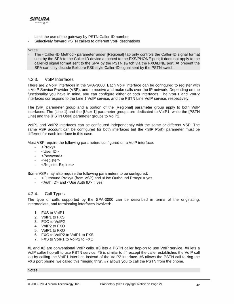
© 2003 - 2004 Sipura Technology, Inc Proprietary (See Copyright Notice on Page 2)
42
- Limit the use of the gateway by PSTN Caller-ID number - Selectively forward PSTN callers to different VoIP destinations Notes: - The <Caller-ID Method> parameter under [Regional] tab only controls the Caller-ID signal format
sent by the SPA to the Caller-ID device attached to the FXS/PHONE port; it does not apply to the caller-id signal format sent to the SPA by the PSTN switch via the FXO/LINE port. At present the SPA can only decode Bellcore FSK style Caller-ID signal sent by the PSTN switch.
4.2.3. VoIP Interfaces There are 2 VoIP interfaces in the SPA-3000. Each VoIP interface can be configured to register with a VoIP Service Provider (VSP), and to receive and make calls over the IP network. Depending on the functionality you have in mind, you can configure either or both interfaces. The VoIP1 and VoIP2 interfaces correspond to the Line 1 VoIP service, and the PSTN Line VoIP service, respectively. The [SIP] parameter group and a portion of the [Regional] parameter group apply to both VoIP interfaces. The [Line 1] and the [User 1] parameter groups are dedicated to VoIP1, while the [PSTN Line] and the [PSTN User] parameter groups to VoIP2. VoIP1 and VoIP2 interfaces can be configured independently with the same or different VSP. The same VSP account can be configured for both interfaces but the <SIP Port> parameter must be different for each interface in this case. Most VSP require the following parameters configured on a VoIP interface:
- <Proxy> - <User ID> - <Password> - <Register> - <Register Expires>
Some VSP may also require the following parameters to be configured:
- <Outbound Proxy> (from VSP) and <Use Outbound Proxy> = yes - <Auth ID> and <Use Auth ID> = yes
4.2.4. Call Types The type of calls supported by the SPA-3000 can be described in terms of the originating, intermediate, and terminating interfaces involved:
1. FXS to VoIP1 2. VoIP1 to FXS 3. FXO to VoIP2 4. VoIP2 to FXO 5. VoIP1 to FXO 6. FXO to VoIP2 to VoIP1 to FXS 7. FXS to VoIP1 to VoIP2 to FXO
#1 and #2 are conventional VoIP calls. #3 lets a PSTN caller hop-on to use VoIP service. #4 lets a VoIP caller hop-off to use PSTN service. #5 is similar to #4 except the caller establishes the VoIP call leg by calling the VoIP1 interface instead of the VoIP2 interface. #6 allows the PSTN call to ring the FXS port phone; we called this “ringing thru”. #7 allows you to call the PSTN from the phone. Notes:

© 2003 - 2004 Sipura Technology, Inc Proprietary (See Copyright Notice on Page 2)
43
- VoIP1-to-VoIP2 and VoIP2-to-VoIP1 are internal SIP calls. Signaling and media packets are sent to the loop back address 127.0.0.1. Hence call types #6 and #7 are possible even if the Ethernet port is not connected
The following sections describe each type of calls in more details.
4.2.5. Determining the Availability of the PSTN line SPA determines that the PSTN line is not available if the one of the following conditions is true: - PSTN line is not connected (loop current is 0 or Tip/Ring RMS voltage is below 1V) - PSTN line is being used by another extension. Tip/Ring RMS voltage lower than the threshold set
in <Line-In-Use Voltage> - PSTN line is ringing - PSTN line is being used by the SPA to serve another VoIP caller If the PSTN line is not available, the PSTN gateway function will be rejected; any VoIP caller requesting PSTN gateway functions will be turned down with a “Service Not Available” response. 4.3. Gateway Call Restriction by Dial Plan Gateway calls can be restricted on a per caller basis using dial plans. Up to 8 dial plans can be configured to restrict gateway calls in either direction. The corresponding SPA parameters are:
- [PSTN Line]<Dial Plan n>, n = 1 to 8 Notes:
- The dial plan length limit for <Dial Plan 1> through <Dial Plan 8> is 511 characters. This is less than that for the <Dial Plan> under [Line 1], which is 2047 characters.
- “gw0” – “gw4” syntaxes are not applicable to <Dial Plan 1> – <Dial Plan 8> (section 4.8) - While PSTN-To-VoIP calls must have dial plan (1 – 8) specified, the dial plan can be set to
“none” for VoIP-To-PSTN calls. If the dial plan is “none”, the SPA will take the FXO port off-hook and the VoIP caller will hear the PSTN dial tone directly from the PSTN switch immediately after successful authentication; the target number dialed by the VoIP caller will be directly interpreted by the PSTN company. On the other hand, if the dial plan is not “none”, the VoIP caller will hear the “Outside Dial Tone” generated by the SPA, where the caller will dial the target PSTN number. This number will be received and processed by the SPA with the chosen dial plan (the FXO port is still on-hook while the caller is entering the target number). If the target number is valid, the SPA then takes the FXO port off-hook and automatically dials the final target number (according to the chosen dial plan) out to the PSTN line. The characteristics of the Outside Dial Tone can be changed by modifying the <Outside Dial Tone> parameter (under [Regional] tab).
- You can “forward” all VoIP callers of the PSTN Line to a certain PSTN number (with or without authentication) by setting a hotline rule in the dial plan, such as (S0<:14089991234>) which sends all callers to 14089991234 automatically once the SPA auto-answers and authenticates the VoIP call. To make this works more transparently to the caller, you may disable authentication or add the caller to the access list.

© 2003 - 2004 Sipura Technology, Inc Proprietary (See Copyright Notice on Page 2)
44
4.4. Authentication Methods VoIP Callers can be authenticated by one of the following methods by setting the <VoIP Caller Auth Method> parameter:
1. No Authentication: All callers will be accepted for service. The dial plan to be used for all VoIP callers for this case is the one selected in <VoIP Caller Default DP>.
2. PIN: Caller is prompted to enter a VoIP PIN right after the call is answered (i.e., after the SPA replies with a 200 response). Up to 8 PIN’s, <VoIP Caller 1 PIN> to <VoIP Caller 8 PIN>, can be setup to access the PSTN gateway and each PIN can be assigned a different dial plan using the <VoIP Caller 1 DP> to <VoIP Caller 8 DP> parameters, respectively. The caller will hear a beep-beep-beep tone, known as the VoIP PIN Tone, as the prompt to enter the VoIP PIN. The tone will be played repeatedly until a PIN digit is received. After the first digit, the user by default will have 10s to enter each subsequent PIN digit. If no new PIN digit is entered for more than 10s, the SPA will terminate the call. This inter-PIN-digit timeout is set in the <VoIP PIN Digit Timeout> parameter. The PIN number entry must be ended by a pound (#) key. By default the caller will be given 3 chances to enter a valid PIN. If no valid PIN is received after 3 trials, the SPA will terminate the call. The number of VoIP PIN entry trials to allow can be changed by setting the <VoIP PIN Max Retry> parameter. If the last PIN entry is invalid, the VoIP PIN Tone will resume and the caller can re-enter the PIN again. The characteristics of the VoIP PIN Tone can be changed by setting <VoIP PIN Tone> ([Regional] tab). The VoIP PIN Tone should be set with a finite timeout (the default VoIP PIN tone has a timeout value of 10s). If no valid PIN is received after the maximum number of trials, the SPA will terminate the call.
3. HTTP Digest: SIP INVITE must contain a valid Authorization header that is computed based on an Auth ID and a password using MD5 digest algorithm. The Auth ID must be specified in the username parameter in the Authorization header. Up to 8 Auth ID/Passwords, <VoIP User 1 Auth ID>/<VoIP User 1 Password> to <VoIP User 8 Auth ID>/<VoIP User 8 Password>, can be setup to access the PSTN gateway. Each Auth ID/Password can be assigned a different dial plan using the <VoIP User 1 DP> to <VoIP User 8 DP> parameters, respectively. If the inbound INVITE to the PSTN Line does not have an Authorization header or the credentials it contains are invalid, the SPA will reply with a 401 response. If the username parameter in the Authorization header does not match any of the <VoIP User n Auth ID>, n = 1 to 8, the SPA will reply with a 403 response. If the INVITE request a target PSTN number (as in one-stage dialing) that is not allowed by the corresponding dial plan for that caller, the SPA will also reply with a 403 response.
VoIP callers can also be gated by a list of Caller-ID patterns before authentication rules are applied. These patterns are specified in <VoIP Caller ID Pattern> which is a comma separate list of Caller-ID patterns. The VoIP Caller-ID is extracted from the inbound INVITE request FROM header User-ID field. If the FROM header has “Anonymous” (case-insensitive) in the display-name field, however, the SPA treats the VoIP Caller-ID as “Anonymous”. Each Caller-ID pattern is a case insensitive alpha-numeric string with special wildcard characters ‘?’ and ‘*’ , which stands for “any single digit” and “0 or more of any digits” respectively. For example: 1408*,15101234567,18??*,anonymous,jsmith. It is recommended not to insert white spaces before and after the comma, although they are allowed. If <VoIP Caller ID Pattern> is blank, all VoIP callers will be processed by the SPA for authentication and subsequent gateway services upon successful authentication. If <VoIP Caller ID Pattern> is not blank, then the VoIP Caller ID must match one of the given patterns or else will be rejected by the SPA with a 403 response without further processing. In addition, a VoIP Caller can be automatically accepted for PSTN gateway access without going through the authentication process if the source IP address of the inbound INVITE request matches one of the pattern specified in the <VoIP Access List>. This is a comma separated list of IP address patterns, also with special wildcard characters ‘?’ and ‘*’. For example:192.168.2.*,66.12?.12?.4. If the list is not blank and the source IP address of the inbound INVITE matches any of the patterns in the list, the VoIP caller will be granted access to the PSTN gateway as if the Authentication Method is

© 2003 - 2004 Sipura Technology, Inc Proprietary (See Copyright Notice on Page 2)
45
set to “none” (and so the <VoIP Caller Default DP> applies and 1-stage dialing is possible in this case). Notes: - One-stage dialing is possible only if <VoIP Caller Auth Method> is “none” or “HTTP Digest”.
Unless the caller number is in the <VoIP Access List >, the “PIN” method requires 2-stage dialing: Caller will need to dial the target PSTN number after entering a valid PIN. One-stage dialing can be globally disabled by setting <One Stage Dialing> to “no”, for which case all VoIP callers (including Line 1) will be required to dial the PSTN target number upon successful authentication.
- If the VoIP Caller is calling from Line 1 of the same unit. Authentication is skipped regardless the setting of <VoIP Caller Auth Method>. The dial plan to use in this case in <Line 1 VoIP Caller DP> for normal operation, or <Line 1 Fallback DP> for Line-1-Fallback-To-PSTN operation (when network link is down or Line 1 registration fails).
PSTN Callers can be authenticated by one of the following methods by setting the <PSTN Caller Auth Method> parameter:
1. No Authentication: All Callers will be accepted for service. In this case the dial plan to be used for all PSTN callers is taken from <PSTN Caller Default DP>.
2. PIN: Caller is prompted to enter a PSTN PIN right after the call is auto-answered by the SPA (by taking the FXO port off-hook). Up to 8 PIN’s, <PSTN Caller 1 PIN> to <PSTN Caller 8 PIN>, can be setup to access the VoIP gateway and each PIN can be assigned a different dial plan using the <PSTN Caller 1 DP> to <PSTN Caller 8 DP> parameters, respectively. The caller will hear a beep-beep-beep tone, known as the PSTN PIN Tone, as the prompt to enter the PSTN PIN. The tone will be played repeatedly until a PIN digit is received. After the first digit, the user by default will have 10s to enter each subsequent PIN digit. If no new PIN digit is entered for more than 10s, the SPA will play the Reorder Tone and then terminate the call by taking the FXO port on-hook. This inter-PIN-digit timeout is set in the <PSTN PIN Digit Timeout> parameter. The PIN number entry must be ended by a pound (#) key. By default the caller will be given 3 chances to enter a valid PIN. If no valid PIN is received after 3 trials, the SPA will terminate the call. The number of PSTN PIN entry trials to allow can be changed by setting the <PSTN PIN Max Retry> parameter. If the last PIN entry is invalid, the PSTN PIN Tone will resume and the caller can re-enter the PIN again. The characteristics of the PSTN PIN Tone can be changed by modifying <PSTN PIN Tone> ([Regional] tab). The PSTN PIN Tone should be set with a finite timeout (the default PSTN PIN tone has a timeout value of 10s). If no valid PIN is received after the maximum number of trials, the SPA will play reorder tone and then terminate the call.
PSTN callers can also be gated by a list of Caller-ID patterns before authentication rules are applied. These patterns are specified in <PSTN Caller ID Pattern>, a comma separate list of Caller-ID patterns. The PSTN Caller-ID is decoded from the signal delivered by the PSTN switch. It is highly recommended that the PSTN line connected to the SPA comes with the caller-id delivery service. If Caller-ID signal is not present or the Caller-ID number is blocked, the SPA treats the PSTN Caller-ID as “Anonymous”. Each Caller-ID number is a case-insensitive alphanumeric string with special wildcard characters ‘?’ and ‘*’ , which stands for “any single digit” and “0 or more of any digits” respectively. For example: 1408*,15101234567,18??*,anonymous. It is recommended not to insert white spaces before and after the comma, although they are allowed. If <PSTN Caller ID Pattern> is blank, all PSTN callers will be processed by the SPA for authentication and subsequent gateway services upon successful authentication. If <PSTN Caller ID Pattern> is not blank, then the PSTN Caller ID must match one of the given patterns or else the SPA will not answer the call.
In addition, a PSTN caller can be automatically accepted for VoIP gateway access without going through the authentication process if the Caller-ID number matches one of the patterns specified in the <PSTN Access List>. This is a comma separated list of Caller-ID patterns, also with special

© 2003 - 2004 Sipura Technology, Inc Proprietary (See Copyright Notice on Page 2)
46
wildcard characters ‘?’ and ‘*’ (same syntax as <PSTN Caller ID Pattern>). If the list is not blank and the Caller-ID number matches any of the patterns in the list, that PSTN caller will be granted access to the VoIP gateway as if the Authentication Method is set to “none” (and so the <PSTN Caller Default DP> applies in this case).
Notes: - Only 2-stage dialing is possible with PSTN-To-VoIP gateway calls The configuration parameters mentioned in this section are:
- [PSTN Line]<One Stage Dialing> - [PSTN Line]<VoIP Auth Method> - [PSTN Line]<VoIP Caller ID Pattern> - [PSTN Line]<VoIP Access List> - [PSTN Line]<VoIP PIN Max Retry> - [PSTN Line]<VoIP PIN Digit Timeout> - [Regional]<VoIP PIN Tone> - [PSTN Line]<VoIP Caller Default DP> - [PSTN Line]<VoIP Caller n PIN>, n = 1 to 8 - [PSTN Line]<VoIP Caller n DP>, n = 1 to 8 - [PSTN Line]<VoIP User n Auth ID>, n = 1 to 8 - [PSTN Line]<VoIP User n Password>, n = 1 to 8 - [PSTN Line]<VoIP User n DP>, n = 1 to 8 - [PSTN Line]<Line 1 VoIP Caller DP> - [PSTN Line]<Line 1 Fallback DP> - [PSTN Line]<PSTN Auth Method> - [PSTN Line]<PSTN Caller ID Pattern> - [PSTN Line]<PSTN Access List> - [PSTN Line]<PSTN PIN Max Retry> - [PSTN Line]<PSTN PIN Digit Timeout> - [Regional]<PSTN PIN Tone> - [PSTN Line]<PSTN Caller Default DP> - [PSTN Line]<PSTN Caller n DP>, n = 1 to 8 4.5. VoIP-To-PSTN Calls (Call Type #4) In order to obtain PSTN services via VoIP, the VoIP caller must establish connection with the SPA-3000 by way of a standard SIP INVITE request addressed to the SIP account configured under the [PSTN Line] tab. The PSTN gateway can be configured to support 1-stage and 2-stage dialing as described below. This is call type #4 and the voice path for this type of calls is (5) (6) (7)
4.5.1. One-Stage Dialing One-stage dialing is possible if <One Stage Dialing> is “yes”, <VoIP Authentication Method> is “none” or “HTTP Digest” or if the source IP of the inbound INVITE matches one of the patterns specified in <VoIP Access List>. To perform one-stage dialing, the Request-URI of the INVITE to the PSTN Line should have the form dialed-number@SPA-Address, where dialed-number is the target PSTN number as “dialed” by the VoIP caller, and SPA-Address is a valid address of the SPA, such as 10.0.0.100:5061.
If the PSTN line is currently not available, the SPA replies to the INVITE with a 503 response. Otherwise, it compares the dialed-number with the <User ID> configured for the PSTN Line. If the

© 2003 - 2004 Sipura Technology, Inc Proprietary (See Copyright Notice on Page 2)
47
dialed-number is not specified or is the same as <User ID>, the SPA interprets this as a request for 2-stage dialing (see next section). Otherwise, the SPA processes the dialed-number by a corresponding dial plan. If the dial plan processing fails, the SPA replies with a 403 response. Otherwise, it replies with a 200 response and at the same time takes the FXO port off hook and dials the final number returned from the dial plan to the PSTN switch.
4.5.2. Two-Stage Dialing In 2-stage dialing, the VoIP caller will need to dial the target PSTN number upon successful authentication. If the dial plan configured for this VoIP caller is “none”, SPA will take the FXO port off-hook but will not dial any digits automatically after accepting the caller for gateway service. Hence the caller will hear the dial tone directly provided by the PSTN switch, which will interpret the target number dialed by the VoIP caller. If the dial plan is not “none”, the SPA will play the Outside Dial Tone to direct the VoIP caller to dial the PSTN number; the FXO port will stay on-hook while the SPA collects a complete PSTN target number from the caller according to the selected dial plan. If the dialed number is valid, the SPA takes the FXO port off-hook and dials the final target number returned from the dial plan to the PSTN switch accordingly. If the dialed number is invalid, the SPA terminates the call immediately. To invoke 2-stage dialing, the VoIP caller can form a SIP INVITE request to send the PSTN Line without a user-id field in the Request-URI or with a user-id that matches exactly the <User ID> of the PSTN Line. Other user-id in the Request-URI will be treated as a request for 1-stage dialing (Section 4.5.1) if 1-stage dialing is enabled, or dropped by the SPA (as if no user-id is given) if 1-stage dialing is disabled. The VoIP PIN digits and target number digits must be sent to the SPA out-of-band using the RFC2833 protocol (a.k.a. AVT Tone). The SPA does not accept any DTMF digits sent to it in-band over VoIP. Notes: - VoIP-To-PSTN Gateway function can be globally disabled by setting <VoIP-To-PSTN Gateway
Enable> to “no”; SPA will reply with a 503 response to inbound INVITE sent to the PSTN Line - If the PSTN line is not connected, or is in use by another extension or another VoIP caller, the
SPA will reply with a 503 response to inbound INVITE sent to the PSTN Line - The <User ID> of the PSTN Line can be blank. In that case Registration should be disabled for
the PSTN Line - When the SPA decides to accept an incoming INVITE, it immediately sends a 180 response to
the VoIP caller, and eventually a 200 response to “answer” the call. You can set the desired delay before the SPA sends out the 200 response after the 180 response in the <VoIP Answer Delay> parameter. This delay can be 0.
- You can insert a small amount of delay before the SPA starts auto-dialing the final target number to the PSTN line after the SPA takes the FXO port off-hook. This delay is specified in the <PSTN Dialing Delay> parameter. This delay is used to make sure the PSTN switch is ready to receive DTMF before the SPA starts dialing.
Below is the pseudo code for accepting a VoIP caller for PSTN gateway service. If (VoIP Caller-ID Pattern Blank or VoIP Caller-ID Matches a VoIP Caller-ID Pattern) { If (VoIP Caller in VoIP Access-List or Authentication Disabled) { Reply 200 Start PSTN Gateway Service } Else {

© 2003 - 2004 Sipura Technology, Inc Proprietary (See Copyright Notice on Page 2)
48
If (Authentication Method is HTTP) { If (Authorization Invalid) { Reply 401 } Else { If (Target Number Valid) { Reply 200 Start PSTN Gateway Service } Else { Reply 403 } } } Else { Reply 200 Get VoIP PIN from Caller If (Valid PIN) { Start PSTN Gateway Service } Else { Send BYE } } } } Else { Reply 403 } The configuration parameters mentioned in this section are: - [PSTN Line]<One Stage Dialing> - [PSTN Line]<VoIP Caller Auth Method> - [PSTN Line]<VoIP Access List> - [PSTN Line]<VoIP Caller ID Pattern> - [PSTN Line]<VoIP Caller n PIN>, n = 1 to 8 - [PSTN Line]<VoIP User n Auth ID>, n = 1 to 8 - [PSTN Line]<VoIP User n Password>, n = 1 to 8 - [PSTN Line]<VoIP Caller n DP>, n = 1 to 8 - [PSTN Line]<VoIP User n DP>, n = 1 to 8 - [PSTN Line]<User ID> - [PSTN Line]<VoIP-To-PSTN Gateway Enable> - [PSTN Line]<VoIP Answer Delay> - [PSTN Line]<PSTN Dialing Delay> 4.6. PSTN-To-VoIP Calls (Call Type #3) This is call type #3 with the voice path (7) (6) (5). PSTN-To-VoIP Calls can be made with 2-stage dialing only. The only authentication method available is the PIN method. The SPA auto-answers (i.e., takes the FXO port off-hook) after the PSTN line rings for a certain number of seconds. This auto-answer delay is configured in the <PSTN Answer Delay> parameter, and should be set to a larger enough value to allow enough time for the SPA to decode the Caller-ID signal sent by the
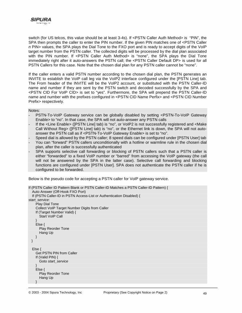
© 2003 - 2004 Sipura Technology, Inc Proprietary (See Copyright Notice on Page 2)
49
switch (for US telcos, this value should be at least 3-4s). If <PSTN Caller Auth Method> is “PIN”, the SPA then prompts the caller to enter the PIN number. If the given PIN matches one of <PSTN Caller n PIN> values, the SPA plays the Dial Tone to the FXO port and is ready to accept digits of the VoIP target number from the PSTN caller. The collected digits will be processed by the dial plan associated with the PIN number. If <PSTN Caller Auth Method> is “none”, the SPA plays the Dial Tone immediately right after it auto-answers the PSTN call; the <PSTN Caller Default DP> is used for all PSTN Callers for this case. Note that the chosen dial plan for any PSTN caller cannot be “none”. If the caller enters a valid PSTN number according to the chosen dial plan, the PSTN generates an INVITE to establish the VoIP call leg via the VoIP2 interface configured under the [PSTN Line] tab. The From header of the INVITE will be the VoIP2 account, or substituted with the PSTN Caller-ID name and number if they are sent by the PSTN switch and decoded successfully by the SPA and <PSTN CID For VoIP CID> is set to “yes”. Furthermore, the SPA will prepend the PSTN Caller-ID name and number with the prefixes configured in <PSTN CID Name Perfix> and <PSTN CID Number Prefix> respectively. Notes: - PSTN-To-VoIP Gateway service can be globally disabled by setting <PSTN-To-VoIP Gateway
Enable> to “no”. In that case, the SPA will not auto-answer any PSTN calls - If the <Line Enable> ([PSTN Line] tab) is “no”, or VoIP2 is not successfully registered and <Make
Call Without Reg> ([PSTN Line] tab) is “no”, or the Ethernet link is down, the SPA will not auto-answer the PSTN call as if <PSTN-To-VoIP Gateway Enable> is set to “no”.
- Speed dial is allowed by the PSTN caller; 8 speed dials can be configured under [PSTN User] tab - You can “forward” PSTN callers unconditionally with a hotline or warmline rule in the chosen dial
plan, after the caller is successfully authenticated - SPA supports selective call forwarding or blocking of PSTN callers such that a PSTN caller is
either “forwarded” to a fixed VoIP number or “barred” from accessing the VoIP gateway (the call will not be answered by the SPA in the latter case). Selective call forwarding and blocking functions are configured under [PSTN User]. SPA does not authenticate the PSTN caller if he is configured to be forwarded.
Below is the pseudo code for accepting a PSTN caller for VoIP gateway service. If (PSTN Caller ID Pattern Blank or PSTN Caller-ID Matches a PSTN Caller-ID Pattern) { Auto Answer (Off-Hook FXO Port) If (PSTN Caller-ID in PSTN Access-List or Authentication Disabled) { start_service: Play Dial Tone Collect VoIP Target Number Digits from Caller If (Target Number Valid) { Start VoIP Call } Else { Play Reorder Tone Hang Up } } Else { Get PSTN PIN from Caller If (Valid PIN) { Goto start_service } Else { Play Reorder Tone Hang Up }

© 2003 - 2004 Sipura Technology, Inc Proprietary (See Copyright Notice on Page 2)
50
} } The configuration parameters mentioned in this section are:
- [PSTN Line]<PSTN-To-VoIP Gateway Enable> - [PSTN Line]<Line Enable> - [PSTN Line]<Make Call Without Reg> - [PSTN Line]<PSTN Caller ID Pattern> - [PSTN Line]<PSTN Access List> - [PSTN Line]<PSTN Answer Delay> - [PSTN Line]<PSTN CID For VoIP CID> - [PSTN Line]<PSTN CID Number Prefix> - [PSTN Line]<PSTN CID Name Prefix> - [PSTN Line]<PSTN Caller Auth Method> - [PSTN Line]<PSTN Caller n PIN>, n = 1 to 8 - [PSTN User] <Speed Dial n>, n = 2 to 9 - [PSTN User]<Cfwd Seln Caller>, n = 1 to 8 - [PSTN User]<Cfwd Seln Dest>, n = 1 to 8 4.7. Terminating Gateway Calls A gateway call has two call legs: the PSTN call leg and the VoIP call leg. A gateway call is terminated when either call leg is ended. It is very important that the SPA takes the FXO port on-hook when the call terminates or else the PSTN line cannot be used again. The SPA detects that the PSTN call leg is ended when one of the following conditions occur during a call:
1. The PSTN line tip-to-ring voltage drops to a very low value (< 1V) for a finite duration of time. This can happen if the PSTN line is disconnected from the FXO port, or when the PSTN switch sends a CPC signal to indicate that the call has been disconnected. The duration of this very low voltage must last for at least the length as specified in <Min CPC Duration>. The detection of CPC signal can be turned off by setting <Detect CPC> to “no”.
2. A polarity reversal is detected at the FXO port. The polarity reversal must last for at least 100ms or it will be ignored by the SPA. The detection of polarity reversal signal can be turned off by setting <Detect Polarity Reversal> to “no”
3. Disconnect Tone detected on the FXO port. The characteristics of the Disconnect Tone can be changed by modifying the <Disconnect Tone> parameter. The detection of Disconnect Tone can be turned off by setting <Detect Disconnect Tone> to “no”
4. When there is no voice activity detected from the PSTN line for a continuous period of time. The condition must last in continuation for at least the length of time specified in the <PSTN Long Silence Duration> parameter. The sensitivity of the detection can be adjusted by setting <PSTN Silence Threshold>; the higher the threshold, the easier the SPA will detect voice activity. The detection of this condition can be turned off by setting <Detect PSTN Long Silence> to “no”.
The SPA determines that the VoIP connection is ended (or broken) if: 1. SPA receives a SIP BYE request from the VoIP peer 2. No RTP packets received from the VoIP Peer for a continuous period of time larger than <VoIP
Long Silence Duration> seconds. The detection of this condition can be turned off by setting <Detect VoIP Long Silence> to “no”
3. VoIP peer fails to respond to a periodic dialog refresh request from the SPA. The interval between periodic refresh messages is set in the <VoIP DLG Refresh Intvl>. The refresh message
© 2003 - 2004 Sipura Technology, Inc Proprietary (See Copyright Notice on Page 2)
51
is a SIP Re-INVITE request which the VoIP peer must reply with a 200 class response. The sending of dialog refresh messages can be disabled by setting <VoIP DLG Refresh Intvl> to 0.
When any of the above occurs, the SPA takes the FXO port on hook and sends the proper SIP signaling messages to end the VoIP call leg. In addition, you can limit the total duration of a VoIP gateway call and of a PSTN gateway call by setting the <PSTN-To-VoIP Call Max Dur> and <VoIP-To-PSTN Call Max Dur> parameters, respectively (setting either of these parameters to 0 imply the total duration of the gateway call is unlimited).
Finally, the VoIP or PSTN caller can enter * * # before hanging up to force the SPA to hang up the FXO port and tear down the VoIP call leg. This command can only be sent by the calling party; the SPA will not act on the command if sent by the called party. This command is especially useful if none of the PSTN disconnect signals can be detected reliably by the SPA.
The configuration parameters mentioned in this section are:
- [PSTN Line]<Detect CPC> - [PSTN Line]<Min CPC Duration> - [PSTN Line]<Detect PSTN Long Silence> - [PSTN Line]<PSTN Long Silence Duration> - [PSTN Line]<Detect VoIP Long Silence> - [PSTN Line]<VoIP Long Silence Duration> - [PSTN Line]<Disconnect Tone> - [PSTN Line]<Detect Polarity Reversal> - [PSTN Line]<Detect Disconnect Tone> - [PSTN Line]<PSTN Silence Threshold> - [PSTN Line]<VoIP DLG Refresh Intvl> - [PSTN Line]<PSTN-To-VoIP Call Max Dur> - [PSTN Line]<VoIP-To-PSTN Call Max Dur> 4.8. Line 1 VoIP Outbound Call Routing (Call Type #7) The voice path for this call type is (1) (2) (4) (6) (7). Calls made from Line 1 are routed through the configured Line 1 service provider by default. This behavior can be overridden by IP dialing where the calls can be routed to any IP address entered by the user. SPA-3000 allows more flexible call routing with the addition of 4 sets of gateway parameters and new dial plan parameters:
- [Line 1]<Gateway n>, n = 1 to 4 - [Line 1]<GWn NAT Mapping Enable>, n = 1 to 4 - [Line 1]<GWn Auth ID>, n = 1 to 4 - [Line 1]<GWn Password>, n = 1 to 4
Gateways 1 to 4 are specified in a dial plan with the special identifiers “gw1”, … “gw4”. In addition, the identifier “gw0” represents the internal PSTN gateway via the FXO port. One can specify in the dial plan to use gwn (n = 0,1,2,3,4) when making certain calls. If more gateways are needed, one can specify any gateway address in the dial plan. There are 3 dial plan parameters that can be used with call routing: “usr”, “pwd”, and “nat” which are, respectively, the user-id (or authentication-id) and password to be used for authentication with the given gateway, and whether to enable NAT mapping when routing calls through that gateway. Below are some examples
Examples Description <9,:>xx.<:@gw1> User dials 9 to start Outside Dial Tone, followed by 1 or
more digits, and the SPA routes the call to Gateway 1. [93]11<:@gw0> Route 911 and 311 calls to the local PSTN gateway

© 2003 - 2004 Sipura Technology, Inc Proprietary (See Copyright Notice on Page 2)
52
<8,:1408>xxxxxxx<:@pstn.sipura.com:5061;usr=joe;pwd=joe_pwd;nat>
User dials 8 to start Outside Dial Tone. When user dials a 7-digit number, SPA prepends it with 1408 and routes the call to pstn.sipura.com:5061, with user-id = joe, and pwd = bell_pwd, and NAT mapping enabled
<8,:1408>xxxxxxx<:@gw2:5061;usr=”Alex Bell”;pwd=”anything”;nat=no>
User dials 8 to start Outside Dial Tone. When user dials a 7-digit number, SPA prepends it with 1408 and routes the call to Gateway 2, but to port 5061 with user-id = “Alex Bell”, pwd = bell_pwd, and NAT mapping disabled
With the call-routing capability, one can use the same phone to make outbound calls to Line 1 VoIP or the PSTN line attached to the FXO port. In fact, the SPA can bridge a 3-way conference with one VoIP leg and one PSTN call leg. One can also setup multiple PSTN gateways at different locations and configured Line 1 to use different gateway when dialing certain numbers.
Notes: - gw0 – gw4 identifiers can only be used in [Line 1]<Dial Plan>. They are not allowed in [PSTN
Line]<Dial Plan n>, n = 1 to 8 - The “usr”, “pwd”, and “nat” parameters, on the other hand, are allowed in all dial plans - The PSTN gateway will apply the <Line 1 VoIP Caller DP> to further limit the calls that can be
made by the Line 1 caller to the PSTN; this dial plan may be set to “none”. In general calls routed from Line 1 to the PSTN are processed by 2 dial plans.
- The SPA does not support call transferring the VoIP peer to the PSTN peer, or vice versa, in a 3-way call or 3-way conference that involves one VoIP call leg and one PSTN call leg.
4.9. Line 1 VoIP Fallback to PSTN When power is removed from the SPA-3000, the FXS port will be connected to the FXO port. In this case, the telephone attached to the FXS port is electrically connected to the PSTN service via the FXO port. When power is applied to the SPA, the FXS port will be disconnected from the FXO port. However, if the PSTN line is in use when the power is applied to the SPA, the relay will not be flipped until the PSTN line is released. This is done so that the SPA will not interrupt any call in progress on the PSTN line.
When Line 1 VoIP service is down (due to registration failure or loss of Ethernet link), SPA can be configured to automatically route all outbound calls to the internal gateway if <Auto PSTN Fallback> ([Line 1] tab) is set to “yes”. The PSTN gateway applies the <Line 1 Fallback DP> to further limit the calls that can be made by the Line 1 caller during the fallback operation; this dial plan may be set to “none”. This case also belongs to call type #7 and the voice path is (1) (2) (4) (6) (7).
4.10. VoIP-To-PSTN Calls Via VoIP1 Interface (Call Type #5) All PSTN gateway calls can be routed from the VoIP2 interface if the user can dedicated one VoIP account for the PSTN Line. Line 1 and the PSTN Line can also be configured with the same VoIP account if they use different <SIP Port>. If the service provider allows multiple REGISTER contacts and simultaneous ringing, both VoIP interfaces can register periodically with the service provider. In this case, both VoIP interfaces will receive inbound calls to this shared account. The PSTN Line should be configured with a sufficiently long <VoIP Answer Delay> before the call is automatically answered to provide PSTN gateway function.
If the service provider does not allow more than one REGISTER contacts, then the PSTN Line should not register. In this case, only Line 1 will ring on the inbound call to this VoIP account (since it is the only line registered with the service provider). Line 1 can have the call “forwarded” to the PSTN line after a configurable delay using the Call-Forward-On-No-Answer feature with “gw0” as the forward

© 2003 - 2004 Sipura Technology, Inc Proprietary (See Copyright Notice on Page 2)
53
destination. This is Call Type #5 and the voice path is (3) (8) (7). Similarly, Line 1 can apply Call-Forward-All, Call-Forward-On-Busy, and Call-Forward-Selective features and send the caller to use the PSTN gateway.
Only the PIN Authentication method is allowed when a VoIP caller is forwarded to access the PSTN gateway from Line 1. If <VoIP Caller Auth Method> is “HTTP Digest”, the SPA treats it as if VoIP caller authentication is disabled. Line 1 call forward destinations are configured under the [User 1] tab.
An extension to the Forward-To-GW0 feature is to forward the caller to a specific PSTN number, using the syntax PSTN-number@gw0 in the call forward destination in [User 1]. When using this with Call-Forward-Selective for instance, one can come up with some very interesting applications. For example, you can forward all callers with 408 area code to 14081234567, or all callers with 800 area code to 18005558355. When this syntax is used, authentication is not skipped regardless the settings of <VoIP Caller Auth Method> and the target PSTN number will be automatically dialed by the SPA once the caller is forwarded to the gw0.
4.11. PSTN Call Ring Thru Line 1 (Call Type #6) The voice path is (7) (6) (4) (2) (1). This feature is enabled by setting <PSTN Ring Thru Line 1> to “yes”. If enabled, all incoming PSTN calls will ring the Line 1 phone regardless the VoIP gateway function is enabled on the SPA or not. Hence the same phone can be used to receive calls from Line 1 VoIP and from the PSTN. If Line 1 is already engaged in another VoIP call at the moment the PSTN line rings, the SPA presents the PSTN call alert signal to the user by playing a call-waiting tone, and the user can then switch between the PSTN call and the VoIP call by hook-flashing (as she normally would with 2 VoIP calls).
SPA implements the ring-thru feature by making an internal VoIP call from the VoIP2 interface to the VoIP1 interface. A by-product of this approach is that the call forwarding and distinctive ringing settings on Line 1 also apply to the PSTN call ringing thru Line 1. Ring thru stops as soon as the VoIP gateway auto-answers the PSTN call, or the VoIP1 interface returns a busy signal to VoIP2.
If Caller-ID is available with the PSTN call, SPA will present it in the FROM header of the internal SIP INVITE message sent from the VoIP2 to the VoIP1 interface, which then passes it on to the phone attached to the FXS port as Type I or Type II Caller-ID. For this to happen, the SPA must be allowed sufficient time to completely decode the PSTN Caller-ID signal before it can relay the decoded caller-id information to the phone. For US Type I Caller-ID, the CID signal starts shortly after the first ring and ends before the second ring. The first ring usually lasts for about 2s, the interval between the first and second ring is about 4s, and a typical Caller-ID signal lasts for about 1s. If the first ring that SPA sends to the phone is of the same length as the first ring sent by the PSTN switch to the SPA, the SPA should be configured to ring thru Line 1 at least 1s after it detects that the PSTN line is ringing, such that by the time the SPA sends the Type I Caller-ID signal to the phone, it would have completely decoded the PSTN Caller-ID signal. This ring thru delay is configured in <PSTN Ring Thru Delay>. In a call-waiting scenario, the SPA needs to send Type II Caller-ID to the phone. In that case the delay should include the length of the PSTN first ring, which is usually much longer than the length of the first burst of call-waiting tone generated by the SPA. In this example, the delay should be about 3s and it can be configured in <PSTN Ring Thru CWT Delay>. In both cases, the <PSTN Answer Delay> should be set large enough for the complete Caller-ID signal to be sent to the phone before the SPA auto-answers the call. If PSTN Caller-ID is not available or the SPA has not completely decoded the PSTN Caller-ID signal by the time it sends Caller-ID signal to the phone, the signal it sends will be encoded with the VoIP account information configured for the [PSTN Line] instead of the PSTN Caller-ID name and number. Note that <PSTN CID For VoIP CID> does not apply when ringing thru Line 1.
When the PSTN call rings thru Line 1, you can assign a different <Default Ring> under the <PSTN User] tab so that it will sound differently from normal VoIP calls to Line 1. The <Default Ring> value
© 2003 - 2004 Sipura Technology, Inc Proprietary (See Copyright Notice on Page 2)
54
affects both ringing signal and call-waiting tone. Unlike the <Default Ring> setting under the [User 1] tab, the <Default Ring> parameter under the [PSTN User] tab has the extra choice of “Follow Line 1”, which means to follow the Line 1 ringer settings (including distinctive ringing rules) instead of forcing it to use a particular ring cadence.
When the SPA inserts the decoded PSTN caller-id name and number into the SIP INVITE message sent to the VoIP1 interface, it also prepends the name and number by the prefixes configured in <PSTN CID Number Perfix> and <PSTN CID Name Prefix> respectively.
If the PSTN caller hangs up before Line 1 or the VoIP gateway answers the call, the Line 1 phone may continue to ring a little longer since it takes a few seconds for the SPA to realize that the PSTN line has indeed stopped ringing. This delay can be modified by setting the <PSTN Ring Timeout> value (default is 5s).
The configuration parameters mentioned in this section are:
- [PSTN Line]<PSTN Ring Thru Line 1> - [PSTN Line]<PSTN Ring Thru Delay> - [PSTN Line]<PSTN Ring Thru CWT Delay> - [PSTN Line]<PSTN Ring Timeout> - [PSTN Line]<PSTN Answer Delay> - [PSTN Line]<PSTN CID For VoIP CID> - [PSTN Line]<PSTN CID Name Prefix> - [PSTN Line]<PSTN CID Number Prefix> - [PSTN Line]<PSTN Ring Timeout> - [PSTN User]<Default Ring>
4.12. Symmetric RTP In a normal VoIP connection, the SPA sends RTP packets to the destination as specified in the SDP sent by the VoIP peer. When <Symmetric RTP> is set to “yes”, however, SPA will change the destination to send RTP packets to the source IP address and port of the inbound RTP packet last received by the SPA. This setup can facilitate symmetric NAT traversal at the remote end. The parameter is available under both [Line 1] and [PSTN Line] tabs. - [Line 1] <Symmetric RTP> - [PSTN Line] <Symmetric RTP> 4.13. Configuration Examples and Call Scenarios In this section we walk through some typical scenarios where the SPA-3000 can be applied.
4.13.1. Setup VoIP1 and VoIP2 With Separate VoIP Accounts You have 2 FWD (Free World Dialup) accounts A and B, where A is for regular VoIP service and B dedicated for gateway functions. a) Without Using STUN or NAT Mapping
[SIP]<STUN Enable> = no [SIP]<Substitute VIA Addr> = no [Line 1]<Line Enable> = yes [Line 1]<SIP Port> = 5060 [Line 1]<NAT Mapping Enable] = no [Line 1]<NAT Keep Alive Enable] = no

© 2003 - 2004 Sipura Technology, Inc Proprietary (See Copyright Notice on Page 2)
55
[Line 1]<Proxy> = fwd.pulver.com [Line 1]<Outbound Proxy> = fwdnat.pulver.com:5082 [Line 1]<Use Outbound Proxy> = yes [Line 1]<Use OB Proxy in Dlg> = yes [Line 1]<User ID> = userid_A [Line 1]<Password> = password_A [Line 1]<Register> = yes [Line 1]<Register Expires> = 3600 [PSTN Line]<Line Enable> = yes [PSTN Line]<SIP Port> = 5061 [PSTN Line]<NAT Mapping Enable] = no [PSTN Line]<NAT Keep Alive Enable] = no [PSTN Line]<Proxy> = fwd.pulver.com [PSTN Line]<Outbound Proxy> = fwdnat.pulver.com:5082 [PSTN Line]<Use Outbound Proxy> = yes [PSTN Line]<Use OB Proxy in Dlg> = yes [PSTN Line]<User ID> = userid_B [PSTN Line]<Password> = password_B [PSTN Line]<Register> = yes [PSTN Line]<Register Expires> = 3600 b) With STUN and NAT Mapping
Similar to (a) with the following changes: [SIP]<STUN Enable> = yes [SIP]<NAT Keep Alive Intvl] = 15 [SIP]<Substitute VIA Addr> = yes [SIP]<STUN Server> = stun.fwdnet.net [Line 1]<NAT Mapping Enable] = yes [Line 1]<NAT Keep Alive Enable] = yes [Line 1]<NAT Keep Alive Msg] = (blank) [Line 1]<NAT Keep Alive Dest> = $PROXY [Line 1]<Use Outbound Proxy> = no [PSTN Line]<NAT Mapping Enable> = yes [PSTN Line]<NAT Keep Alive Enable] = yes [PSTN Line]<NAT Keep Alive Msg] = (blank) [PSTN Line]<NAT Keep Alive Dest> = $PROXY [PSTN Line]<Use Outbound Proxy> = no
4.13.2. Setup VoIP1 and VoIP2 with Same VoIP Account You have only one VoIP account and your service provider does not allow multiple registration. Setup the subscriber and proxy information as in the last section (with A = B) and make the following changes: [PSTN Line]<Register> = no [PSTN Line]<Make Call Without Reg> = yes [PSTN Line]<Ans Call Without Reg> = yes
4.13.3. PSTN-To-VoIP Call Without Ringing Thru Line 1 Assume the VoIP2 interface is properly configured and successfully registered, and

© 2003 - 2004 Sipura Technology, Inc Proprietary (See Copyright Notice on Page 2)
56
[PSTN Line]<PSTN Ring Thru Line> = no [PSTN Line]<PSTN Answer Delay> = 14 [PSTN Line]<PSTN Caller 1 PIN> = 1234 [PSTN Line]<PSTN Caller n PIN> = (blank), n = 2 to 8 [PSTN Line]<PSTN Caller 1 DP> = 1 [PSTN Line]<Dial Plan 1> = (1408xxxxxxx|408xxxxxxx|xxxxxxx|1800xxxxxxx|800xxxxxxx) [PSTN Line]<PSTN Caller Auth Method> = PIN [PSTN Line]<PSTN PIN Max Retry> = 2 [PSTN Line]<PSTN CID For VoIP CID> = no [Regional]<PSTN PIN Tone> = (default) [Regional]<Dial Tone> = (default) [Regional]<Reorder Tone> = (default)
When a user calls the PSTN line connected to the FXO port, the SPA VoIP gateway answers the call after 3 rings (about 14s). The SPA then prompts the caller to enter a PIN number by playing a beep-beep-beep tone. The user enters 1 and the tone goes again. The user continues to enter 234#. The SPA then plays a regular dial tone to prompt the user to enter a VoIP target number. The caller in this case is limited by the chosen dial plan to call 7-digit numbers, and 408 and 800 numbers with 10 or 11 digit dialing. The VoIP target will see the Caller-ID of the VoIP2 interface instead of the name and number of the PSTN caller.
When the call is done, either side can hang up. Alternatively, the caller can enter * * # to force the SPA to take the FXO port on-hook, or enter * * 1 to start a new VoIP gateway call (without the need for authentication again). For the latter case, the caller will hear regular dial tone again.
Should the caller enter a wrong PIN the first time, he will have a second chance to re-enter the valid PIN. If the caller enters a wrong PIN the second time, the SPA will play Reorder Tone for 10s and then hang up.
4.13.4. PSTN Call Answered By Line 1 The setup is similar to the last example except for the following changes
- [PSTN Line]<PSTN Ring Thru Line> = yes - [PSTN Line]<PSTN Ring Thru Delay> = 1 - [PSTN Line]<PSTN Ring Thru CWT Delay> = 3 - [PSTN Line]<PSTN CID Name Prefix> = + - [PSTN Line]<PSTN CID Number Prefix> = 990 - [PSTN User]<Default Ring> = 2 - [User 1]<Default Ring> = 1 - [Regional]<Ringn Cadence> = (default), n = 1 to 8
Assume the PSTN line has Type I Caller-ID service and the caller’s name is “Joe Smith” and the caller’s number is 14089991234.
a) Line 1 idle at the time the PSTN rings
When the PSTN line rings, Line 1 rings also. If Line 1 is picked up before the VoIP gateway auto-answers, it will be connected to the PSTN call. Once the call is answered by Line 1, the VoIP gateway will not be activated. The Line 1 phone rings differently with <Ring 2 Cadence> as compared to the other inbound calls received from the VoIP1 interface. The Caller-ID shown on the Line 1 phone should be “+Joe Smith, 99014089991234”, with the prepending of the configured name and number prefixes.
b) Line 1 busy at the time the PSTN rings

© 2003 - 2004 Sipura Technology, Inc Proprietary (See Copyright Notice on Page 2)
57
If Line 1 is busy when the PSTN line rings, the SPA will not attempt to ring through, even if Line 1 later becomes idle while the PSTN is still ringing.
c) Line 1 connected on a VoIP call (via the VoIP1 interface) at the time the PSTN rings
When the PSTN line rings, the SPA plays Call Waiting Tone to alert the Line 1 user and shows call-waiting Caller-ID to the Line 1 phone. The user can switch between the VoIP call and the PSTN call by hook-flashing the phone.
4.13.5. VoIP-to-PSTN Call via VoIP2 Interface With PIN Authentication Assume the PSTN Line has a dedicated VoIP account separated from Line 1, and setup - [PSTN Line]<VoIP Caller ID Pattern> = (blank) - [PSTN Line]<VoIP Access List> = (blank) - [PSTN Line]<VoIP Answer Delay> = 0 - [PSTN Line]<VoIP Caller Auth Metho> = PIN - [PSTN Line]<VoIP Caller 1 PIN> = 4321 - [PSTN Line]<VoIP Caller n PIN> = (blank), n = 2 to 8 - [PSTN Line]<VoIP Caller 1 DP> = none - [Regional]<VoIP PIN Tone> = (default) a) PSTN line available at the time of the call
When the VoIP2 interface is called, the SPA auto-answers immediately (by replying a 200 response to the inbound INVITE). The SPA then prompts VoIP caller for a PIN with a beep-beep-beep tone. There is only 1 PIN (4321) configured on the SPA, so the caller must enter 4321#. When a valid PIN is received, the SPA immediately takes the FXO port off-hook since no dial plan is set for this PIN. If the PSTN line is in service, the user shall hear PSTN dial tone at this point. The caller can now dial any target PSTN number. Now you want to limit the VoIP caller to call only 408 area code and 7-digit numbers by making the following changes: - [PSTN Line]<VoIP Caller 1 DP> = 2 - [PSTN Line]<Dial Plan 2> = (1408xxxxxxx|xxxxxxx) - [PSTN Line]<PSTN Dialing Delay> = 3 With these new settings in place, the SPA plays the Outside Dial Tone after receiving the valid PIN, while leaving the FXO Port on-hook. The caller then enters the digits of the target PSTN number which will be received and analyzed by the SPA. If the target number is valid according to the dial plan, the SPA takes the FXO port off-hook, wait for 3s, and then dials the final number returned from the dial plan. The caller will also hear the PSTN dial tone for about 3s after the FXO port is taken off-hook. b) PSTN line not available at the time of the call
In this case the SPA will reply to the inbound INVITE with a 503 response. Note that the SPA does not detect Dial Tone on the PSTN line. So if the PSTN line is out of service, the caller will get dead air after the SPA takes the FXO port off-hook.
4.13.6. VoIP-to-PSTN Call via VoIP2 Interface With HTTP Digest Authentication: Assume the PSTN line is available and in service and the VoIP2 interfaces are properly configured. Setup:

© 2003 - 2004 Sipura Technology, Inc Proprietary (See Copyright Notice on Page 2)
58
- [PSTN Line]<VoIP Caller Auth Method> = HTTP Digest - [PSTN Line]<VoIP User 1 Auth ID> = jdole - [PSTN Line]<VoIP User n Auth ID> = (blank), n = 2 to 8 - [PSTN Line]<VoIP User 1 Password> = silicon-valley - [PSTN Line]<VoIP User 1 DP> = 3 - [PSTN Line]<Dial Plan 3> = (1408xxxxxxx|1510xxxxxxx|<:1408>xxxxxxx) - [PSTN Line]<One Stage Dialing> = yes - [PSTN Line]<User ID> = 8899 - [PSTN Line]<PSTN Dialing Delay> = 2 - [PSTN Line]<VoIP Answer Delay> = 6 a) One-Stage Dialing
The caller device sends a SIP INVITE request to the VoIP2 interface with the User-ID 1112233 in the Request-URI. The SPA challenges the INVITE request with a 401 response. The caller device then retries the INVITE request with the proper credentials computed with the authentication ID “jdole” and the password “silicon-valley” using the MD5 digest algorithm, and embedded them in the Authorization header. The Authorization header must have the username parameter set to “jdole”, the authentication ID, or else the SPA will reply with a 403 response. If the credentials are incorrect, the SPA will challenge the INVITE again. Otherwise, the SPA takes the user-id 1112233 from the Request-URI and processed it by the corresponding dial plan. If the target number is invalid according to the dial plan, the SPA also replies 403 to the INVITE. In the current example, the target number is valid and the final number returned from the dial plan is 14081112233. The SPA immediately replies a 180 response and waits for about 6s. Then the SPA sends a 200 response, takes the FXO port off-hook, and waits for another 2s before dialing the final number to the PSTN line.
b) Two-Stage Dialing
Same as (a) but the INVITE does not specify a User-ID in the Request-URI or the User-ID is equal to “8899”, same as the User-ID of the VoIP2 interface. The initial handling of the call is the same as (a) up to the point where the SPA sends out a 200 response. Then, instead of taking the FXO port off-hook, the SPA plays the Outside Dial Tone and collects digits from the caller and processed them by the dial plan. Once a complete valid number is received, the SPA takes FXO off-hook and dials the final number to the PSTN line.
4.13.7. Line 1 Forward-On-No-Answer to PSTN Gateway Assume the PSTN line is available and the VoIP1 interface is properly configured and successfully registered, and
- [User 1]<Cfwd No Ans Dest> = gw0 - [User 1]<Cfwd No Ans Delay> = 20
When the caller sends an INVITE request to the VoIP1 interface, the Line 1 phone starts ringing. If no one picks up the phone for about 20s, the call will be automatically answered by the SPA by replying to the INVITE from the VoIP1 interface with a 200 response. The Line 1 phone stops ringing and the PSTN gateway is ready to serve the VoIP caller. From then on the call is handled like a VoIP-To-PSTN gateway call.
Notes: - Note that in this case HTTP authentication is not allowed since the VoIP1interface does not
authenticate inbound INVITE requests. If you must authenticate VoIP callers via VoIP1, you have to set <VoIP Caller Auth Method> to PIN. Otherwise caller authentication is disabled.
- If the PSTN line is not available the moment the SPA attempts to forward the call to gw0, the SPA will not answer the VoIP call. The call forward rule is ignored and Line 1 will continue to ring.

© 2003 - 2004 Sipura Technology, Inc Proprietary (See Copyright Notice on Page 2)
59
- The <VoIP Caller ID Pattern> and <VoIP Access List> parameters still apply to the VoIP callers when they access the PSTN gateway via the VoIP1 interface. If the caller is not allowed by the <VoIP Caller ID Pattern> the SPA will not answer the call. If the caller belongs to the <VoIP Access List>, authentication is not required.
4.13.8. Line 1 Forward-All to PSTN Gateway Assume PSTN line is available and VoIP1 is properly configured and successfully registered, and
- [User 1]<Cfwd All Dest> = gw0
This is the same as the Forward-On-No-Answer case, except that the PSTN gateway auto-answers the VoIP call to Line 1 immediately after the inbound INVITE is received by the VoIP1 interface. If the PSTN line is not available at the moment, the SPA will not answer the call.
4.13.9. Line 1 Forward-On-No-Answer to a Particular PSTN Number Assume PSTN line is available, and VoIP1 is properly configured and successfully registered, and
- [User 1]<Cfwd No Ans Dest> = target-PSTN-number@gw0 - [User 1]<Cfwd No Ans Delay> = 20
This is very similar to the Forward-On-No-Answer-To-PSTN case, except that the SPA will automatically dial the given target-PSTN-number on the PSTN line right after it answers the VoIP call leg. This is a special case of 1-stage dialing where the target number is hard-wired in the configuration. The caller will not be authenticated in this case regardless the setting of <VoIP Caller Auth Method>. However the caller is still limited by <VoIP Caller ID Pattern>.
4.13.10. Line 1 Forward-Selective to PSTN Gateway or Number This case is similar as the above cases of call forwarding to gw0, but applies only when VoIP caller’s number matches a specific Caller-ID pattern. For example:
- [User 1]<Cfwd Sel1 Dest> = gw0 - [User 1]<Cfwd Sel1 Caller> = 1408* - [User 1]<Cfwd Sel2 Dest> = 14154455666@gw0 - [User 1]<Cfwd Sel2 Caller> = 1510* With this setup any VoIP caller in the 408 area code will be connected to the PSTN gateway for service, while any VoIP caller in the 510 area code will be forwarded to the PSTN number 1415445566.
4.13.11. From Line 1 Dials 9 to Access PSTN-Gateway for Local Calls Insert the rule “<9,:1408>xxxxxxx<:@gw0>” to [Line 1]<Dial Plan>, and set
- [PSTN Line]<Line 1 VoIP Caller DP> = none
When the user picks up the Line 1 phone to make a call, he can dial 9 to invoke the Outside Dial, followed by a 7-digit number. The SPA then prepends the 7-digit number with 1408 and dials the final 11-digit number to the PSTN line. The Line 1 caller will not be authenticated.

© 2003 - 2004 Sipura Technology, Inc Proprietary (See Copyright Notice on Page 2)
60
4.13.12. From Line 1 Route 311 and 911 Calls to PSTN-Gateway Insert the rule “[39]11<:@gw0>” to [Line 1]<Dial Plan>, and set
- [PSTN Line]<Line 1 VoIP Caller DP> = none
When the user picks up the Line 1 phone and dials 311 or 911, the call is routed to the PSTN gateway.
4.14. Summary of SPA-3000 Configuration Parameters This section summarizes the parameters that are specific to the SPA-3000 only. Other parameters not included here are similarly defined as in SPA-2000; please consult the SPA administration guide for details for those common parameters.
4.14.1. PSTN Line – Dial Plans Parameter Description Default Dial Plan 1 The first of 8 dial plans in the dial plan pool to be
associated with a VoIP Caller or a PSTN Caller. Each dial plan in the pool is referenced by a index 1 to 8 corresponding to Dial Plan 1 to 8. The dial plan syntax is the same as that used for Line 1 (except that the identifiers gw0 – gw4 are not supported here)
(xx.)
Dial Plan 2–8 Same as above with ‘1’ replaced by ‘2’ – ‘8’ (xx.)
4.14.2. PSTN Line – VoIP-To-PSTN Gateway Setup Parameter Description Default VoIP-To-PSTN Gateway Enable
Enable/Disable VoIP-To-PSTN Gateway functionality yes
VoIP Caller Authentication Method
Method to be used to authenticate a VoIP Caller before granting access th PSTN gateway. Choose from {none, PIN, HTTP Digest}
none
VoIP PIN Max Retry
Number of trials to allow VoIP caller to enter a PIN number (used only if authentication method is set to PIN)
3
One Stage Dialing Enable one-stage dialing (applicable if authentication method is none, or HTTP Digest, or caller is in the Access List)
yes
Line 1 VoIP Caller DP
Index of the dial plan in the dial plan pool to be used when the VoIP Caller is calling from Line 1 of the same SPA-3000 unit during normal operation (ie, not due to fallback to PSTN service when Line 1 VoIP service is down). Choose from {none, 1, 2, 3, 4, 5, 6, 7, 8} Note: Authentication is skipped for Line 1 VoIP caller
1
VoIP Caller Default DP
Index of the dial plan in the dial plan pool to be used when the VoIP Caller is not authenticated. Choose from {none, 1, 2, 3, 4, 5, 6, 7, 8}
1
Line 1 Fallback DP Index of the dial plan in the dial plan pool to be used when the VoIP Caller is calling from Line 1 of the same SPA-3000 unit due to fallback to PSTN service when Line 1 VoIP service is down or no Ethernet
1

© 2003 - 2004 Sipura Technology, Inc Proprietary (See Copyright Notice on Page 2)
61
link. Choose from {none, 1, 2, 3, 4, 5, 6, 7, 8}. Note: Authentication is skipped for Line 1 VoIP caller
VoIP Caller ID Pattern
A comma separated list of caller number templates such that callers with numbers not matching any of these templates will be rejected for PSTN gateway service regardless of the setting of the authentication method. The comparison is applied before access list is applied. If this parameter is blank (not specified), all callers will be considered for PSTN gateway service. For example: 1408*, 1512???1234. Note: ‘?’ matches any single digit; ‘*’ matches any number of digits
[blank]
VoIP Access List A comma separated list of IP address templates, such that callers with source IP address matching any of the templates will be accepted for PSTN gateway service without further authentication. For example: 192.168.*.*, 66.43.12.1??
[blank]
VoIP Caller 1 PIN The first of 8 PIN numbers that can be specified to control access to the PSTN gateway by a VoIP Caller, when the <VoIP Caller Authentication Method> is set to “PIN”.
[blank]
VoIP Caller 2–8 PIN
Same as above with “1” replaced by “2”–“8” [blank]
VoIP Caller 1 DP Index of the dial plan in the dial plan pool to be associated with the VoIP caller who enters the PIN that matches <VoIP Caller 1 PIN>.
1
VoIP Caller 2–8 DP
Same as above with “1” replaced by “2”–“8” 1
4.14.3. PSTN Line – VoIP Users and Passwords (HTTP Authentication) Parameter Description Default VoIP User 1 Auth ID
The first of 8 user-id’s that a VoIP Caller can use to authenticate itself to the SPA using the HTTP Digest method (ie, by embedding an Authorization header in the SIP INVITE message sent to the SPA. If the credentials are missing or incorrect, the SPA will challenge the caller with a 401 response). The VoIP caller whose authentication user-id equals to this ID is referred to VoIP User 1 of this SPA.
[blank]
VoIP User 2–8 Auth ID
Same as above with ‘1’ replaced by ‘2’ – ‘8’. Note: If the caller specifies an authentication user-id that does not match any of the VoIP User Auth ID’s, the INVITE will be rejected with a 403 response.
[blank]
VoIP User 1 DP Index of the dial plan in the dial plan pool to be used with VoIP User 1.
1
VoIP User 2–8 DP Same as above with ‘1’ replaced by ‘2’ – ‘8’ 1 VoIP User 1 Password
The password to be used with VoIP User 1. The user assumes the identity of VoIP User 1 must therefore
[blank]
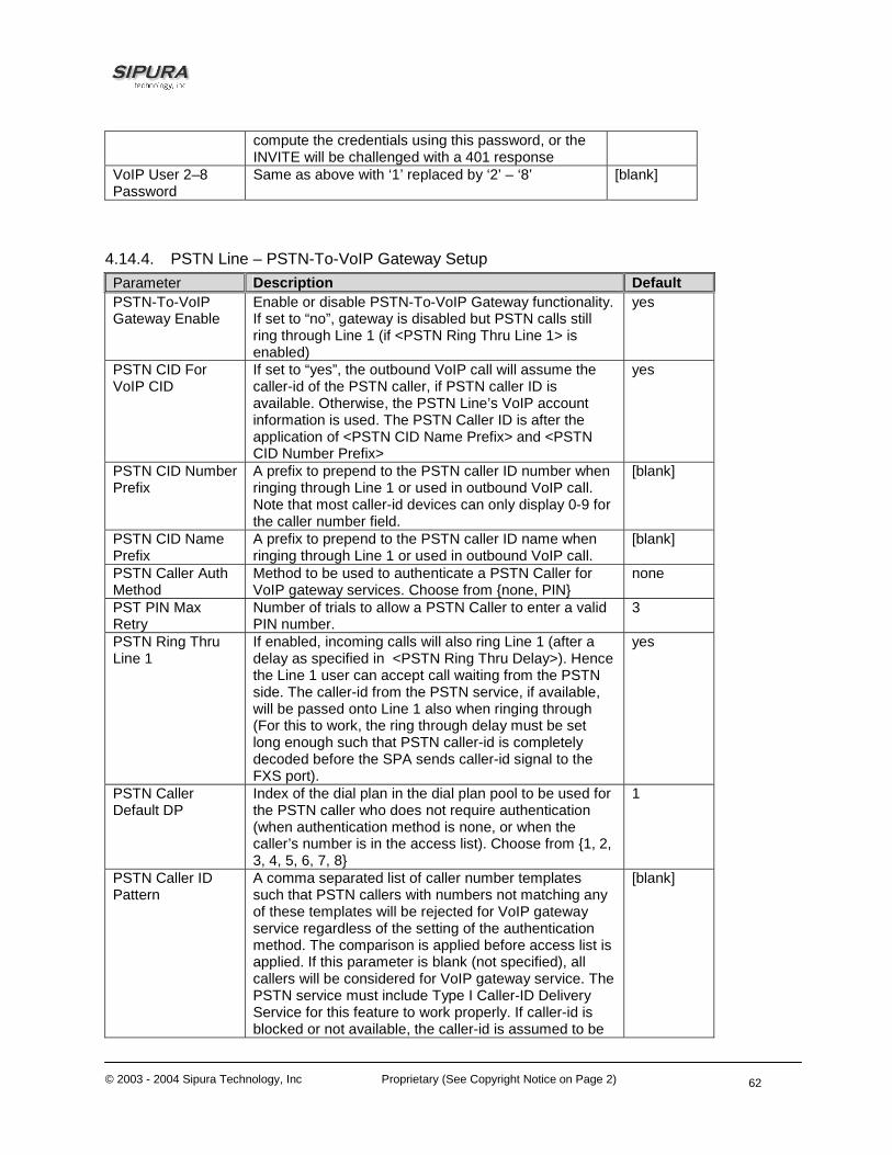
© 2003 - 2004 Sipura Technology, Inc Proprietary (See Copyright Notice on Page 2)
62
compute the credentials using this password, or the INVITE will be challenged with a 401 response
VoIP User 2–8 Password
Same as above with ‘1’ replaced by ‘2’ – ‘8’ [blank]
4.14.4. PSTN Line – PSTN-To-VoIP Gateway Setup Parameter Description Default PSTN-To-VoIP Gateway Enable
Enable or disable PSTN-To-VoIP Gateway functionality. If set to “no”, gateway is disabled but PSTN calls still ring through Line 1 (if <PSTN Ring Thru Line 1> is enabled)
yes
PSTN CID For VoIP CID
If set to “yes”, the outbound VoIP call will assume the caller-id of the PSTN caller, if PSTN caller ID is available. Otherwise, the PSTN Line’s VoIP account information is used. The PSTN Caller ID is after the application of <PSTN CID Name Prefix> and <PSTN CID Number Prefix>
yes
PSTN CID Number Prefix
A prefix to prepend to the PSTN caller ID number when ringing through Line 1 or used in outbound VoIP call. Note that most caller-id devices can only display 0-9 for the caller number field.
[blank]
PSTN CID Name Prefix
A prefix to prepend to the PSTN caller ID name when ringing through Line 1 or used in outbound VoIP call.
[blank]
PSTN Caller Auth Method
Method to be used to authenticate a PSTN Caller for VoIP gateway services. Choose from {none, PIN}
none
PST PIN Max Retry
Number of trials to allow a PSTN Caller to enter a valid PIN number.
3
PSTN Ring Thru Line 1
If enabled, incoming calls will also ring Line 1 (after a delay as specified in <PSTN Ring Thru Delay>). Hence the Line 1 user can accept call waiting from the PSTN side. The caller-id from the PSTN service, if available, will be passed onto Line 1 also when ringing through (For this to work, the ring through delay must be set long enough such that PSTN caller-id is completely decoded before the SPA sends caller-id signal to the FXS port).
yes
PSTN Caller Default DP
Index of the dial plan in the dial plan pool to be used for the PSTN caller who does not require authentication (when authentication method is none, or when the caller’s number is in the access list). Choose from {1, 2, 3, 4, 5, 6, 7, 8}
1
PSTN Caller ID Pattern
A comma separated list of caller number templates such that PSTN callers with numbers not matching any of these templates will be rejected for VoIP gateway service regardless of the setting of the authentication method. The comparison is applied before access list is applied. If this parameter is blank (not specified), all callers will be considered for VoIP gateway service. The PSTN service must include Type I Caller-ID Delivery Service for this feature to work properly. If caller-id is blocked or not available, the caller-id is assumed to be
[blank]
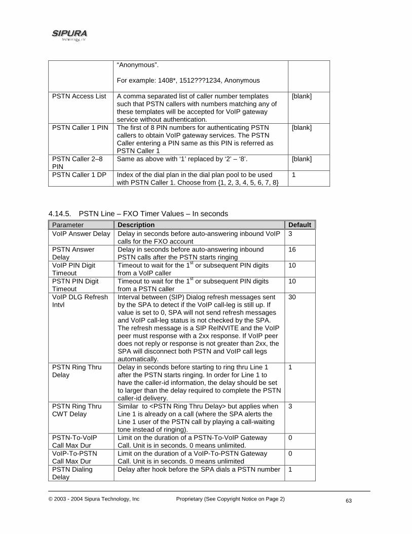
© 2003 - 2004 Sipura Technology, Inc Proprietary (See Copyright Notice on Page 2)
63
“Anonymous”. For example: 1408*, 1512???1234, Anonymous
PSTN Access List A comma separated list of caller number templates such that PSTN callers with numbers matching any of these templates will be accepted for VoIP gateway service without authentication.
[blank]
PSTN Caller 1 PIN The first of 8 PIN numbers for authenticating PSTN callers to obtain VoIP gateway services. The PSTN Caller entering a PIN same as this PIN is referred as PSTN Caller 1
[blank]
PSTN Caller 2–8 PIN
Same as above with ‘1’ replaced by ‘2’ – ‘8’. [blank]
PSTN Caller 1 DP Index of the dial plan in the dial plan pool to be used with PSTN Caller 1. Choose from {1, 2, 3, 4, 5, 6, 7, 8}
1
4.14.5. PSTN Line – FXO Timer Values – In seconds Parameter Description Default VoIP Answer Delay Delay in seconds before auto-answering inbound VoIP
calls for the FXO account 3
PSTN Answer Delay
Delay in seconds before auto-answering inbound PSTN calls after the PSTN starts ringing
16
VoIP PIN Digit Timeout
Timeout to wait for the 1st or subsequent PIN digits from a VoIP caller
10
PSTN PIN Digit Timeout
Timeout to wait for the 1st or subsequent PIN digits from a PSTN caller
10
VoIP DLG Refresh Intvl
Interval between (SIP) Dialog refresh messages sent by the SPA to detect if the VoIP call-leg is still up. If value is set to 0, SPA will not send refresh messages and VoIP call-leg status is not checked by the SPA. The refresh message is a SIP ReINVITE and the VoIP peer must response with a 2xx response. If VoIP peer does not reply or response is not greater than 2xx, the SPA will disconnect both PSTN and VoIP call legs automatically.
30
PSTN Ring Thru Delay
Delay in seconds before starting to ring thru Line 1 after the PSTN starts ringing. In order for Line 1 to have the caller-id information, the delay should be set to larger than the delay required to complete the PSTN caller-id delivery.
1
PSTN Ring Thru CWT Delay
Similar to <PSTN Ring Thru Delay> but applies when Line 1 is already on a call (where the SPA alerts the Line 1 user of the PSTN call by playing a call-waiting tone instead of ringing).
3
PSTN-To-VoIP Call Max Dur
Limit on the duration of a PSTN-To-VoIP Gateway Call. Unit is in seconds. 0 means unlimited.
0
VoIP-To-PSTN Call Max Dur
Limit on the duration of a VoIP-To-PSTN Gateway Call. Unit is in seconds. 0 means unlimited
0
PSTN Dialing Delay
Delay after hook before the SPA dials a PSTN number 1

© 2003 - 2004 Sipura Technology, Inc Proprietary (See Copyright Notice on Page 2)
64
PSTN Ring Timeout
Delay after a ring burst before the SPA decides that PSTN ring has ceased
5
4.14.6. PSTN Line – PSTN Disconnect Detection Parameter Description Default Detect CPC CPC is a brief removal of Tip-and-ring voltage. If
enabled, the SPA will disconnect both call legs when this the signal is detected during a gateway call
yes
Detect Polarity Reversal
If enabled, SPA will disconnect both call legs when this signal is detected during a gateway call. If it is a PSTN gateway call, the 1st polarity reversal is ignored and the 2nd one triggers the disconnection. For VoIP gateway call, the 1st polarity reversal triggers the disconnection.
yes
Detect PSTN Long Silence
If enabled, SPA will disconnect both call legs when the PSTN side has no voice activity for a duration longer than the length specified in <PSTN Long Silence Duration> during a gateway call
yes
Detect VoIP Long Silence
If enabled, SPA will disconnect both call legs when no RTP packets are received from the VoIP peer for a duration longer than the length specified in <VoIP Long Silence Duration> during a gateway call
yes
Detect Disconnect Tone
If enabled, SPA will disconnect both call legs when it detects the disconnect tone from the PSTN side during a gateway call. Disconnect tone is specified in the <Disconnect Tone> parameter, which depends on the PSTN service.
yes
PSTN Long Silence Duration
This is minimum length of PSTN silence (or inactivity) in seconds to trigger a gateway call disconnection if <Detect Long Silence> is “yes”
30
VoIP Long Silence Duration
This is minimum length of VoIP silence (i.e., NO-RTP-PACKETS) in seconds to trigger a gateway call disconnection if <Detect VoIP Long Silence> is “yes”
30
PSTN Silence Threshold
This parameter adjusts the sensitivity of PSTN silence detection. Choose from {very low, low, medium, high, very high}. The lower the setting, the easier to detect silence and hence easier to trigger a disconnection.
medium
Disconnect Tone This is the tone script which describes to the SPA the tone to detect as a disconnect tone. The syntax follows a standard Tone Script with some restrictions. Default value is standard US reorder (fast busy) tone, for 4 seconds. Restrictions:
1. 2 frequency components must be given. If single frequency is desired, the same frequency is used for both
2. The tone level value is not used. –30 (dBm) should be used for now.
3. Only 1 segment set is allowed 4. Total duration of the segment set is interpreted
as the minimum duration of the tone to trigger
480@-30,620@-30;4(.25/.25/1+2)

© 2003 - 2004 Sipura Technology, Inc Proprietary (See Copyright Notice on Page 2)
65
detection 5. 6 segments of on/off time (seconds) can be
specified. A 10% margin is used to validated cadence characteristics of the tone
Min CPC Duration Minimum duration (in seconds) of a low tip-and-ring voltage (below 1V) for the SPA to recognize as a CPC signal or PSTN line removal.
0.2
4.14.7. PSTN Line – International Control Parameter Description Default FXO Port Impedance
Desired impedance of the FXO Port. Choose from { 600, 900, 270+750||150nF, 220+820||120nF, 370+620||310nF, 320+1050||230nF, 370+820||110nF, 275+780||115nF, 120+820||110nF, 350+1000||210nF, 0+900||30nF, 600+2.16uF, 900+1uF, 900+2.16uF, 600+1uF, Global}
600
SPA To PSTN Gain
dB of digital gain (or attenuation if negative) to be applied to the signal sent from the SPA to the PSTN side.
0
PSTN To SPA Gain
dB of digital gain (or attenuation if negative) to be applied to the signal sent from the PSTN side to the SPA.
0
Tip/Ring Voltage Adjust
Adjust the Tip/Ring voltage on the PSTN line. Choose from {3.1V, 3.2V, 3.35V, 3.5V}
3.5
Operational Loop Current Min
Adjust the minimum loop current at which the SPA can operate. Chose from {10mA, 12mA, 14mA, 16mA}
10
On-Hook Speed Adjust the time for the loop current to drop to 0 after the SPA takes the FXO port on-hook. Choose from {Less than 0.5ms, 3ms (ETSI), 26ms (Australia)}
Less than 0.5ms
Current Limiting Enable
If enabled, it limits the loop current to a maximum of 60mA per the TBR21 standard
no
Ring Frequency Min
Lower limit of ring frequency to detect ringing signal 10
Ring Frequency Max
Upper limit of ring frequency to detect ringing signal 100
Ring Validation Time
Minimum duration of the ringing signal to be qualified as a ringing signal by the SPA. Choose from {100, 150, 200, 256, 384, 512, 640, 1024} (ms)
256ms
Ring Indication Delay in asserting a ringing signal after detecting it 512ms
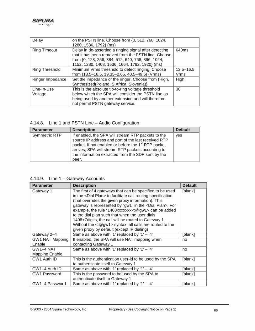
© 2003 - 2004 Sipura Technology, Inc Proprietary (See Copyright Notice on Page 2)
66
Delay on the PSTN line. Choose from {0, 512, 768, 1024, 1280, 1536, 1792} (ms)
Ring Timeout Delay in de-asserting a ringing signal after detecting that it has been removed from the PSTN line. Choose from {0, 128, 256, 384, 512, 640, 768, 896, 1024, 1152, 1280, 1408, 1536, 1664, 1792, 1920} (ms)
640ms
Ring Threshold Minimum Vrms threshold to detect ringing. Choose from {13.5–16.5, 19.35–2.65, 40.5–49.5} (Vrms)
13.5–16.5 Vrms
Ringer Impedance Set the impedance of the ringer. Choose from {High, Synthesized(Poland, S.Africa, Slovenia)}
High
Line-In-Use Voltage
This is the absolute tip-to-ring voltage threshold below which the SPA will consider the PSTN line as being used by another extension and will therefore not permit PSTN gateway service.
30
4.14.8. Line 1 and PSTN Line – Audio Configuration Parameter Description Default Symmetric RTP If enabled, the SPA will stream RTP packets to the
source IP address and port of the last received RTP packet. If not enabled or before the 1st RTP packet arrives, SPA will stream RTP packets according to the information extracted from the SDP sent by the peer.
yes
4.14.9. Line 1 – Gateway Accounts Parameter Description Default Gateway 1 The first of 4 gateways that can be specified to be used
in the <Dial Plan> to facilitate call routing specification (that overrides the given proxy information). This gateway is represented by “gw1” in the <Dial Plan>. For example, the rule “1408xxxxxxx<:@gw1> can be added to the dial plan such that when the user dials 1408+7digits, the call will be routed to Gateway 1. Without the <:@gw1> syntax, all calls are routed to the given proxy by default (except IP dialing)
[blank]
Gateway 2–4 Same as above with ‘1’ replaced by ‘1’ – ‘4’ [blank] GW1 NAT Mapping Enable
If enabled, the SPA will use NAT mapping when contacting Gateway 1
no
GW1–4 NAT Mapping Enable
Same as above with ‘1’ replaced by ‘1’ – ‘4’ no
GW1 Auth ID This is the authentication user-id to be used by the SPA to authenticate itself to Gateway 1
[blank]
GW1–4 Auth ID Same as above with ‘1’ replaced by ‘1’ – ‘4’ [blank] GW1 Password This is the password to be used by the SPA to
authenticate itself to Gateway 1 [blank]
GW1–4 Password Same as above with ‘1’ replaced by ‘1’ – ‘4’ [blank]

© 2003 - 2004 Sipura Technology, Inc Proprietary (See Copyright Notice on Page 2)
67
4.14.10. Line 1 – VoIP Fallback To PSTN Parameter Description Default Auto PSTN Fallbak If enabled, the SPA will automatically route all calls to
the PSTN gateway when the Line 1 proxy is down (registration failure or network link down).
yes
4.14.11. Line 1 – Dial Plan Parameter Description Default Dial Plan The dial plan syntax is expanded in the SPA-3000 to
allow the specification of 3 parameters to be used with a certain gateway:
1. uid – the authentication user-id, 2. pwd – the authentication password, and 3. nat – if this parameter is present, use NAT
mapping Each parameter is separated by a semi-colon (;). Furthermore, it recognizes “gw0”, “gw1”, …, “gw4” as the locally configured gateways, where “gw0” represents the local PSTN gateway in the same SPA-3000 unit. Example 1: “*1xxxxxxxxxx<:@fwdnat.pulver.com:5082;uid=jsmith;pwd=xyz” Example 2: “*1xxxxxxxxxx<:@fwd.pulver.com;nat;uid=jsmith;pwd=xyz” Example 3: “[39]11<:@gw0>
[blank]
4.14.12. User1 – Call Forward Settings Parameter Description Default Cfwd All Dest In addition to normal call forward destination as used
in the SPA-1000 and SPA-2000, one can specify in the SPA-3000:
1. gw0 – forward the caller to use the PSTN gateway
2. PSTN-number@gw0 – forward to caller to the PSTN number (dialed automatically by the SPA through the PSTN gateway)
[blank]
Cfwd Busy Dest Same as above [blank] Cfwd No Ans Dest Same as above [blank]

© 2003 - 2004 Sipura Technology, Inc Proprietary (See Copyright Notice on Page 2)
68
4.14.13. User1 – Selective Call Forward Settings Parameter Description Default Cfwd Sel1 Dest Same as Cfwd All Dest [blank] Cfwd Sel2–8 Dest Same as Cfwd All Dest [blank] Cfwd Last Dest Same as Cfwd All Dest [blank]
4.14.14. Regional – Call Progress Tones Parameter Description Default VoIP PIN Tone Specification of the tone played to prompt a VoIP caller
for a PIN number (if PIN authentication is selected and the caller requires authentication to use the PSTN gateway)
600@-10;*(0/1/1,.1/.1/1,.1/.1/1,.1/.5/1)
PSTN PIN Tone Specification of the tone played to prompt a PSTN caller for a PIN number (if PIN authentication is selected and the caller requires authentication to use the VoIP gatway)
600@-10;*(0/.7/1,.2/.1/1,.2/.1/1,.2/.5/1)
4.14.15. PSTN User – PSTN-To-VoIP Selective Call Forward Settings Parameter Description Default Cfwd Sel1 Caller First of 8 PSTN Caller Number Patterns to be blocked
for VoIP gateway services or forwarded to a certain VoIP number. If the caller is blocked, the SPA will not auto-answers the call. If the caller is forwarded, SPA will skip authentication
Cfwd Sel2-8 Caller Same as above with 1 replaced with ‘2’ – ‘8’ Cfwd Sel1 Dest VoIP destination to forward a PSTN caller matching
<Cfwd Sel1 Caller>. If this entry is [blank], the PSTN caller is blocked for VoIP service.
Cfwd Sel2-8 Dest Same as above with 1 replaced with ‘2’ – ‘8’ 4.14.16. PSTN User – PSTN-To-VoIP Speed Dial Settings Parameter Description Default Speed Dial 2 The VoIP number to call when the PSTN caller dials a
single digit ‘2’
Speed Dial 3-9 Same as above with ‘2’ replaced with ‘3’ – ‘9’ 4.14.17. PSTN User – PSTN Ring Thru Line 1 Distinctive Ring Settings Parameter Description Default Ring1 Caller First of 8 PSTN Caller Number Patterns such that the
corresponding ring will be used to ring through Line 1 if the PSTN caller matches this pattern.
Ring2-8 Caller Same as above with ‘1’ replaced with ‘2’ – ‘8’

© 2003 - 2004 Sipura Technology, Inc Proprietary (See Copyright Notice on Page 2)
69
4.14.18. PSTN User – PSTN Ring Thru Line 1 Ring Settings Parameter Description Default Default Ring The default ring to be used to ring through Line 1.
Choose from {1,2,3,4,5,6,7,8,Follow Line 1}. If “Follow Line 1” is selected, the ring to be used is determined by Line 1’s distinctive ring settings.
1
4.14.19. Info – PSTN Line Status State Parameters Description Hook State Hook state of the FXO port. Either On or Off Line Voltage Tip-to-Ring Voltage at the FXO port Loop Current Loop current to the FXO port Last Called VoIP Number The last VoIP number called from the PSTN Line Last VoIP Caller The last VoIP caller to the PSTN Line
Last PSTN Disconnect Reason
Reason for SPA hanging up the FXO port. Can be one of the following: • PSTN Disconnect Tone • PSTN Activity Timeout • CPC Signal • Polarity Reversal • VoIP Call Failed • VoIP Call Ended • Invalid VoIP Destination • Invalid PIN • PIN Digit Timeout • VoIP Dialing Timeout • PSTN Gateway Call Timeout • VoIP Gateway Call Timeout • VoIP Activity Timeout
Last Called PSTN Number The PSTN number dialed by the SPA (logged only if a non-trivial dial plan is used)
Last PSTN Caller Name and number of the last PSTN caller
PSTN Activity Timer Shows the time (ms) before the SPA disconnects the current gateway unless the PSTN side has some audio activity.
Call Type
May take one of the following values: PSTN Gateway Call = VoIP-To-PSTN Call (#4) VoIP Gateway Call = PSTN-To-VoIP Call (#3) PSTN To Line 1 = PSTN call ring through and answered by Line 1 (#6) Line 1 Forward to PSTN Gateway = VoIP calls Line 1 then forwarded to PSTN GW (#5) Line 1 Forward to PSTN Number =VoIP calls Line 1 then forwarded to PSTN number (#5) Line 1 To PSTN Gateway (#7) Line 1 Fallback To PSTN Gateway (#7)
PSTN State
May take one of the following values: - Idle - Collecting PSTN PIN - Invalid PSTN PIN

© 2003 - 2004 Sipura Technology, Inc Proprietary (See Copyright Notice on Page 2)
70
- PSTN Caller Accepted - Connected to PSTN - PSTN Offhook/VoIP Ended
PSTN Tone Indicate what tone is being played to the PSTN call leg PSTN Peer Name Name of the party at the PSTN call leg PSTN Peer Number Phone number of the party at the PSTN call leg VoIP State Same as Line 1 Call 1 Mapped SIP Port Same as Line 1 Registration State Same as Line 1 Last Registration At Same as Line 1 Next Registration In Same as Line 1
VoIP Tone Same as Line 1 Call 1 (Indicate what tone is being played to the VoIP call leg)
VoIP Peer Name Same as Line 1 Call 1 (Name of the party at the VoIP call leg) VoIP Peer Number Same as Line 1 Cal 1 (Phone number of the party at the VoIP call leg) VoIP Call Encoder Same as Line 1 Call 1 (Audio encoder being used for the VoIP call leg) VoIP Call Decoder Same as Line 1 Call 1 (Audio decoder being used for the VoIP call leg) VoIP Call FAX Same as Line 1 Call 1 VoIP Call Remote Hold Same as Line 1 Call 1 VoIP Call Duration Same as Line 1 Call 1 VoIP Call Packets Sent Same as Line 1 Call 1 VoIP Call Packets Recv Same as Line 1 Call 1 VoIP Call Bytes Sent Same as Line 1 Call 1 VoIP Call Bytes Recv Same as Line 1 Call 1 VoIP Call Decode Latency Same as Line 1 Call 1 VoIP Call Jitter Same as Line 1 Call 1 VoIP Call Round Trip Delay Same as Line 1 Call 1 VoIP Call Packets Lost Same as Line 1 Call 1 VoIP Call Packet Error Same as Line 1 Call 1 VoIP Call Mapped RTP Port Same as Line 1 Call 1 4.14.20. PSTN/VoIP Caller Commands via DTMF Command Description **# Disconnect the PSTN line (SPA will take the FXO port on-hook) **1 End the current call and restarts dial tone
5. User Guidelines The SPA can be configured to the custom requirements of the service provider, so that from the subscriber’s point of view, the service behaves exactly as the service provider wishes – with varying degrees of control left with the end user. This means that a service provider can leverage the programmability of the SPA to offer sometimes subtle yet continually valuable and differentiated services optimized for the network environment or target market(s).

© 2003 - 2004 Sipura Technology, Inc Proprietary (See Copyright Notice on Page 2)
71
This section of the Administration Guide, describes how some of the supported basic and enhanced, or supplementary services could be implemented. The implementations described below by no means are the only way to achieve the desired service behavior.
To understand the specific implementation options of the below features, including parameters, requirements and contingencies please refer the section Configuration Parameters, section 0.
5.1. Basic Services 5.1.1. Originating a Phone Call
Service Description Placing telephone a call to another telephone or telephony system (IVR, conference bridge, etc.). This is the most basic service.
User Action Required to Activate or Use When the user picks up the handset, the SPA provides dial tone and is ready to collect dialing information via DTMF digits from the telephone Touchtone key pad.
Expected Call and Network Behavior While it is possible to support overlapped dialing within the context of SIP, the SPA collects a complete phone number and sends the full number in a SIP INVITE message to the proxy server for further call processing. In order to minimize dialing delay, the SPA maintains a dial plan and matches it against the cumulative number entered by the user. The SPA also detects invalid phone numbers not compatible with the dial plan and alerts the user via a configurable tone (Reorder) or announcement.
User Action Required to Deactivate or End Hang-up the telephone.
5.1.2. Receiving a Phone Call
Service Description The SPA can receive calls from the PSTN or other IP Telephony subscribers
User Action Required to Activate or Use When the telephone rings, pick up the handset and begin talking.
Expected Call and Network Behavior Each subscriber is assigned an E.164 ID (phone number) so that they may be reached from wired or wireless callers on the PSTN or IP network. The SPA supplies ring voltage to the attached telephone set to alert the user of incoming calls.
User Action Required to Deactivate or End Hang-up the telephone.
5.2. Enhanced Services

© 2003 - 2004 Sipura Technology, Inc Proprietary (See Copyright Notice on Page 2)
72
5.2.1. Caller ID
Service Description If available, the SPA supports the generation and pass through of Caller ID information.
User Action Required to Activate or Use No user action required. The user’s telephone equipment must support Caller ID to display the caller’s name and/or number.
Expected Call and Network Behavior In between ringing bursts, the SPA can generate a Caller-ID signal to the attached phone when the phone is on-hook.
As part of the INVITE message, the SPA sends the caller’s name and number as it is configured in the profile.
User Action Required to Deactivate or End No user action required. See CLIP and CLIR.
5.2.2. Calling Line Identification Presentation (CLIP)
Service Description Some users will elect to block their Caller ID information for all outgoing calls. However, there may be circumstances where sending Caller ID information for a call is desired, i.e. trying to reach a party that does not accept Caller ID blocked calls.
User Action Required to Activate or Use Lift the receiver
Listen for dial tone
Press *__
Listen for dial tone
Dial the telephone number you are calling
Expected Call and Network Behavior Caller ID will be sent to the distant party for this call only. Users must repeat this process at the start of each call.
User Action Required to Deactivate or End No action required. This service is only in effect for the duration of the current call.
5.2.3. Calling Line Identification Restriction (CLIR) – Caller ID Blocking
Service Description This feature allows the user to block the delivery of their Caller ID to the number they are calling. This feature must be activated prior to dialing each call and is only in effect for the duration of each call.

© 2003 - 2004 Sipura Technology, Inc Proprietary (See Copyright Notice on Page 2)
73
User Action Required to Activate or Use Lift the receiver
Listen for dial tone
Press *__
Listen for dial tone
Dial the telephone number you are calling
You must repeat this process at the start of each call
Expected Call and Network Behavior The user activates this service to hide his Caller ID when making an outgoing call.
User Action Required to Deactivate or End No action required. This service is only in effect for the duration of the current call.
5.2.4. Call Waiting
Service Description The user can accept a call from a 3rd party while engaging in an active call. The SPA shall alert the subscriber of the 2nd incoming call by playing a call waiting tone.
User Action Required to Activate or Use If the you choose to answer the second call either:
Press and release your phone's switch hook (the button you release when you take your phone off the hook) or
Press the flash button (if your phone has one).
This puts your first call on hold and automatically connects you to your second call.
To put your second caller back on hold and return to your first caller, press the switch hook or flash button again. (You can alternate between calls as often as you like.)
Expected Call and Network Behavior If the user is on a call when another call comes in they will hear a series of beeps / tones alerting them to the second call. The person calling will hear normal ringing.
User Action Required to Deactivate or End See Cancel Call Waiting.
5.2.5. Disable or Cancel Call Waiting
Service Description The SPA supports disabling of call waiting permanently or on a per call basis.
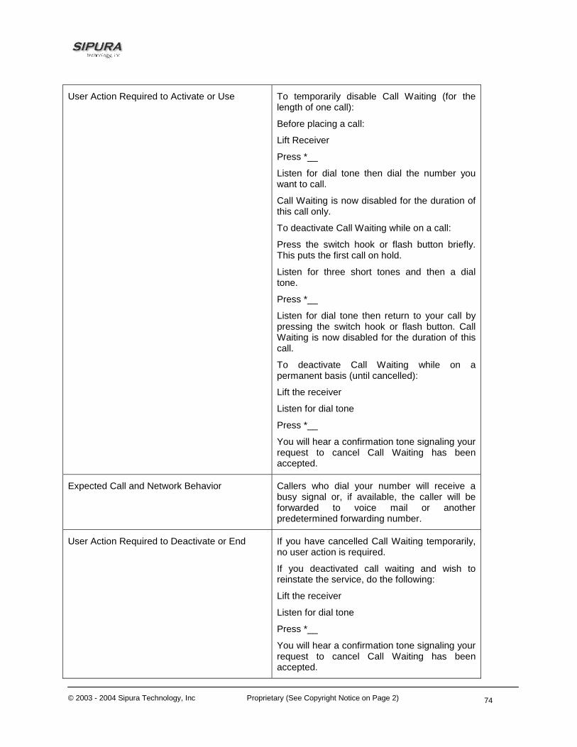
© 2003 - 2004 Sipura Technology, Inc Proprietary (See Copyright Notice on Page 2)
74
User Action Required to Activate or Use To temporarily disable Call Waiting (for the length of one call):
Before placing a call:
Lift Receiver
Press *__
Listen for dial tone then dial the number you want to call.
Call Waiting is now disabled for the duration of this call only.
To deactivate Call Waiting while on a call:
Press the switch hook or flash button briefly. This puts the first call on hold.
Listen for three short tones and then a dial tone.
Press *__
Listen for dial tone then return to your call by pressing the switch hook or flash button. Call Waiting is now disabled for the duration of this call.
To deactivate Call Waiting while on a permanent basis (until cancelled):
Lift the receiver
Listen for dial tone
Press *__
You will hear a confirmation tone signaling your request to cancel Call Waiting has been accepted.
Expected Call and Network Behavior Callers who dial your number will receive a busy signal or, if available, the caller will be forwarded to voice mail or another predetermined forwarding number.
User Action Required to Deactivate or End If you have cancelled Call Waiting temporarily, no user action is required.
If you deactivated call waiting and wish to reinstate the service, do the following:
Lift the receiver
Listen for dial tone
Press *__
You will hear a confirmation tone signaling your request to cancel Call Waiting has been accepted.
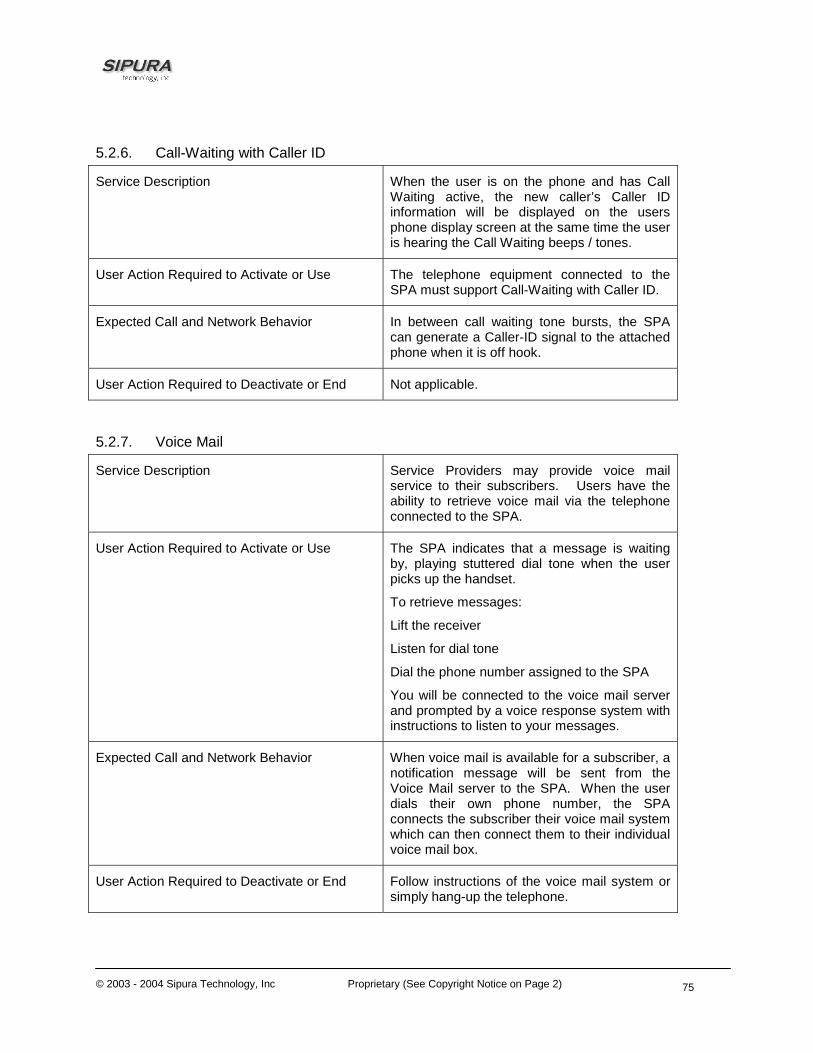
© 2003 - 2004 Sipura Technology, Inc Proprietary (See Copyright Notice on Page 2)
75
5.2.6. Call-Waiting with Caller ID
Service Description When the user is on the phone and has Call Waiting active, the new caller’s Caller ID information will be displayed on the users phone display screen at the same time the user is hearing the Call Waiting beeps / tones.
User Action Required to Activate or Use The telephone equipment connected to the SPA must support Call-Waiting with Caller ID.
Expected Call and Network Behavior In between call waiting tone bursts, the SPA can generate a Caller-ID signal to the attached phone when it is off hook.
User Action Required to Deactivate or End Not applicable.
5.2.7. Voice Mail
Service Description Service Providers may provide voice mail service to their subscribers. Users have the ability to retrieve voice mail via the telephone connected to the SPA.
User Action Required to Activate or Use The SPA indicates that a message is waiting by, playing stuttered dial tone when the user picks up the handset.
To retrieve messages:
Lift the receiver
Listen for dial tone
Dial the phone number assigned to the SPA
You will be connected to the voice mail server and prompted by a voice response system with instructions to listen to your messages.
Expected Call and Network Behavior When voice mail is available for a subscriber, a notification message will be sent from the Voice Mail server to the SPA. When the user dials their own phone number, the SPA connects the subscriber their voice mail system which can then connect them to their individual voice mail box.
User Action Required to Deactivate or End Follow instructions of the voice mail system or simply hang-up the telephone.

© 2003 - 2004 Sipura Technology, Inc Proprietary (See Copyright Notice on Page 2)
76
5.2.8. Attendant Call Transfer
Service Description Attendant Call Transfer lets a customer use their Touchtone phone to send a call to any other phone, inside or outside their business, including a wireless phones.
User Action Required to Activate or Use While in a call with the party to be transferred:
Press the switch hook or flash button on the phone to place the party on hold
Listen for three short tones followed by dial tone
Dial the number to which you will transfer the caller
Stay on the line until the called number answers
Announce the call
Press the switch hook or flash button adding the held party to the call
Hang up to connect the two parties and transfer the call
Note: You can hook flash while the 3rd party is ringing to start an early conference. Then hang up to complete the transfer without waiting for the 3rd party to answer first.
Expected Call and Network Behavior When the user presses the switch hook or flash button, the transferee is placed on hold. When the user successfully dials the transfer number and the party answers the transferee can be added to the call by pressing the switch hook or flash button creating a three-way conference. When the user hangs up the phone the transferee and the called party remain in a call.
User Action Required to Deactivate or End Not applicable.
5.2.9. Unattended or “Blind” Call Transfer
Service Description Unattended or “Blind” Call Transfer lets a customer use their Touchtone phone to send a call to any other phone, inside or outside their business, including a wireless phones.
User Action Required to Activate or Use While in a call with the party to be transferred:
Press the switch hook or flash button on the
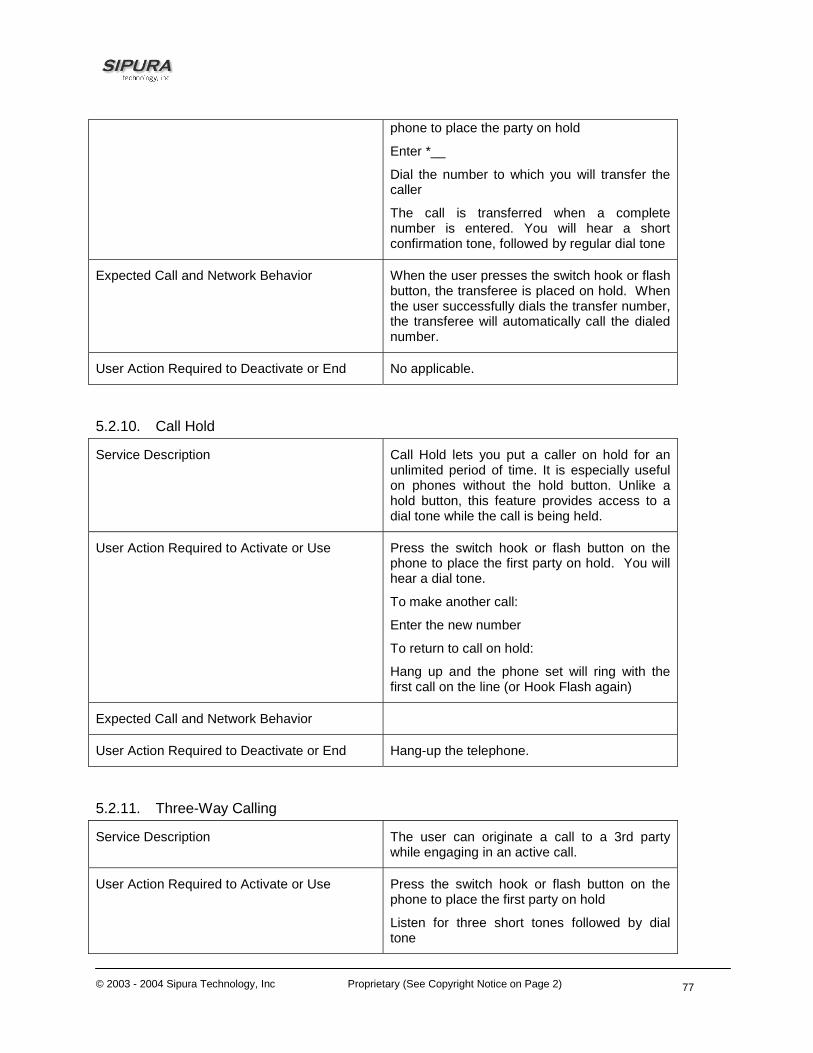
© 2003 - 2004 Sipura Technology, Inc Proprietary (See Copyright Notice on Page 2)
77
phone to place the party on hold
Enter *__
Dial the number to which you will transfer the caller
The call is transferred when a complete number is entered. You will hear a short confirmation tone, followed by regular dial tone
Expected Call and Network Behavior When the user presses the switch hook or flash button, the transferee is placed on hold. When the user successfully dials the transfer number, the transferee will automatically call the dialed number.
User Action Required to Deactivate or End No applicable.
5.2.10. Call Hold
Service Description Call Hold lets you put a caller on hold for an unlimited period of time. It is especially useful on phones without the hold button. Unlike a hold button, this feature provides access to a dial tone while the call is being held.
User Action Required to Activate or Use Press the switch hook or flash button on the phone to place the first party on hold. You will hear a dial tone.
To make another call:
Enter the new number
To return to call on hold:
Hang up and the phone set will ring with the first call on the line (or Hook Flash again)
Expected Call and Network Behavior
User Action Required to Deactivate or End Hang-up the telephone.
5.2.11. Three-Way Calling
Service Description The user can originate a call to a 3rd party while engaging in an active call.
User Action Required to Activate or Use Press the switch hook or flash button on the phone to place the first party on hold
Listen for three short tones followed by dial tone

© 2003 - 2004 Sipura Technology, Inc Proprietary (See Copyright Notice on Page 2)
78
Dial the number of the 3rd party.
When the 3rd party answers you may have a conversation with them while the other party is on hold.
To hold a conference with the party on hold and the 3rd party, simply press the switch hook or flash button
Expected Call and Network Behavior The SPA supports up to two calls per line. The SPA can conference two calls by bridging the 2nd and 3rd parties.
User Action Required to Deactivate or End Hang-up the telephone.
5.2.12. Three-Way Ad-Hoc Conference Calling
Service Description This feature allows the user to conference up to two other numbers on the same line to create a three-way call.
User Action Required to Activate or Use If you are already on a call and wish to add a third party:
Press the switch hook or flash button
Listen for dial tone
Dial the third party normally
When the third party number starts to ring press the switch hook or flash button again
You now have the original caller and the third party together with you on the same call.
If you want to initiate a new Three Way Call:
Call the first party in the normal manner
Follow the directions for adding a third party (see instructions above)
Expected Call and Network Behavior The SPA can host a 3-way conference and perform 3-way audio mixing (without the need of an external conference bridge device or service).
If you also have Call Transfer you can also hang up at any time to transfer the original caller to the third party
User Action Required to Deactivate or End
5.2.13. Call Return

© 2003 - 2004 Sipura Technology, Inc Proprietary (See Copyright Notice on Page 2)
79
Service Description The SPA supports a service that allows the SPA to automatically dial the last caller’s number.
User Action Required to Activate or Use Pick up the receiver
Listen for dial tone
Press *__ to dial back the last caller that tried to reach you.
Expected Call and Network Behavior This service gives the user the convenience of recalling the last incoming call to their number automatically.
User Action Required to Deactivate or End No user action required
5.2.14. Automatic Call Back
Service Description This feature allows the user to place a call to the last number they tried to reach whether the call was answered, unanswered or busy by dialing an activation code.
User Action Required to Activate or Use Pick up the receiver
Listen for dial tone
Press *__
Expected Call and Network Behavior If the number called is idle the call will ring through and complete normally. If the called number is busy the user will hear a special announcement and the feature will monitor the called number for up to 30 minutes. When both lines are idle, the user hears a special ring.
During the monitoring process the user can continue to originate and receive calls without affecting the Call Return on Busy request. Call Return on Busy requests can be canceled by dialing the deactivation code.
User Action Required to Deactivate or End Lift the receiver
Listen for dial tone
Press *__
5.2.15. Call FWD – Unconditional
Service Description All calls are immediately forwarded to the designated forwarding number. The SPA will

© 2003 - 2004 Sipura Technology, Inc Proprietary (See Copyright Notice on Page 2)
80
not ring or provide call waiting when Call FWD – Unconditional is activated.
User Action Required to Activate or Use Lift the receiver
Listen for dial tone
Press *__
Listen for dial tone and enter the telephone number you are forwarding your call to.
Activation will be confirmed with three short bursts of tone and your forwarding will be activated.
Alternatively, the user can activate this feature from a web browser interface.
Expected Call and Network Behavior This feature allows a user the option to divert (forward) all calls to their telephone number to any number using the touchtone keypad of their telephone or web browser interface. This service is activated or deactivated from the phone being forwarded or the web browser interface.
User Action Required to Deactivate or End Lift the receiver
Listen for dial tone
Press *__
You will hear a confirmation tone signaling your change has been accepted.
Alternatively, the user can deactivate this feature from a web browser interface.
5.2.16. Call FWD – Busy
Service Description Calls are forwarded to the designated forwarding number if the subscriber’s line is busy because of the following; Primary line already in a call, primary and secondary line in a call or conference.
User Action Required to Activate or Use Lift the receiver
Listen for dial tone
Press *__
Listen for dial tone and enter the telephone number you are forwarding your call to.
Activation will be confirmed with three short bursts of tone and your forwarding will be
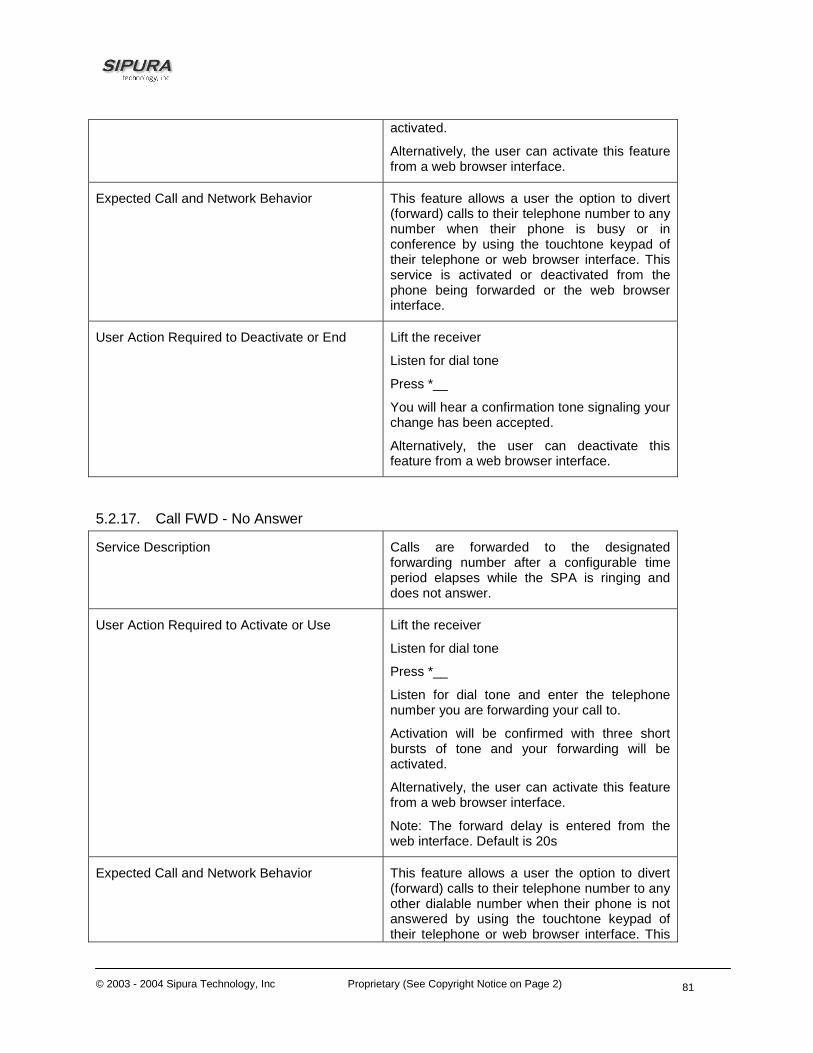
© 2003 - 2004 Sipura Technology, Inc Proprietary (See Copyright Notice on Page 2)
81
activated.
Alternatively, the user can activate this feature from a web browser interface.
Expected Call and Network Behavior This feature allows a user the option to divert (forward) calls to their telephone number to any number when their phone is busy or in conference by using the touchtone keypad of their telephone or web browser interface. This service is activated or deactivated from the phone being forwarded or the web browser interface.
User Action Required to Deactivate or End Lift the receiver
Listen for dial tone
Press *__
You will hear a confirmation tone signaling your change has been accepted.
Alternatively, the user can deactivate this feature from a web browser interface.
5.2.17. Call FWD - No Answer
Service Description Calls are forwarded to the designated forwarding number after a configurable time period elapses while the SPA is ringing and does not answer.
User Action Required to Activate or Use Lift the receiver
Listen for dial tone
Press *__
Listen for dial tone and enter the telephone number you are forwarding your call to.
Activation will be confirmed with three short bursts of tone and your forwarding will be activated.
Alternatively, the user can activate this feature from a web browser interface.
Note: The forward delay is entered from the web interface. Default is 20s
Expected Call and Network Behavior This feature allows a user the option to divert (forward) calls to their telephone number to any other dialable number when their phone is not answered by using the touchtone keypad of their telephone or web browser interface. This

© 2003 - 2004 Sipura Technology, Inc Proprietary (See Copyright Notice on Page 2)
82
service is activated or deactivated from the phone being forwarded or the web browser interface.
User Action Required to Deactivate or End Lift the receiver
Listen for dial tone
Press *__
You will hear a confirmation tone signaling your change has been accepted.
Alternatively, the user can deactivate this feature from a web browser interface.
5.2.18. Anonymous Call Blocking
Service Description By setting the corresponding configuration parameter on the SPA, the subscriber has the option to block incoming calls that do not reveal the caller’s Caller ID.
User Action Required to Activate or Use Pick up the receiver
Listen for dial tone
To Activate Press *__
Expected Call and Network Behavior When activated by the user, callers will hear (busy) tone.
User Action Required to Deactivate or End To De-activate Press *__
5.2.19. Distinctive / Priority Ringing and Call Waiting Tone
Service Description The SPA supports a number of ringing and call waiting tone patterns to be played when incoming calls arrive. The choice of alerting pattern to use is carried in the incoming SIP INVITE message inserted by the SIP Proxy Server (or other intermediate application server in the Service Provider’s domain).
User Action Required to Activate or Use Pick up the receiver
Listen for dial tone
Press *__
Expected Call and Network Behavior With this service, incoming calls from up to __ telephone numbers can be automatically identified by distinctive ringing. A distinctive ringing pattern (i.e. short-long-short)
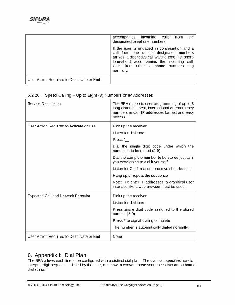
© 2003 - 2004 Sipura Technology, Inc Proprietary (See Copyright Notice on Page 2)
83
accompanies incoming calls from the designated telephone numbers.
If the user is engaged in conversation and a call from one of the designated numbers arrives, a distinctive call waiting tone (i.e. short-long-short) accompanies the incoming call. Calls from other telephone numbers ring normally.
User Action Required to Deactivate or End
5.2.20. Speed Calling – Up to Eight (8) Numbers or IP Addresses
Service Description The SPA supports user programming of up to 8 long distance, local, international or emergency numbers and/or IP addresses for fast and easy access.
User Action Required to Activate or Use Pick up the receiver
Listen for dial tone
Press *__
Dial the single digit code under which the number is to be stored (2-9)
Dial the complete number to be stored just as if you were going to dial it yourself
Listen for Confirmation tone (two short beeps)
Hang up or repeat the sequence
Note: To enter IP addresses, a graphical user interface like a web browser must be used.
Expected Call and Network Behavior Pick up the receiver
Listen for dial tone
Press single digit code assigned to the stored number (2-9)
Press # to signal dialing complete
The number is automatically dialed normally.
User Action Required to Deactivate or End None
6. Appendix I: Dial Plan The SPA allows each line to be configured with a distinct dial plan. The dial plan specifies how to interpret digit sequences dialed by the user, and how to convert those sequences into an outbound dial string.

© 2003 - 2004 Sipura Technology, Inc Proprietary (See Copyright Notice on Page 2)
84
The SPA syntax for the dial plan closely resembles the corresponding syntax specified by MGCP and MEGACO. Some extensions are added that are useful in an end-point. The dial plan functionality is regulated by the following configurable parameters: • Interdigit_Long_Timer • Interdigit_Short_Timer • Dial_Plan ([1] and [2]) Other timers are configurable via parameters, but do not directly pertain to the dial plan itself. They are discussed elsewhere in this document. Interdigit Long Timer: ParName: Interdigit_Long_Timer
Default: 10
The Interdigit_Long_Timer specifies the default maximum time (in seconds) allowed between dialed digits, when no candidate digit sequence is as yet complete (see discussion of Dial_Plan parameter for an explanation of candidate digit sequences). Interdigit Short Timer: ParName: Interdigit_Short_Timer
Default: 3
The Interdigit_Short_Timer specifies the default maximum time (in seconds) allowed between dialed digits, when at least one candidate digit sequence is complete as dialed (see discussion of Dial_Plan parameter for an explanation of candidate digit sequences). Dial Plan[1] and Dial Plan[2]: ParName: Dial_Plan[1] and Dial_Plan[2]
Default: ( *xx | [3469]11 | 0 | 00 | <:1408>[2-9]xxxxxx | 1[2-9]xx[2-9]xxxxxx | 011x. )
The Dial_Plan parameters contain the actual dial plan scripts for each of lines 1 and 2. Dial Plan Digit Sequences: The plans contain a series of digit sequences, separated by the ‘|’ character. The collection of sequences is enclosed in parentheses, ‘(‘ and ‘)’. When a user dials a series of digits, each sequence in the dial plan is tested as a possible match. The matching sequences form a set of candidate digit sequences. As more digits are entered by the user, the set of candidates diminishes until only one or none are valid.

© 2003 - 2004 Sipura Technology, Inc Proprietary (See Copyright Notice on Page 2)
85
Any one of a set of terminating events triggers the SPA to either accept the user-dialed sequence, and transmit it to initiate a call, or else reject it as invalid. The terminating events are: • No candidate sequences remain: the number is rejected. • Only one candidate sequence remains, and it has been matched completely: the number is
accepted and transmitted after any transformations indicated by the dial plan, unless the sequence is barred by the dial plan (barring is discussed later), in which case the number is rejected.
• A timeout occurs: the digit sequence is accepted and transmitted as dialed if incomplete, or transformed as per the dial plan if complete.
• An explicit ‘send’ (user presses the ‘#’ key): the digit sequence is accepted and transmitted as dialed if incomplete, or transformed as per the dial plan if complete.
The timeout duration depends on the matching state. If no candidate sequences are as yet complete (as dialed), the Interdigit_Long_Timeout applies. If a candidate sequence is complete, but there exists one or more incomplete candidates, then the Interdigit_Short_Timeout applies. White space is ignored, and may be used for readability.
Digit Sequence Syntax:
Each digit sequence within the dial plan consists of a series of elements, which are individually matched to the keys pressed by the user. Elements can be one of the following: • Individual keys ‘0’, ‘1’, ‘2’ . . . ‘9’, ‘*’, ‘#’. • The letter ‘x’ matches any one numeric digit (‘0’ .. ‘9’) • A subset of keys within brackets (allows ranges): ‘[‘ set ‘]’ (e.g. [389] means ‘3’ or ‘8’ or ‘9’)
o Numeric ranges are allowed within the brackets: digit ‘-‘ digit (e.g. [2-9] means ‘2’ or ‘3’ or … or ‘9’)
o Ranges can be combined with other keys: e.g. [235-8*] means ‘2’ or ‘3’ or ‘5’ or ‘6’ or ‘7’ or ‘8’ or ‘*’.
Element repetition:
Any element can be repeated zero or more times by appending a period (‘.’ character) to the element. Hence, “01.” matches “0”, “01”, “011”, “0111”, … etc.
Subsequence Substitution:
A subsequence of keys (possibly empty) can be automatically replaced with a different subsequence using an angle bracket notation: ‘<’ dialed-subsequence ‘:’ transmitted-subsequence ‘>’. So, for example, “<8:1650>xxxxxxx” would match “85551212” and transmit “16505551212”.
Intersequence Tones:
An “outside line” dial tone can be generated within a sequence by appending a ‘,’ character between digits. Thus, the sequence “9, 1xxxxxxxxxx” sounds an “outside line” dial tone after the user presses ‘9’, until the ‘1’ is pressed.
Number Barring:
A sequence can be barred (rejected) by placing a ‘!’ character at the end of the sequence. Thus, “1900xxxxxxx!” automatically rejects all 900 area code numbers from being dialed.

© 2003 - 2004 Sipura Technology, Inc Proprietary (See Copyright Notice on Page 2)
86
Interdigit Timer Master Override:
The long and short interdigit timers can be changed in the dial plan (affecting a specific line) by preceding the entire plan with the following syntax: • Long interdigit timer: ‘L’ ‘:’ delay-value ‘,’ • Short interdigit timer: ‘S’ ‘:’ delay-value ‘,’ Thus, “L=8,( . . . )” would set the interdigit long timeout to 8 seconds for the line associated with this dial plan. And, “L:8,S:4,( . . . )” would override both the long and the short timeout values.
Local Timer Overrides:
The long and short timeout values can be changed for a particular sequence starting at a particular point in the sequence. The syntax for long timer override is: ‘L’ delay-value ‘ ‘. Note the terminating space character. The specified delay-value is measured in seconds. Similarly, to change the short timer override, use: ‘S’ delay-value <space>.
Pause:
A sequence may require an explicit pause of some duration before continuing to dial digits, in order for the sequence to match. The syntax for this is similar to the timer override syntax: ‘P’ delay-value <space>. The delay-value is measured in seconds.
This syntax allows for the implementation of Hot-Line and Warm-Line services. To achieve this, one sequence in the plan must start with a pause, with a 0 delay for a Hot Line, and a non-zero delay for a Warm Line.
Implicit sequences:
The SPA implicitly appends the vertical code sequences entered in the Regional parameter settings to the end of the dial plan for both line 1 and line 2. Likewise, if Enable_IP_Dialing is enabled, then ip dialing is also accepted on the associated line.
Examples:
The following dial plan accepts only US-style 1 + area-code + local-number, with no restrictions on the area code and number.
( 1 xxx xxxxxxx )
The following also allows 7-digit US-style dialing, and automatically inserts a 1 + 212 (local area code) in the transmitted number.
( 1 xxx xxxxxxx | <:1212> xxxxxxx )
For an office environment, the following plan requires a user to dial 8 as a prefix for local calls and 9 as a prefix for long distance. In either case, an “outside line” tone is played after the initial 8 or 9, and neither prefix is transmitted when initiating the call.

© 2003 - 2004 Sipura Technology, Inc Proprietary (See Copyright Notice on Page 2)
87
( <9,:> 1 xxx xxxxxxx | <8,:1212> xxxxxxx )
The following allows only placing international calls (011 call), with an arbitrary number of digits past a required 5 digit minimum, and also allows calling an international call operator (00). In addition, it lengthens the default short interdigit timeout to 4 seconds.
S:4, ( 00 | 011 xxxxx x. )
The following allows only US-style 1 + area-code + local-number, but disallows area codes and local numbers starting with 0 or 1. It also allows 411, 911, and operator calls (0).
( 0 | [49]11 | 1 [2-9]xx [2-9]xxxxxx )
The following allows US-style long distance, but blocks 9xx area codes.
( 1 [2-8]xx [2-9]xxxxxx )
The following allows arbitrary long distance dialing, but explicitly blocks the 947 area code.
( 1 947 xxxxxxx ! | 1 xxx xxxxxxx )
The following implements a Hot Line phone, which automatically calls 1 212 5551234.
( S0 <:12125551234> )
The following provides a Warm Line to a local office operator (1000) after 5 seconds, unless a 4 digit extension is dialed by the user.
( P5 <:1000> | xxxx )