sinusoidal response of rlc...
TRANSCRIPT
Department of Electrical & Electronics Engineering, Amrita Vishwa Vidyapeetham, Coimbatore.
Sinusoidal Response of RLC Circuits
Series RL circuit
Series RC circuit
Series RLC circuit
Parallel RL circuit
Parallel RC circuit

Department of Electrical & Electronics Engineering, Amrita Vishwa Vidyapeetham, Coimbatore.
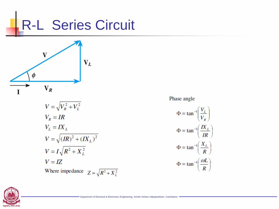
R-L Series Circuit
Department of Electrical & Electronics Engineering, Amrita Vishwa Vidyapeetham, Coimbatore.
R-L Series Circuit

Department of Electrical & Electronics Engineering, Amrita Vishwa Vidyapeetham, Coimbatore.
R-L Series Circuit
Instantaneous power
Average Power

Department of Electrical & Electronics Engineering, Amrita Vishwa Vidyapeetham, Coimbatore.
R-L Series Circuit
Impedance Triangle
Department of Electrical & Electronics Engineering, Amrita Vishwa Vidyapeetham, Coimbatore.
R-L Series Circuit
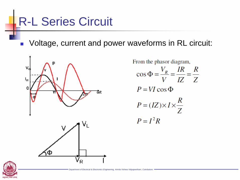
Voltage, current and power waveforms in RL circuit:
Department of Electrical & Electronics Engineering, Amrita Vishwa Vidyapeetham, Coimbatore.
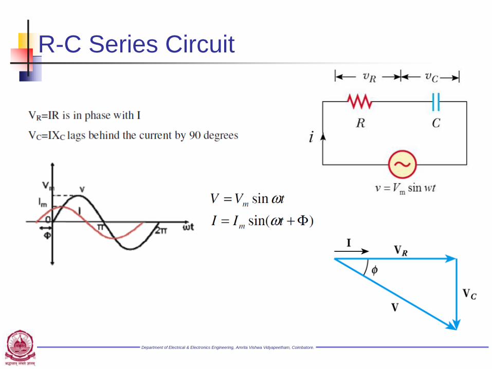
R-C Series Circuit

Department of Electrical & Electronics Engineering, Amrita Vishwa Vidyapeetham, Coimbatore.
R-C Series Circuit

Department of Electrical & Electronics Engineering, Amrita Vishwa Vidyapeetham, Coimbatore.
R-C Series Circuit
Average Power
Impedance triangle

Department of Electrical & Electronics Engineering, Amrita Vishwa Vidyapeetham, Coimbatore.
Series RLC Circuit
By Kirchhoff’s Law
)1
(1
j
]j[
jI
CLjR
CLjRZ
IZ
CX
LjXRI
CX
LjIXIR
V
V
V
Department of Electrical & Electronics Engineering, Amrita Vishwa Vidyapeetham, Coimbatore.
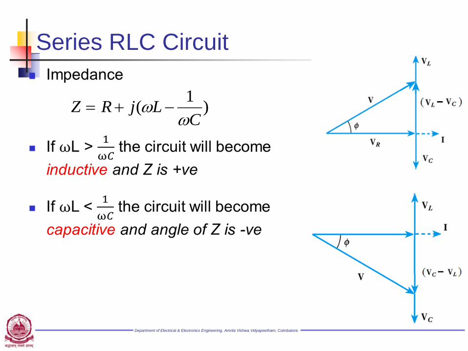
Series RLC Circuit
)1
(C
LjRZ
Department of Electrical & Electronics Engineering, Amrita Vishwa Vidyapeetham, Coimbatore.
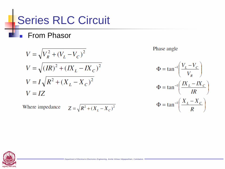
Series RLC Circuit
From Phasor

Department of Electrical & Electronics Engineering, Amrita Vishwa Vidyapeetham, Coimbatore.
Series RLC Circuit
When XL>XC
The phase angle is positive and the circuit is
more inductive than capacitive .
When XL<XC
The phase angle is negative and the circuit is
more capacitive than inductive
When XL=XC
The phase angle = 0 and the circuit is purely
resistive
Department of Electrical & Electronics Engineering, Amrita Vishwa Vidyapeetham, Coimbatore.
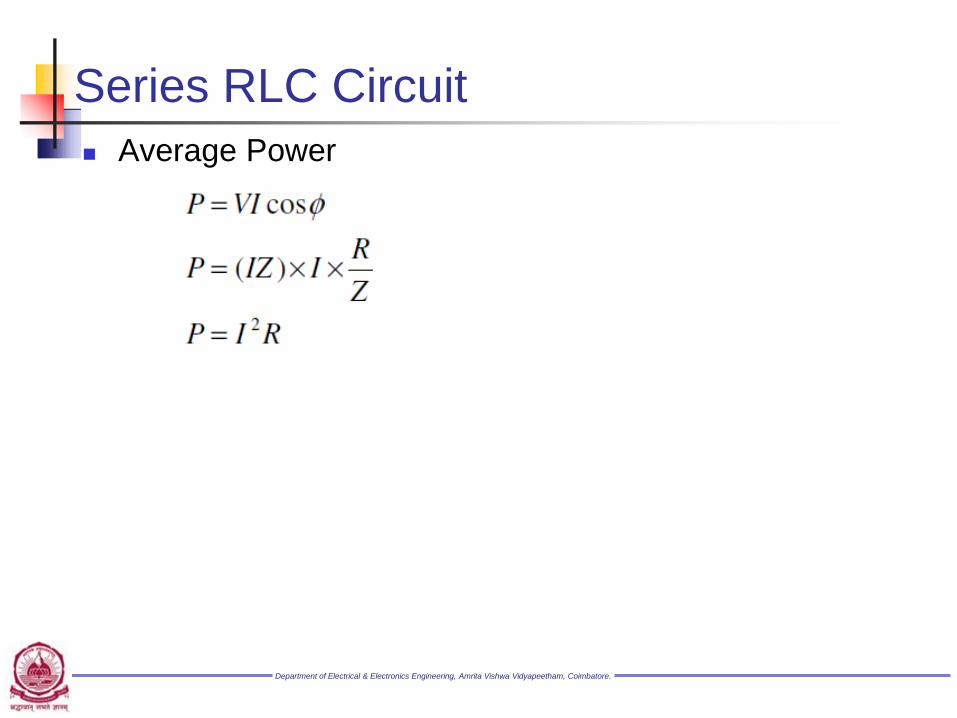
Series RLC Circuit
Average Power

Department of Electrical & Electronics Engineering, Amrita Vishwa Vidyapeetham, Coimbatore.
Summary of Circuit Elements, Impedance, Phase Angles
Department of Electrical & Electronics Engineering, Amrita Vishwa Vidyapeetham, Coimbatore.
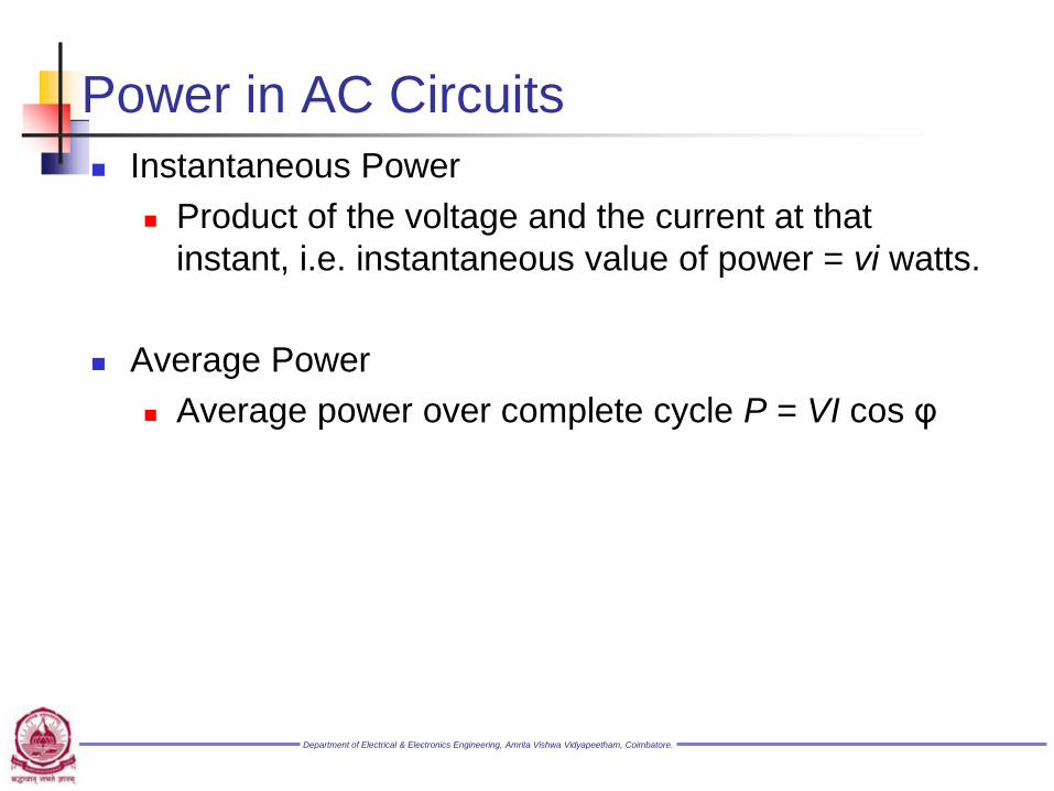
Power in AC Circuits
Instantaneous Power
Product of the voltage and the current at that
instant, i.e. instantaneous value of power = vi watts.
Average Power
Average power over complete cycle P = VI cos φ
Department of Electrical & Electronics Engineering, Amrita Vishwa Vidyapeetham, Coimbatore.
Power in AC Circuits
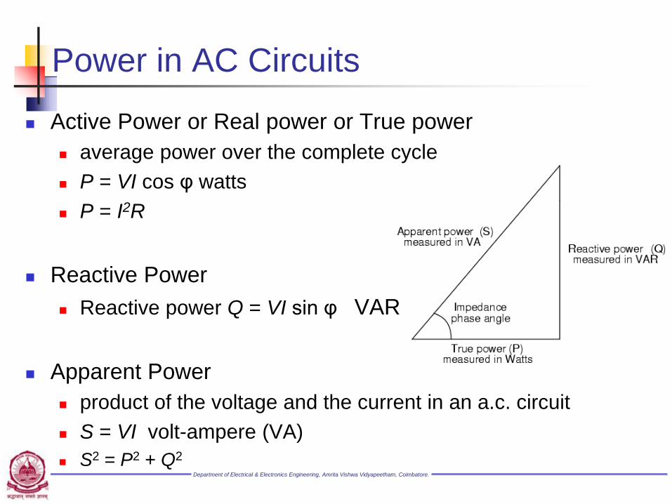
Active Power or Real power or True power
average power over the complete cycle
P = VI cos φ watts
P = I2R
Reactive Power
Reactive power Q = VI sin φ VAR
Apparent Power
product of the voltage and the current in an a.c. circuit
S = VI volt-ampere (VA)
S2 = P2 + Q2

Department of Electrical & Electronics Engineering, Amrita Vishwa Vidyapeetham, Coimbatore.
Power in AC Circuits

Department of Electrical & Electronics Engineering, Amrita Vishwa Vidyapeetham, Coimbatore.
Example #1
A capacitor which has an internal resistance of 10Ω and a
capacitance value of 100uF is connected to a supply
voltage given as V(t) = 100 sin (314t). Calculate the current
flowing into the capacitor. Also construct a voltage triangle
showing the individual voltage drops.
Solution
I = 2.14 A

Department of Electrical & Electronics Engineering, Amrita Vishwa Vidyapeetham, Coimbatore.
Example #2
A coil having a resistance of 7Ω and an inductance of
31.8mH is connected to 230V, 50Hz supply. Calculate
(i) the circuit current (ii) phase angle (iii) power factor
(iv) power consumed

Department of Electrical & Electronics Engineering, Amrita Vishwa Vidyapeetham, Coimbatore.
Example #3
A Capacitor of capacitance 79.5μF is connected in series
with a non inductive resistance of 30Ω across a 100V,
50Hz supply. Find (i) impedance (ii) current (iii) phase
angle (iv) Equation for the instantaneous value of current

Department of Electrical & Electronics Engineering, Amrita Vishwa Vidyapeetham, Coimbatore.
Example #4
A 230 V, 50 Hz ac supply is applied to a coil of 0.06 H
inductance and 2.5Ω resistance connected in series with
a 6.8 μF capacitor. Calculate (i) Impedance (ii) Current
(iii) Phase angle between current and voltage (iv) power
factor (v) power consumed

Department of Electrical & Electronics Engineering, Amrita Vishwa Vidyapeetham, Coimbatore.
Parallel R-L Circuit
Each branch of the circuit can be analysed
separately as a series circuit and then the effect of
the separate branches can be combined by
applying Kirchhoff’s law
I = IR + IL
Department of Electrical & Electronics Engineering, Amrita Vishwa Vidyapeetham, Coimbatore.
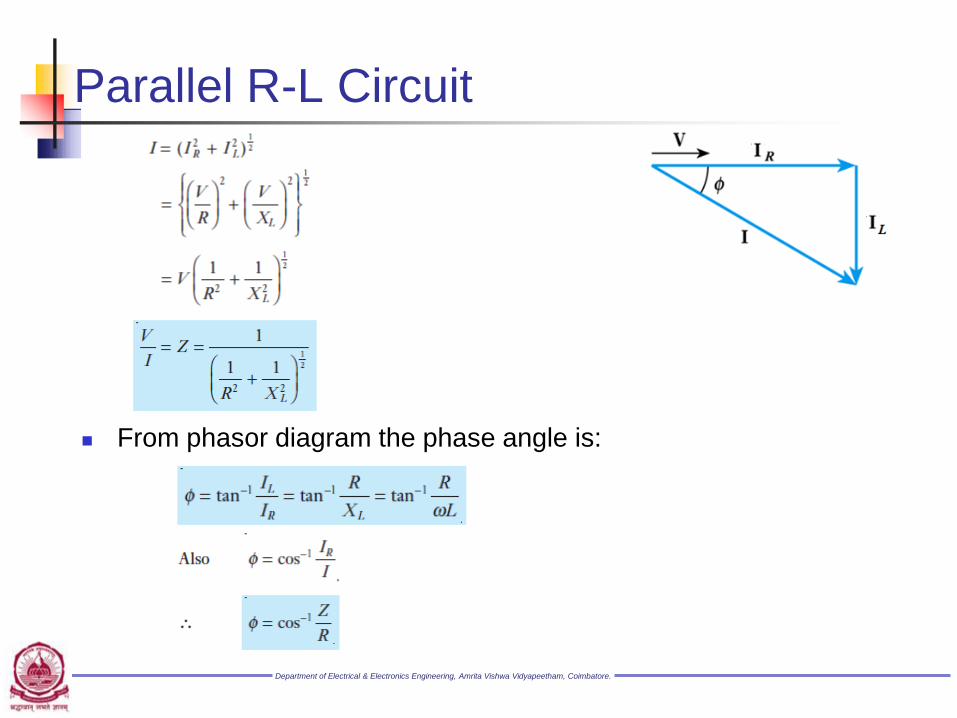
Parallel R-L Circuit
From phasor diagram the phase angle is:

Department of Electrical & Electronics Engineering, Amrita Vishwa Vidyapeetham, Coimbatore.
Parallel R-C Circuit
I = IR + IC

Department of Electrical & Electronics Engineering, Amrita Vishwa Vidyapeetham, Coimbatore.
Parallel R-C Circuit
From phasor diagram the phase angle is:
Department of Electrical & Electronics Engineering, Amrita Vishwa Vidyapeetham, Coimbatore.
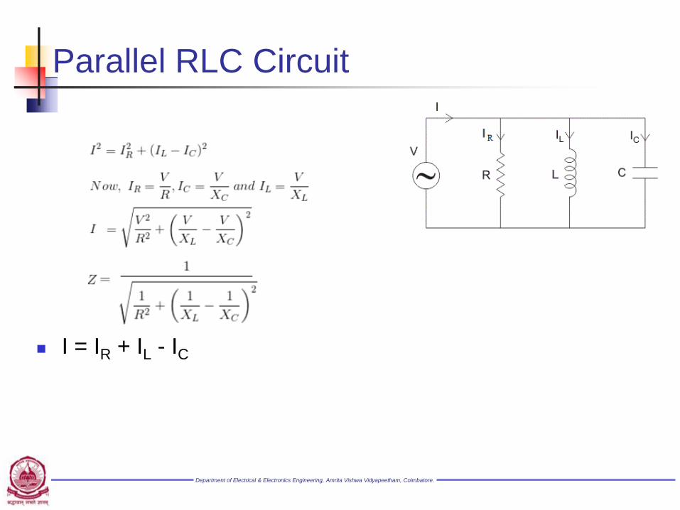
Parallel RLC Circuit
I = IR + IL - IC

Department of Electrical & Electronics Engineering, Amrita Vishwa Vidyapeetham, Coimbatore.
Example #5 A 1kΩ resistor, a 142mH coil and a 160uF capacitor are
all connected in parallel across a 240V, 60Hz supply.
Calculate the impedance of the parallel RLC circuit and
the current drawn from the supply.

Department of Electrical & Electronics Engineering, Amrita Vishwa Vidyapeetham, Coimbatore.
Example #6 A 50Ω resistor, a 20mH coil and a 5uF capacitor are all
connected in parallel across a 50V, 100Hz supply. Calculate
the total current drawn from the supply, the current for each
branch, the total impedance of the circuit and the phase angle.

Department of Electrical & Electronics Engineering, Amrita Vishwa Vidyapeetham, Coimbatore.
Example #6