sinusoidal current control strategy for upqc in grid ... · sinusoidal current control strategy for...
TRANSCRIPT

Sinusoidal Current Control Strategy for UPQC in Grid Connected PV-Fuel Cell
Microgrid Rudranarayan Senapati#1, Rajendr Narayan Senapati*2, Manoj Kumar Moharana#3
# School of Electrical Engineering, KIIT University Bhubaneswar, India-751024 * School of Electrical Sciences, IIT Bhubaneswar Jatni,Khurdha India-752050
1 [email protected] 2 [email protected] 3 [email protected]
Abstract— This paper focuses on the simulation of Unified Power Quality Conditioner (UPQC) with Grid-connected PV-FC (Photovoltaic Fuel Cell) System in grid connected mode. The proposed methodology focuses on drawing the sinusoidal current from the supply system even the presence of non-linear loads in the system draws harmonic current. The harmonic power is provided by the Shunt Controller of UPQC, to restrict the harmonic components to be pulled at the supply, where as the series component is able to balance the voltage related problems such as unbalancing. The UPQC deals with the load harmonic power and the zero sequence power as well resulting to imbalance in the power system, additionally compensating the reactive power, so that the source voltage and the compensated current both will be in phase. The system performance under variable solar irradiance condition has been observed to be invariable.
Keyword- UPQC, Phase Locked Loop, DC-link capacitor, Sinusoidal Current Control Strategy
I. INTRODUCTION
Now a days the necessity of alternative energy sources has given rise to concepts called Smart Grid and Microgrid. These two terms though are forms of power grid, have varied structure and perform with different degree of preparedness with respect to stability, quality and reliability of power being delivered. Stability is the ability of the power system to restore to normalcy after subjected to small or large disturbances. Good quality of power must have low interruption frequency, limited magnitude and period of over and under voltages along with less harmonic distortion, low flicker in the voltage at supply end, as well as less percentage of phase unbalancing and supply frequency fluctuation, etc. Reliability is the ability to supply continuous electricity irrespective of the demands of the consumers, even during disturbance conditions.
In the present scenario the nature of electricity demand is various. Besides being fluctuating in nature the loads now a days are not free from distortions. In particular applications of Power Electronic controllers for various load equipments are mainly liable for poor quality of power. Besides the use of household Inverters and other such electrical equipments are the main culprits in this regard. Besides this there is an increasing competition among renewable energy generation industries to inject more power into the power pool, due to the non-availability of large energy storage equipments. Since the renewable sources generate electricity at low cost, it's quite obvious to use them as the primary sources, though not always. So all these issues are putting onus on the power engineers to develop the compensating equipments that would mitigate the problems.
Power Quality issues related to load voltages are sag, swell, unbalance, flicker, harmonics, etc. Similarly various Power Quality issues related to supply current are harmonics, unbalance loading, etc. The load has always the tendency of drawing the current depending on its type, irrespective of supply voltage to meet the requisite power demanded. Particularly the non-linear type of loads have tendency of drawing harmonic current and certain loads also draw unbalanced current, leading to disturbances in supply current. Since the current has to be generated by the supply system generator, it has to produce harmonic voltage to meet the power needed [1]. In case of non-stiff sources (sources with high input impedance) harmonic voltage gets introduced into the system. This problem is less severe in systems with stiff sources. But our practical system consists of mostly non-stiff sources. Besides this another reason for introduction of harmonics is imperfections of PWM control circuitry. In particular DG integrated systems with lower fault levels, there is increased vulnerability of system to harmonic penetration.
Such PQ problems may be mitigated by using a custom power devices. Custom power is relevant to the use of power electronic controllers for distribution systems. Under this scheme an end consumer receives a pre-specified quality power. It not only meets the rising demand, but improves the quality and fidelity of power supply. Out of several Custom Power devices Unified Power Quality Conditioner (UPQC) is quite popular. UPQC is a combination of SAF and ShAF, commonly known as UPQC. As the name suggests, it is concerned
ISSN (Print) : 2319-8613 ISSN (Online) : 0975-4024 Rudranarayan Senapati et al. / International Journal of Engineering and Technology (IJET)
DOI: 10.21817/ijet/2017/v9i4/170904005 Vol 9 No 4 Aug-Sep 2017 2800

with the common objective of synchronically mitigating all the PQ issues related to voltage, current amplitude and frequency. Simultaneously it also achieves the Power Factor enhancement and Phase Unbalancing as well. As numerous research papers have already been published on UPQC so far. Therefore, the intention behind this section is to put some information highlighting the future possibilities and prospects as open for researchers working in the field of PQ.
II. CUSTOM POWER DEVICE
UPQC, as proposed by H. Akagi is a custom power device that has similar functions as Unified Power Flow Controller in the distribution network. It compensates voltage and current related PQ issues and improves the power factor also. It consists of a pair of back to back connected inverters through common dc link equipment. UPQC topology may be characterised as Voltage Source Inverter (VSI) based UPQC and Current Source Inverter (CSI) based UPQC as depend on the DC link equipment.
VSI topology (Fig.1) has capacitor as the DC link equipment and CSI topology has inductor as the DC link equipment. Due to the advantage of compact size and cost effectiveness of VSI based UPQC topology is widely implemented among the two topologies. In contrast to VSI topology CSI topology has bulky DC-side filter. But the advantage of CSI based topology is its excellent controllability, easy protection, high reliability. In VSI topology, the shunt inverter provides the required harmonic currents desired by the load. Simultaneously it improves the power factor and voltage profile by supplying the reactive power. Besides this VSI based UPQC possesses shunt coupling inductor marked by Lsh in the diagram, which connects the shunt inverter to the load circuit. A coupling transformer of suitable turns ratio is used in the series inverter circuit for minimizing the kVA rating of series inverter.
Fig. 1. Schematic representation of UPQC
The faster sensing of disturbances with high certainty and faster signal processing is the main facet of UPQC control based on which performance of the power conditioner confide. The control strategy of UPQC deals with the actuation of the reference signals regulating the switching pattern of inverter switches to consummate the appropriate performance. Various controlling methods, algorithms and techniques have been proposed by different researchers which are quite easily adopted by the UPQC system. Several researchers have proposed control strategy for a specific configuration of UPQC. Lee et al. [1] proposed a control strategy for UPQC-Q which offers minimum active power injection by which voltage sag can be compensated effectively and economically. Khadkikar et al.[2] suggested the control method of series inverter of UPQC by using power angle control(PAC) series inverter can compensate both voltage sag/swell and load reactive power sharing between two inverters. As the model controls both active and reactive power flow the model named as UPQC-S. Khadem et al. [3] proposes a new topology of UPQC i.e. UPQC in DG-connected microgrid. In this paper both active power and reactive power can be controlled by DG and UPQC. DG provides required active power and shunt part of UPQC provides required reactive power for compensation of both reactive and harmonics power in islanding mode and interconnected mode. dos Santos et al. [4] presented control technique for Dual-UPQC. Traditional UPQC is controlled using non-sinusoidal reference whereas Dual-UPQC is controlled as sinusoidal references i.e. for series filter controlled as sinusoidal current source and shunt filter controlled as sinusoidal
ISSN (Print) : 2319-8613 ISSN (Online) : 0975-4024 Rudranarayan Senapati et al. / International Journal of Engineering and Technology (IJET)
DOI: 10.21817/ijet/2017/v9i4/170904005 Vol 9 No 4 Aug-Sep 2017 2801

voltage source. Dual-UPQC is applicable for low-voltage application and independent of leakage impedance and harmonics content. Teke et al. [5] described about construction and operation of Open-UPQC and a comparison study of performance with traditional UPQC in this paper. There is no dc-link part in case of UPQC. Both inverters are based upon enhanced phase locked loop (E-PLL) and non-linear adaptive filter. Guo et al. [6] presents the control and design methods for current source-UPQC. Because of the use of uni-polar modulation and parameter design, the filter size reduces and it improves the control dynamics. With the application of modified repetitive control schemes, harmonics compensation was done effectively. A fault current limiting scheme by using large dc-link inductor is also presented in this paper. Senthilnathan et al. [27] proposed UPQC-L Topology with photo voltaic (PV) source and ultra-capacitor with a buck–boost converter which is utilized for maintaining the constant DC-link current. The compensation of sag, swell, unbalance, fault conditions is done by proposed UPQC-CSC model. The control algorithm for UPQC is based on synchronous reference frame theory and hysteresis loop for the pulse generation. Pattnaik et al. [28] suggested power angle control concept between series and shunt APF parts of UPQC-L with equal reactive power sharing with the controller to equalize VA ratings of the two APFs. Rauf et al. proposed a ten-switch topology of UPQC [31]. Xu et al. proposed a Matrix converter based topology of UPQC [32]. Classification of different UPQC topologies has been presented by V. Khadkikar [7].
Several other control strategies have been described in different literatures [9-26, 29-30]. Axente et al.[8] proposed a sequence based compensation strategy to compensate both balanced and unbalanced sags. With grid frequency variation, for the effective operation of UPQC a PLL-less software synchronization method has been introduced. Axente et al.[9] has suggested that the protection of series part of UPQC from over current and over voltage because of the short circuit faults occurs over voltage and over current. Karanki et al.[10] provided information about a new feedback controller i.e particle swarm optimization based feedback controller for UPQC by which unbalanced voltage and distorted load currents can be compensated more effectively as compared to conventional feedback controller. Kinhal et al.[11] has suggested application of artificial intelligence i.e artificial neural network based controller for shunt active filter. A digital signal processor based microcontroller is used for the implementation of the control algorithm. Heydari et al.[12] described about the design of combination of UPQC and superconducting fault current limiter(SFCL) which is based on normalized simulated annealing algorithm. Use of SFCL reduces the cost of installation of UPQC by reducing volt-ampere rating of UPQC as it limits the fault current. Khadkikar et al.[13] presented a DSP-based experimental observation of single phase UPQC. Leon et al.[14] proposed a new control strategy for UPQC in which shunt converter acts as voltage source and series converter acts as a current source instead of traditional UPQC. In this paper an optimal voltage angle at load terminals is implemented for minimization of converter losses. Teke et al. [15] presented a novel reference signal generation scheme for UPQC. An enhanced PLL and nonlinear adaptive filter is used for shunt and series converter controller and fuzzy logic controller is used for dc-link control. Muñoz et al. [16] presented a discrete time linear control strategy i.e. a classical design method which is based on root locus to get the dynamical behavior of the system. Using this method reactive power and fundamental frequency disturbances can be compensated effectively. Sivakumar et al. [17] described the compensation method for voltage sags problems. In this paper objective function is to minimize the real power injection and constraints are injected voltage limit on the series active filter, phase jump mitigation and angle of voltage injection. A solution to the objective function is found by particle swarm optimization method. Kwan et al. [18] presented control design for UPQC using Output Regulation (OR) theory in which Kalman filter is used for extracting the state components of the unbalanced supply voltage and distorted load current. Along with this a linear quadratic regulation based self-charging circuit is implemented with-out depending on external dc source. Melín et al. [19] proposed a current source converter based UPQC in which objective function is to minimize dc current level so that it compensate the load power factor and voltage disturbances at point of common coupling (PCC) like voltage source converter based UPQC. Karanki et al. [20] proposed a new topology for UPQC in which without changing the compensation capability dc-link voltage reduced for non-stiff source. Instead of using a bulky capacitor for dc-link three capacitors in series with interfacing inductors are placed in this topology to match the dc-link voltage requirement of shunt active filter for a 3-phase 4-wire system. Li et al. [21] presented a cross-phase connected UPQC which is capable of compensating both load terminal voltage and load current simultaneously and effectively by making it sinusoidal and balanced. Particularly this topology is used for single phase voltage sags which is compensated completely. Khadkikar et al. [22] presented the operation and control mechanism of UPQC with the application of power angle control(PAC) under voltage sag and swell conditions. Fixed power angle and variable power angle methods are used in this paper. For voltage swell fixed power angle method and for voltage sag variable power angle method is suitable.
Ambati et al. [23] proposes an optimum method to design UPQC- . The rating of series and shunt inverter should be minimized to get same output at a lower size of inverter. In this method VA loading can be optimized for reduced power loss. Ganguly et al. [24] proposes a pso-based algorithm for reactive power compensation in case of radial distribution using UPQC-PAC. In this paper, both series and shunt inverter are
ISSN (Print) : 2319-8613 ISSN (Online) : 0975-4024 Rudranarayan Senapati et al. / International Journal of Engineering and Technology (IJET)
DOI: 10.21817/ijet/2017/v9i4/170904005 Vol 9 No 4 Aug-Sep 2017 2802

responsible for reactive power compensation by minimizing objective function i.e. rating of UPQC, network power loss, percentage of nodes with under voltage problem, UPQC parameters can be designed. Patjoshi et al. [25] proposed a model reference control strategy with known coefficients for the generation of reference signals for the control circuit of both shunt and series inverter. In the control he used direct adaptive control to track the error between model reference output and measured signal to be controlled. Monteiro et al. [26] proposed a dual independent control strategy for a UPQC without series transformer based on the active and non-active currents, where the two control occur independently by two DSP controllers without any communication between them. Lu et al. [29] proposed Space Vector Modulation strategy for Single-Phase Transformerless Three-Leg UPQC. Modesto et al. [30] employed a dual compensation strategy such that the controlled quantities are always sinusoidal, thereby; the series converter is controlled to act as a sinusoidal current source, whereas the parallel converter operates as a sinusoidal voltage source. Kesler et al.[33] described about compensation of power quality problems at the point of common coupling on power distribution network by using three phase four wire UPQC with synchronous reference frame based control strategy.
Apart from that also many advanced control techniques have also been utilized. Sliding Mode Control is a robust control strategy, widely accepted by researchers. It is based on the concept of variable structure system. An UPQC has similar construction as that of unified power flow controller (UPFC) as an adaptable flexible AC transmission systems (FACTS) devices for the transmission system in practice. Then there is an obvious question, why UPQC. The answer may be as the device provides compensation to voltage and current related problems coherently with series and shunt inverter. An UPFC performs in balanced and somewhat distortion free transmission system whereas UPQC is meant to operate in relatively unbalanced distribution systems with higher intensity of harmonics due to the rising trend of PE interfaces.
III. UPQC-DG
UPQC integrated to distributed generation network is termed as UPQC-DG. It faces lots of challenges towards the control of active power transfer, compensation of non active power during Islanded mode, etc. Apart from theses also numerous operational changes are also incorporated, e.g., islanding detection and isolation, delay in reconnection as well as interchanges in between the voltage and current control mode, etc., which further increases the complexity in the systems. In the UPQC-DG, with storage, such as battery and flywheel storage, the shunt part of UPQC is in connection with the PCC, whereas the series part is positioned prior to the PCC in series with the grid. In case the storage is present, the DC link may be hooked up with it [2]. The benefits obtained by introducing a secondary control as a smart islanding detection and reconnection technique (IR) in the UPQC may be summarized as:
i) Compensation of voltage related issues in the interconnected mode to avoid Islanding.
ii) Compensation of non-active Reactive and Harmonic Power (QH) of the load during islanded mode.
iii) Smooth operation of the system at the time of phase jump/difference (within limit).
A. Interconnected Mode
Here:
i. The fundamental active power is delivered by DG to the grid, battery and load.
ii. The ShAF preferably the Parallel Active Filter (PAF) mitigates the VAR (Volt-Ampere Reactive) and distorted power of the non-linear load to limit the Total Harmonic Distortion at the PCC.
iii. Any sorts of Voltage disturbances may be redressed by the True power from the grid/battery through the SAF. At the PCC due to absence of disturbance, DG converter remains connected in all conditions.
iv. During supply suspension/black out, signal has be send to the DG converter to be islanded through UPQC.
B. Islanded Mode
Here:
i. The SAF is detached at the time of failure of grid, but DG converter has to remain connected for proper maintenance of PCC terminal voltage.
ii. The ShAF continues to compensate the harmonic power of the non-linear loads to furnish the harmonic free current at PCC for all the other linear loads.
iii. As the DG system with enough cache supplies the active power, need not be isolated from the system.
iv. The SAF is again reconnected with the availability of grid power.
IV. PROPOSED METHODOLOGY
The proposed methodology used is based on improvement of PQ by UPQC for a Grid integrated PV-system whose output has been fed to a Boost Converter and in turn the output of boost converters is connected to grid through SVPWM inverter. The schematic of the inverter control circuitry is shown in Fig. 2.
ISSN (Print) : 2319-8613 ISSN (Online) : 0975-4024 Rudranarayan Senapati et al. / International Journal of Engineering and Technology (IJET)
DOI: 10.21817/ijet/2017/v9i4/170904005 Vol 9 No 4 Aug-Sep 2017 2803

Fig. 2. Inverter Control Circuitry
For the development of the PV system the Perturb and Observe method of MPPT algorithm has been used which is given in Fig. 3.
Fig. 3. Perturb and Observe Algorithm
The PV unit output has been fed through a Boost converter with a switching frequency of 5 kHz. The output of the boost converter is fed to the grid after its conversion to AC by a Voltage Source Converter (VSC). The non-linear load circuit consists of a 3-phase converter fed load. Certain single phase loads were introduced into the system deliberately making the system unbalanced for further performance analysis of UPQC. In this paper analysis of UPQC control in dq-reference has been presented.
An appropriate representation of instantaneous active power 0p (zero sequence power) is suggested in αβ0-reference frame as the instant power along with p (instantaneous true power) and q (instantaneous VAR power) additionally [5] which can be expressed mathematically as:
p v 0 0 i0 0 0p = 0 v v iα αβq iβ0 v -vαβ
(1)
The 3-φ instantaneous active power is: P =v i +v i +v i =v i +v i +v i =p+pa a c c α α3- 0 0 0b b β β (2)
ISSN (Print) : 2319-8613 ISSN (Online) : 0975-4024 Rudranarayan Senapati et al. / International Journal of Engineering and Technology (IJET)
DOI: 10.21817/ijet/2017/v9i4/170904005 Vol 9 No 4 Aug-Sep 2017 2804

Whereas
0
O scillating C om ponentA verage V alueof Zero S equence P ow erof the Zero S equence
Pow er aids the
total energy transfe
0
r
p = p +0 p
(3)
And
1q=v i - v i = v i + v i + v iα α c a caβ β ab bc b3 (4)
Fig. 4. Physical implication of instantaneous power in αβ0 -frame.
0p+p Instantaneous power flow (Total) per unit-time. q Transfer of power among the three phases without any transfer of energy
[Where a b ci ,i ,iand a b cv ,v ,v
are the Instantaneous Current and Voltage in abc frame. α β 0i ,i ,i and
α β 0v ,v ,vare the Instantaneous Current and Voltage in αβ0 -frame].
Where, α and β components of current can be obtained taking the oscillating active and reactive powers as: v v v vi α αβ βp 0α 1 1
= +i 2 2 2 2v -v 0 v -v qv +v v +vβ α αα αβ ββ β
ActivePart ReactivePart
(5)
The abc true and imaginary current to be obtained by using Inverse Clarke's Transformation as follows:
i 1 0a (p ) v i + v i vα α α2 β β31i = - 2 2 vb p 2 23 v + v βα β31i - -c p 2 2
(6)
i va q b cv i + v i + v ic a c aa b b c bi = v c ab q 2 2 2v + v + v c a va b b c a bic q
(7)
A. Shunt Inverter control
To compensate for the harmonic power and the required reactive VAR, the design of the control strategy of Shunt inverter is required. This control strategy is based on p-q theory put forward by H. Akagi. He has described three different control strategies for ShAF. These are:
Constant instantaneous power control strategy: In this technique, the ShAF compensates the oscillating real-power, which is non reactive power other than fundamental active power.
Sinusoidal current control strategy: It ensures sinusoidal current to be taken from the source.
Generalized Fryze current control strategy: This strategy is based on linearization of relationship between voltage and current even under distorted current condition [14].
ISSN (Print) : 2319-8613 ISSN (Online) : 0975-4024 Rudranarayan Senapati et al. / International Journal of Engineering and Technology (IJET)
DOI: 10.21817/ijet/2017/v9i4/170904005 Vol 9 No 4 Aug-Sep 2017 2805

Fig. 5. Block diagram of Shunt Inverter control
Among all the control strategies Sinusoidal current control strategy has drawn the attention of the researchers the most due to its ease of implementation. In this work, Sinusoidal current control strategy has been used for the design of the ShAF control. It is incorporated along with the ShAF accounts for the distorted power to ensure the power frequency current to be drawn at the supply terminal.
To have the compensated current and the fundamental positive sequence voltage to be in phase, the ShAF supplies the Reactive Power of appropriate magnitude and polarity. But, it fails to generate the Real Power (constant) as long as the voltage of the system is non-sinusoidal and unbalanced.
B. Series Inverter control
Voltage related problems like voltage sag or swell, harmonics, due to various reasons like transients, nonlinearity and interruptions can be minimized using SAF. The difference between the positive sequence
voltage abcV and the distorted source voltage R_abcV, acts as the reference input to the control circuit of the series
inverter of UPQC. Compensation of voltage disturbances requires power balancing between the supply end and load end. In order to attain that the DC- link voltage is managed to be constant. A PI controller can be incorporated to retain the DC- link capacitor voltage. The detailed control strategy has been described in Fig. 6.
Fig. 6. Block diagram for series inverter control
V. RESULTS AND DISCUSION
In this work operation of UPQC in grid integrated PV-Fuel Cell network has been simulated for a 3P3W system using MATLAB\SIMULINK 2016a. The control circuitry for 3P3W is modeled for both grid connected PV-Fuel Cell system in stand-alone and grid connected mode. The circuit parameters used for simulation has been given in Table I for grid connected mode under constant and variable irradiance conditions. Here three different case have been simulated. The first case consists of constant irradiance condition in which the irradiance is kept at 550W/m2. The second case consists of variable irradiance condition in which the variation in irradiance is simulated using signal builder. The third case comprises the case of load variation in which the irradiance is kept fixed where as the load is varied. In the fourth case both the irradiance as well as the load is varied simultaneously. The simulation parameters have been given in Table I.
ISSN (Print) : 2319-8613 ISSN (Online) : 0975-4024 Rudranarayan Senapati et al. / International Journal of Engineering and Technology (IJET)
DOI: 10.21817/ijet/2017/v9i4/170904005 Vol 9 No 4 Aug-Sep 2017 2806

Table I Simulation Parameters
Load Parameter Value
Nonlinear Load Resistance 2000W
Inductance 100VA
DC Link Capacitance 1000µF
Grid Voltage 230V
All the conditions have been discussed in grid connected condition. The system block diagram has been shown in Fig. 7.
Fig.7. System Block Diagram
ISSN (Print) : 2319-8613 ISSN (Online) : 0975-4024 Rudranarayan Senapati et al. / International Journal of Engineering and Technology (IJET)
DOI: 10.21817/ijet/2017/v9i4/170904005 Vol 9 No 4 Aug-Sep 2017 2807

Under constant irradiance of 550W/m2 the Grid injected voltage fro PV-FC side is given in Fig. 8.
Fig. 8 Grid Injected Voltage and Current
The injected voltage and Current of the UPQC shunt inverter in the Load Circuit is given in Fig. 9.
Fig. 9 UPQC Injected Voltage and Current
The Load voltage and Current waveform of the 3-phase nonlinear load is given in Fig. 10.
Fig. 10. Load Voltage and Current
ISSN (Print) : 2319-8613 ISSN (Online) : 0975-4024 Rudranarayan Senapati et al. / International Journal of Engineering and Technology (IJET)
DOI: 10.21817/ijet/2017/v9i4/170904005 Vol 9 No 4 Aug-Sep 2017 2808

The Load Voltage THD is found to be 18.36 percent. Information about different Harmonics present can be seen from Fig.11.
Fig. 11. THD in Load Voltage
The Total Demand Distortion in source current is found to be 3.14 percent. Information regarding different harmonics can be presented in Fig. 12.
Fig. 12. TDD in Source Current
Now it is found that the Source current fundamental has an RMS value of 234.1. The Source current has a THD of 3.15 which is quite low as desired. The load input voltage has a THD of 18.36 percent as the load is linear. It is found that the source current is near to fundamental which is desired as in Sinusoidal current control strategy.
Now let's consider the consider the case of variable irradiance with constant load. Under this condition the Grid injected current and corresponding voltage can be obtained as in Fig. 13.
Fig.13. Grid Injected Voltage as in Const. Load Variable Irradiance Condition
ISSN (Print) : 2319-8613 ISSN (Online) : 0975-4024 Rudranarayan Senapati et al. / International Journal of Engineering and Technology (IJET)
DOI: 10.21817/ijet/2017/v9i4/170904005 Vol 9 No 4 Aug-Sep 2017 2809
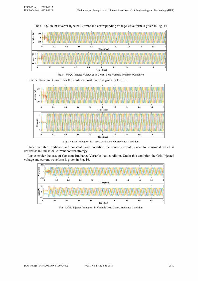
The UPQC shunt inverter injected Current and corresponding voltage wave form is given in Fig. 14.
Fig.14. UPQC Injected Voltage as in Const. Load Variable Irradiance Condition
Load Voltage and Current for the nonlinear load circuit is given in Fig. 15.
Fig. 15. Load Voltage as in Const. Load Variable Irradiance Condition
Under variable irradiance and constant Load condition the source current is near to sinusoidal which is desired as in Sinusoidal current control strategy.
Lets consider the case of Constant Irradiance Variable load condition. Under this condition the Grid Injected voltage and current waveform is given in Fig. 16.
Fig.16. Grid Injected Voltage as in Variable Load Const. Irradiance Condition
ISSN (Print) : 2319-8613 ISSN (Online) : 0975-4024 Rudranarayan Senapati et al. / International Journal of Engineering and Technology (IJET)
DOI: 10.21817/ijet/2017/v9i4/170904005 Vol 9 No 4 Aug-Sep 2017 2810

The UPQC shunt inverter injected Current and corresponding voltage wave form is given in Fig. 17.
Fig.17. UPQC Injected Voltage as in Variable Load Const. Irradiance Condition
Load Voltage and Current for the nonlinear load circuit is given in Fig. 18.
Fig. 18. Load Voltage as in Variable Load Const. Irradiance Condition
Under Constant irradiance and variable Load condition the source current is near to sinusoidal which also satisfies Sinusoidal current control strategy.
Now Let's consider the case of Variable Irradiance Variable load condition. Under this condition the Grid Injected voltage and current waveform is given in Fig. 19.
Fig.19. Grid Injected Voltage as in Variable Load Variable Irradiance Condition
ISSN (Print) : 2319-8613 ISSN (Online) : 0975-4024 Rudranarayan Senapati et al. / International Journal of Engineering and Technology (IJET)
DOI: 10.21817/ijet/2017/v9i4/170904005 Vol 9 No 4 Aug-Sep 2017 2811

The UPQC shunt inverter injected Current and corresponding voltage wave form is given in Fig. 20.
Fig.20. UPQC Injected Voltage as in Variable Load Variable Irradiance Condition
Voltage and Current for the nonlinear load circuit is given in Fig. 21.
Fig.21. Load Voltage as in Variable Load Variable Irradiance Condition
Under variable irradiance and variable Load condition the source current is near to sinusoidal which also satisfies Sinusoidal current control strategy.
VI. CONCLUSION
From the above four cases it is observed that The UPQC control strategy performs well in all the conditions to mitigate the power quality disturbance owing to variation in Irradiance or variation in load. It is seen in case of load variations the load is varied at an interval of 0.5 sec, but it is found that the variation in load has no impact on the load voltage or the voltage in the connected circuit. A sudden rise in load, leads to sag, which is seen to have been mitigated by the action of UPQC. Similarly the change in load has no impact on grid injected voltage and current and voltage waveform. So it is clear that the performance of UPQC is satisfactory in all the three conditions.
REFERENCES [1] W. C. Lee, D. M. Lee, T. K. Lee, " New control scheme for a unified power-quality compensator-Q with minimum active power
injection," IEEE Transactions on Power Delivery, pp. 1068-76, vol. 25, no. 2, Apr. 2010. [2] V. Khadkikar, A. Chandra "UPQC-S: A novel concept of simultaneous voltage sag/swell and load reactive power compensations
utilizing series inverter of UPQC," IEEE transactions on power electronics, vol. 26, no. 9, pp. 2414-25, Sep. 2011. [3] S. K. Khadem, M. Basu, M. F. Conlon, "A new placement and integration method of UPQC to improve the power quality in DG
network," Power Engineering Conference (UPEC), pp. 1-6, Sep 2013. [4] R. J. dos Santos, J.C. da Cunha, M. Mezaroba, "A simplified control technique for a dual unified power quality conditioner" IEEE
Transactions on Industrial Electronics, pp. 5851-60, vol. 61, no. 11, Nov 2014. [5] Tekoae A, Meral ME, Cuma MU, Tümay M, Bayindir KÇ. OPEN unified power quality conditioner with control based on enhanced
phase locked loop. IET Generation, Transmission & Distribution. 2013 Mar 1;7(3):254-64. [6] Guo W, Xiao L, Dai S. Control and design of a current source united power quality conditioner with fault current limiting ability. IET
Power Electronics. 2013 Feb;6(2):297-308. [7] Khadkikar, V. (2012). Enhancing electric power quality using UPQC: A comprehensive overview. IEEE transactions on Power
Electronics, 27(5), 2284-2297. [8] Axente I, Ganesh JN, Basu M, Conlon MF, Gaughan K. A 12-kVA DSP-controlled laboratory prototype UPQC capable of mitigating
unbalance in source voltage and load current. IEEE Transactions on power Electronics. 2010 Jun;25(6):1471-9. [9] Axente I, Basu M, Conlon MF, Gaughan K. Protection of unified power quality conditioner against the load side short circuits. IET
power electronics. 2010 Jul 8;3(4):542-51. [10] Karanki SB, Mishra MK, Kumar BK. Particle swarm optimization-based feedback controller for unified power-quality conditioner.
IEEE transactions on power delivery. 2010 Oct;25(4):2814-24. [11] Kinhal VG, Agarwal P, Gupta HO. Performance investigation of neural-network-based unified power-quality conditioner. IEEE
Transactions on Power Delivery. 2011 Jan;26(1):431-7.
ISSN (Print) : 2319-8613 ISSN (Online) : 0975-4024 Rudranarayan Senapati et al. / International Journal of Engineering and Technology (IJET)
DOI: 10.21817/ijet/2017/v9i4/170904005 Vol 9 No 4 Aug-Sep 2017 2812

[12] Heydari H, Moghadasi AH. Optimization scheme in combinatorial UPQC and SFCL using normalized simulated annealing. IEEE Transactions on Power Delivery. 2011 Jul;26(3):1489-98.
[13] Khadkikar V, Chandra A, Barry AO, Nguyen TD. Power quality enhancement utilising single-phase unified power quality conditioner: digital signal processor-based experimental validation. IET Power Electronics. 2011 Mar 1;4(3):323-31.
[14] Leon, Andres E., S. J. Amodeo, Jorge A. Solsona, and M. I. Valla. "Non-linear optimal controller for unified power quality conditioners." IET Power Electronics 4, no. 4 (2011): 435-446.
[15] Teke, A., Saribulut, L., & Tumay, M. (2011). A novel reference signal generation method for power-quality improvement of unified power-quality conditioner. IEEE Transactions on power delivery, 26(4), 2205-2214.
[16] Munoz, J. A., Espinoza, J. R., Baier, C. R., Moran, L. A., Espinosa, E. E., Melin, P. E., & Sbarbaro, D. G. (2012). Design of a discrete-time linear control strategy for a multicell UPQC. IEEE Transactions on industrial electronics, 59(10), 3797-3807.
[17] Kumar, G. S., Kumar, B. K., & Mishra, M. K. (2011). Mitigation of voltage sags with phase jumps by UPQC with PSO-based ANFIS. IEEE Transactions on Power Delivery, 26(4), 2761-2773.
[18] Kwan, K. H., So, P. L., & Chu, Y. C. (2012). An output regulation-based unified power quality conditioner with Kalman filters. IEEE Transactions on Industrial Electronics, 59(11), 4248-4262.
[19] Melín, P. E., Espinoza, J. R., Morán, L. A., Rodriguez, J. R., Cardenas, V. M., Baier, C. R., & Muñoz, J. A. (2012). Analysis, design and control of a unified power-quality conditioner based on a current-source topology. IEEE transactions on power delivery, 27(4), 1727-1736.
[20] Karanki, S. B., Geddada, N., Mishra, M. K., & Kumar, B. K. (2013). A modified three-phase four-wire UPQC topology with reduced DC-link voltage rating. IEEE transactions on industrial electronics, 60(9), 3555-3566.
[21] Li, G. J., Ma, F., Choi, S. S., & Zhang, X. P. (2012). Control strategy of a cross-phase-connected unified power quality conditioner. IET Power Electronics, 5(5), 600-608.
[22] Khadkikar, V. (2013). Fixed and variable power angle control methods for unified power quality conditioner: operation, control and impact assessment on shunt and series inverter kVA loadings. IET Power Electronics, 6(7), 1299-1307.
[23] Ambati, B. B., & Khadkikar, V. (2014). Optimal sizing of UPQC considering VA loading and maximum utilization of power-electronic converters. IEEE transactions on power delivery, 29(3), 1490-1498.
[24] Ganguly, S. (2014). Multi-objective planning for reactive power compensation of radial distribution networks with unified power quality conditioner allocation using particle swarm optimization. IEEE Transactions on Power Systems, 29(4), 1801-1810.
[25] Patjoshi, R. K., & Mahapatra, K. (2016). High-performance unified power quality conditioner using command generator tracker-based direct adaptive control strategy. IET Power Electronics, 9(6), 1267-1278.
[26] Monteiro, L. F. C., Aredes, M., Pinto, J. G., Exposto, B. F., & Afonso, J. L. (2016). Control algorithms based on the active and non-active currents for a UPQC without series transformers. IET Power Electronics, 9(9), 1985-1994.
[27] Senthilnathan, K., & Annapoorani, I. (2016). Implementation of unified power quality conditioner (UPQC) based on current source converters for distribution grid and performance monitoring through LabVIEW Simulation Interface Toolkit server: a cyber physical model. IET Generation, Transmission & Distribution, 10(11), 2622-2630.
[28] N. Patnaik, A. K. Panda, P. R. Mohanty, "Performance and comparative rating evaluation of single phase left shunt UPQC," International Conference on Power Electronics, Drives and Energy Systems, pp. 1-6, 2016.
[29] Lu, Y., Xiao, G., Wang, X., Blaabjerg, F., & Lu, D. (2016). Control strategy for single-phase transformerless three-leg unified power quality conditioner based on space vector modulation. IEEE Transactions on Power Electronics, 31(4), 2840-2849.
[30] Modesto, R. A., da Silva, S. A. O., de Oliveira, A. A., & Bacon, V. D. (2016). A Versatile Unified Power Quality Conditioner Applied to Three-Phase Four-Wire Distribution Systems Using a Dual Control Strategy. IEEE Transactions on Power Electronics, 31(8), 5503-5514.
[31] Rauf, A. M., Sant, A. V., Khadkikar, V., & Zeineldin, H. H. (2016). A Novel Ten-Switch Topology for Unified Power Quality Conditioner. IEEE Transactions on Power Electronics, 31(10), 6937-6946.
[32] Xu, Q., Ma, F., Luo, A., He, Z., & Xiao, H. (2016). Analysis and Control of M3C-Based UPQC for Power Quality Improvement in Medium/High-Voltage Power Grid. IEEE Transactions on Power Electronics, 31(12), 8182-8194.
[33] Kesler, M., & Ozdemir, E. (2011). Synchronous-reference-frame-based control method for UPQC under unbalanced and distorted load conditions. IEEE Transactions on Industrial Electronics, 58(9), 3967-3975.
AUTHOR PROFILE
Rudranarayan Senapati received the B.E. degrees in Electrical Engineering from Indira Gandhi Institute of Technology (IGIT), Sarang, Odisha, India, in 2001 and M. Tech degree in Communication Systems Engineering, from KIIT University in 2006. Currently he is working as Assistant Professor in School of Electrical Engineering, KIIT University since 2005. His current research interests include grid integration of renewable energy sources, power quality conditioners and power quality control and analysis, smart grids and Micro Grids.
Rajendra Narayan Senapati did his B Tech in Electrical Engineering from IGIT Sarang in 2011 and M Tech from IIT Roorkee in 2014. He is currently working in the field of Smart Grid and Power Quality issues in smart grid.
Manoj Kumar Maharana did his AMIE in Electrical Engineering in 1997. Then he completed his M Tech in Power System from NIT Warangal in 2001.He pursued PhD degree from IIT Madras in 2010. Currently he is working as Associate Dean and Associate Professor in School of Electrical Engineering, KIIT University. His area of interest includes Power system operation control, Smart Grid, Energy management in Micro grid.
ISSN (Print) : 2319-8613 ISSN (Online) : 0975-4024 Rudranarayan Senapati et al. / International Journal of Engineering and Technology (IJET)
DOI: 10.21817/ijet/2017/v9i4/170904005 Vol 9 No 4 Aug-Sep 2017 2813