sinumerik - siemens ag · basics when programming arcs ... 1984 sinumerik 810 a compact cnc path...
TRANSCRIPT

r tho
se in
tere
sted
in C
NC
sinumeriksWe are part of the
workshop team
Valu
able
info
rmat
ion
fo

2nd and revised edition
This brochure was created as a joint effort between
SIEMENS AG Automation and Drive Technology Motion Control Systems
ErlangenYou can obtain additional information under:
http://www.siemens.de/SINUMERIK http://www.siemens.de/jobshop
and
R. & S. KELLER GmbH Didaktik + Technik
Wuppertal
2

Foreword
This brochure is intended for everybody who is interested in modern production techniques. It supports the Siemens workshop initiative called JobShop, whose goal is to make it easier to work on lathes and milling machines.
For the layman, this brochure should motivate him to look into this extremely diversified future-oriented industry sector. Professionals will enjoy reading about subjects which they know about in-depth in a somewhat lighter vein.
Laymen and professionals will be able to get to know the new SINUMERIK 810D control system with ShopMill and ShopTurn. Its graphic HMI makes it very easy to familiarize yourself with and productively work with CNC machines.
With this brochure, entitled "We belong to the workshop", enter into a partnership with Siemens in the sense of creating an attractive, future-oriented and cost-effective workshop.
Erlangen / Wuppertal, January 2001
3

4

We are part of the workshop team
1 Technology for the benefit of the human raceSiemens technology worldwide . . . . . . . . . . . . . . . . . . . . . . . . . . . . . . . . . . . . . . . 7Technology around us. . . . . . . . . . . . . . . . . . . . . . . . . . . . . . . . . . . . . . . . . . . . . . . 8Production technology . . . . . . . . . . . . . . . . . . . . . . . . . . . . . . . . . . . . . . . . . . . . . . 9Ideas ... . . . . . . . . . . . . . . . . . . . . . . . . . . . . . . . . . . . . . . . . . . . . . . . . . . . . . . . . . 10
2 Machines make state-of-the-art technology possibleA glance back into history . . . . . . . . . . . . . . . . . . . . . . . . . . . . . . . . . . . . . . . . . . 12On the way to perfection. . . . . . . . . . . . . . . . . . . . . . . . . . . . . . . . . . . . . . . . . . . . 13The operator and his machine . . . . . . . . . . . . . . . . . . . . . . . . . . . . . . . . . . . . . . . . 14The wide range of CNC turning and milling machines . . . . . . . . . . . . . . . . . . . . 15SINUMERIK controls yesterday and today . . . . . . . . . . . . . . . . . . . . . . . . . . . . . 16The axes - no cutting without motion . . . . . . . . . . . . . . . . . . . . . . . . . . . . . . . . . . 18The drive - no power without strong muscles. . . . . . . . . . . . . . . . . . . . . . . . . . . . 19
3 Work must be plannedThe NC program - how do I tell my machine? . . . . . . . . . . . . . . . . . . . . . . . . . . . 20Thoughts in motion . . . . . . . . . . . . . . . . . . . . . . . . . . . . . . . . . . . . . . . . . . . . . . . . 21Where it all happens: Room for motion . . . . . . . . . . . . . . . . . . . . . . . . . . . . . . . . 22Straight to the point. . . . . . . . . . . . . . . . . . . . . . . . . . . . . . . . . . . . . . . . . . . . . . . . 23When it has to be fast . . . . . . . . . . . . . . . . . . . . . . . . . . . . . . . . . . . . . . . . . . . . . . 24
5

4 How workpieces are formed ...Contours consist of straight lines and arcs . . . . . . . . . . . . . . . . . . . . . . . . . . . . . . . 25How straight lines are programmed according to DIN . . . . . . . . . . . . . . . . . . . . . 26Basics when programming arcs . . . . . . . . . . . . . . . . . . . . . . . . . . . . . . . . . . . . . . . 28How arcs are programmed according to DIN. . . . . . . . . . . . . . . . . . . . . . . . . . . . . 30Graphic programming . . . . . . . . . . . . . . . . . . . . . . . . . . . . . . . . . . . . . . . . . . . . . . 32Contours and tool paths . . . . . . . . . . . . . . . . . . . . . . . . . . . . . . . . . . . . . . . . . . . . . 34
5 ... and how they are producedTools today . . . . . . . . . . . . . . . . . . . . . . . . . . . . . . . . . . . . . . . . . . . . . . . . . . . . . . . 36Tools in use* . . . . . . . . . . . . . . . . . . . . . . . . . . . . . . . . . . . . . . . . . . . . . . . . . . . . . 40When something turns* . . . . . . . . . . . . . . . . . . . . . . . . . . . . . . . . . . . . . . . . . . . . . 42Speed and time . . . . . . . . . . . . . . . . . . . . . . . . . . . . . . . . . . . . . . . . . . . . . . . . . . . . 43The circumferential speed at different diameters . . . . . . . . . . . . . . . . . . . . . . . . . . 44The circumferential speed at various rotational speeds . . . . . . . . . . . . . . . . . . . . . 45The cutting speed: when a tool cuts . . . . . . . . . . . . . . . . . . . . . . . . . . . . . . . . . . . . 46Feed and surface quality. . . . . . . . . . . . . . . . . . . . . . . . . . . . . . . . . . . . . . . . . . . . . 47Constant cutting speed manually controlled . . . . . . . . . . . . . . . . . . . . . . . . . . . . . 48
6 The optimum technology is importantMilling with ShopMill . . . . . . . . . . . . . . . . . . . . . . . . . . . . . . . . . . . . . . . . . . . . . . 50Turning with ShopTurn . . . . . . . . . . . . . . . . . . . . . . . . . . . . . . . . . . . . . . . . . . . . . 64Detailed quality for the perfect fit . . . . . . . . . . . . . . . . . . . . . . . . . . . . . . . . . . . . . 78
Index . . . . . . . . . . . . . . . . . . . . . . . . . . . . . . . . . . . . . . . . . . . . . . . . . . . . . . . . . . . . . . . . 82
Diagrams/Photographs . . . . . . . . . . . . . . . . . . . . . . . . . . . . . . . . . . . . . . . . . . . . . . . . . . . . . . . . . . . . . . . . 85
6

1 Technology for the benefit of the human race
1.1 Siemens technology worldwide
Siemens, leading-edge solutions - on all continents
Relay technologyPLC
Communications Micro-electronicsHigh-tech for racing cars
Control technology
ICE 3
Power utility technologyDomestic appliances
7

1.2 Technology around us
The things around us comprise the widest range of components.
Not only are different materials used, but they also come in all shapes and sizes.
The most important techniques for producing these "round" and "square" shapes will be
discussed.
8

1.3 Production technology
The most important production techniques required to machine these parts are:
Workpieces can be produced according to the various requirements by turning and milling.
Square parts are generally milled.
Turning Milling
Round parts
are generally
turned.
Workpieces can be produced on lathes and milling machines with a repeat accuracy of just a few micrometers and with mirror surfaces. The precision is several times better than the thickness of a human hair (0.05 mm).
9

1.4 Ideas ...
The mechanical design engineer specifies the dimensions and the surface qual-ity of the workpiece.
From this the technical draftsman generates the technical drawing as a basis for production.
Damper of a steering assembly
Sealing plate of a grinding machine
10

... implemented with technologyBefore production starts, the program must first be written.
s
The program is then directly converted into chips.
For these cutting technologies, skill and experience play an extremely important role.
11

2 Machines make state-of-the-art technology possible
2.1 A glance back into history
As soon as man started to work with stones and to manufacture tools to help him do this, he had to construct devices for drilling.
This can be considered as the start of ma-chine tool development.
The Middle Ages with the turning and drilling equipment of the trades represented the first ma-jor milestone. Either people or water were used as the prime mov-ers.
The Industrial Revolution in the 18th/19th centuries was the next major milestone: The advent of the steam engine as a "powerful drive" and the cross-slide are important events in the history of machine tools.
This picture illustrates the tedious work with the chisel and the more comfortable way of working with the cross-slide. Conservative opera-tors looked down on it and called it "going car".
Drilling device with bow-type drive (5000 B.C.)
Operator on the lathe (approx. 1425)
Drilling machine with water-powered drive (approx. 1615)
James Watt (1796 to 1819),inventor of the steam engine
Henry Maudalay (1771 to 1831), inventor of the cross-slide
Old lathe and spindle lathe
12

2.2 On the way to perfection
Well-conceived mechanical designs for all of the modules used in machine tools were distinctive features of progress in the 19th century.
Initially, the machines were driven from a central drive through transmis-sion belts.
Later, machine tools had their own individual drives, which resulted in higher productivity in the man/ma-chine combination.
Cone-pulley drive with back gears
Cross-slide
Tailstock
Lathe shop (approx. 1850)
Lathe shop (approx. 1950)
Lathe (approx. 1916)
13

2.3 The operator and his machine
* CNC stands for "Computer Numerical Control", i.e. a machine with a computer that controls the machine with numerical data.
Conventional milling (approx. 1950)
Conventional turning (approx. 1950)
Conventional drilling (approx. 1950)
Anybody visiting exhibitions today, might think that only CNC-type ma-chines* are in use. But that’s not true.
Today, more conventional machines than CNC machines are still being built worldwide.
Conventional machines are still used for simple workpieces due to their lower price.
14

2.4 The wide range of CNC turning and milling machines
... with a central solution for all.
15

2.5 SINUMERIK controls yesterday and today
1952 Massachusetts Institute of Technology (MIT)
The first NC-controlled machine tool was built here (the control still used tubes). It was used to simplify pro-duction of increasingly more com-plex parts and components for the aircraft industry.
1960 Siemens NC controlIn 1960, the first numerical control was built using relay technology.
1967 SINUMERIK System 200The first point-to-point and path con-trol for turning and milling.
1976 SINUMERIK System 7The first path control using micropro-cessors and semiconductor memories instead of relays is introduced.
1977 SINUMERIK Sprint TWorkshop programming first estab-lishes itself in turning in the world of CNC path controls.
1981 SINUMERIK System 3A modular CNC path control for turning, drilling and milling up to four axes is developed, a control sys-tem with a wide range of applica-tions.
16

1984 SINUMERIK 810A compact CNC path control for four axes and one spindle is developed for turning and milling.
1986 SINUMERIK 880This modular CNC path control, with up to 24 axes and 6 spindles (16 chan-nels) is developed for the upper per-formance range.
1994 SINUMERIK 840DThis modular control concept was conceived for even more flexible and favorably-priced production. It was integrated in the same packaging de-sign as the drive. It includes both hardware-independent software as well as interfaces to the digital drives. Siemens was the first to develop and implement Nurbs interpolation for CNC technology.
1996 SINUMERIK 810DThe NC controls and drives were consistently further developed and combined to form a single module in this control. The control software is based on SINUMERIK 840D.
1998 ShopMill 2000 ShopTurnProduction of components on lathe and milling machines is made ex-tremely simple using a modern pro-gramming HMI in line with the requirements of operators and work-shops. This concept, based on the 810D, is implemented for milling with ShopMill, and for turning with ShopTurn.
17

2.6 The axes - no cutting without motion
Modern production on turning and milling machines requires that workpieces and tools are moved. Thus, today's machine tools with a main drive (shown in blue) and with axis drives (shown in red) are equipped for motion in different directions:
Ball screws, drive motors ...
Light source
Glass scale Silicon photo element
... and the measuring system, are the essential components of a control cir-cuit for high-precision production.
18
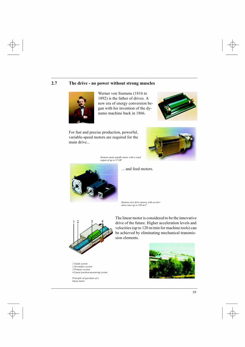
2.7 The drive - no power without strong muscles
Werner von Siemens (1816 to 1892) is the father of drives. A new era of energy conversion be-gan with his invention of the dy-namo machine back in 1866.
For fast and precise production, powerful, variable-speed motors are required for the main drive...
... and feed motors.
The linear motor is considered to be the innovative drive of the future. Higher acceleration levels and velocities (up to 120 m/min for machine tools) can be achieved by eliminating mechanical transmis-sion elements.
Siemens axis drive motors with acceler-ation rates up to 450 m/s2
Siemens main spindle motor with a rated output of up to 37 kW
1 Guide system2 Secondary section3 Primary section4 Linear position measuring system
Principle of operation of a linear motor
19

3 Work must be planned
3.1 The NC program - how do I tell my machine?
Whether yesterday’s punched tape ...
...even today, nothing moves without clear instructions which the control sys-tem understands.
... or tomorrow’s voice instruc-tions ...
20

3.2 Thoughts in motion
Consider the following task: The milling tool has to rotate clockwise with a speed of 1650 revolutions per minute.
Initially it should travel vertically downwards to a depth of 10 mm and the tool should then mill the com-
plete right-hand longitudinal side to produce a smooth, shiny workpiece surface. This is achieved using a feed velocity of 100 millimeters per minute. The tool should then re-tract quickly to the initial
position. Ready!
As usual, there are various ways of achieving this goal: One of the shortest ways is a "special" language which the machine tool specialist calls DIN 66025.
The task mentioned above is defined as follows in this language:
N1 F100 S1650 T24 M3 N2 G0 Z-10 N3 G42 N4 G1 X0 Y15 N5 G1 X74,3 N5 G40 N6 G0 Z100 M30
This widely established language is really very abstract. Furthermore, for workpieces with complex shapes its limits are quickly reached and points must
be calculated. Today, it is far faster and simpler to usegraphic programming.
You will clearly see this on the following pages with the
Siemens control operator
interfaces ShopMill and
ShopTurn.
21

3.3 Where it all happens: Room for motion
Not every workpiece fits every machine.
The maximum workpiece dimensions correspond to the possible traversing path of the tool in the particular axis.
Max. turning diameter Axis X
Max. turning length Axis Z
Max. workpiece length Axis X
Max. workpiece width Axis Y
Max. workpiece height Axis Z
Flatbed machine
(all the following displays refer to this machine type)
Inclined bed machine
(ShopTurn is used on most of these machine types)
22

3.4 Straight to the point
There are several reference points on every CNC machine which are extremely important for program execution.
The manufacturer defines the machine zero M and this cannot be changed. It is located at the origin of the machine coordinate system.
The workpiece zero W (also known as program zero) is at the origin of the workpiece coordinate system. It can be freely se-lected, and should be located at the point where most of the di-mensions originate in the drawing.
The reference point R is approached to set the measuring sys-tem to zero, as the machine zero point can generally not be ap-proached. The control starts to count in its incremental position measuring system.
After they have been installed, all tools have a fixed measured ref-erence point. The control system must know dimensions X and Z, and R and L so that each of these different dimensions can be taken into account when positioning.
Maschinezero M
Workpiece zero W
Reference point R
23
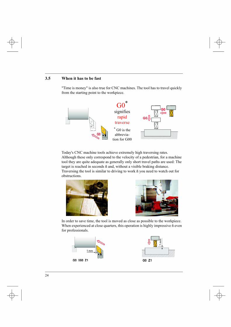
3.5 When it has to be fast
"Time is money" is also true for CNC machines. The tool has to travel quickly from the starting point to the workpiece.
G0*signifies
rapidtraverse
* G0 is the abbrevia-
tion for G00
Today's CNC machine tools achieve extremely high traversing rates. Although these only correspond to the velocity of a pedestrian, for a machine tool they are quite adequate as generally only short travel paths are used: The target is reached in seconds ñ and, without a visible braking distance. Traversing the tool is similar to driving to work ñ you need to watch out for obstructions.
In order to save time, the tool is moved as close as possible to the workpiece. When experienced at close quarters, this operation is highly impressive ñ even for professionals.
24

4 How workpieces are formed ...
4.1 Contours consist of straight lines and arcs
Turned and milled workpieces and therefore their contours can generally be de-fined using straight lines and arcs.
Each arc can be produced from the left or from the right, similar to a curve in traffic, which, depending on the direction of travel, is either a right-hand or left-hand arc.
Contour of a turned part
Contour of a milled part
25

4.2 How straight lines are programmed according to DIN
According to DIN 66025, all straight lines are programmed using function G1 (short form of G01). In this case, the end point in X and Z is generally specified using absolute coordinates.
The starting point of the contour is X0 / Z0.
G1 X20 Start of the chamfer (24-2*2)
G1 X24 Z-2
G1 Z-28 Start of the arc (30-2)
Arc
G1 X36 Start of the arc (40-2*2)
Arc
G1 Z-40
Arc
G1orG91 G1
Z-70
Z-10
Absolute ("ABS")
G91 stands for incremental ("INC")
(G90)G1 X60 Z-75,774 Value U can be determined using the tangent function as DIN does not permit any angles to be entered.
G1 Z-100
26

When milling, axes X and Y are programmed with function G1 (and for depth infeed, also the Z axis).
G1 Y65 Start of the arc (90-25)
Arc
G1 X115 Start of the arc (140-25)
Arc
G1 Y50 This value can be determined using rigonometrical functions
Arc
G1 X100 Y10
G1orG91 G1
X80
X20
Absolute ("ABS")
G91 stands for incremental ("INC")
(G90) Arc
G1 X10
27

4.3 Basics when programming arcs
If an arc is to be programmed, the direction of rotation must first be defined. The following is valid according to DIN:
*Abbreviations for G02 / G03
While this definition is easy to understand for CNC milling machines, there is a "problem" for all CNC-controlled lathes due to the various machine types, i.e. flat-bed or inclined-bed machines:
What is G2, what is G3?
Due to the quite complicated "three-finger rule", derived from the DIN stan-dard, G2 and G3 can also be defined as follows:
• G2 is an inner arc,• G3 is an outer arc.
G2*
Clockwise
G3*
Counter-clockwise
28

When programming arcs, both the end point (and also the direction of rotation) and the center point must be specified.
As when using a compass, the starting point A, the center point M and the final point E must precisely coincide.
coincides does not coincide
The center point M is always specified with reference to the starting point A: The following applies:
• I belongs to X, K belongs to Z.
• In order to define the sign, always look from A to M and compare with the co-ordinate axes.
29

4.4 How arcs are programmed according to DIN
Turned part
Up until now, the individual contour sections were designated in the program with a, s, d etc. However, according to DIN, N1, N2, N3 etc. must be written.
The NC program for the contour above:
N1 G1 X20
N2 G1 X24 Z-2
N3 G1 Z-28
N4 G2 X25 Z-30 I2 K0 K is 0, as the starting and center point have the same Z value.
N5 G1 X36
N6 G3 X40 Z-32 I0 K-2 I is 0, as the starting and center point have the same X value.
N7 G1 Z-40
N8 G2 X40 Z-60 I17,321 K-10 The I value can be calculated using the Pythagorean theorem.
N9 G1 Z-70
N10 G1 X60 Z-75,774 (refer to page 26)
N11 G1 Z-100
30
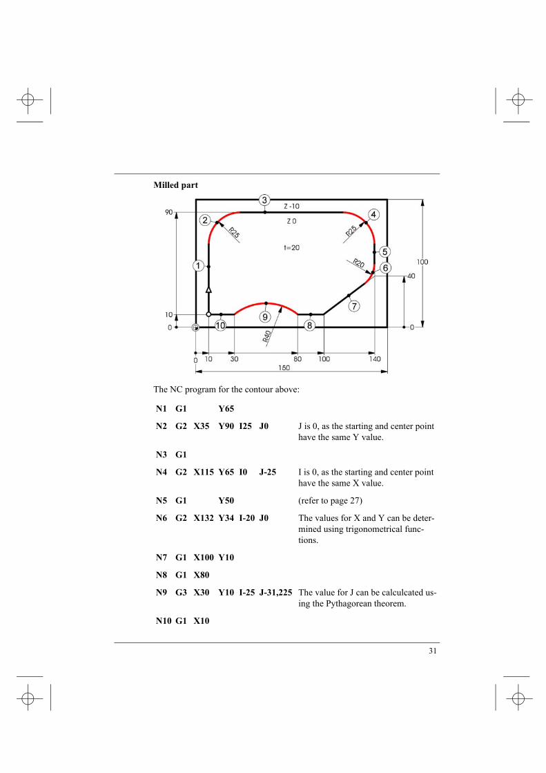
Milled part
The NC program for the contour above:
N1 G1 Y65
N2 G2 X35 Y90 I25 J0 J is 0, as the starting and center point have the same Y value.
N3 G1
N4 G2 X115 Y65 I0 J-25 I is 0, as the starting and center point have the same X value.
N5 G1 Y50 (refer to page 27)
N6 G2 X132 Y34 I-20 J0 The values for X and Y can be deter-mined using trigonometrical func-tions.
N7 G1 X100 Y10
N8 G1 X80
N9 G3 X30 Y10 I-25 J-31,225 The value for J can be calculcated us-ing the Pythagorean theorem.
N10 G1 X10
31

4.5 Graphic programming
On the previous pages, you have seen how difficult it can be to program a con-tour according to DIN.
On the following pages you will see, how simple it is to graphically program contours by way of an example of ShopTurn and ShopMill.
Graphically programming a turning contour with ShopTurn
Graphic programming using ShopTurn is not only simpler, but it is also far faster, especially for complex contours.
The chamfer 2*45° is simply "attached" to the path.
The rounding R2 is simply "attached" to the path.
32

Graphically programming a milling contour using ShopMill
Rounding R25 is simply "attached" to the path.
33

4.6 Contours and tool paths
To obtain a precisely dimensioned workpiece, the tool geometries must be ob-served, both when turning and when milling.
Turning tool
Turning longitudinally and face turn-ing, no dimension deviations occur, in spite of a rounded cutting surface.
Tool path NOT corrected
For taper and also radius turning, di-mension deviations occur if the tool path is not corrected.
Tool path corrected.
Milling tool
However, imagine the milling cutter were to move along the contour with its center point.
Tool path NOT corrected
The larger the radius, the smaller the remaining volume which has to be removed.
Tool path corrected.
34

If the tool is corrected using the control system’s "intelligence" (instead of the tedious tool path calculation in the path in parallel to the contour), then the spe-cialist talks about
Tool nose radius and Cutter radius compensation correction
Compensation or offset correction is implemented using the two functions G41 and G42 :
Direction of motion = direction of view
G41 The tool is located to the left of the contour.
G42 The tool is located to the right of the contour.
G40 cancels G41 and G42.
G41
G42
35

5 ... and how they are produced
5.1 Tools today
When turning and milling, as is true for any cutting operation, the cutting ma-terials and their resistance to wear are especially important. .
Whereas previously alloyed and non-alloyed tool steels dominated, in the sum-mer of 1998, the distribution is as follows:
Carbide metal HSS CBN+PCD (high-alloyed high-speed (cubic boron nitride+
steel tool) polycrystalline diamond) The proportion of ceramic cutting materials is under 1%.
8%33%
59%
Carbide metal
The increasing use of this coated sintered ma-terial means that ma-chining can be performed at extremely high cutting speeds
HSS
Spiral drill, sinker, reamer, ...
Machining is performed at low cutting speeds.
CBN
Suitable for roughing and finishing hardened steel and also for cast iron.
36

Productivity using state-of-the-art toolsUnder the title "Costs reduced - how you can save when cutting", Edition 24 of the PRODUKTION trade periodical of 10.6.98 reported on some insider infor-mation from a machine tool OEM. The report included statements which appeared unbelievable for the "standard" operator:
"Trials at SECO have shown that when finishing cast iron brake disks, ceramic cutting tools had a lifetime of approximately 40 brake disks at a cutting speed of 500 m/min. With the same cutting speed, CBN-30 cutting tools had a lifetime equivalent to 500 brake disks; if the cutting speed is doubled, the tool lifetime was a factor of 6 higher, i.e. 3000 brake disks."
SECO were contacted for an explanation, this is what they said:
"These values come from our experience in the field. We cannot give any de-tailed explanation."
One thing is quite correct, the wear properties when machining grade 25 cast iron with CBN improve the higher the cutting speed.
These "unbelievable" statements can be compared with the "contradictions" of carbide metals:
Individual materials with their particular properties are combined so that a new carbide metal material is formed which only has the required properties of the individual materials.
Titanium/tungsten carbide + Cobalt → Carbide metal
hard soft hardbrittle tough tough
37

The carbide metal inserts are produced for the widest range of materials (steel, cast iron, aluminium) and with a wide range of different geometries. The ma-chining type (coarse or fine machining) also determines the carbide metal type selected.
Comprehensive cutting data cata-logs from all of the tool manufac-turers are available to select the optimal inserts.
38

The clamping system and clamp type depend on the machining situation, the properties of the workpiece and the insert type.
The name reversible insert comes from the fact that these inserts can be re-clamped in the clamp when one of the cutting edges is worn so that a new cut-ting edge is available.
You will find general nominal values for ma-chining using carbide metal inserts in the var-ious books of tables.
39

5.2 Tools in use*
Plunge cutting with a 3 mm wide grooving tool
Longitudinal roughing with a 55° insert
Inner face turning
* The diagrams on this and the next pages are video sequences from the Siemens CD "We belong to the work-shop".
40

Roughing an external contour
Horizontal machining with NC rotary table
Finishing high alloyed steel
41

5.3 When something turns*
The workpiece speed when turning ...
... and the tool speed when milling ...
... are prerequisites for machining.
* The diagrams on this and the next pages are video sequences from the Siemens CD "We belong to the workshop team"
42

5.4 Speed and time
The higher the speed the shorter the time in which the workpiece turns through one complete revolution.
For a speed of n = 30 RPM, one revolution takes 2 seconds.
For a speed of n = 60 RPM, one revolution takes 1 second.
43

5.5 The circumferential speed at different diameters
For a small diameter (and constant speed), the circumferential speed is low.
The circumferential speed can be calculated using the following formula.
v = d * π * n
For a large diameter (and constant speed), the circumferential speed is high.
44

5.6 The circumferential speed at various rotational speeds
With increasing speed (and constant diameter), the circumferential speed in-creases.
The circumferential speed is generally specified in m/min.
For an assumed diameter d = 60 mm (0.06 m), and a speed n = 120 RPM, the following is obtained:
v = d * π * n
v = 0,06m*3,14*120 1/min
v = 22,6 m/min
45

5.7 The cutting speed: when a tool cuts
The cutting speed, unlike the circumferential speed, measures the speed of the tool relative to the workpiece when cutting.
At the same speed n=750 RPM, the cutting speed can be different, depending on the workpiece diameters.
In order to achieve optimum tool use, it must be possible to select various speeds:
Larger diameter = lower speed etc.
46
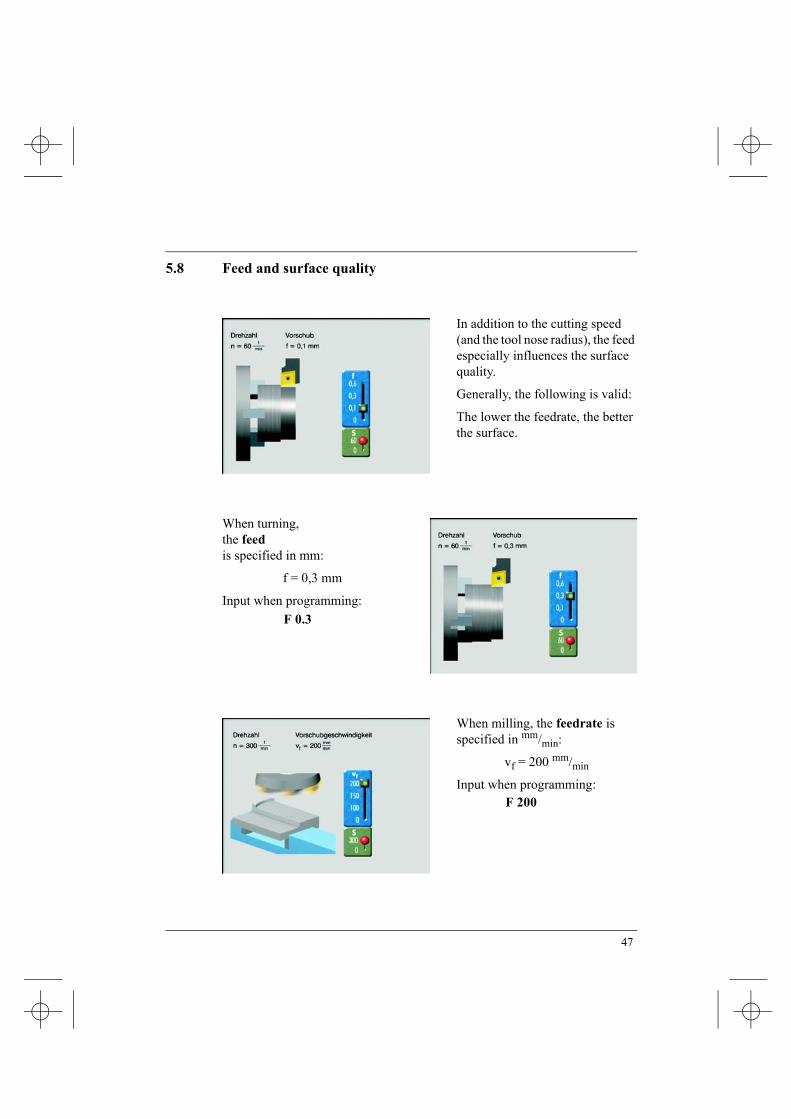
5.8 Feed and surface quality
In addition to the cutting speed (and the tool nose radius), the feed especially influences the surface quality.
Generally, the following is valid:
The lower the feedrate, the better the surface.
When turning, the feed is specified in mm:
f = 0,3 mm
Input when programming:
When milling, the feedrate is specified in mm/min:
vf = 200 mm/min
Input when programming:
F 0.3
F 200
47

5.9 Constant cutting speed manually controlled
When face turning, it is tedious to keep adjusting the speed to maintain an op-timum cutting speed.
At an excessive speed (n = 240 RPM), the tool will be destroyed, at a speed which is too low (n = 60 RPM), the tool will not cut optimally.
At a speed of n = 120 RPM, the tool cuts optimally which means that higher speeds must be selected at an ever increasing rate.
For those who are interested:
would be the in-stantaneous diame-ter at which the tool is cutting.
d vπ n⋅----------=
v d π n⋅ ⋅=
d12000 mm
min----------
3 14, 120 1min----------⋅
------------------------------------=
d 318mm=
48

Constant cutting speed controlled by the control systemFor all CNC lathes, a constant cutting speed can be selected:
The control system calculates the appropriate speed as a function of the partic-ular (actual) diameter.
The operator only has to specify the required cutting speed, in this case,
vc = 120 m/min.
In the specialist’s language, this is known as
The cutting speed (an empirical value or from the book of tables), depends on many parameters, e.g.:
• Tool material• Workpiece material• Required surface quality• Coolant• Machine (stability, ...)• Clamping (projection, ...)
G96 S120
49

6 The optimum technology is important
6.1 Milling with ShopMillIn the following, you will see, using as an example a component from a grind-ing machine, how you can quickly progress from the drawing to your milled part using ShopMill, graphically supported and without requiring any pro-gramming know-how.
50

Before we get goingTo start off with the exercise has to be given a name That is also true for ShopMill programs. But, just like a child, the program isn’t given a run-of-the-mill number, but a real name. Just like everything else in ShopMill.
First, you define the unmachined dimensions, the retraction plane, the safety clearances and the main spindle axis.
51

FacingThe workpiece is to be face machined in the first working step. In this case, a milling cutter has already been recommended for the facing ...
... Of course you can select any other tool from the list. You will find all of the parameters which you require next to the tool names:geometrical and technological values, coolant, compressed air ...The tool usage time is also monitored - the so-called tool life monitoring.
Even so-called replacement tools and flexibly-coded tool magazines can be administered. For oversized tools, the adjacent positions are also automatically taken into account.
52

Help graphics for every data entryLet’s stay with the selected size 63 milling cutter
The cutting data for the facing must now be specified. There is a plain text display for each input field, and if required, a help screen.
This means that you can quickly get to learn ShopMill without any long training period. There is no coding or pro-gramming to learn. All of the inputs are made using input masks with graphic support.
The first machining step has, in the meantime, been transferred into the machining step list.The facing is symbolized using a pictogram. The most important data of particular machining step is always displayed at the side - well arranged and to be read at a glance.
53

Circular pocketThe continuous circular pocket is now to be milled at the center.
You have access to a wide range of plunge strategies. Depending on what your tool can best handle, it can be fed centered, oscillating or in a spiral.You can check your inputs using a simulation graphic.
54

Creating complex contoursSo you reckon this is going to be somewhat more difficult with a complex outer contour?Wrong! Even if your drawing is not dimensioned for NC machi-ning, ShopMill’s contour computer and the graphic display are there to support you.Rounding-off and chamfers are absolutely no problem. They are simply "attached" to the previous element.
It doesn’t make any difference if dimension in the drawing is specified in absolute or incre-mental terms. You can toggle between them simply by clicking. Furthermore, an integrated calculator can be called up from every input field.
If a contour element is not fully dimensioned, it can be defined using the subsequent elements.As soon as all of the dimensions are known, the graphic is updated. The contour is completely defined in just minutes - without any mathematical operations.
55

Roughing along a contourUsing a size 30 cutter, the workpiece will now be roughed along its contour.
The machining step is simulated.
56

Finishing along a contour
A bracket symbolizes the link between the contour and the machining steps.
The screen shows the finishing operation at an "obvious" position of the workpiece - zoomed-in.
Then the contour is finished using a size 12 milling cutter.
57

Pocket with islandsIn this case, it is the other way around, two contours are linked by one machin-ing operation. The first contour defines a pocket, and the second, an island within this pocket.
Pockets, with up to twelve complex islands can be solid machined parallel with the contour using ShopMill. This includes identifying and removing the residual material, if a large milling cutter was used for roughing. The benefit - you save time!
You can always toggle between the operating steps and the graphics with a simple click.
58

Linking drilling patternsOnce all the milling operations have been completed, it is time to drill.In order to avoid having to change the tool early on, initially, all of the drilling patterns and individ-ual holes are centered. You can also clearly see the linking in this list of machining steps.
The screen shows the input mask for defining a "circle" drilling pattern with help screen.
You can quickly, simply and indi-vidually enter the positions of the holes, pockets, grooves etc., using this mask.
59

Linking drilling operationsA position pattern can be linked with various machining operations.
... but they can also be displayed as a side view.
This allows you to immediately see whether you entered the correct drilling diameter and drilling depths.
All good things come in three’s:In addition to the top view and side view, there is also a help screen for this input mask.
The two technological elements (drilling and thread cutting) not only can be shown as top view to optically check the data entries ...
60

SimulationAfter the last machining step, you can simulate everything once again to check:
Firstly the circular pocket ...
... and then finish this contour with a size 12 milling cutter etc.
... then rough the outer contour with a size 30 milling cutter ...
61

The finished workpiece in 2DThe screen shows a top view of the part after the machining has been completed ...
... or a view from three sides.
62

The finished workpiece in 3DThe 3D screen is especially transparent. Here, you can view the workpiece from various sides, and the cross section.
And as always: After theory, it’s time for practice!
63

6.2 Turning with ShopTurn
In the following, you will see, using a swivel damper from a steering system, as example how you can use ShopTurn to quickly obtain a turned part from the drawing - graphically supported and without any programming know-how.
64

Before we get goingIn the first step, you define the unmachined part type, unmachined part dimension, the retraction plane and the tool change point. Furthermore, you can define the speed limits for up to three spindles.
Initially, the workpiece should be faced. In this case, an 80° lathe tool is already offered for the facing …
65

Tool list... It goes without saying that you could also select any other tool from the list. All of the geometry and technological values which are required are available after the tool name …
… Naturally, you can compensate the tool wear using the fine offsets, and you can monitor the tool lifetime as well as the number of times that the tool is used.
66

FacingAfter the tool has been selected, the technology and geometry data must be en-tered. In this case, when required, there is a clear help display for each display.
Neither coding nor programming is required.
You can start to use ShopTurn with almost any training.
The first machining step has in the meantime, already been included in the working step list. A pictogram symbolizes stock removal with the data for facing The most important technological data of the working step are pro-vided next to it - always precise and transparent.
You can check your entries using the simulation graphics. Here, you can also read the total production time.
67

Creating complex contoursAnd you think that it will be more difficult with the com-plex outer contour? Wrong! If the drawing isn't provided with dimensions for NC ma-chining, then the ShopTurn contour computer comes to your aid..
If the dimension system of your drawing allows various geometrical solutions, …
… then simply graphically select the optimum solution.
68

This means that even complex geometries are quickly created using clear, transparent symbols and easy to understand inputs.
Stock removal against contourThe workpiece is now to be roughed against the contour using the 80° lathe tool.
69

The finishing allowance is set to zero because the contour isn't to be finished.
As the negative gradient contours cannot be machined using the 80° tool, the relief cut field is set to no.
A bracket symbolizes the logic operation between the contour, entered in line N15 and the machining step.
70

SimulationJust like always, the simulation displays the result of your entry …
… and you can clearly see the current workpiece condition in the 3D view.
71

Machining residual materialNow, the negative gradient contours should be machined using the 35° V chisel, because only this tool can remove residual material.
This working step is automatically linked with the contour entered in line N15.
72

Different workpiece views
And, to be on the safe side, simulation…
… with the final 3D display for checking.
You can then obtain a complete overview of your production situation in the 3-window view which is also provided.
73

RechuckingIn addition to a hole and the grooves, two spigots have to be milled on the lefthand side of the workpiece. This is the reason that a new machining plan with a short unmachined part is created.
Making groovesIf you wish to create several, similar grooves, then this does not present a problem. Simply enter the number of grooves and the clearance between them and ShopTurn does the rest for you.
74

Drilling
Also when drilling, for each input field, a help text is displayed at the top next to a help display.
Milling operations on the lathe
No need to worry about milling on a lathe!
Using ShopTurn, it is also quite simple and straight forward. In ad-dition to the simple square spigots shown here, derived from ShopMill, it is also possible to machine complex pockets and islands - both for face as well as the peripheral surfaces!
The process plan with complete machining
This is the work plan …
75

… with the grooving …
… and the hole …
… and with face milling!
The work plan which can be simply created even for com-plex workpieces, in conjunc-tion with such transparent 3D graphics, allows you to even integrate one-chuck machin-ing simply and easily into your production environment.
76

And the chips keep going!
Practice always follows theory …
… practice, which with ShopTurn, is fun - lots of fun!
77

6.3 Detailed quality for the perfect fit
In spite of state-of-the-art production technology, incorrectly dimensioned workpieces can occur due to, for example, worn tools, vibrations etc.
Personnel must check (at least randomly) whether the workpiece corresponds to the specifications in the technical drawing
Measuringthe complete length of 132.15 mm of the work-piece using a caliper
Checkingthe diameter 20,2 ±0,03 mm with a limit gauge
78

In a photo-montage, the mounting location of the damper assembly can be seen within the steering assembly.
The steering assembly shown above is used for this commercial vehicle.
79

Measuring the plate thickness using an external micoro-meter
When measuring, a specific dimension is determined. The measuring accu-racy depends on the measuring device (caliper, external micrometer, ...).
Checkingthe bore with a tolerance-plug gauge
When checking, a specific dimension is not determined. It is determined whether the workpiece is "GOOD" or "WASTE" at the checked location.
80

Installed sealing plate on the drive motor of the grinding disk
Overall view of the tool grinding machine showing the drive motor
81

Index
AAbsolute dimensioning . . . . . . . . . . . . . 26Arc . . . . . . . . . . . . . . . . . . . . . . . . . . . . . 28Axes . . . . . . . . . . . . . . . . . . . . . . . . . . . . 18Axis drive . . . . . . . . . . . . . . . . . . . . . . . 18
BBook of tables . . . . . . . . . . . . . . . . . . . . 39
CCalculator . . . . . . . . . . . . . . . . . . . . . . . 55Caliper . . . . . . . . . . . . . . . . . . . . . . . . . . 78Carbide metal . . . . . . . . . . . . . . . . . . . . 36Carbide metals . . . . . . . . . . . . . . . . . . . . 37CBN . . . . . . . . . . . . . . . . . . . . . . . . . . . . 36Chamfer . . . . . . . . . . . . . . . . . . . . . . 26, 32Checking . . . . . . . . . . . . . . . . . . . . . 78, 80Circle center point . . . . . . . . . . . . . . . . . 29Circle end point . . . . . . . . . . . . . . . . . . . 29Circular pocket . . . . . . . . . . . . . . . . . . . 54Circumferential speed . . . . . . . . . . . 44, 45Clamping holder . . . . . . . . . . . . . . . . . . 39CNC lathes . . . . . . . . . . . . . . . . . . . . . . 15CNC milling machines . . . . . . . . . . . . . 15CNC path control . . . . . . . . . . . . . . . . . 17Cobalt . . . . . . . . . . . . . . . . . . . . . . . . . . 37Commands . . . . . . . . . . . . . . . . . . . . . . . 20Contour . . . . . . . . . . . . . . . . . . . . . . . . . 25Contour computer . . . . . . . . . . . . . . . . . 55Contour milling . . . . . . . . . . . . . . . . . . . 40Control loop . . . . . . . . . . . . . . . . . . . . . . 18Conventional machines . . . . . . . . . . . . . 14Coolant . . . . . . . . . . . . . . . . . . . . . . . . . 49Cross slide . . . . . . . . . . . . . . . . . . . . . . . 12
Cut . . . . . . . . . . . . . . . . . . . . . . . . . . . . . 34Cutting data . . . . . . . . . . . . . . . . . . . . . . 53Cutting edge . . . . . . . . . . . . . . . . . . . . . 39Cutting material . . . . . . . . . . . . . . . . . . . 36Cutting radius compensation . . . . . . . . . 35Cutting speed . . . . . . . . . . . . . . 37, 46, 47Cutting speed, constant . . . . . . . . . . 48, 49
DDimension deviation . . . . . . . . . . . . . . . 34Dimension reference point . . . . . . . . . . 23Dimensions . . . . . . . . . . . . . . . . . . . . . . 10Dimensions of unmachined parts . . . . . 51DIN 66025 . . . . . . . . . . . . . 21, 26, 27, 28Direction of rotation . . . . . . . . . . . . . . . 28Drilling . . . . . . . . . . . . . . . . . . . . . . 60, 75Drilling device . . . . . . . . . . . . . . . . . . . . 12Drilling patterns . . . . . . . . . . . . . . . . . . . 59Dynamo machine . . . . . . . . . . . . . . . . . . 19
EEASYSTEP (mode) . . . . . . . . . . . . . . . . 50Electron tubes . . . . . . . . . . . . . . . . . . . . 16Experience know-how . . . . . . . . . . . . . . 11External micrometer . . . . . . . . . . . . . . . 80
FF address . . . . . . . . . . . . . . . . . . . . . 21, 47Face grooving . . . . . . . . . . . . . . . . . . . . 40Face turning . . . . . . . . . . . . . . . . . . . . . . 40Feed . . . . . . . . . . . . . . . . . . . . . . . . . . . . 47Feed motor . . . . . . . . . . . . . . . . . . . . . . . 19Finishing . . . . . . . . . . . . . . . . . . . . . . . . 41Finishing allowance . . . . . . . . . . . . . . . . 70Flatbed machine . . . . . . . . . . . . . . . 22, 28
82

GG0 . . . . . . . . . . . . . . . . . . . . . . . . . . . . . 24G1 . . . . . . . . . . . . . . . . . . . . . . . . . .26, 27G2, G3 . . . . . . . . . . . . . . . . . . . . . . . . . . 28G40, G41, G42 . . . . . . . . . . . . . . . . . . . 35G90, G91 . . . . . . . . . . . . . . . . . . . . . . . . 26G96 . . . . . . . . . . . . . . . . . . . . . . . . . . . . 49Geometrical functions . . . . . . . . . . .26, 27Graphically programming . . . . . . . .32, 33Groove milling . . . . . . . . . . . . . . . . . . . . 41Grooves . . . . . . . . . . . . . . . . . . . . . . . . . 74
HHelp screen . . . . . . . . . . . . . . . . . . .59, 60HSS . . . . . . . . . . . . . . . . . . . . . . . . . . . . 36
IInclined bed machine . . . . . . . . 22, 22, 28Incremental dimensioning . . . . . . . . . . . 26Incremental position measuring system 23Individual drive . . . . . . . . . . . . . . . . . . . 13Inner arc . . . . . . . . . . . . . . . . . . . . . . . . . 28Inner turning . . . . . . . . . . . . . . . . . . . . . 40Islands . . . . . . . . . . . . . . . . . . . . . . . . . . 58
LLanguage input . . . . . . . . . . . . . . . . . . . 20Lathe . . . . . . . . . . . . . . . . . . . . . . . . . . . 12Leadscrew drive . . . . . . . . . . . . . . . . . . . 18Limit gauge . . . . . . . . . . . . . . . . . . . . . . 78Linear motor . . . . . . . . . . . . . . . . . . . . . 19Linking . . . . . . . . . . . . . . . . . . . . . .59, 60Linking drilling patterns . . . . . . . . . . . . 59Logic operation . . . . . . . . . . . . . . . . . . . 57Longitudinal roughing . . . . . . . . . . . . . . 40
MM3 . . . . . . . . . . . . . . . . . . . . . . . . . . . . . 21
M30 . . . . . . . . . . . . . . . . . . . . . . . . . . . . 21Machine tools . . . . . . . . . . 12, 13, 13, 14Machine zero . . . . . . . . . . . . . . . . . . . . . 23Machining step . . . . . . . . . . . . . . . . . . . 52Main drive . . . . . . . . . . . . . . . . . . . .18, 19Maudsley, Henry . . . . . . . . . . . . . . . . . . 12Measuring . . . . . . . . . . . . . . . . . . . .78, 80Measuring system . . . . . . . . . . . . . . . . . 18Microprocessor . . . . . . . . . . . . . . . . . . . 16Milled part . . . . . . . . . . . . . . . . 25, 26, 27Milling . . . . . . . . . . . . . . . . . . . . . . . . . . 41Milling radius control . . . . . . . . . . . . . . 35Milling tool . . . . . . . . . . . . . . . . . . . . . . 34MIT . . . . . . . . . . . . . . . . . . . . . . . . . . . . 16Modules . . . . . . . . . . . . . . . . . . . . . . . . . 13Motors . . . . . . . . . . . . . . . . . . . . . . . . . . 19
NNC program . . . . . . . . . . . . . . . 11, 19, 30Nurbs interpolation . . . . . . . . . . . . . . . . 17
OOuter arc . . . . . . . . . . . . . . . . . . . . . . . . 28
PPCD . . . . . . . . . . . . . . . . . . . . . . . . . . . . 36Plunge strategies . . . . . . . . . . . . . . . . . . 54Pockets . . . . . . . . . . . . . . . . . . . . . . . . . . 58Point-to-point and path control . . . . . . . 16Programming interface . . . . . . . . . . . . . 17Punched tape . . . . . . . . . . . . . . . . . . . . . 20Pythagoras . . . . . . . . . . . . . . . . . . . . . . . 30
RRapid traverse . . . . . . . . . . . . . . . . . . . . 24Reference point . . . . . . . . . . . . . . . . . . . 23Reference points . . . . . . . . . . . . . . . . . . 23Relay technology . . . . . . . . . . . . . . . . . . 16
83

Repeat accuracy . . . . . . . . . . . . . . . . . . . . 8Replacement tools . . . . . . . . . . . . . . . . . 52Residual material . . . . . . . . . . . . . . . 59, 72Rotation . . . . . . . . . . . . . . . . . . . . . . 42, 43Roughing . . . . . . . . . . . . . . . . . . . . . 40, 41Rounding-off . . . . . . . . . . . . . . . . . . 32, 33
SS address . . . . . . . . . . . . . . . . . . . . . 21, 42Semiconductor memory . . . . . . . . . . . . 16ShopMill . . . . . . . . . . . 17, 33, 50, 51, 52ShopTurn . . . . . . . . . . . . . . 17, 32, 32, 64Siemens, Werner von . . . . . . . . . . . . . . 19Simulation . . . . . . . . . . . . . 56, 57, 58, 61Sinter materials . . . . . . . . . . . . . . . . . . . 36SINUMERIK . . . . . . . . . . . . . . . . . . 16, 17Speed . . . . . . . . . . . . . . . . . 19, 42, 42, 43Spindle lathe . . . . . . . . . . . . . . . . . . . . . 12Steam engine . . . . . . . . . . . . . . . . . . . . . 12Straight lines . . . . . . . . . . . . . . . . . . 26, 27Surface quality . . . . . . . . . . . . . . . . . 10, 47
TT address . . . . . . . . . . . . . . . . . . . . . . . . 21Tangential function . . . . . . . . . . . . . . . . 26Technical drawing . . . . . . . . . . . . . . . . . 10Technological values . . . . . . . . . . . . . . . 52Titanium carbide . . . . . . . . . . . . . . . . . . 37Tolerance-plug gauge . . . . . . . . . . . . . . 80Tool grinding machine . . . . . . . . . . . . . 81Tool life monitoring . . . . . . . . . . . . . . . 52Tool list . . . . . . . . . . . . . . . . . . . . . . 52, 66Tool manufacturer . . . . . . . . . . . . . . . . . 37Tool paths . . . . . . . . . . . . . . . . . . . . 34, 35Tool steels . . . . . . . . . . . . . . . . . . . . . . . 36Tools . . . . . . . . . . . . . . . . . . . . . . . . 36, 37Transmission belts . . . . . . . . . . . . . . . . . 13Tungsten carbide . . . . . . . . . . . . . . . . . . 37Turned part . . . . . . . . . . . . . . . 25, 26, 27Turning . . . . . . . . . . . . . . . . . . . . . . . . . 40
Turning tool . . . . . . . . . . . . . . . . . . . . . . 34Turnplates . . . . . . . . . . . . . . . . . . . . 37, 39
WWaste . . . . . . . . . . . . . . . . . . . . . . . . . . . 80Watt, James . . . . . . . . . . . . . . . . . . . . . . 12Work plan . . . . . . . . . . . . . . . . . . . . . . . 57Workpiece programming . . . . . . . . . . . . 16Workpiece zero . . . . . . . . . . . . . . . . . . . 23
84

Diagrams/Photographs
We would like to thank the following companies and institutions, who provided us with the photographs on the following pages.
B Boehringer, Göppingen . . . . . . . . . . . . . . . . . . . . . . . . . . . . . . . . . . . . . . . 15
Bridgeport, Weiterstadt . . . . . . . . . . . . . . . . . . . . . . . . . . . . . . . . . . . . . . . 15
D Deutsches Museum, München . . . . . . . . . . . . . . . . . . . . . . . . . . . 12, 13, 14
Deutsches Werkzeugmuseum/Historisches Zentrum, Remscheid 12, 13, 14
DMG, Bielefeld . . . . . . . . . . . . . . . . . . . . . . . . . . . . . . . . . . . . . . . . . . . . . 15
H Hanser-Verlag, München . . . . . . . . . . . . . . . . . . . . . . . . . . . . . . . . . . . . . . 9
Hochschuldidaktisches Zentrum der RWTH Aachen . . . . . . . . . . . . . . . . 10
I Index, Esslingen . . . . . . . . . . . . . . . . . . . . . . . . . . . . . . . . . . . . . . . . . . . . 15
Iscar, Ettlingen . . . . . . . . . . . . . . . . . . . . . . . . . . . . . . . . .36, 38, 39, 40, 41
K Klingelnberg, Hückeswagen . . . . . . . . . . . . . . . . . . . . . . . . . . . . . 10, 11, 81
Konradin-Verlag / INDUSTRIE Anzeiger, Leinfelden-Echterdingen . . . 19
L Laboratorium für Werkzeugmaschinen und Betriebslehre der RWTH Aachen . . . . . . . . . . . . . . . . . . . . . . . . . . . . . . . . . . . . . . . . 7, 20
M Mercedes-Benz Lenkungen GmbH, Düsseldorf . . . . . . . . . . . . . . 10, 11, 81
N NC-Verlag, Hannover . . . . . . . . . . . . . . . . . . . . . . . . . . . . . . . . . . . . . . . . . 9
S Sandvik, Düsseldorf . . . . . . . . . . . . . . . . . . . . . . . . . . . . .36, 38, 39, 40, 41
Seco, Düsseldorf . . . . . . . . . . . . . . . . . . . . . . . . . . . . . . . .36, 38, 39, 40, 41
V Verlag Europa-Lehrmittel, Haan-Gruiten . . . . . . . . . . . . . . . . . . . . . . . . . 39
85