single slot smt connectors for card-bus based pc … sheets/hirose pdfs...a2 single slot smt...
TRANSCRIPT

A2
Single Slot SMT Connectors for Card-Bus Based PC CardsIC14 Series PC Card Standard Compliant
Board Space-Saving
Secure board retention
Three-stage “Pop-Up” card ejection mechanism
Two anchoringpins
When the eject button is mistakenly pressed without a PC card inserted
Protruding button isvulnerable to damage.
Existing products IC14
Four metal fittings
Equipmentoutline
SMT Unit
SMT Unit
Guide Unit
■ Features 1. Space-Saving design facilitates pattern routing
Responding to the need for the equipment miniaturization,the board mounting area has been further reduced byrelocation of the mounting screws away from the possiblerouting of the conductive traces.
2. Card insertion shock protectionTotal of 6 board retention points assures that there is notransfer of card insertion forces to the solder terminations.
3. New “Pop-Up” button card ejection mechanismThe button does not protrude without the card beinginserted, preventing it’s damage when carrying thenotebook computer.
4. Customized ejection buttons The configuration, color or length can be designed forcustomer’s specific applications.
5. Reliable and balanced card ejection mechanismHirose’s unique ejection mechanism will apply force equallyat each edge of the inserted card. In addition, large distanceof the ejection allows easy hold on the card.
■ Applications Notebook PCs, audio/video equipment and other devicesutilizing PC cards.
Board mounting Standoff Eject button
Standard
Reverse
1.5mm
2.2mm
2.2mm
Left
RightLeft
Right
Right
Right
Left
Left
Pop-upFoldingRigid
Pop-upPop-upPop-upPop-upFoldingRigid
Pop-upPop-upFoldingRigid
Pop-up

A3
500 V DC 500 V AC / one minute1mA DC Frequency: 10 to 2000 Hz, single amplitude of 1.52 mm oracceleration of 147m/s2 (peak), 4 hours / 3 axis96 hours at temperature of 40ç±2ç and humidity of 90% to95%Temperature: -55ç / +5ç to +35ç / +85ç / +5ç to +35çDuration: 30 / +5 max. / 30 / +5 max. (Minutes)5 cycles10000 cycles at 400 to 600 cycles per hour
Reflow: At the recommended temperature profile Manual soldering: 300ç for 3 seconds
1000 Mø min.No flashover or insulation breakdown.60 mø max. (Initial value)No electrical discontinuity of 100 ns or more.
Insulation resistance: 100 Mø min.
Insulation resistance: 100 Mø min.
Contact resistance: 20mø max. from initial value
No deformation of any component. No affect oncontacts.
1. Insulation resistance2. Withstanding voltage3. Contact resistance 4. Vibration
5. Humidity
6. Temperature cycle
7. Durability(mating/unmating)
8. Resistance to soldering heat
Ratings
0.5A
125V AC
Operating temperature
range
Operating humidity
range
Current
rating
Voltage
rating
-55ç to +85ç (Note 1)
Relative humidity 95% max.
(No condensation)
Storage temperature
range
Storage humidity
range
-40ç to +70ç (Note 2)
40% to 70% (Note 2)
■ Product Specifications
Item Specifications Conditions
Note 1: Includes temperature rise caused by current flow.Note 2: The term ”storage” refers to products stored for long period of time prior to mounting and use. Operating Temperature Range
and Humidity range covers non- conducting condition of installed connectors in storage, shipment or during transportation.
■ Materials/Finish
Component
Insulator
Contacts
Ground/eject metal fittingsPositioning pin
Material Finish Remarks
Heat resistant thermoplastic compound
Brass
StainlessBrass
Color: BlackContact area: Gold platedTermination area: Tin-lead plated (Note)
----------Tin-lead plated (Note)
UL94V-0
----------
--------------------
SMT unit
Guide unitComponent
InsulatorCover/Eject metal fittings
Spring
Material Finish Remarks
PBTStainless
Steel
Color: Black--------------------
UL94V-0--------------------
Note: Lead-free specified connectors are tin plated.

A4
■ Ordering information● SMT unit
● Guide unit
Series name : IC14Standoff type
Blank : 0 mm A : 2.2 mm B : 1.5 mm
Board mounting typePL: Standard typePLR: Reverse type
SF : SMT unitEject button positionEJR : Right-side eject EJL : Left-side eject Number of ground contacts Product specification code Blank : Tin-lead plated(71): Lead-free plated
12
3
45
6
Series name : IC14 Standoff type
Blank : 0 mm A : 2.2 mm B : 1.5 mm (Note 1)
G: Guide unite
Eject button type Blank : Rigid button P : Pop-up button F : Folding button
Eject button position EJR: Right-side eject EJL: Left-side eject
7
1 72 85
8
9
IC14 A - PLR - SF - EJR -(71)1 2 3 64 5
IC14 A - G - P EJR7 8 9 10
10
11
11
11
Note 1: In the IC14B type, the screw attachment holes in the Guide unit are not threaded. Note 2: In this series the SMT unit and the Guide unit must be used in combinations shown below. Note 2: Other combinations cannot be used.
* Series name ( ⇔ ) * Standoffs ( ⇔ ) * Ejection button position ( ⇔ )

A5
1 : All illustrations show the SMT unit (1) and Guide unit (2) assemblied.
2 : Dimensions for card insertion are in accordance with “PC card standard”.
3 : Indicated dimensions are symmetrical to the center of the card insertion slot.
Right Pop-up button● IC14, IC14A
● IC14B
PRBM3
SBR
3
SMT unit(1)
3
3
84.5
5(E
ject
or b
utto
n pu
shed
-in
for
with
draw
al)
85.8
(Car
d fu
lly in
sert
ed)
( 7.4
)
Eject metal components movable range
SAR
PRA
Guide unit(2)
#2-M2(2X) 61.8
58.9
3.3
6
63.5
32.6
74.5
62.5
527.45
57.4
32MAX
No.34 No.68GND
5.5M
AX7.
5MA
X
GND
Button position for card ejection
GND
No.1GND
No.35No.2No.36
30.55
No.1 No.2
No.36No.35
No.34
No.68
C
4.8
3.5
B
A
2.522.8
62.6
43.8
2.5
5
5
Stand off height
2.2mm
1.5mm
CL640-1301-0
CL640-1303-6
CL640-1309-2
IC14-PL-SF-EJR
IC14A-PL-SF-EJR
IC14B-PL-SF-EJR
CL640-1409-7
CL640-1411-9
CL640-1413-4
IC14-G-PEJR
IC14A-G-PEJR
IC14B-G-PEJR
2.7
4.9
4.2
5.5
7.7
7
0.3
2.5
1.8
13.1
13.5
13.3
SMT unit 1
CL No.Part Number
Guide unit 2 A(mm)
B(mm)
C(mm)
Weight (g)CL No.Part Number
■ Standard

A6
1 : All illustrations show the SMT unit (1) and Guide unit (2) assemblied.
2 : Dimensions for card insertion are in accordance with “PC card standard”.
3 : Indicated dimensions are symmetrical to the center of the card insertion slot.
Left Pop-up button● IC14, IC14A
● IC14B
SMT unit(1)
Guide unit(2)
3
B
5.5M
AX7.
5MA
X
32MAX
GND
57.4
GND GND
GND
Eject metal components movable rangeC
6
SAL
P L A
No.35 No.36
No.2No.1 No.34
No.68
No.1 No.35No.2No.36
No.34No.68
85.8
( Car
d fu
lly in
sert
ed)
( 7.4
)
84.5
5(E
ject
or b
utto
n pu
shed
-in
for
with
draw
al)
32.6
4.8
61.8
58.9
62.5
5
30.55
3.3
27.45
74.5
A
63.5
3.5
3
3
62.6
5
2.522.8
43.8
2.5
SBL
PLBM9
#2-M2(2X)
Button position for card ejection
Stand off height
2.2mm
1.5mm
CL640-1302-3
CL640-1304-9
CL640-1310-1
IC14-PL-SF-EJL
IC14A-PL-SF-EJL
IC14B-PL-SF-EJL
CL640-1410-6
CL640-1412-1
CL640-1414-7
IC14-G-PEJL
IC14A-G-PEJL
IC14B-G-PEJL
2.7
4.9
4.2
5.5
7.7
7
0.3
2.5
1.8
13.1
13.5
13.3
SMT unit 1
CL No.Part Number
Guide unit 2 A(mm)
B(mm)
C(mm)
Weight (g)CL No.Part Number
■ Standard

A7
Right Pop-up button
SMT unit(1)
A
B
No.35
4.8
3.5
No.1No.2
No.36
No.34
No.68
63.5
32.6
61.8
58.9
84.5
5(E
ject
or b
utto
n pu
shed
-in
for
with
draw
al)
85.8
30.55
GND
5.5M
AX
7.5M
AX
C
32MAX
No.1GND
No.35No.2
No.36GND
No.34No.68
6
57.4
GND
74.5
62.5
5
27.45
3.3
Guide unit(2)
(Car
d fu
lly in
sert
ed)
Eject metal components movable range
(7.4
)
P R A
R A
3
3
3
Button position for card ejection
Stand off height
2.2mm CL640-1307-7IC14A-PLR-SF-EJR CL640-1411-9IC14A-G-PEJR 4.9 7.7 2.3 14.3
SMT unit 1
CL No.Part Number
Guide unit 2 A(mm)
B(mm)
C(mm)
Weight (g)CL No.Part Number
■ Reverse
1 : All illustrations show the SMT unit (1) and Guide unit (2) assemblied.
2 : Dimensions for card insertion are in accordance with “PC card standard”.
3 : Indicated dimensions are symmetrical to the center of the card insertion slot.

A8
Left Pop-up button type
32Eject metal components movable range
(Car
d fu
lly in
sert
ed)
(7.4
)
Guide unit(2)
SMT unit(1)
5.5M
AX7.
5MA
X
MAX
No.1
GND
GND
No.35No.2
No.36 GND
GND
No.34No.68
57.4
85.8
84.5
5(E
ject
or b
utto
n pu
shed
-in
for
with
draw
al)
32.6
61.8
58.9
62.5
5
30.55
3.3
27.45
74.5
63.5
C
No.1No.2No.34
No.35No.36No.68
B4.8
A
3.5
6
3
3
3
L A
P L A
Button position for card ejection
Stand off height
2.2mm CL640-1308-0IC14A-PLR-SF-EJL CL640-1412-1IC14A-G-PEJL 4.9 7.7 2.3 14.3
SMT unit 1
CL No.Part Number
Guide unit 2 A(mm)
B(mm)
C(mm)
Weight (g)CL No.Part Number
■ Reverse
1 : All illustrations show the SMT unit (1) and Guide unit (2) assemblied.
2 : Dimensions for card insertion are in accordance with “PC card standard”.
3 : Indicated dimensions are symmetrical to the center of the card insertion slot.

A9
Left folding button
C
3
SAL5.
5MAX
7.5M
AX
32MAX
GND
57.4
GND
GND
No.1 No.35
No.2No.36
No.34No.68
Eject metal components movable range
4.8
L A
6
( 93.
6)
Car
d fu
lly in
sert
ed:8
5.6
42.05
61.8
58.9
62.5
5
3.3
27.45
(65.45)
5
8
34.55
Ejecto
r pus
hed-
in for
with
drawa
l:( 9.5)
74.5
3
3
B
No.35 No.36
No.2No.1 No.34
No.68
A
GND
Button position for card ejection
Guide unit(2)
SMT unit(1)
Stand off height
2.2mm
CL640-1302-3
CL640-1304-9
IC14-PL-SF-EJL
IC14A-PL-SF-EJL
CL640-1406-9
CL640-1408-4
IC14-G-FEJL
IC14A-G-FEJL
2.7
4.9
5.5
7.7
0.3
2.5
13.9
14.1
SMT unit 1
CL No.Part Number
Guide unit 2 A(mm)
B(mm)
C(mm)
Weight (g)CL No.Part Number
■ Standard
1 : All illustrations show the SMT unit (1) and Guide unit (2) assemblied.
2 : Dimensions for card insertion are in accordance with “PC card standard”.
3 : Indicated dimensions are symmetrical to the center of the card insertion slot.

A10
Left folding button
SMT unit(1)
Guide unit(2)
No.1No.2No.34
No.35No.36No.68
L A
L A5.
5MAX
7.5M
AX
32MAX
No.1
57.4
GND
No.35No.2
No.36GND
GND
No.68
Eject metal components movable range
6
( 93.
6)
Car
d fu
lly in
sert
ed:8
5.6
42.05
61.8
58.9
62.5
5
3.3
27.45
(65.45)
5
8
34.55
Ejec
tor p
ushe
d-in
for w
ithdr
awal:
( 9.5
)
4.8
74.5
A
B
C
3
3
3
GND
No.34
Button position for card ejection
Stand off height
2.2mm CL640-1308-0IC14A-PLR-SF-EJL CL640-1408-4IC14A-G-FEJL 4.9 7.7 2.3 14.9
SMT unit 1
CL No.Part Number
Guide unit 2 A(mm)
B(mm)
C(mm)
Weight (g)CL No.Part Number
■ Reverse
1 : All illustrations show the SMT unit (1) and Guide unit (2) assemblied.
2 : Dimensions for card insertion are in accordance with “PC card standard”.
3 : Indicated dimensions are symmetrical to the center of the card insertion slot.

A11
Left rigid button
3
8
57.4
C
6
85.6
( Car
d fu
lly in
sert
ed)
4.8
3.5
A
B
32.6
61.8
58.9
62.5
5
3.3
27.45
74.5
63.5
3
3
L A
SAL
No.34
No.68No.36No.35
No.2No.1
GND7.
5MA
X5.
5MAX
Eject metal components movable range
GND
32MAX
No.36No.2
No.35No.1
GND No.34 No.68GND
SMT unit(1)
Guide unit(2)
Stand off height
2.2mm
CL640-1302-3
CL640-1304-9
IC14-PL-SF-EJL
IC14A-PL-SF-EJL
CL640-1402-8
CL640-1404-3
IC14-G-EJR
IC14A-G-EJR
2.7
4.9
5.5
7.7
0.3
2.5
13.4
13.7
SMT unit 1
CL No.Part Number
Guide unit 2 A(mm)
B(mm)
C(mm)
Weight (g)CL No.Part Number
■ Standard
1 : All illustrations show the SMT unit (1) and Guide unit (2) assemblied.
2 : Dimensions for card insertion are in accordance with “PC card standard”.
3 : Indicated dimensions are symmetrical to the center of the card insertion slot.

A12
Left rigid button
SMT unit(1)
Guide unit(2)
3
8
No.1No.2
No.35No.36No.68
FL
L A
57.4
L A
5.5M
AX7.
5MA
X
32MAX
No.1
GND
GND
No.35No.2
No.36 GND
GND
No.34No.68
C
6
Eject metal components movable range
85.6
( Car
d fu
lly in
sert
ed)
C4.8
3.5
A
B
32.6
61.8
58.9
62.5
5
3.3
27.45
74.5
63.5
3
3
No.34
■ Reverse
Stand off height
2.2mm CL640-1308-0IC14A-PLR-SF-EJL CL640-1404-3IC14A-G-EJL 4.9 7.7 2.3 14.4
SMT unit 1
CL No.Part Number
Guide unit 2 A(mm)
B(mm)
C(mm)
Weight (g)CL No.Part Number
1 : All illustrations show the SMT unit (1) and Guide unit (2) assemblied.
2 : Dimensions for card insertion are in accordance with “PC card standard”.
3 : Indicated dimensions are symmetrical to the center of the card insertion slot.

A13
BPCB mounting pattern
● Standard
● Without Standoff (Left button)
● Standoff 1.5mm (Left button)
● Standoff 2.2mm (Common to both Right & left buttons)
● Standoff 1.5mm (Right button)
● Without Standoff (Right button)
4.25±0.05
52.2MAX
55.2MIN
54.65±0.05
53.9MIN
52.2MAX
No conductive traces
59.1
MA
X32.5
MIN
14.4
MA
X
2-Ø2.2 2-Ø2.2+0.1+0
2.95MIN
No conductive traces
5.65
MIN
C
4.3M
IN
12.2
25±
0.05
3.55
±0.
1
4.025±0.05
54.425±0.05
2.5±0.1
GND
GND
Mounting area
58.9±0.05
1.95MIN
(2.2
)
64.7
5±0.
05
Card edge position
Shield plate mounting area
50.4±0.05
2
2-Ø2.2 2-Ø2.2+0.1+0
1.8MAX3.5MIN
54.65±0.05
4.8MIN
1.8MAX
Card edge position
No conductive traces
14.4
MA
X
32.5
MIN
59.1
MA
X
4.25±0.05
2.95MINNo conductive traces
5.65
MIN
C
4.3M
IN
12.2
25±
0.05
3.55
±0.
1
4.025±0.05
54.425±0.05
2.5±0.1
GND
GND
Mounting area
58.9±0.05
1.95MIN
(2.2
)
64.7
5±0.
05
Shield plate mounting area
50.4±0.05
2
59.2MIN53.2MAX12
.225
±0.
053.
55±
0.1
4.025±0.05 54.425±0.05 2.5±0.1
GND
GND
Mounting area
No conductive traces
4.2±0.05
48±0.05
(2.2
)
64.8
±0.
05
Card edge position
50.4±0.05
3.5MIN4.4MAX
3.5
MIN
4.4MAX
56.9MIN
No conductive traces C
43.8±0.05
Shield plate mounting area
21±0.05
2
50.4±0.05
3.8
MIN
No conductive traces
7.75
MIN
7MIN2.6MAX
2.6MAX
2
2
3.5
MIN
11.5
MAX
14.6
MIN
3.5MIN
3.5
MIN
3.8
MIN
7.75
MIN
7MIN 2.6MAX
2.6 MAX
56.9MIN
2
2
59.2MIN53.2MAX
12.2
25±
0.05
3.55
±0.
1
4.025±0.05 54.425±0.05
GND
No conductive traces
43.8±0.05
2.4±0.05
46.2±0.05
(2.2
)
64.8
±0.
05
Card edge position
22.8±0.05
2
No conductive traces
4.4MAX
No conductive traces
3.5
MIN
C
2.5±0.1
GND
Mounting area
11.5
MAX
14.6
MIN
Shield plate mounting area
3.5MIN 3.5MIN4.4MAX
2-Ø2.2 +0.1+0
2-Ø2.2 +0.1+0
Note 1) area show the conductive pattern prohibited area.
Note.2) Indicated dimensions are symmerical to the center of the card insertion slot.
2.95MIN
No conductive traces
Card edge position
No conductive traces
7.25
MIN
3.75
MIN
1.5MAX
1.5MAX
5.65
MIN C
4.3M
IN
2-Ø2.2+0.1 0
59.2MIN
53.2MAX
12.2
25±0
.05
3.55
±0.
1
4.025±0.05 54.425±0.052.5±0.1
GND
GND
Mounting area
11.5
MAX
14.6
MIN
58.9±0.05
1.95MIN 4.05MIN
4.25±0.05 54.65±0.05
(2.2
)
64.7
5±0.
05
Shield plate mounting area
50.4±0.05
2
2
2
2

A14
● Reverse● Standoff 2.2mm
(Common to both Right & left buttons)
● Reverse● Standoff 2.2mm
● Standard● Without Standoff
BPCB mounting area (Enlarged views)
C Ø1.85±0.05(Plated through hole) Ø1.8±0.05(Plated through hole)
4.4±
0.1
Ø2.3
Ø2.35
3±0.
1
2±0.1
( Ter
mina
l mou
nting
area
)
4.2±0
.1(Te
rmina
l mou
nting
area
)
4.4±
0.1
No.34No.35
1.9±0.1
3±0.
1GND
No.1 No.68
GND
2.2±0.05
3.9275±0.05
46.4725±0.05
48.2±0.05
68-0.37±0.03
P=0.635±0.03
No.2
C
2
1.05MIN
2.7M
IN
4.2M
IN
58.4MIN
1.05MINNo conductive traces
Ø1.8±0.05(Plated through hole)
4.4±
0.1
Ø1.85±0.05(Plated through hole)
Ø2.3
Ø2.35
3±0.
1
2±0.1
( Ter
mina
l mou
nting
area
)
4.2±0
.1(Te
rmina
l mou
nting
area
)
4.4±
0.1
No.35
No.2
No.34
1.9±0.1
3±0.
1GND
No.68No.1
GND
2.2±0.05
3.9275±0.05
46.4725±0.05
48.2±0.05
68-0.37±0.03
P=0.635±0.03
● Standoff 1.5mm, 2.2mm
C1.05MIN
2.7M
IN
4.2M
IN
58.4MIN
1.05MIN
No conductive traces
Ø1.8±0.05(Plated through hole)
4.4±
0.1
Ø1.85±0.05(Plated through hole)
Ø2.3
Ø2.35
3±0.
1
2±0.1
( Term
inal m
ounti
ng ar
ea)
4.2±0
.1(Te
rmina
l mou
nting
area
)
4.4±
0.1
No.35
No.2
No.341.9±0.1
3±0.
1GND
No.68 No.1
GND
2.2±0.05
3.9275±0.05
46.4725±0.0548.2±0.05
68-0.37±0.03
P=0.635±0.03
2
No conductive traces
7.25
MIN
3.75
MIN
1.5MAX
1.5MAX
5.65
MIN C
4.3M
IN
2-Ø2.2+0.1 0
59.2MIN53.2MAX
12.22
5±0.0
5
3.55
±0.
1
4.025±0.05 54.425±0.05 2.5±0.1
GND
GND
Mounting area
11.5
MAX
14.6
MIN
No conductive traces
58.9±0.05
1.95MIN 4.05MIN
4.25±0.05 54.65±0.05
(2.2
)
64.7
5±0.
05
Card edge position
Shield plate mounting area
50.4±0.05
2 2
2
Note 1) area show the conductive pattern prohibited area.
Note.2) Indicated dimensions are symmerical to the center of the card insertion slot.2

A15
BAssembly of units and board placement procedures (1) Mount the SMT unit on the PCB board.
Fig. 1
Fig. 2
Note 1: Verify and make sure that the position of the stroke arm of the SMT unit and the push rod of the Guide unit are at the positions indicatedin Fig. 1. (as delivered).If needed, position them as shown.Correct position of the push rod and the stroke arm is required for correct assembly of both units.
Note 2: Make sure that the SMT unit is positioned securely.Note 3: Soldering will not be possible with the Guide unit attached first.
The Guide unit must be attached and secured to the PCB board AFTER the SMT unit is attached to the PCB.
SMT unit Guide unit
Stroke arm Push rod
PCB
PRBM3
PBR
PAR
SBR
A
Interference Interference
SBR
SBR

A16
Fig. 3
Fig. 3-1
(2) Align both arrow marks (stamped on the shield plate) on the Guide unit with the corresponding grooves on the (mounted on the
board) SMT unit (as illustrated of Fig. 3 and 3-1).
PBR
PRBM3
PAR
SBR
A
Fig. 3-1
Fig. 3-2
Insulator part
Shield plate
Position A Position B
SBR
A
Groove
Gide unit
Arrow mark
SMT unit
PCBFig. 3-2

A17
Fig. 4
Note 3: Place the Guide unit over the installed SMT unit, (exercising caution NOT to touch the spring, push rod or the stroke arm).Ref. Fig.4
PBR
PAR
PRBM3
Guide unit holding areas

A18
Fig. 5
Fully locked
(3) Slide the Guide unit forward until it is locked with the SMT unit.
Fully locked units should be as shown on Fig. 5.
PBR
Slide forward
Spring portion
Slide forward
PRBM3 SBR
PAR
Guide unit holding areas
SMT unit
Shiel plate
Locking area
Visible insulator
No space
SBR

A19
Fig. 6
Note 5: It is assumed that the Guide unit and the SMT unit will be mounted on the same PCB. However, in some applications the Guide unit may bemounted directly on the device’s case/housing. It is critical that the miss-alignment of the Guide unit must be kept within ± 0.15 mm.The side clearance between the case/housing and the shield plate should be 0.15mm minimum. Ref. Fig. 6
Note 6: DO NOT insert/eject the PC card before the SMT unit and the Guide unit are fully mounted and locked, with the push rod and stroke armconnected.
PBR
PRBM3 SBR
PAR
Device case/housing
Note 5. Clearance between body and shield: 0.15 mm minimum.
±0.15
±0.15

A20
Note 7: The IC14 and IC14A assemblies do not require separate hex nuts.Note 8: Hex nuts and screws are required for the IC14B assemblies. Max. length of the screw thread is 1.4mm.
Fig. 8
Fig. 7
(4) The Guide unit should be securely attached with two screws.
PAR
(4-1) IC14 and IC14A Types ••• Fig. 7 (From the bottom of the PCB)
PBR
PAR
(4-2) IC14B Type ••• Fig. 8 (From the top of the PCB)
Screw size Connector type Recommended tightening torque (N•m)
M2∞0.4IC14 type
IC14A and IC14B type
0.12~0.16
0.14~0.18

A21
BRecommended procedure for removal of the Guide unit (1) Remove the 2 screws attaching the Guide unit to the PCB.
(2) Make sure that the stroke arm of the SMT unit and the pushrod of the Guide unit are at the positions indicated in Fig. 1.
Fig. 1
Fig. 2
(3) As illustrated in Fig. 2, the lock between the shield plate and the ribs of the insulated case can be released.
Press the insulator on both side of the installed assembly and carefully slide the Guide unit.P
RB
M3 S
BR
PA
R
PCB
Stroke arm Push rode
Remove screws
PB
R
Guide unit SMT unit
Release pressure points(each side)
Range of retaining position
Press
Press
Release pressure points (each side)
Pull guide unit in this direction
Left side
Right side
Detail A
Pull guide unit in this direction
Shield plate
PR
BM
3 SB
R
PA
R
PB
R

A22
Fig. 4
Note 2: Assure that the push rod remains in its original position. Moving it from this position may cause it to fall-out.
Do not move in this positionOriginal push rod position
PR
BM
3 SB
R
Fig. 3 detail A - enlarged view
Note 1: As illustrated in the enlarged view of Fig. 3, the lock is released by deflecting the insulator approximately 0.5 mm.
Insulator (deflect) Shield plate
Detail A lock release condition
A23
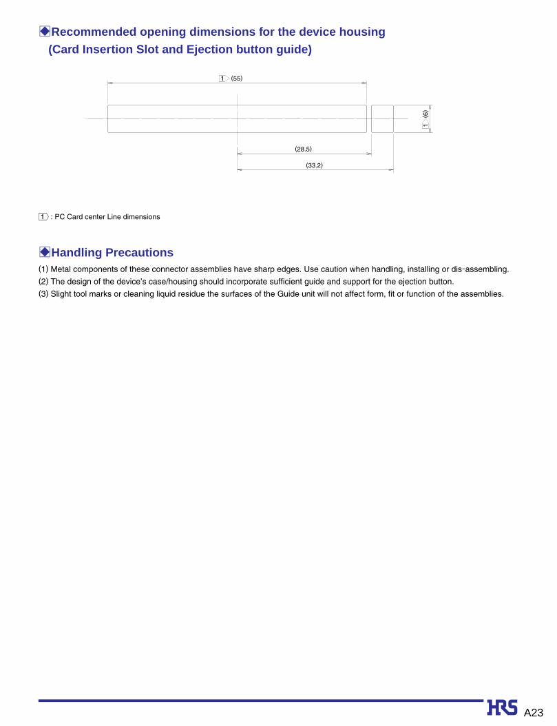
BRecommended opening dimensions for the device housing (Card Insertion Slot and Ejection button guide)
(55)
(28.5)
(33.2)
(6)
1
1
1 : PC Card center Line dimensions
BHandling Precautions (1) Metal components of these connector assemblies have sharp edges. Use caution when handling, installing or dis-assembling.
(2) The design of the device’s case/housing should incorporate sufficient guide and support for the ejection button.
(3) Slight tool marks or cleaning liquid residue the surfaces of the Guide unit will not affect form, fit or function of the assemblies.

A24
BRecommended temperature profileT
empe
ratu
re (
ç)
220ç
60s(MAX)
60~120s
250ç(PEAK)
Start
25ç
150ç
170ç
Time (Seconds)
SolderingPreheating0
50
100
150
200
250
Recommended conditions
Reflow system : IR reflow
Solder composition : Paste, 63%Sn/37%Pb
(Flux content 9wt%)
Test board : Glass epoxy
80mm∞125mm∞1.6mm
thick
Metal mask : 0.15mm thick
Recommended conditions
Reflow system : IR reflow
Solder composition : Paste, 96.5%Sn/3.0%Ag/0.5%Cu
(Flux content 10.5wt%)
Test board : Glass epoxy
80mm∞125mm∞1.6mm thick
Metal mask : 0.15mm thick
The temperature profiles are based on the above conditions.
In individual applications the actual temperature may vary,
depending on solder paste type, volume/thickness and board
size/thickness. Consult your solder paste and equipment
manufacturer for specific recommendations.
● Using Typical Solder Paste
● Using Lead-free Solder Paste
Tem
pera
ture
(ç
)
Time (Seconds)
Start
Preheating Soldering60~90S 20~30S
30S
5S max