single phase induction motor with 4 windings design and
TRANSCRIPT
Single Phase Induction Motor with 4 Windings
Design and Current Control in Auxiliary Winding
Zuriman Anthony
Department of Electrical Engineering
Institut Teknologi Padang
West Sumatra, Indonesia [email protected]
Erhaneli Erhaneli
Department of Electrical Engineering
Institut Teknologi Padang
West Sumatra, Indonesia [email protected]
Fauzan Ismail
Department of Electrical Engineering
Institut Teknologi Padang
West Sumatra, Indonesia [email protected]
Abstract—A single phase induction motor has two windings
for operating. The winding design was more complicated than
the poly-phase induction motor. As a fact that the current
density flowing in each motor winding is not the same for
fluctuating load conditions. Because of that, this study was
aimed to show a new design that simply by using 4 windings in
the stator and the controlled current in auxiliary winding. This
design was focused for capacitor-start capacitor-run induction
motor. The design has 4 windings, one winding act as the main
winding and the other three windings act as the auxiliary
windings. The windings current rating of the proposed motor
was 2.74A and 3.15A for the main and auxiliary winding,
respectively. The auxiliary winding current of the motor was
controlled by the Arduino control system. The performances of
the proposed method were compared to the performances of a
conventional single-phase induction motor that had the same
construction of the stator, rotor and current rating. The
conventional single-phase induction motor used in this study
was a single-phase induction motor of 220V, 8.3A, 4 poles, 1
HP, cage rotor, 1440 RPM, 50Hz. The proposed motor with 4
windings design in this study showed better performances than
the conventional induction motor.
Keywords—4 winding design, single phase induction motor,
current controller, auxiliary winding
I. BACKGROUND
Induction motors are very widely used by society today
in both the industrial and household sectors [1]. The motors
that used in these sectors usually work at 50 Hz or 60 Hz
frequency. Several attempts have been made to improve the
performance of the motor, including by optimally designing
of the rotor slot and stator windings [2] as well as the use of
copper windings in rotor with a smooth rotor geometry [3],
so that the rotor power losses are smaller. Another method
has been developed by using amorphous laminate armor [4],
soft magnetic composite material [5], and the selection of
iron particle size on Fe / silicate magnetic material on soft
magnetic material[6] on the stator to improve the
performance of induction motors. But, all of these methods
are only suitable for motors that work with high frequencies
(400 Hz to 1000 Hz), but not at low frequencies. Single-phase induction motor usually used in household
application. This motor usually used a single phase power system and is produced in low power rating[1]. Motor application is widely used such as washing machine, fans, etc. Single-phase motor has two windings, the main and auxiliary winding, so it has lower efficiency than the poly-phase induction motor. By referring to some researches, the performances of a three-phase induction motor can be
improved by operating it on a single phase power system [7]–[12]. It can be seen that these methods generally applied the principle of a single-phase induction motor to three-phase induction motor by using bank capacitor mounted on the motor. The motor still used 3 windings when operated on a single phase power system, so that the motor would operate close to its power rating. Further research has also been developed by designing a single phase motor using 3 windings such as a three-phase motor design [13]. The research shows that the motor can operated with better performance than conventional single-phase induction motors that had the same stator and a rotor frame design. It had also been developed that single-phase induction motor with 4 identical windings design [14]. By using 4 identical windings, the motor operated with a slightly lower power capacity than the conventional motor and the motor had bad performance while operated on low load condition. Therefore, this study is focused on discussing about a 4 windings design of single-phase induction motor that auxiliary winding current is controlled by the Arduino control system. The object focused on about power factor, output power, and winding current of the motor.
II. CONVENTIONAL SINGLE PHASE INDUCTION MOTOR
Single phase induction motors usually operate by using 2
windings at starting. When the motors use a capacitor bank,
the motors will operate with better performance. This
motors are called capacitor motor [1]. By using the
capacitors, the torque generated by the motor is increased
and the motor work like a two-phase induction motor while
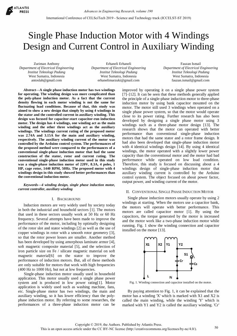
running. Fig. 1 show the winding connection and capacitor
installed on the motor [13].
Fig. 1. Winding connection and capacitor installed on the motor.
By paying attention to Fig. 1, it can be explained that the
motor has a winding 'X' which is marked with X1 and X2 is
called the main winding, while the winding 'Y' which is
marked with Y1 and Y2 is called the auxiliary winding. 'Cr'
International Conference of CELSciTech 2019 - Science and Technology track (ICCELST-ST 2019)
Copyright © 2019, the Authors. Published by Atlantis Press. This is an open access article under the CC BY-NC license (http://creativecommons.org/licenses/by-nc/4.0/).
Advances in Engineering Research, volume 190
50
in Fig. 1 is the run capacitor that used both at starting and
running, while the 'Cs' in Fig. 1 is the start capacitor that
used by the motor at starting only. The 'S1' in Fig. 1 is the
switch that represents the centrifugal switch on the motor,
and the 'N' and „L‟ labels in Fig. 1 are the „Neutral and Line‟
of the voltage source of a single phase power supply
respectively.
III. RESEARCH METHOD
This study is purposed to discuss about a single phase
capacitor motor that has 4 windings design with current
control on auxiliary windings. Three windings acts as a
auxiliary winding and the other windings act as an main
winding. The windings were not identical. The motor had
the main and auxiliary windings with a cross-sectional area
of 0.65 mm2 and 0.75 mm
2 respectively. The main windings
of the motor had a current rating of 2.74 A. In order to
operate the motor with the same current density, the current
rating on the auxiliary winding of the motor is set with a
maximum current of 3.15 A. The motor has the start and run
capacitors of 20 µF and 25 µF, respectively. But, when the
load below 70%, the run capacitor was set 15 µF that is
controlled by using „Arduino Uno control system‟. The
winding connection with the capacitors installed on the
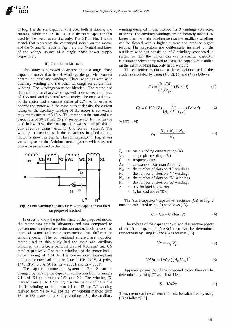
motor is shown in Fig. 2. The run capacitor in Fig. 2 was
varied by using the Arduino control system with relay and
contactor programed to the motor.
Fig. 2 Four winding constructions with capacitor installed
on proposed method
In order to know the performance of the proposed motor,
the motor was test in laboratory and was compared to
conventional single-phase induction motor. Both motors had
identical stator and rotor construction but different in
winding design. The conventional single-phase induction
motor used in this study had the main and auxiliary
windings with a cross-sectional area of 0.65 mm2 and 0.9
mm2 respectively. The main windings of the motor had a
current rating of 2.74 A. The conventional single-phase
induction motor had another data: 1 HP, 220V, 4 poles,
1440 RPM, 8.3 A, 50 Hz, Cs = 200µF and Cr = 30µF.
The capacitor connection system in Fig. 2 can be
changed by moving the capacitor connection from terminals
U1 and X1 to terminals W2 and X2. The winding 'X'
marked from X1 to X2 in Fig. 4 is the main winding, while
the 'U' winding marked from U1 to U2, the 'V' winding
marked from V1 to V2, and the 'W' winding marked from
W1 to W2 ', are the auxiliary windings. So, the auxiliary
winding designed in this method has 3 windings connected
in series. The auxiliary windings are deliberately made 15%
larger than the main winding so that the auxiliary windings
can be flowed with a higher current and produce higher
torque. The capacitors are deliberately installed on the
auxiliary windings consisting of 3 windings connected in
series, so that the motor can use a smaller capacitor
capacitance when compared to using the capacitors installed
on the main winding that only has 1 winding.
The capacitive reactance of the capacitors used in this
study is calculated by using (1), (2), (3) and (4) as follows.
)())((
)18.0(Farad
Vf
ICst
LN
N
)())()((
)(1991.0 FaradVfA
IZCr
LNZ
N
Where [14]:
X
WVUZ
N
NNNA
(3)
IN = main winding current rating (A)
VLN = single phase voltage (V)
f = frequency (Hz)
AZ = constants of Zuriman Anthony
NU = the number of slots on „U‟ windings
NV = the number of slots on „V‟ windings
NW = the number of slots on „W‟ windings
NX = the number of slots on „X‟ windings
Z = 0.6, for load below 70%
= 1, for load above 70%
The „start capacitor‟ capacitive reactance (Cs) in Fig. 2
must be calculated using (3) as follows [13].
)(FaradCrCstCs
The voltage of the capacitor „Vc‟ and the reactive power
of the „run capacitor‟ (VARc) then can be determined
respectively by using (5) and (6) as follows [13].
LNZ VAVc .
2).)(( LNZ VACrVARc
Apparent power (S) of the proposed motor then can be
determined by using (7) as follows[13].
VARcS
Then, the motor line current (IL) must be calculated by using
(8) as follows[13].
Advances in Engineering Research, volume 190
51
LN
LV
SI
The proposed motor will has power factor close to 0.97
when while operate at its standard speed rotation. So, the
power factor of the motor (PF) can be determined by using
(9). And then, the input power (Pin) of the motor can
determined by using (10) as follows.
97,0)( CosPF
)(. CosSPin
IV. RESULT AND DISCUSSION
The conventional motor could not operated properly according to its nameplate data, where the motor did not operate with its standard current at a standard speed of 1440 RPM. Therefore, the motor was operated with a speed close to 1400 RPM. Under these conditions, the proposed motor design was also operated at speeds close to 1400 RPM. Both characteristics of the motors will be discused as follows.
A. Output Power of the Motor
Fig. 3 shows characteristic of the output power as a result from the laboratory.
Fig. 3 Characteristic of the output power of the motors
From Fig. 3 can be seen that the output power
performance of the single phase proposed motor (Pout-M1p)
is better than the conventional motor (Pout-M1c). The
proposed motor always had an output power higher than the
conventional motor. The highest output power of the
proposed motor and the conventional motor were 678.44 W
and 664.36 W respectively. So, it can be concluded that the
proposed motor more powerful than the conventional motor.
This occurs because the mechanical torque generated by the
proposed motor is greater than the conventional motor, so
that the mechanical output power generated by the proposed
motor also becomes larger.
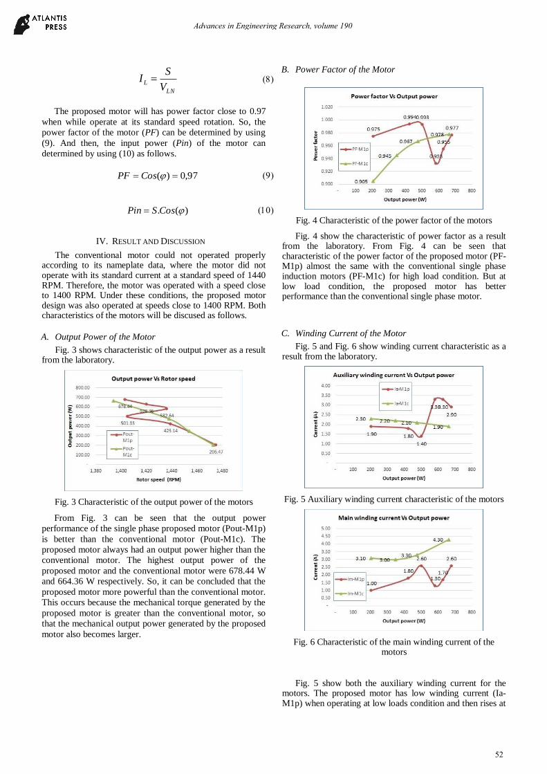
B. Power Factor of the Motor
Fig. 4 Characteristic of the power factor of the motors
Fig. 4 show the characteristic of power factor as a result from the laboratory. From Fig. 4 can be seen that characteristic of the power factor of the proposed motor (PF-M1p) almost the same with the conventional single phase induction motors (PF-M1c) for high load condition. But at low load condition, the proposed motor has better performance than the conventional single phase motor.
C. Winding Current of the Motor
Fig. 5 and Fig. 6 show winding current characteristic as a result from the laboratory.
Fig. 5 Auxiliary winding current characteristic of the motors
Fig. 6 Characteristic of the main winding current of the motors
Fig. 5 show both the auxiliary winding current for the motors. The proposed motor has low winding current (Ia-M1p) when operating at low loads condition and then rises at
Advances in Engineering Research, volume 190
52

high loads up to 2.9 A, but still below the nominal current 3.15 A. And when we see from Fig. 6, the main winding current of the proposed motor (Im-M1p) is always smaller than the single phase induction motor‟s (Im-M1c), so that the power losses on the proposed motor are smaller than conventional motor‟s. So that, this condition will make the proposed motor more powerful and efficient.
The results of the conclusion of the characteristics of both motors are shown in table 1.
TABLE I. CHARACTERISTIC CONCLUSION OF THE MOTORS
No.
Maximum Characteristic
Object Single phase
proposed motor
Conventional
single phase
induction motor
1. Output Power (W) 678.44 664.36
2. Power Factor 0.977 0.978
3. Auxiliary Winding
Current (A) 2.9 1.9
4. Main Winding
Current (A) 2.6 4.3
V. CONCLUSION
This study was a 4 windings design of a single phase induction motor with current control in the auxiliary winding. The proposed motor had 4 windings, three auxiliary windings and one main winding. The proposed motor can use lower capacitor capacitance to operate the motor, so the cost of the proposed motor is cheaper than conventional motors. When the auxiliary winding is controlled by a smart control system, the motor can be operated with better performance. Almost all proposed motor characteristics were better and more powerful than conventional single-phase comparator motor‟s.
ACKNOWLEDGMENT
Special thanks for all those involved who have helped us
in the research. We would also like to thank for „LLDIKTI
X‟ and 'KEMENRISTEKDIKTI INDONESIA‟ that had
supported this research funding with grant number
330/27.O10.5/PN/II/2019.
REFERENCES
[1] P. C. Sen, Principles of Electrical Machines and Power
Electronics, 2nd ed. New York: John Wiley & Sons, 1997.
[2] S. Sobhani, H. Yaghobi, and M. Samakoosh, “Optimize
efficiency and torque in the single-phase induction motor by
adjusting the design parameters,” 12th Int. Conf. Environ. Electr.
Eng. EEEIC 2013, pp. 237–241, 2013.
[3] F. Ahmed, E. Ghosh, and N. C. Kar, “Transient Thermal Analysis
of a Copper Rotor Induction Motor using a Lumped Parameter
Temperature Network Model,” IEEE, no. 1, 2016.
[4] M. Dems and K. Komeza, “Performance Characteristics of a
High-Speed Energy-Saving Induction Motor with an Amorphous
Stator Core,” IEEE Trans. Ind. Electron., vol. 61, no. 6, pp.
3046–3055, 2014.
[5] A. Krings, M. Cossale, A. Tenconi, J. Soulard, A. Cavagnino,
and A. Boglietti, “Characteristics comparison and selection guide
for magnetic materials used in electrical machines,” 2015 IEEE
Int. Electr. Mach. Drives Conf., pp. 1152–1157, 2015.
[6] W. Ding, L. Jiang, Y. Liao, J. Song, B. Li, and G. Wu, “Effect of
iron particle size and volume fraction on the magnetic properties
of Fe/silicate glass soft magnetic composites,” J. Magn. Magn.
Mater., vol. 378, pp. 232–238, 2015.
[7] N. A. Ahmed, “Three-phase induction motor operating from
single-phase supply with an electronically controlled capacitor,”
Electr. Power Syst. Res., vol. 73, no. 2, pp. 121–128, 2005.
[8] Y. A. Al-turki and H. Al-umari, “Application of the reference
frame theory to the dynamic analysis of a three-phase induction
motor fed from a single-phase supply,” Elsevier, vol. 53, pp.
149–156, 2000.
[9] Z. Anthony, “Equivalent Circuits for the M31D-ZA Motor ‟ s
Method ( Case Studies : Currents and Power Factor of the motor
),” IJETT, vol. 25, no. 1, pp. 49–52, 2015.
[10] Z. Anthony, “A Simple Method for Operating the Delta
Connection Standard of the 3-phase Induction Motor on Single
Phase Supply,” IJETT, vol. 15, no. 9, pp. 444–447, 2014.
[11] Z. Anthony, “A Simple Method For Operating The Three-Phase
Induction Motor On Single Phase Supply ( For Wye Connection
Standard ),” IJETT, vol. 5, no. 1, pp. 13–16, 2013.
[12] Z. Anthony, “Analyzing Characteristics of the Sheda ‟ s Method
for Operating the 3-phase induction Motor on Single Phase
Supply ( Case studies : output power and efficiency of the motor
),” IJETT, vol. 33, no. 4, pp. 175–179, 2016.
[13] Z. Anthony and E. Erhaneli, “A New Windings Design of 24 Slot
Capacitor-Start Capacitor-Run Induction Motor,” Int. J. Electr.
Comput. Eng., vol. 8, no. 5, pp. 3463–3470, 2018.
[14] Z. Anthony, E. Erhaneli, and Z. Zulkarnaini, “Windings Design
for Single-phase Induction Motors Base on 4- phase Induction
Motor ( Case study : identical windings design ),” in ICTIS 2018,
2018, vol. 01023, pp. 1–4.
Advances in Engineering Research, volume 190
53