single-cycle architecture - dmcs pages for students
TRANSCRIPT

Com
pute
r Arc
hite
ctur
e, IF
E CS
and
T&
CS, 4
thse
m
Single-Cycle Architecture

Com
pute
r Arc
hite
ctur
e, IF
E CS
and
T&
CS, 4
thse
mData flow
Data flow is synchronized with clock (edge) in sequential systems
Com
pute
r Arc
hite
ctur
e, IF
E CS
and
T&
CS, 4
thse
mArchitecture Elements - assumptions
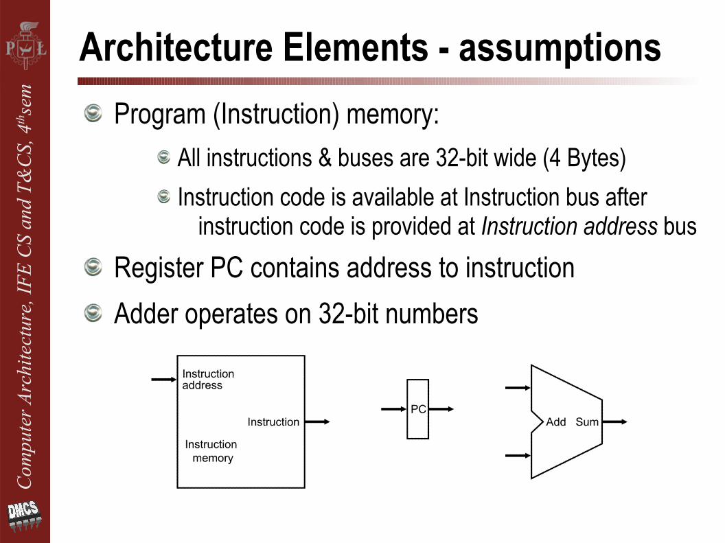
Program (Instruction) memory:All instructions & buses are 32-bit wide (4 Bytes)Instruction code is available at Instruction bus after
instruction code is provided at Instruction address busRegister PC contains address to instructionAdder operates on 32-bit numbers

Com
pute
r Arc
hite
ctur
e, IF
E CS
and
T&
CS, 4
thse
mInstruction Fetch Block
Instruction Fetch operationPC-write operation is triggered with clock signalPC is incremented by 4 in every clock cycleA sequence of instructions is fetched from memory

Com
pute
r Arc
hite
ctur
e, IF
E CS
and
T&
CS, 4
thse
mRegister-type Instructions (R-type)
R-type instructions perform operation only on (contents of) internal registers of processor
two source operands (Rrs i Rrt) are in internal registers
results is written to the internal register (Rrd)
R-type instruction code is composed of:unique number of instruction type (opcode)numbers of 3 registers (2x source and 1 result): rs, rt, rd
type of arithmetical or logical operation (func)
opcode rs rt rd ... func

Com
pute
r Arc
hite
ctur
e, IF
E CS
and
T&
CS, 4
thse
mRegister Direct Addressing
Rrs
Rrt
operand 1
operand 2
(Adresowanie bezpośrednie rejestrowe)
Operands are in internal registers
assembler:
ADD R1,R2,R7SUB R3,R6,R1OR R7,R3,R2AND R0,R2,R5
Rrd
operand 3

Com
pute
r Arc
hite
ctur
e, IF
E CS
and
T&
CS, 4
thse
mRegister File - assumptions
Contains 32 registers, each 32-bit wideAt register file output provides contents of two registers
addressed by ReadRegister1&2 input numbersRegister numbers are 5-bit wide (25 = 32)Writing to a selected internal register requires: the
register number (WriteRegister), data to be written (WriteData) and operation enable signal (RegWrite)
Write operation is synchronizedwith the clock signal

Com
pute
r Arc
hite
ctur
e, IF
E CS
and
T&
CS, 4
thse
mRegister File – Logical Concept
R0
clk
R1 R31
RegWrite
WriteData
WriteRegister
ReadReg.2
ReadReg.1

Com
pute
r Arc
hite
ctur
e, IF
E CS
and
T&
CS, 4
thse
mALU - assumptions
32-bit input & outputs (32-bit ALU)Operations: add, subtract, logical: AND, OR3-bit ALU-control busOnly one output control signal: Zero (Z)

Com
pute
r Arc
hite
ctur
e, IF
E CS
and
T&
CS, 4
thse
mR-type Instruction Execution
Source operands from Register File (Rrs i Rrt) are selected by register numbers from instruction codeALU result is written back to the register selected by Rrd at the end of clock signal cycle
opcode rs rt rd ... func31 26 | 25 21 | 20 16 | 15 11 | | 5 0
instruction fieldsbit numbers

Com
pute
r Arc
hite
ctur
e, IF
E CS
and
T&
CS, 4
thse
mData Memory - assumptions
Contains data of the program, organized in 32-bit words (4B)Data is present at ReadData bus after the address is provided at
Address bus and operation enable signal is active (MemRead)Memory modification requires the data and address to be present
at WriteData and Address buses and operation enable signal active (MemWrite)
Write operation is synchronizedwith the clock signal

Com
pute
r Arc
hite
ctur
e, IF
E CS
and
T&
CS, 4
thse
mSign Extension Unit - assumptions
Performs conversion of 16-bit binary numbers to 32-bit representation with proper sign handling (2C)Combinatorial logic, no clock signal required

Com
pute
r Arc
hite
ctur
e, IF
E CS
and
T&
CS, 4
thse
mTransfer Instructions (Load/Store)
Instructions perform data transfer:from data memory to internal register (Load)from internal register to data memory (Store)transfer info: internal register (Rrs) & memory address (Rrt)
constant value (offset) extends addressing rangeLoad/Store instruction code is composed of:
unique number of instruction type (opcode)numbers of two internal registers: rs, rt
constant (offset), added to the memory (base) address
opcode rs rt offset

Com
pute
r Arc
hite
ctur
e, IF
E CS
and
T&
CS, 4
thse
mRegister Indirect Addressing
data
Rrt
Rrs
data
address
+ offset
operand address
mem
ory addresses
0
n
with Offset (Adresowanie pośrednie rejestrowe z przesunięciem)
Offset is a signed number in 2's complementSTORE:
assembler: (SW – Store Word)
SW R7,(R5)SW R1,0x200(R2)
4B words

Com
pute
r Arc
hite
ctur
e, IF
E CS
and
T&
CS, 4
thse
mRegister Indirect Addressing
data
Rrt
Rrs
data
address
+ offset
operand address
mem
ory addresses
0
n
with Offset (Adresowanie pośrednie rejestrowe z przesunięciem)
Offset is a signed number in 2's complementLOAD:
assembler: (LW – Load Word)
LW R7,(R5)LW R1,0x200(R2)

Com
pute
r Arc
hite
ctur
e, IF
E CS
and
T&
CS, 4
thse
mLoad/Store Execution
Register Rrs + offset points to memory data (Load/Store)
Store: Contents of register Rrt (memory input) to be written (signal MemWrite active)
Load: memory output to be written to register Rrt
(signals MemRead and RegWrite active)

Com
pute
r Arc
hite
ctur
e, IF
E CS
and
T&
CS, 4
thse
mJump/Branch Instructions
Jump/Branch: interruption in execution of a sequence of consecutive instructions in memoryEvery Jump/Branch is a modification of the PC registerAbsolute (jumps) vs Relative (branches)
absolute – arbitrary new content loaded into PCrelative – offset added to the current value of PC
Unconditional vs Conditionalunconditional – jump is always performedconditional – final modification of PC depends on conditions
usually provided by ALU (bits C,V,Z,N)

Com
pute
r Arc
hite
ctur
e, IF
E CS
and
T&
CS, 4
thse
mRelative Conditional Branch (BEQ)
BEQ Rx,Ry,offset (Branch if Equal)– branch to address PC+offset*4 if Rx=Ry (Z=1)Instructions are 4B long, so branch range can be widened by pointing to every fourth byte (offset*4)BEQ instruction code is composed of:
unique number of instruction type (opcode)numbers of two internal registers: rs, rt
constant (offset), added to the memory (base) addressBEQ base address refers to instruction memory
opcode rs rt offset

Com
pute
r Arc
hite
ctur
e, IF
E CS
and
T&
CS, 4
thse
mRelative Conditional Branch (BEQ)
assembler: (BEQ)
BEQ R1,R2,0x40BEQ R0,R7,0xFF

Com
pute
r Arc
hite
ctur
e, IF
E CS
and
T&
CS, 4
thse
mR-type and Load/Store Together
Bus multiplexers:ALUSrc: selects the second ALU operandMemtoReg: selects the data to be written to a register

Com
pute
r Arc
hite
ctur
e, IF
E CS
and
T&
CS, 4
thse
mFetch Unit + R-type, Load/Store

Com
pute
r Arc
hite
ctur
e, IF
E CS
and
T&
CS, 4
thse
mFetch + R-type, Load/Store and Branch
Multiplexer: PCSrcselects the source for new PC value:
PC+4 or PC+offset*4

Com
pute
r Arc
hite
ctur
e, IF
E CS
and
T&
CS, 4
thse
mWrite to Register - correction
Multiplexer: RegDstselects the correct register number to be modified:
(R-type → rd, Load → rt)

Com
pute
r Arc
hite
ctur
e, IF
E CS
and
T&
CS, 4
thse
mControl Block
Control: combinatorial logic generating all control signal
Com
pute
r Arc
hite
ctur
e, IF
E CS
and
T&
CS, 4
thse
mAbsolute Unconditional Jump (JMP)
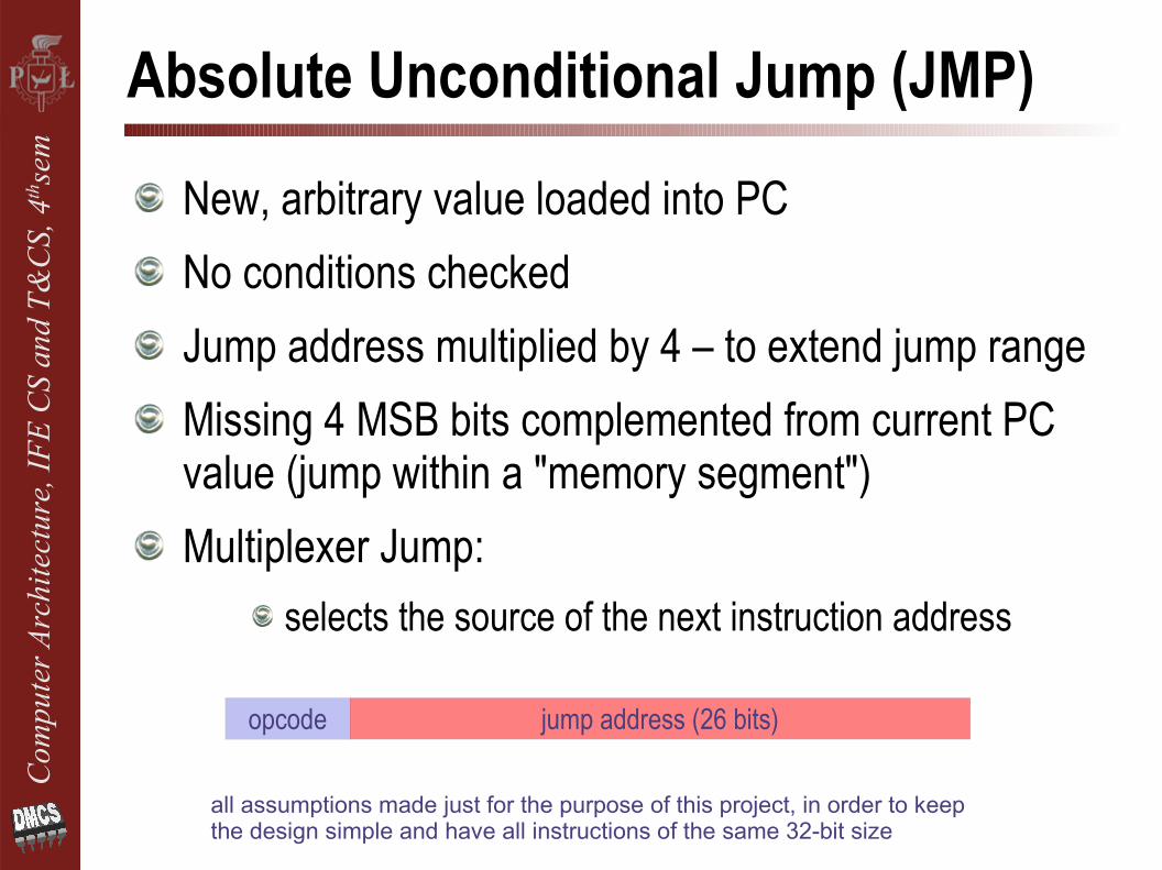
New, arbitrary value loaded into PCNo conditions checkedJump address multiplied by 4 – to extend jump rangeMissing 4 MSB bits complemented from current PC value (jump within a "memory segment")Multiplexer Jump:
selects the source of the next instruction address
opcode jump address (26 bits)
all assumptions made just for the purpose of this project, in order to keep the design simple and have all instructions of the same 32-bit size

Com
pute
r Arc
hite
ctur
e, IF
E CS
and
T&
CS, 4
thse
mComplete Single-Cycle Architecture

Com
pute
r Arc
hite
ctur
e, IF
E CS
and
T&
CS, 4
thse
mImplemented Instruction Set
Register (R-type)
Load
Store
BEQ
JMPopcode jump address (26 bits)
opcode rs rt offset
opcode rs rt rd ... func
opcode rs rt offset
opcode rs rt offset

Com
pute
r Arc
hite
ctur
e, IF
E CS
and
T&
CS, 4
thse
mALU Control
All R-type instructions have identical opcode field, but differ in Func field (type of operation for ALU)Main control block receives only instruction opcode and generates signal ALUop (the same for all R-types)ALU Control Unit takes into accountFunc field (only for R-types) and provides directcontrol for ALUALUop signal indicatesinstruction family, but notthe actual operation

Com
pute
r Arc
hite
ctur
e, IF
E CS
and
T&
CS, 4
thse
mALU Control
AND 000OR 001
ADD 010SUB 110
Func ALU operation(Neg.+Oper)

Com
pute
r Arc
hite
ctur
e, IF
E CS
and
T&
CS, 4
thse
mALU Control – Summary
ALU Control is a combinatorial logic – operation can be described by truth table