“single chip cloud computer” - ucsb computer … howard advanced microprocessor research intel...
TRANSCRIPT
Jim HeldIntel Fellow & Director
Tera-scale Computing Research
“Single-chip Cloud Computer”An experimental many-core processor from Intel Labs
Intel Labs Single-chip Cloud Computer Symposium February 12, 2010

Agenda
10:00 Welcome and Opening Remarks
10:15 SCC Hardware Architecture Overview
11:15 Today’s SCC Software Environment
12:15 Buffet Lunch – Informal discussions
13:15 Message Passing on the SCC
13:45 Software-Managed Coherency
14:15 Application ”Deep Dive”: Javascript Farm on SCC
14:45 Break
15:00 Plans for future SCC access
15:30 Q&A
16:30 Adjourn
2

Motivations for SCC
•Many-core processor research
–High-performance power-efficient fabric
–Fine-grain power management
–Message-based programming support
•Parallel Programming research
–Better support for scale-out model servers> Operating system, communication architecture
–Scale-out programming model for client> Programming languages, runtimes
3

Agenda
10:00 Welcome and Opening Remarks
10:15 SCC Hardware Architecture Overview
11:15 Today’s SCC Software Environment
12:15 Buffet Lunch – Informal discussions
13:15 Message Passing on the SCC
13:45 Software-Managed Coherency
14:15 Application ”Deep Dive”: Javascript Farm on SCC
14:45 Break
15:00 Plans for future SCC access
15:30 Q&A
16:30 Adjourn
4

Jason HowardAdvanced Microprocessor Research
Intel Labs
SCC Architecture and Design Overview
Intel Labs Single-chip Cloud Computer Symposium February 12, 2010
Agenda
• Feature set
• Architecture overview
– Core
– Interconnect Fabric
– Memory model & Message passing
– I/O and System Overview
• Design Overview
– Tiled design methodology
– Clocking
– Power management
• Results
• Summary
6
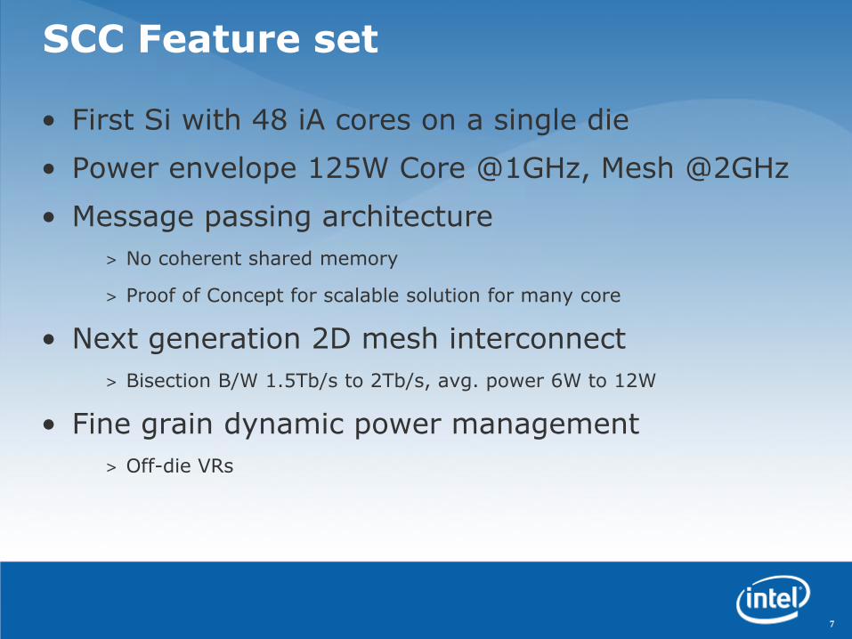
SCC Feature set
• First Si with 48 iA cores on a single die
• Power envelope 125W Core @1GHz, Mesh @2GHz
• Message passing architecture
> No coherent shared memory
> Proof of Concept for scalable solution for many core
• Next generation 2D mesh interconnect
> Bisection B/W 1.5Tb/s to 2Tb/s, avg. power 6W to 12W
• Fine grain dynamic power management
> Off-die VRs
7

MC
0M
C1
MC
2M
C3
System InterfaceVRC
Router
IA-32 Core0
L2$0
256KB
L2$1
256KB
IA-32 Core1
MPB16KB
Router Tile
Die Architecture
2 core clusters in 6x4 2-D mesh
16B
8

Core Memory Management
• Core cache coherency is restricted to private memory space
– Maintaining cache coherency for shared memory space is under software control
• Each core has an address Look Up Table (LUT) extension
– Provides address translation and routing information
• LUT must fit within the core and memory controller constraints
• LUT boundaries are dynamically programmed
Shared
Boot
1GBPrivate
Maps to MC0
Maps to VRC
Maps to MPBs
Maps to MC0
CORE0 LUT Example
0
1
254
255
… …
9

On-Die 2D Mesh
• 16B wide data links + 2B sideband
> Target frequency: 2GHz
> Bisection bandwidth: 2 Tb/s
> Latency: 4 cycles (2ns)
• 2 message classes and 8 VCs
• Low power circuit techniques
> Sleep, clock gating, voltage control, low power RF
> Low power 5 port crossbar design
• Speculative VC allocation
• Route pre-computation
• Single cycle switch allocation
10

Input
Arbitration Switch
Arbitration
FIF
O Route
Pre-compute
VC
Allocation
Cycle 1 Cycle 2 Cycle 3 Cycle 4In-Port 0
Frequency 2GHz @ 1.1V
Latency 4 cycles
Link Width 16 Bytes
Bandwidth 64GB/s per link
Architecture 8 VCs over 2 MCs
Power Consumption 500mW @ 50°C
16B
16B
Router Architecture
11

Message Passing on SCC
•Message passing is done through shared memory space
•Two classes of shared memory:
–Off-die, DRAM: Uncachable shared memory … results in high latency message passing
–On-die, message passing buffers (MPB) … low latency message passing> On-die dedicated message buffers placed in each tile to
improve message passing performance
> Message bandwidth improved to 1 GB/s
12
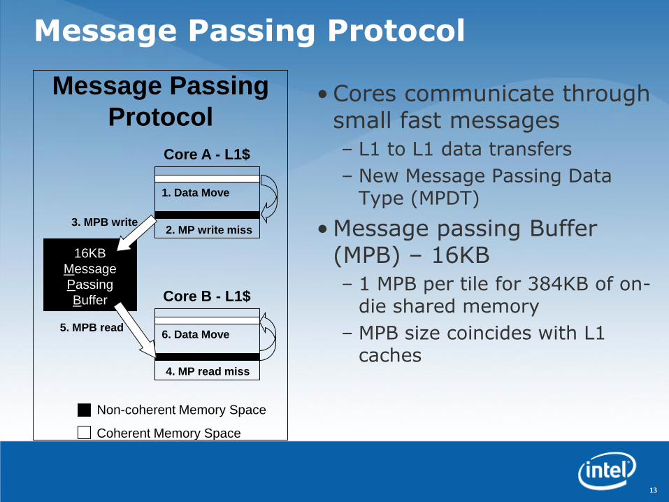
Non-coherent Memory Space
Coherent Memory Space
Message Passing
Protocol
16KB
Message
Passing
Buffer
1. Data Move
Core A - L1$
2. MP write miss
6. Data Move
Core B - L1$
4. MP read miss
3. MPB write
5. MPB read
Message Passing Protocol
• Cores communicate through small fast messages
– L1 to L1 data transfers
– New Message Passing Data Type (MPDT)
• Message passing Buffer (MPB) – 16KB
– 1 MPB per tile for 384KB of on-die shared memory
– MPB size coincides with L1 caches
13

Dedicated Message Buffers
• Cache line transfers into L1 cache of receiving core implemented through on-die message passing buffers
• Each tile has 16KB MPB
• Part of the shared memory space is statically mapped into MPB in each tile rather than into memory controller
• Messages larger than MPB can still go out to main memory
Mesh
Send Core
:Data
:Req/ResMeshIF
Msg Buf
ReceiveCore
MeshIF
Msg Buf
Mesh
Send Core
:Data
:Req/ResMeshIF
Msg Buf
ReceiveCore
MeshIF
Msg Buf
Local write, remote read Remote write, local read
14

System Interface
• JTAG access to config system while in reset/debug> Done on Power Reset from Management Console PC
> Configuring memory controller etc.
> Reset cores with default configuration
• Management Console PC can use Mem-mapped registers to modify default behavior
> Configuration and voltage control registers
> Message passing buffers
> Memory mapping
• Preload image and reset rather than PC bootstrap> BIOS & firmware a work in progress
15
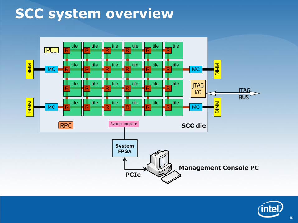
SCC system overview
16
tile tile
tile tile
tile tile
tile tile
tile tile
MC
MC
MC
MC
DIM
M
DIM
MD
IMM
DIM
M
System Interface
R
R
R
R
R
R
R
R
tile tile tile tile
tile tile
tile tile
tile tile
tile tile
tile tile
R
R
R
R
R
R
R
R
R
R
R
R
R
R
R
R
System FPGA
PCIeManagement Console PC
SCC die
JTAGI/O JTAG
BUS
PLL
RPC

SCC full chip
Technology 45nm Process
Interconnect 1 Poly, 9 Metal (Cu)
Transistors Die: 1.3B, Tile: 48M
Tile Area 18.7mm2
Die Area 567.1mm2
17
13
21.4mm
26.5mm
DDR3MC
DDR3MC
PLL + I/O
RPC
DDR3MC
DDR3MC
JTAG
System Interface + I/O
SCC TILE
SCCTILE

P54cL2$ + CC
GCUMIU MPB
CCF
Router
P54c
P54cL2$ + CC
GCUMIU MPB
L2$ + CC
CC
F• 2 P54C cores (16K L1$/core)
• 256K L2$ per core
• 8K Message passing buffer
• Clock Crossing FIFOs b/w Mesh
interface unit and Router
• Tile area 18.7mm2
• Core are 3.9mm2
• Cores and uncore units @1GHz
• Router @2GHz
SCC Dual-core Tile
18

SIF
MC
0
MC
2
MC
1
MC
3
Router Tile
Clock Gating
VRC
PLL
Port_En
Router_En L2$1_En
L2$0_En
Tile_EN
Core1_En
Core1_En
Port
CLKs
L2$1 clk
L2$0 clk
Core0
clk
Core1
clk
[4:0]
Clock Distribution
• Balanced H-tree clock distribution
• Designed to provide 4GHz clock to tile entry points
• Simulated skew for adjacent tiles – 5ps
• Cross die skew irrelevant
19

27 Frequency Islands (FI) 8 Voltage Islands (VI)
Voltage and Frequency islands
20

SCC Clock Crossing FIFO (CCF)
• 6 entry deep FIFO, 144-bits wide
• Built-in Voltage translation: M, N ratios and pointer separation scanned in
• Key Benefit: independent mesh & tile frequency
Vcc1, F1 Vcc2, F2
21
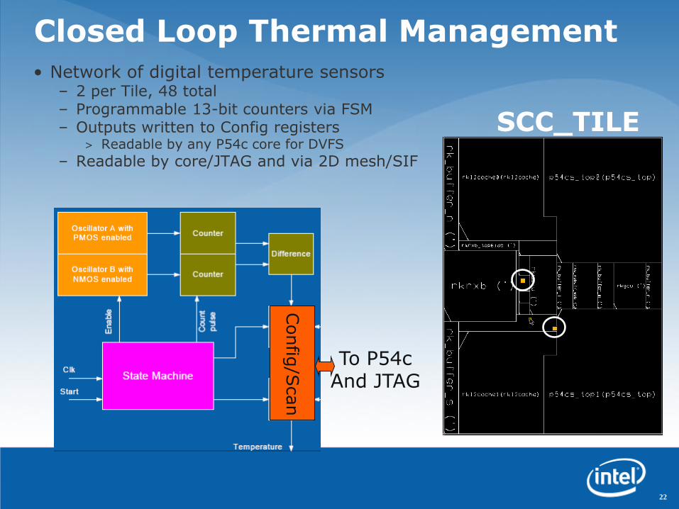
Closed Loop Thermal Management• Network of digital temperature sensors
– 2 per Tile, 48 total– Programmable 13-bit counters via FSM– Outputs written to Config registers
> Readable by any P54c core for DVFS
– Readable by core/JTAG and via 2D mesh/SIF
22
Config
/Scan
To P54cAnd JTAG
SCC_TILE

Package and Test Board
Technology 45nm Process
Package 1567 pin LGA package
14 layers (5-4-5)
Signals 970 pins
23

Core & Router Fmax
24

Measured full chip power
25

Power breakdown
Full Power Breakdown
Total -125.3WCores
69%MC &
DDR3-
800
19%
Routers
& 2D-
mesh
10%
Global
Clocking
2%
Low Power Breakdown
Total - 24.7W
Cores
21%
MC &
DDR3-
800
69%
Routers
& 2D-
mesh
5%
Global
Clocking
5%
Clocking: 1.9W Routers: 12.1W
Cores: 87.7W MCs: 23.6W
Clocking: 1.2W Routers: 1.2W
Cores: 5.1W MCs: 17.2W
Cores-125MHz, Mesh-250MHz, 0.7V, 50°CCores-1GHz, Mesh-2GHz, 1.14V, 50°C
26

Summary
• A 48 IA-32 core processor in 45nm CMOS • Second generation 2D-mesh network• 4 DDR3 channels in a 6×4 • Highest level of IA-32 integration
• New message passing HW for increased performance• 384KB of on-die shared memory• Message passing memory type
• Power management employs 8VIs and 28FIs for DVFS
• Chip dissipates between 25W and 125W as performance scales• 25W at 0.7, 125MHz core, 250MHz mesh and 50°C• 125W at 1.14V, 1GHz core, 2GHz mesh and 50°C
27

Agenda
10:00 Welcome and Opening Remarks
10:15 SCC Hardware Architecture Overview
11:15 Today’s SCC Software Environment
12:15 Buffet Lunch – Informal discussions
13:15 Message Passing on the SCC
13:45 Software-Managed Coherency
14:15 Application ”Deep Dive”: Javascript Farm on SCC
14:45 Break
15:00 Plans for future SCC access
15:30 Q&A
16:30 Adjourn
28

Michael Riepen, Michael Konow Germany Research Center
sccKit Software framework
for SCC Platform
Intel Labs Single-chip Cloud Computer Symposium February 12, 2010
Content
• Platform
– Platform overview
– System Interface FPGA bitstream
– Board management controller (BMC) firmware
• SCC Software
– Customized Linux
– bareMetalC
• Management Console PC Software
– PCIe driver with integrated TCP/IP driver
– Programming API for communication with SCC platform
– GUI for interaction with SCC platform
– Command line tools for interaction with SCC platform
30

Content
• Platform
– Platform overview
– System Interface FPGA bitstream
– Board management controller (BMC) firmware
• SCC Software
– Customized Linux
– bareMetalC
• Management Console PC Software
– PCIe driver with integrated TCP/IP driver
– Programming API for communication with SCC platform
– GUI for interaction with SCC platform
– Command line tools for interaction with SCC platform
31

SCC Platform Board Overview
32

SCC “Chipset”
•System Interface FPGA
–Connects to SCC Mesh interconnect
– IO capabilities like PCIe, Ethernet & SATA
–Bitstream is part of sccKit distribution
•Board Management Controller (BMC)
– JTAG interface for Clocking, Power etc.
–USB Stick with FPGA bitstream
–Network interface for User intercation via Telnet
–Status monitoring
–Firmware is part of sccKit distribution
33

Content
• Platform
– Platform overview
– System Interface FPGA bitstream
– Board management controller (BMC) firmware
• SCC Software
– Customized Linux
– bareMetalC
• Management Console PC Software
– PCIe driver with integrated TCP/IP driver
– Programming API for communication with SCC platform
– GUI for interaction with SCC platform
– Command line tools for interaction with SCC platform

SCC Linux Build
The sccKit comes with a custom Linux build whichcan be used to execute own applications:
• Kernel 2.6.16 with Busybox 1.15.1
• Booting w/o BIOS possible (Kernel mods)
• Dropbear ssh
• On-die TCP/IP network drivers
• Off-die TCP/IP driver for connection to management console including NFS service.
• Drivers for low level access to SCC specific hardware (e.g. MPB).
35
SCC Linux Apps
•Cross-compilers for Pentium processor compatible IA cores available (C++, Fortran)
•Write own low level device drivers for deeper dives.
•Cross compiled MPI2 including iTAC trace analyzer available.
36

Creating own SCC binaries
• It is also possible to write software that directly executes on SCC cores such as an operating system.
• C++ based programming framework “bareMetalC”is available and allows direct access to all dedicated SCC hardware features (e.g. MPB).
Up sides Down sides
Direct access to low level features of SCC.
Limited IO capabilities.
No overhead from OS. Harder to debug.
Full flexibility. Low level coding w/o OS
37

bareMetalC Apps
•bareMetalC used for bring-up and production tests (e.g. BIST test)
•Useful for creation of own low level apps (e.g. customized OS)
•SCC communication environment (RCCE) with MPI-like API available including several applications
38

Content
• Platform
– Platform overview
– System Interface FPGA bitstream
– Board management controller (BMC) firmware
• SCC Software
– Customized Linux
– bareMetalC
• Management Console PC Software
– PCIe driver with integrated TCP/IP driver
– Programming API for communication with SCC platform
– GUI for interaction with SCC platform
– Command line tools for interaction with SCC platform

PCIe driver with Ethernet
•Management Console PC comes with PCIe driver that provides:
–TCP/IP connection to SCC
–Connection to Management Console PC applications.
–Access to all memory and register locations of SCC.
40

Creating Management Console PC Apps
• Written in C++ making use of Nokia Qt cross-platform application and UI framework.
• Low level API (sccApi) with access to SCC and board management controller via PCIe.
• Code of sccGui as well as command line tools is available as code example. These tools use and extend the low level API.
41

sccGui
• Read and write system memory andregisters.
• Boot OS or otherworkloads (e.g. bareMetalC).
• Open SSH connections to booted Linux cores
• Performance meter
• Initialize Platform via Board Management Controller.
42

sccGui for debugging
Modify registers
Read system memory
43
sccBoot & sccReset
•sccBoot:A command-line tool that allows to boot Linux on selected cores and to check the status (“which cores are currently booted”).
•sccReset:A command-line tool that allows to reset selected SCC cores.
44

sccKonsole
• Regular konsole, with automatic login to selected cores.
• Enables broadcasting amongst shells.
45

Future
•Linux will be the default OS for self-contained booting
•Self-boot firmware is in preparation
Let„s shape the future together!
46

Agenda
10:00 Welcome and Opening Remarks
10:15 SCC Hardware Architecture Overview
11:15 Today’s SCC Software Environment
12:15 Buffet Lunch – Informal discussions
13:15 Message Passing on the SCC
13:45 Software-Managed Coherency
14:15 Application ”Deep Dive”: Javascript Farm on SCC
14:45 Break
15:00 Plans for future SCC access
15:30 Q&A
16:30 Adjourn
47

Agenda
10:00 Welcome and Opening Remarks
10:15 SCC Hardware Architecture Overview
11:15 Today’s SCC Software Environment
12:15 Buffet Lunch – Informal discussions
13:15 Message Passing on the SCC
13:45 Software-Managed Coherency
14:15 Application ”Deep Dive”: Javascript Farm on SCC
14:45 Break
15:00 Plans for future SCC access
15:30 Q&A
16:30 Adjourn
48

Richly
Restricted
Communicating Cores
Capability Communication Environment
Ecosystem
Radically Cool Coordination E-science
Research Cores Communication Environment
Rabble-of Communicating Cores Experiments
Rock Creek Communication Environment
Rorschach Core Communication Express
Rapidly Communicating Cores Env.
R C C EA small library for many-core
communication
Reduced Compact Communication Environment
Rob van der Wijngaart Software and Services Group
Tim Mattson Intel Labs
Intel Labs Single-chip Cloud Computer Symposium
February 12, 2010

Agenda
•Views of SCC: HW, SW and Platforms
•RCCE: A communication environment for application programmers.
•Benchmarks and Results
•Power management
50

Top Level Hardware Architecture
•6x4 mesh 2 Pentium™ P54c cores per tile
•256KB L2 Cache, 16KB shared MPB per tile
•4 iMCs, 16-64 GB total memory
Mem
ory
Co
ntr
oll
er
Tile
R
Tile
R
Tile
R
Tile
R
Tile
R
Tile
R
Tile
R
Tile
R
Tile
R
Tile
R
Tile
R
Tile
R
Tile
R
Tile
R
Tile
R
Tile
R
Tile
R
Tile
R
Tile
R
Tile
R
Tile
R
Tile
R
Tile
R
Tile
R
Mem
ory
Co
ntr
oll
er
Mem
ory
Co
ntr
oll
erM
emo
ry C
on
tro
ller
System I/F
Tile
Core 1
Core 0
L2$1
L2$0
Router MPB
Core 1
Core 0
R = router, iMC = integrated Memory Controller, MPB = message passing buffer
Tile area: ~17 mm2
SCC die area: ~567 mm2
51

Programmer’s view of SCC• 48 x86 cores with the familiar x86 memory model for Private
DRAM• 3 memory spaces, with fast message passing between cores
( / means on/off-chip)
CPU_0
L1
$
L2
$
Private DRAM
CPU_47
L1
$
L2
$
Private DRAM
…
Shared on-chip Message Passing Buffer (8KB/core)
Shared off-chip DRAM (variable size)
t&s t&s
t&s Shared test and set register
52

SCC Software research goals
• Understand programmability and application scalability of many-core chips.
• Answer question “what can you do with a many-core chip that has (some) shared non-cache-coherent memory?”
• Study usage models and techniques for software controlled power management
• Sample software for other programming model and applications researchers (industry partners, Flame group at UT Austin, UPCRC, YOU …)
Our research resulted in a light weight, compact, low latency
communication library called RCCE (pronounced “Rocky”)
Third party names are the property of their owners.53

SCC Platforms
• Three platforms for SCC and RCCE
– Functional emulator (on top of OpenMP)
– SCC board with two “OS Flavors” … Linux or Baremetal (i.e. no OS)
Rock creek
Apps
Linux
RCCE
PC or server with
Windows or Linux
Apps
OpenMP
Rock creek
Apps
Baremetal C
RCCE_EMU
Driver
RCCE RCCE
Functional emulator, based on OpenMP. SCC board – NO OpenMP
iccifortMKL
icc MKL icc fort MKL
RCCE supports greatest common denominator between the three platforms
Third party names are the property of their owners.54

Agenda
•Views of SCC: HW, SW and Platforms
•RCCE: A communication environment for application programmers.
•Benchmarks and Results
•Power management
55

High level view of RCCE
• RCCE is a compact, lightweight communication environment.
– SCC and RCCE were designed together side by side:> … a true HW/SW co-design project.
• RCCE is a research vehicle to understand how message passing APIs map onto many core chips.
• RCCE is for experienced parallel programmers willing to work close to the hardware.
• RCCE Execution Model:
– Static SPMD: > identical UEs created together when a program starts (this is a
standard approach familiar to message passing programmers)
UE: Unit of Execution … a software entity that advances a program
counter (e.g. process of thread).
56

How does RCCE work? Part 1
Consequences of MPBT properties:
If data changed by another core and image still in L1, read returns stale data.
Solution: Invalidate before read.
L1 has write-combining buffer; write incomplete line? expect trouble!
Solution: don’t. Always push whole cache lines
If image of line to be written already in L1, write will not go to memory.
Solution: invalidate before write.
Message passing buffer
memory is special … of
type MPBT
Cached in L1, L2
bypassed. Not coherent
between cores
Data cached on read, not
write. Single cycle op to
invalidate all MPBT in L1
… Note this is not a flush
Discourage user operations on data in MPB. Use only as a data movement
area managed by RCCE … Invalidate early, invalidate often57

How does RCCE work? Part 2
…0 1 2 473
• Treat Msg Pass Buf (MPB) as 48 smaller buffers … one per core.
58

How does RCCE work? Part 2
…0 1 2 473
• Treat Msg Pass Buf (MPB) as 48 smaller buffers … one per core.
2
A = (double *) RCCE_malloc(size)
Called on all cores so any core can
put/get(A at Core_ID) without error-
prone explicit offsets
Flags allocated and
used to coordinate
memory ops
59
• Symmetric name space … Allocate memory as a collective op. Each core gets a variable with the given name at a fixed offset from the beginning of a core’s MPB.

How does RCCE work? Part 3• The foundation of RCCE is a one-sided put/get interface.
• Symmetric name space … Allocate memory as a collective op. Each core gets a variable with the given name at a fixed offset from the beginning of a core’s MPB.
0
CPU_0
L1
$
L2
$
Private DRAM
t&s
CPU_47
L1
$
L2
$
Private DRAM
t&s
47…
60

How does RCCE work? Part 3• The foundation of RCCE is a one-sided put/get interface.
• Symmetric name space … Allocate memory as a collective op. Each core gets a variable with the given name at a fixed offset from the beginning of a core’s MPB.
0
CPU_0
L1
$
L2
$
Private DRAM
t&s
CPU_47
L1
$
L2
$
Private DRAM
t&s
47…
Put(A,0)
61

How does RCCE work? Part 3• The foundation of RCCE is a one-sided put/get interface.
• Symmetric name space … Allocate memory as a collective op. Each core gets a variable with the given name at a fixed offset from the beginning of a core’s MPB.
0
CPU_0
L1
$
L2
$
Private DRAM
t&s
CPU_47
L1
$
L2
$
Private DRAM
t&s
47…
Put(A,0) Get(A, 0)
62

How does RCCE work? Part 3• The foundation of RCCE is a one-sided put/get interface.
• Symmetric name space … Allocate memory as a collective op. Each core gets a variable with the given name at a fixed offset from the beginning of a core’s MPB.
0
CPU_0
L1
$
L2
$
Private DRAM
t&s
CPU_47
L1
$
L2
$
Private DRAM
t&s
47…
Put(A,0) Get(A, 0)
… and use flags to make the puts and gets “safe”
63

The RCCE library
• RCCE API provides the basic message passing functionality expected in a tiny communication library:
– One + two sided interface (put/get + send/recv) with synchronization flags and MPB management exposed.
– The “gory” interface for programmers who need the most detailed control over SCC
– Two sided interface (send/recv) with most detail (flags and MPB management) hidden.
– The “basic” interface for typical application programmers.
64
put() get()
send() recv ()

Agenda
•Views of SCC: HW, SW and Platforms
•RCCE: A communication environment for application programmers.
•Benchmarks and Results
•Power management
65
Linpack and NAS Parallel benchmarks
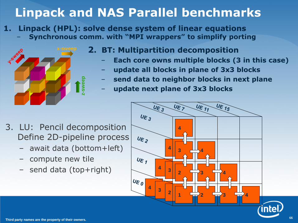
3. LU: Pencil decompositionDefine 2D-pipeline process
– await data (bottom+left)
– compute new tile
– send data (top+right)
4
4
4
4
4
4
4
3
33
3
3
22
2
1
x-sweep
z-s
we
ep
1. Linpack (HPL): solve dense system of linear equations– Synchronous comm. with “MPI wrappers” to simplify porting
2. BT: Multipartition decomposition
– Each core owns multiple blocks (3 in this case)
– update all blocks in plane of 3x3 blocks
– send data to neighbor blocks in next plane
– update next plane of 3x3 blocks
66Third party names are the property of their owners.

RCCE functional emulator vs. MPIHPL implementation of
the LINPACK benchmark
0
0.5
1
1.5
2
2.5
3
3.5
4
4.5
5
1 21 41 61 81 101 121 141 161 181 201
GF
lop
s
Case Number
MPI
RCCE
RCCE 1-bit flags
67
Standard HPL algorithm variant case numbers
GF
LO
PS
*3 GHz Intel® Xeon® MP processor in a 4 socket SMP platform (4 cores total), L2=1MB, L3=8MB, Intel® icc 10.1 compiler, Intel® MPI 2.0
Performance tests and ratings are measured using specific computer systems and/or components and reflect the approximate performance of Intel products as measured by those tests. Any difference in
system hardware or software design or configuration may affect actual performance. Buyers should consult other sources of information to evaluate the performance of systems or components they are
considering purchasing. For more information on performance tests and on the performance of Intel products, reference <http://www.intel.com/performance> or call (U.S.) 1-800-628-8686 or 1-916-356-3104.
These results provide a comparison of RCCE and MPI on an older 4 processor Intel® Xeon® MP
SMP platform* using a tiny 4x4 block size. These are not official MP-LINPACK results.
Matrix Order fixed at 2200
4 Intel®Xeon® MP Processors
Third party names are the property of their owners.

RCCE functional emulator vs. MPIHPL implementation of
the LINPACK benchmark
0
0.5
1
1.5
2
2.5
3
3.5
4
4.5
5
1 21 41 61 81 101 121 141 161 181 201
GF
lop
s
Case Number
MPI
RCCE
RCCE 1-bit flags
Low overhead synchronous
message passing pays off
even in emulator mode
(compared to MPI)
68
Standard HPL algorithm variant case numbers
GF
LO
PS
*3 GHz Intel® Xeon® MP processor in a 4 socket SMP platform (4 cores total), L2=1MB, L3=8MB, Intel® icc 10.1 compiler, Intel® MPI 2.0
Performance tests and ratings are measured using specific computer systems and/or components and reflect the approximate performance of Intel products as measured by those tests. Any difference in
system hardware or software design or configuration may affect actual performance. Buyers should consult other sources of information to evaluate the performance of systems or components they are
considering purchasing. For more information on performance tests and on the performance of Intel products, reference <http://www.intel.com/performance> or call (U.S.) 1-800-628-8686 or 1-916-356-3104.
These results provide a comparison of RCCE and MPI on an older 4 processor Intel® Xeon® MP
SMP platform* using a tiny 4x4 block size. These are not official MP-LINPACK results.
Matrix Order fixed at 2200
4 Intel®Xeon® MP Processors
Third party names are the property of their owners.

Linpack, on the Linux SCC platform
0
0.5
1
1.5
2
2.5
3
3.5
4
0 10 20 30 40 50
# cores
GF
lop
s
Matrix order 1000
• Linpack (HPL)* strong scaling results:– GFLOPS vs. # of cores for a fixed size problem (1000).– This is a tough test … scaling is easier for large problems.
• Calculation Details:– Un-optimized C-BLAS– Un-optimized block size (4x4)– Used latency-optimized whole
cache line flags– Performance dropped ~10% with
memory optimized 1-bit flags
69
SCC processor 500MHz core, 1GHz routers, 25MHz system interface, and DDR3 memory at 800 MHz.
Performance tests and ratings are measured using specific computer systems and/or components and reflect the approximate performance of Intel products as measured by those tests. Any difference in
system hardware or software design or configuration may affect actual performance. Buyers should consult other sources of information to evaluate the performance of systems or components they are
considering purchasing. For more information on performance tests and on the performance of Intel products, reference <http://www.intel.com/performance> or call (U.S.) 1-800-628-8686 or 1-916-356-3104.
* These are not official LINPACK benchmark results.
Third party names are the property of their owners.

LU/BT NAS Parallel Benchmarks, SCC
0
400
800
1200
1600
2000
0 10 20 30 40
# cores
MF
lop
s
LU
BT
• Using latency optimized, whole cache line flags
Problem size: Class A, 64 x 64 x 64 grid*
70
SCC processor 500MHz core, 1GHz routers, 25MHz system interface, and DDR3 memory at 800 MHz.
Performance tests and ratings are measured using specific computer systems and/or components and reflect the approximate performance of Intel products as measured by those tests. Any difference in
system hardware or software design or configuration may affect actual performance. Buyers should consult other sources of information to evaluate the performance of systems or components they are
considering purchasing. For more information on performance tests and on the performance of Intel products, reference <http://www.intel.com/performance> or call (U.S.) 1-800-628-8686 or 1-916-356-3104.
* These are not official NAS Parallel benchmark results.
Third party names are the property of their owners.
Agenda
•Views of SCC: HW, SW and Platforms
•RCCE: A communication environment for application programmers.
•Benchmarks and Results
•Power management
71

RCCE Power Management API
• RCCE power management emphasizes safe control: V/GHz changed together within each 4-tile (8-core) power domain.
– A Master core sets V + GHz for all cores in domain.
> RCCE_istep_power():
• steps up or down V + GHz, where GHz is max for selected voltage.
> RCCE_wait_power():
• returns when power change is done
> RCCE_step_frequency():
• steps up or down only GHz
• Power management latencies
– V changes: Very high latency, O(Million) cycles.
– GHz changes: Low latency, O(few) cycles.
72

Conclusions
• RCCE software works– RCCE‟s restrictions (Symmetric MPB memory model and blocking
communications) have not been a fundamental obstacle
– Functional emulator is a useful development/debug device
• SCC architecture– The on-chip MPB was effective for scalable message passing
applications
– Software controlled power management works … but it‟s challenging to use because (1) granularity of 8 cores and (2) high latencies for voltage changes
– The Test&set registers (only one per core) will be a bottleneck. > Sure wish we had asked for more!
• Future work– Add shmalloc() to expose shared off-chip DRAMM (in progress).
– Move resource management into OS/drivers so multiple apps can work together safely.
– We have only just begun to explore power management capabilities … we need to explore additional usage models.
73

SW Acknowledgements
Management Console software Michael Riepen
BareMetalC workflow Michael Riepen
Linux for SCC Thomas Lehnig
Paul Brett
System Interface FPGA development Matthias Steidl
TCP/IP network driver Werner Haas
RCCE library and apps Rob Van der Wijngaart Tim Mattson
Developer tools (Intel compilers and math libraries)
Patrick Kennedy
Mandelbrot app + viz Michael Riepen
• SCC System software:
• SCC Application software:
74
Agenda
10:00 Welcome and Opening Remarks
10:15 SCC Hardware Architecture Overview
11:15 Today’s SCC Software Environment
12:15 Buffet Lunch – Informal discussions
13:15 Message Passing on the SCC
13:45 Software-Managed Coherency
14:15 Application ”Deep Dive”: Javascript Farm on SCC
14:45 Break
15:00 Plans for future SCC access
15:30 Q&A
16:30 Adjourn
75

Sai Luo, Xiaocheng Zhou, Tiger Hu Chen, Shoumeng Yan, Ying Gao
Intel Labs China
Wei Liu, Brian Lewis, Bratin SahaProgramming Systems Lab
Software Managed Coherency on SCC
Intel Labs Single-chip Cloud Computer Symposium February 12, 2010
Revive an old topic: cache coherence ?• Software-managed coherence was a popular topic
– Been around at least a couple of decades
– Mostly targeting multiprocessors or clusters of workstations
77

Revive an old topic: cache coherence ?• Software-managed coherence was a popular topic
– Been around at least a couple of decades
– Mostly targeting multiprocessors or clusters of workstations
• World is changing
– Many cores on a single die
– Much higher bandwidth and lower latency
– Running out of power budget
78

Revive an old topic: cache coherence ?• Software-managed coherence was a popular topic
– Been around at least a couple of decades
– Mostly targeting multiprocessors or clusters of workstations
• World is changing
– Many cores on a single die
– Much higher bandwidth and lower latency
– Running out of power budget
• World is not changing
– Legacy code written in shared memory programming model
– Coherent memory requirement from ISVs
79
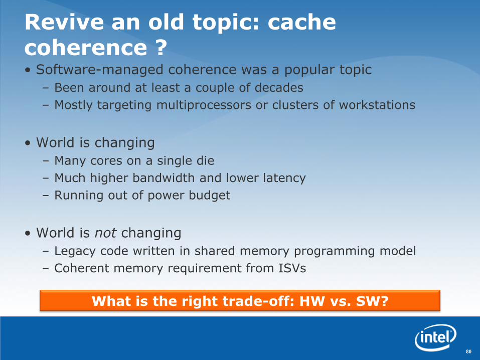
Revive an old topic: cache coherence ?• Software-managed coherence was a popular topic
– Been around at least a couple of decades
– Mostly targeting multiprocessors or clusters of workstations
• World is changing
– Many cores on a single die
– Much higher bandwidth and lower latency
– Running out of power budget
• World is not changing
– Legacy code written in shared memory programming model
– Coherent memory requirement from ISVs
80
What is the right trade-off: HW vs. SW?

Why Software-Managed Coherency?(Why not hardware)
• No or minimal hardware!
– Limited power budget on many-core
– High complexity and validation effort to support hardware cache coherence protocol
81

Why Software-Managed Coherency?
(Why not hardware)• No or minimal hardware!
– Limited power budget on many-core
– High complexity and validation effort to support hardware cache coherence protocol
• Flexibility: Dynamic reconfigurable coherency domains
– Multiple applications running in separate coherency domains
– Good match to SCC
– Enable more optimizations: load balancing etc.
82

Why Software-Managed Coherency?
(Why not hardware)• No or minimal hardware!
– Limited power budget on many-core
– High complexity and validation effort to support hardware cache coherence protocol
• Flexibility: Dynamic reconfigurable coherency domains
– Multiple applications running in separate coherency domains
– Good match to SCC
– Enable more optimizations: load balancing etc.
• Emerging applications
– Most data are RO-shared, few are RW-shared
– Coarse-grained synchronization: Map-Reduce, BSP, etc
83

Why Software-Managed Coherency?(Why not hardware)
• No or minimal hardware!
– Limited power budget on many-core
– High complexity and validation effort to support hardware cache coherence protocol
• Flexibility: Dynamic reconfigurable coherency domains
– Multiple applications running in separate coherency domains
– Good match to SCC
– Enable more optimizations: load balancing etc.
• Emerging applications
– Most data are RO-shared, few are RW-shared
– Coarse-grained synchronization: Map-Reduce, BSP, etc
84
SW-managed coherency can achieve comparable performance

SCC architecture, a brief overview
85
R
MC
MC
MC
MC
24 Tiles24 Routers48 IA cores
Core 1
Core 2
L2 Cache
L2 Cache
ROUTER Message BufferROUTER
ME
MO
RY
CO
NT
RO
LLE
R
• 45nm Hi-K metal-gate silicon
• 48 IA cores
• 6x4 2D mesh network
• 4 DDR3 memory controllers
• On-die message buffers
• No hardware cache coherency
R R
R R R
1TILE
Dual-core Tile

Outline
•Motivation
•Overview of SW managed coherence
•Implementation and Optimizations
•Our results
•Challenges for future research
86

Overview
• Shared virtual memory can be used to support coherency
– Similar to DSM
– A single shared memory viewto applications
– Seamlessly sharing data structure and pointers amongmultiple cores
• No special HW support isneeded.
87
Cores in SCC have
separate address spaces
sharedvirtual memory
core1
application
core2
coreN
…

Why Shared Virtual Memory?
88
Core 1 Core 2, …
BinaryTree
SeparateMemory Spaces
without Coherency

Why Shared Virtual Memory?
89
Core 1 Core 2, …
BinaryTree
BufferProgrammer
serializesinto a buffer

Why Shared Virtual Memory?
90
Buffer
Core 1 Core 2, …
BinaryTree
Buffer
Transfer to other core(s)

Why Shared Virtual Memory?
91
Buffer
Core 1 Core 2, …
BinaryTree
Buffer
Transfer to other core(s)
Programmerrecreates
the binary tree

Why Shared Virtual Memory?
92
Buffer
Core 1 Core 2, …
BinaryTree
Buffer
All data potentially neededshould be transferred
Transfer to other core(s)

Even worse, what to doif one node is modified at
one core?
Why Shared Virtual Memory?
93
Buffer
Core 1 Core 2, …
BinaryTree
Buffer
Transfer to other core(s)

Why Shared Virtual Memory? (Cont.)
94
Physical Shared Space
Core 1
Binary Tree
Core 2, …
Explicit data management goes away
Only data really needed are accessed
But:SCC has no hardware cache coherency,So the shared space must not be cached
It is a performance hit
Or
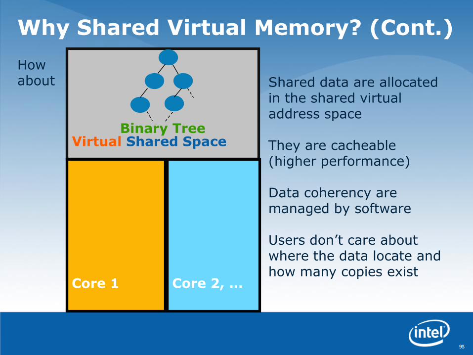
Why Shared Virtual Memory? (Cont.)
95
Virtual Shared Space
Core 1
Binary Tree
Core 2, …
Shared data are allocated in the shared virtual address space
They are cacheable (higher performance)
Data coherency are managed by software
Users don‟t care about where the data locate and how many copies exist
How about

96
Shared Virtual Memory Model
VA Shared
Core 1 virt addr space Core 2 virt addr space
Shared dataare allocated
here
VAPrivate
VAPrivate
VA Shared

97
Shared Virtual Memory Model
VA Shared
Core 1 virt addr space Core 2 virt addr space
SW can indicate regions being exclusively
accessed:Owned by core 1
VAPrivate
VAPrivate
VA Shared

98
Shared Virtual Memory Model
VA Shared
Core 1 virt addr space Core 2 virt addr space
VAPrivate
VAPrivate
VA Shared
These regions canbe handed over:Owned by core 2

99
Shared Virtual Memory Model
VA Shared
Core 1 virt addr space Core 2 virt addr space
VAPrivate
VAPrivate
VA Shared
No particular owner:
(jointly accessed)

Partially sharedRelease consistency
Ownership
Cut down coherent overhead
100
Shared Virtual Memory Model
VA Shared
Core 1 virt addr space Core 2 virt addr space
VAPrivate
VAPrivate
VA Shared

Outline
•Motivation
•Overview of SW managed coherence
•Implementation and Optimizations
•Our results
•Challenges for future research
101

Language and Compiler Support
• New “shared” type qualifier
> shared int a; //a shared variable
> shared int* pa; //a pointer to a shared int
> shared int* shared pb; //a shared pointer to a shared int
• Static checking rules enforced by the compiler
> No sharing between stack variables
• foo() {shared int c;}
> Shared pointer can‟t point to private data
• int* shared pc;
> And more on pointer assignment and casting etc.
102

Runtime Support
• Partial sharing on page-level– Only those actually shared are subjected to consistency
maintenance
103

Runtime Support
• Partial sharing on page-level– Only those actually shared are subjected to consistency
maintenance
• Release consistency model– Consistency only guaranteed at the sync points (release,
acquire)> Significantly reduce coherence traffic
– Many applications already follow RC model> E.g. sync points: pthread_create, mutex, barrier, … > Release/Acquire can be inserted automatically at these points
104

Runtime Support
• Partial sharing on page-level– Only those actually shared are subjected to consistency
maintenance
• Release consistency model– Consistency only guaranteed at the sync points (release,
acquire)> Significantly reduce coherence traffic
– Many applications already follow RC model> E.g. sync points: pthread_create, mutex, barrier, … > Release/Acquire can be inserted automatically at these points
• Ownership rights– No coherence traffic until ownership changed– They are treated as hints (i.e. optimization opportunities)
> Fault on touch: fault if touch something owned by others> Promote on touch: promote to “jointly accessible”
105

Object Collision Detection Example: Share Memory Approach
struct Ball {
Vector position, velocity;
int area_id;
shared struct Ball* next; // balls in the area
};
shared struct Ball* areas[N];
void collision(shared struct Ball* all) {
// do collision detection
// and compute the new position/velocity
……
}
void simulate()
{
for(i=0; i<N; i++)
thd[i] = spawn(collision, areas[i]);
for(i=0; i<N; i++)
join(thd[i]);
update_area_array();
}
106

Object Collision Detection Example: Share Memory Approach
struct Ball {
Vector position, velocity;
int area_id;
shared struct Ball* next; // balls in the area
};
shared struct Ball* areas[N];
void collision(shared struct Ball* all) {
// do collision detection
// and compute the new position/velocity
……
}
void simulate()
{
for(i=0; i<N; i++)
thd[i] = spawn(collision, areas[i]);
for(i=0; i<N; i++)
join(thd[i]);
update_area_array();
}
• It‟s just like writing a pthread program• Implicit sync points at spawn, join,
the beginning and ending of collision()
107

• Lots of code are spent in dataserialization and reconstruction.
• Is error-prone and might dead-lock.• All data are sent even not used.
Example: Message Passing Approach
typedef struct Ball Ball;
struct Ball {
Vector position, velocity;
int area_id;
Ball* next; // balls in the same area
};
Ball* areas[N];
void collision(int id)
{
// receive the data objects
// and recreate the structure
for(i=0; i<N; i++) {
areas[i] = NULL;
while(recv(id, buf)) {
b = malloc(sizeof(Ball));
*b = *buf;
b->next = areas[i];
areas[i] = b;
}
}
// do collision detection// and compute the new pos/vel……
// send back new data// and free the local objectsfor(b=all; b; b=next) {new_id = get_area_id(b);send(new_id, b);next = b->next; free(b);
}}
void simulate(){// spawnfor(i=0; i<N; i++)thd[i] = spawn(collision, i);
// send data to the individual threads// and destroy the objects
for(i=0; i<N; i++) {for(b=areas[i];b;b=next) {
for(j=0; j<N; j++) send(j, b);next = b->next; free(b);
}}
// gather data back// and recreate the link listfor(i=0; i<N; i++) {areas[i] = NULL;while(recv(id, buf)) {
b = malloc(sizeof(Ball));*b = *buf;b->next = areas[i];areas[i] = b;
}}// joinfor(i=0; i<N; i++)join(thd[i]);
}
108

Optimized implementation for SCC
– Leverage shared memory (SHM) support in SCC
– Golden copy is saved at SHM, needn‟t communicate with any other nodes
– Do memcpy between cacheable private memory & uncacheable SHM
109
Linux
Core 1 Core 2
runtime
Core N
mmap
runtime runtime
…Linux mmap Linux mmap
PrivMem 1 PrivMem 2 PrivMem N
Physical Shared Memory (SHM)

Scalability on SCC
0
5
10
15
20
25
1 2 4 8 16 32
Sp
eed
up
# of cores
BlackScholes - SCC Opt
ART - SCC Opt
• Significantly improved scalability, up to 20X on 32 cores.
• More optimizations (WIP)
110

SW managed coherence vs. HW coherenceon 32way SMP server (process per core)
• Software managed coherency is as efficient as hardware cache coherency
111
0
5
10
15
20
25
30
1 2 4 8 16 32
Rela
tive P
erfo
rm
an
ce
Thread Number
Black Scholes - Hardware
Black Scholes - Software
Art - Hardware
Art - Software

Emerging usage models
• Separated coherency domains
– Whole system partitioned into multiple coherency domains
– Dynamic reconfigurable
– Mixed mode: share memory in one domain with MPI in others
112
Domain #1
Domain #2
Domain #3
Non-coherent
MPI-based

• Multiple SCC chips
– When an application is massively parallel, more SCC chips can be connected together to form a uniform wider coherency domain
Another usage models
A uniform
wider
coherency
domain
113

Summary
• We believe software managed coherency on non-coherent many-core is the future trend
• A prototyped partially shared virtual memory system demonstrates it can be:
−Easy to program
−Comparable performance vs. hardware coherence
−Adaptive to future advanced usage models
• Also opens new research opportunities
114
114

Challenges for future research
• This revived “software managed coherency” topic opens many “cold cases”
• What are the right software optimizations?
−Prefetching, locality, affinity, consistency model
−And more…
• What is the right hardware support?
• How do emerging workloads adapt to this?
Please contact us if you are interested in this topic.
115

Agenda
10:00 Welcome and Opening Remarks
10:15 SCC Hardware Architecture Overview
11:15 Today’s SCC Software Environment
12:15 Buffet Lunch – Informal discussions
13:15 Message Passing on the SCC
13:45 Software-Managed Coherency
14:15 Application ”Deep Dive”: Javascript Farm on SCC
14:45 Break
15:00 Plans for future SCC access
15:30 Q&A
16:30 Adjourn
116

Adam Welc, Richard L. Hudson, Tatiana Shpeisman, Ali-Reza Adl-Tabatabai
Programming Systems Lab
JavaScript Farm on SCC
Intel Labs Single-chip Cloud Computer Symposium February 12, 2010

ParWeb Project
•Today‟s web applications
–Becoming more and more sophisticated and complex (productivity suites, photo editing, games, etc.)
–Still largely sequential, despite availability of multi-core and many-core, due to limitations of programming tools and support infrastructure
•Project goals
–Flexible and expressive parallel programming model
–Utilize all available resources to maximum
118

JavaScript
•Object-oriented dynamically typed scripting language
•Designed for productivity
–One of the most popular web technologies
–One of the most popular scripting languages
•Limited support for parallelism
–Web workers (in HTML 5) designed to increase GUI responsiveness
–Web workers can communicate with HTTP servers via message passing
119

Parallelizing JavaScript on SCC
•Offload computation from the client (browser) to the server farm on SCC
•Utilize as many off-the-shelf components as possible for high productivity
–Client and server code written in pure JavaScript
–Unmodified client (browser) running on host
–Largely unmodified execution engine (based on Google‟s v8) for servers running on SCC
–Standard libraries and tool-chain used on SCC
120

Web App Architecture
•HTTP server‟s scripting engine typically used for dynamic web page generation
•Can be used for general-purpose computation as well
HTTP SERVER
SCRIPTING ENGINE
JS (V8), PHP, …
JS SCRIPTING ENGINE (v8)
content
request
web
page
BROWSER
121
WEB WORKERS

Single-chip Cloud Computer
HTTP SERVER
SCRIPTING ENGINE
JS (V8), PHP, …
content
request
web
page
SCC
PCIe
122
JS SCRIPTING ENGINE (v8)
BROWSER
WEB WORKERS

Enabling SCC
HTTP SERVER
SCRIPTING ENGINE
JS (V8), PHP, …
content
request
web
page
SCC
PCIecompute
request
compute
response
HTTP SERVER
SCRIPTING ENGINE
JS (V8), PHP, …
123
JS SCRIPTING ENGINE (v8)
BROWSER
WEB WORKERS

Web Workers Actors
HTTP SERVER
SCRIPTING ENGINE
JS (V8), PHP, …
content
request
web
page
SCC
PCIecompute
request
compute
response
HTTP SERVER
SCRIPTING ENGINE
JS (V8), PHP, …
ACTORS
124
JS SCRIPTING ENGINE (v8)
BROWSER
ACTORS

Compute Servers
HTTP SERVER
SCRIPTING ENGINE
JS (V8), PHP, …
content
request
web
page
SCC
PCIecompute
request
compute
response
COMPUTE SERVER
JS SCRIPTING ENGINE (v8)
ACTORS
125
JS SCRIPTING ENGINE (v8)
BROWSER
ACTORS
Infrastructure
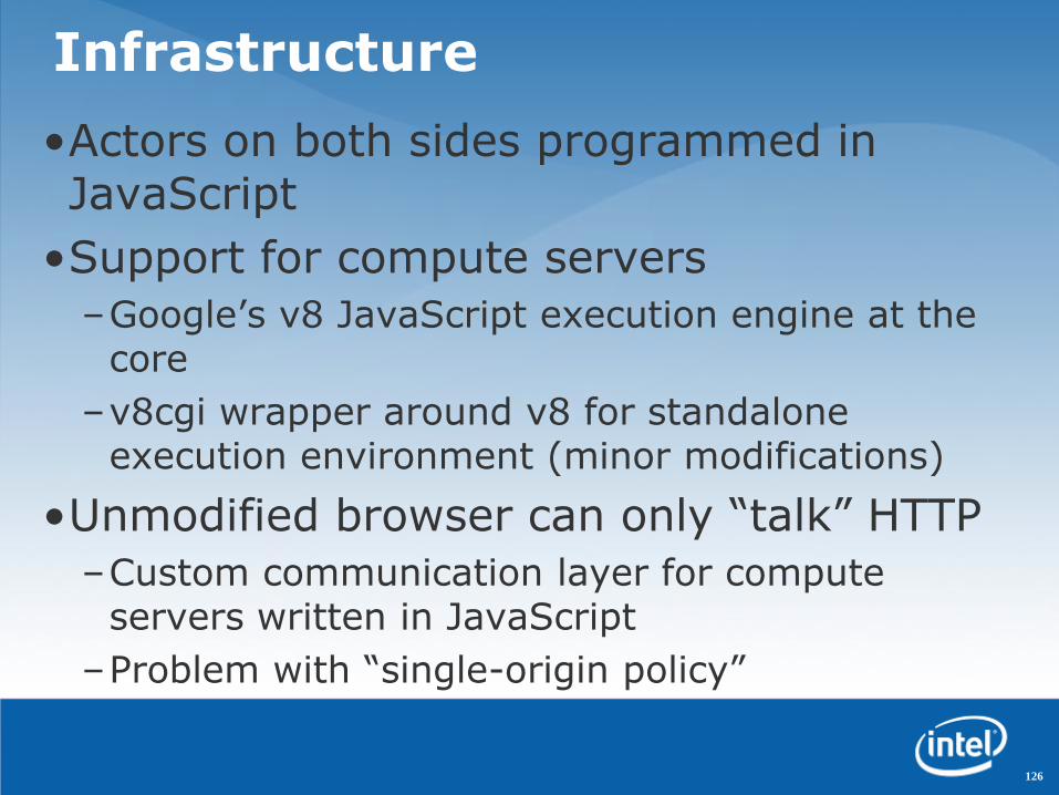
•Actors on both sides programmed in JavaScript
•Support for compute servers
–Google‟s v8 JavaScript execution engine at the core
–v8cgi wrapper around v8 for standalone execution environment (minor modifications)
•Unmodified browser can only “talk” HTTP
–Custom communication layer for compute servers written in JavaScript
–Problem with “single-origin policy”
126

Single-origin Policy
•A script downloaded from a server can only exchange messages with that single server
•Except…
–A script can run in global scope or in “iframe”
–Multiple iframes created by the same program can be downloaded from different servers
–Variables and function definitions can be shared between global scope and iframes
•Solution – generic iframes downloaded from compute servers and used to bootstrap computation defined in global scope
127

Case Studies
•Parallel ray-tracer (presented here) and parallel physics engine
•Identical infrastructure
•Parallel ray-tracer based on sequential JavaScript app from Google‟s JavaScript v8 benchmark suite
•Two different approaches for work distribution
–Dispatcher
–Direct
128

Dispatcher Approach
•Reduce host/device network traffic
•Utilize 8 cores (for simplicity):
–Dispatcher actor on core 0
–Worker actors on the remaining 7 cores
–Dispatcher talks to browser and deals work
–Workers perform actual computation SCC
PCIe
129
JS SCRIPTING ENGINE (v8)
BROWSER
ACTORS
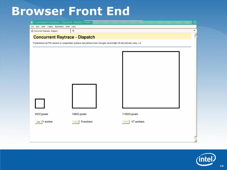
Browser Front End
130

Dispatcher Results
131
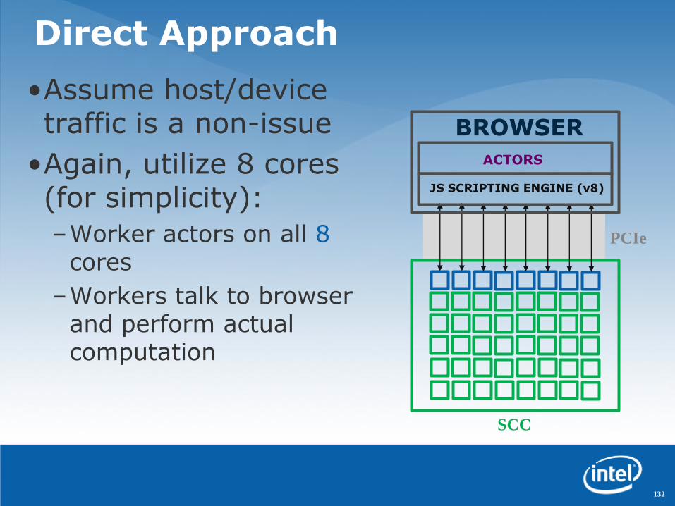
Direct Approach
•Assume host/device traffic is a non-issue
•Again, utilize 8 cores (for simplicity):
–Worker actors on all 8cores
–Workers talk to browser and perform actual computation
SCC
PCIe
132
JS SCRIPTING ENGINE (v8)
BROWSER
ACTORS
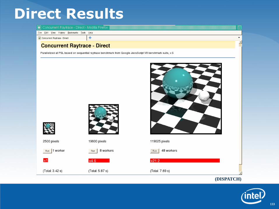
Direct Results
133
(DISPATCH)

Direct Results
134
(DISPATCH)

Results Summary
•Actor distribution does make a difference
•Both approaches yield similar scalability for large pictures – ~50%
•Host/device network effortlessly handles 48 independent connections
–Direct approach is ~2x faster than dispatcher approach
–Multiple worker sending rendered image piece-wise help hiding communication latency
135

Conclusions
•Prototyped a server farm on SCC
•Infrastructure utilizes mostly off-the-shelf software components and tools
•Demonstrated good scalability
•Future work includes
–Better implementation of the communication layer in a plug-in (no iframes!)
–Experimentation with other applications that exercise the actor model (e.g. inter-actor communication and collaboration)
136

Agenda
10:00 Welcome and Opening Remarks
10:15 SCC Hardware Architecture Overview
11:15 Today’s SCC Software Environment
12:15 Buffet Lunch – Informal discussions
13:15 Message Passing on the SCC
13:45 Software-Managed Coherency
14:15 Application ”Deep Dive”: Javascript Farm on SCC
14:45 Break
15:00 Plans for future SCC access
15:30 Q&A
16:30 Adjourn
137

Agenda
10:00 Welcome and Opening Remarks
10:15 SCC Hardware Architecture Overview
11:15 Today’s SCC Software Environment
12:15 Buffet Lunch – Informal discussions
13:15 Message Passing on the SCC
13:45 Software-Managed Coherency
14:15 Application ”Deep Dive”: Javascript Farm on SCC
14:45 Break
15:00 Plans for future SCC access
15:30 Q&A
16:30 Adjourn
138

Bob Noradki
Microprocessor & Programming Research Lab
SCC Co-Travelers Program
Intel Labs Single-chip Cloud Computer Symposium February 12, 2010

SCC Co-Travelers ProgramStarter Package for Participants
• Access to an SCC System: Remote access or at your site –
depending on your research needs
• Documentation: SCC Architecture, How To Guides, RCCE
Messaging Library Spec, SCC APIs, more
• Open Source SW: Sample Linux image for SCC, several workflows
ported to SCC environments
• Tools: Intel Compilers, Trace Analyzer and Collector. Math Libraries
(MKL) and Integrated Performance Primitives (IPP) may be included
• Support: SW: Self-Supporting w/in the community, HW: through
Intel Premier Support
140

SCC Co-Travelers ProgramCommunity Development
• Website to facilitate a strong community
– User-contributed software will be a key enabler
– Shared ideas to help overcome research problems
– Peer assistance on “How To” issues, design research plans
– Intel Looking for Forum/Topic Sponsors
• Regular Intel Sponsored Conferences
– Chance to present Data, discuss Results
• Frequent SCC Special Topic Workshops
– Memory, Power Mgmt, Languages, etc
– Face to Face and/or Webinars
– Community driven, not just Intel taking lead
141

SCC Timeline
Jan Feb Mar Apr May Jun Jul Aug Sep
Santa Clara
Feb 12
Germany
Mar 17
Introduction Symposia/Workshops
Research Proposal Process
Overview, Messaging LIB,
EAS, How To Use Linux
Sample
Workflows
Documentation/SW Availability
Beta
Testers
General HW Availability
Datacenter For Remote Access
Platform Availability
Registration Applications 15 Apr
Deadline
Notification
1st Week of May
Final Docs
Website Active
Workshops and Conferences
TBD
142

Research Grant Application Process
• Key Dates
– Applications Available End of Feb 2010
– Applications Close 15 Apr 2010
– Final Selection Notification 1st Week of May 2010
• Working through existing Research Grant Processes
– Academics: Research Grant Proposal thru Intel ERO
– Industry: Work with Intel Labs and Intel Field Sales
– Government: Use your Existing Intel Labs Contact
• Selection Criteria
– Will it help Intel build better Hardware?
– Will it advance the development of parallel programs for cloud and client?
– Details to be provided on the application forms
143

Questions?
• General Questions or to request an Application
• Technical Questions re: SCC Platform, Research
144

Agenda
10:00 Welcome and Opening Remarks
10:15 SCC Hardware Architecture Overview
11:15 Today’s SCC Software Environment
12:15 Buffet Lunch – Informal discussions
13:15 Message Passing on the SCC
13:45 Software-Managed Coherency
14:15 Application ”Deep Dive”: Javascript Farm on SCC
14:45 Break
15:00 Plans for future SCC access
15:30 Q&A
16:30 Adjourn
145

Agenda
10:00 Welcome and Opening Remarks
10:15 SCC Hardware Architecture Overview
11:15 Today’s SCC Software Environment
12:15 Buffet Lunch – Informal discussions
13:15 Message Passing on the SCC
13:45 Software-Managed Coherency
14:15 Application ”Deep Dive”: Javascript Farm on SCC
14:45 Break
15:00 Plans for future SCC access
15:30 Q&A
16:30 Adjourn
146