single arm recumbent bicycle - digitalcommons@calpoly
TRANSCRIPT

Single Arm Recumbent Bicycle
#92a1CPME
Final Design Review December 7th, 2018
ME 430 Winter-Fall 2018
Team Members:
Ryan Westermann [email protected] Alex Borsotti [email protected] Sean Liston [email protected]
Project Sponsor:
Quality of Life Plus Jon Monett (QL+ President and Chairman) [email protected]
Barbara Springer (QL+ West Program Manager) [email protected] Lance Iunker (Former QL+ West Program Manager)
Faculty Advisor:
Brian Self [email protected]
Mechanical Engineering Department California Polytechnic State University-San Luis Obispo
2018

Table of Contents
Statement of Disclaimer 6
Executive Summary 6
Section 1. Introduction 7
Section 2. Background 7 2.1 Technical Literature and Documents 7 2.2 Existing Products 8 2.3 Patents 10 2.4 Interviews 12
Section 3. Objectives 12 3.1 Project Goals 12 3.1.1 Problem Statement and Boundary Diagram 13 3.1.2 Needs and Wants Table 13 3.2 Quality Function Deployment Process 15 3.2.1 Overview 15 3.2.2 Customer Requirements 15 3.2.3 Engineering Specifications 16 3.2.4 Targets for Engineering Specifications 16 3.3 Specification Table 16
Section 4. Concept Design Development 17 4.1 Concept Ideation Process 17 4.1.1 Functional Decomposition 17 4.1.2 Brainwriting/Brainstorming 17 4.2 Concept Modeling 18 4.2.1 Guerrilla Prototyping 18 4.3 Selection Matrices 20 4.3.1 Pugh Matrices 20 4.3.2 Decision Matrix 20 4.3.3 Favored Concept Models 20 4.4 Concept Prototype 21 4.4 Prototype Evaluation 22
Section 5. Favored Design 23 5.1 Overall Design Description 24 5.2 Detailed Design Description 24
Senior Design Project Single Arm Recumbent Bicycle Page 2

5.3 Analysis Description and Results 25 5.4 Cost Analysis 27
Section 6. Prototype Design and Manufacture 28 6.1 Design Overview 28
Section 6.2 Design Details 29 6.2.1 Procurement 29 6.2.2 Manufacturing 29 6.2.3 Paddles 30 6.2.4 Seat Support Assembly 30 6.2.5 Top Rack 30 6.2.6 Flag Poles 30 6.2.7 Main Shaft Assembly 30 6.2.8 Front Fork Connector 31 6.2.9 Assembly 31
Section 7. User Feedback 31 Section 7.1 Testing Results 32 Section 7.2 Discussion with Lance and Nick 32
Section 8. Re-Ideation 32 Section 8.1 Concept Modeling 32 Section 8.2 Decision Matrix 33 Section 8.3 Pugh Matrix 34
Section 9. Final Design 34 Section 9.1 Finalized Steering Design 34
Section 10. Manufacturing 38 Section 10.1 Upper Rotor Mount 38 10.2 Lower Rotor Mount 40 10.3 Caliper Mount 41 10.4 Assembly 41 10.4.1 Steering Design Assembly 41 10.4.2 Braking and Shifting Assembly 42
Section 11. Design Verification 43 11.1 Functionality Testing 43 11.2 Brake Response Test 44 11.3 Steering Lock Slip Testing 44
Senior Design Project Single Arm Recumbent Bicycle Page 3

Section 12. Management Plan 46 12.1 Project Timeline 46 12.3 Team Member Roles 47
Section 13. Conclusion 47
Section 14. Quality of Life Plus Agreement 49
References 50 Appendix A: Quality Function Deployment 51 Appendix B: Decision & Pugh Matrices 52 Appendix C: Preliminary Analysis and Testing 57 Appendix D: Concept Layout Drawings (Pre-CDR) 58 Appendix E: Concept Layout Drawings (CDR) 59 Appendix F: Complete Drawings Package (Lean to Steer) 60 Appendix G: Complete Drawings Package (Steering Lock) 72 Appendix H: CDR Purchased Parts Details 75 Appendix I: Budget/Procurement List 76 Appendix J: Analysis and Testing Details 77 Appendix K: Safety Hazard Checklist 81 Appendix L: Gantt Chart 83 Appendix N: Ideation List 85 Appendix O: Finalized Bill of Materials 87 Appendix P: User Manual with Safety Guides 89
List of Tables Table 1. Relevant Journal Articles Table 2. Researched Patents Table 3. Customer Needs and Wants Table 4. Design Specification Goals Table 5. Concept Models Table 6. Bill of Materials Table 7. Concept Designs and Descriptions Table 8. Damping Mount Test Data Table 9. Responsibility Matrix
Senior Design Project Single Arm Recumbent Bicycle Page 4

List of Figures Figure 1. Monomano Trike Figure 2. Shimano Speed Brake Lever Figure 3. NuVinci N360 Shifter Figure 4. Intrepid Tour Handcycle Figure 5. Reverse Tricycle Figure 6. Handcycle Boundary Diagram Figure 7. Portion of QFD Figure 8. Center Crank Concept Model Figure 9. CAD for Proposed Design Figure 10. Photo of Concept Prototype Figure 11. Testing Lean-Assisted Steering Figure 12. Final Design for CDR Figure 13. Steering Assembly Exploded View Figure 14. FEA on Support Bracket Figure 15. Measuring Required Turning Angle Figure 16. CAD Model of Concept Prototype Figure 17. Completed Summer Prototype Figure 18. Final Design Assembled on Bike Figure 19. CAD Model of Final Design Figure 20. Additional CAD Model of Final Design Figure 21. CAD Model of Steering Lock Rotor Mount Figure 22. CAD Model of Steering Lock Caliper Mount Figures 23-26. Manufacturing of the Lower Rotor Mount Figures 27-28. Manufacturing of the Upper Rotor Mount Figure 29. Manufacturing of the Caliper Mount Figure 30. Assembly of the Steering Lock Figures 31-32. Positioning of Bike Control Levers Figure 33. Functionality Testing Figure 34. Steering Lock Testing Figure 35. Dampener Testing
Senior Design Project Single Arm Recumbent Bicycle Page 5

Statement of Disclaimer The project described in this document is a result of a class assignment, completed at California Polytechnic State University in San Luis Obispo for the Quality of Life Plus (QL+) Program, a registered 501(c)(3) not-for-profit organization. It has been graded and accepted as fulfillment of Cal Poly course requirements and QL+ Project requirements only. Project completion and acceptance by these entities does not imply technical accuracy or reliability. Any use of information in this report is done at the risk of the user. These risks may include catastrophic failure of the device or infringement of patent or copyright laws. Neither California Polytechnic State University, its faculty and staff, nor the Quality of Life Plus Program, its Board of Directors, Officers and Staff, may be held liable for any use or misuse of this project, or for the potential risks stated. Executive Summary The goal of this report is to outline and cover the scope of work for the Single Arm Recumbent Bicycle Senior Project. The report will give an introduction of the problem, a background of the existing research or products relating to our project, the objectives of our project, our project management plan, our final design, manufacturing, testing, our project management, and final recommendations for improving the final design. The team is being supported by the Quality of Life Program, a non-profit organization that works to improve the lives of those injured in duty while serving our nation. The main focal point for this organization for our team is Barbara Springer, QL+ West Coast Program Manager and Jon Monett, QL+ President and Chairman. Up until now, there have been no bikes developed for single arm triple amputees without the aid of prostheses. Nick Kimmel, a former marine, would like to join a group of firefighters participating in a charity bike ride from Seattle, Washington to Boulder, Colorado. This fundraising event is in support of the Gary Sinise Foundation which provides mortgage-free specially adapted smart homes to wounded veterans free of charge. In order to participate, Nick requires a bike that accommodates use with only one arm and no prosthetics. Currently, Nick, a triple amputee, is equipped with a hand-powered recumbent bicycle. However, since the bike is designed to be operated with two arms, Nick is not able to steer the bike properly, and in turn, strains his body. In addition, Nick intends to use the bike without the use of prosthetics because they overheat his body and inhibit his performance. For this reason, our group is tasked with developing a single-arm recumbent bicycle that has fully functioning steering, shifting, and braking while also being reliable and durable enough to handle a 1000-mile challenge, all without the use of prosthetics. This report presents all work done by the team over the course of this project. The Cal Poly senior project is focused on the process so you will see a lot of design tools in use throughout this report that our group used to assist us in our journey through the design process. This process includes tools such as decision matrices, Gantt charts, concept prototypes, testing, and even a total redesign for our project after getting feedback from our challenger, Nick.
Senior Design Project Single Arm Recumbent Bicycle Page 6

Section 1. Introduction Nick Kimmel is a Marine Corps veteran from Washington who lost three limbs to an IED in 2011. He underwent rehabilitation in San Diego where he currently resides. Nick approached QL+ seeking a way to ride a bike with his remaining arm after attempting to ride a recumbent bike and realizing he could not properly steer. The other stakeholders for this project include Nick’s family, the bikers that Nick will be riding with, his support team for the charity ride, and hopefully other people who only have one arm. QL+ and former QL+ west coast program manager, Lance Iunker, asked three Mechanical Engineering students attending California Polytechnic State University-San Luis Obispo to adapt a current hand powered recumbent bike to be used with only one arm and no leg prosthetics, all while maintaining proper bike handling and performance. The members of the team are Ryan Westermann, Sean Liston, and Alex Borsotti. The team worked through multiple ideas of the best course of action to give Nick control over the bike and ended up developing a system that achieves that goal. Section 2. Background 2.1 Technical Literature and Documents Extensive research efforts were conducted with a wide breadth of resources in order to better equip the team for the unique challenges this project will pose. Noteworthy topics from our research of peer reviewed journals and conference proceedings were on the topics of ergonomics, biomechanics and mechanics of handcycles, and bicycle component designs. Sources such as the U.S. Department of Veteran Affairs (USDVA) and the Paralympics have published studies on hand cycling body kinetics and range of motion efficiency as well as analyses on hand cycle design efficiency and optimization. A detailed listing of relevant journal articles can be seen in Table 1.
Table 1. Relevant journal articles and conference proceedings.
Title Description
Effects of type and mode of propulsion on hand-cycling biomechanics in nondisabled subjects (Arnaud Faupin, et al. 2010)
A study investigated the range of motion of the upper limb and trunk, forces, two-dimensional fraction effective force, and torque during hand cycling.
Biomechanics in Paralympics: Implications for Performance (Morriën, Floor, et al. 2017)
A combination of physiological and biomechanical analyses to assess the efficiency. Analyses movement patterns and force generation strategies during handcycling.
Cycling Comfort Levels for Recumbent Exercise Bicycles (Yen, Chien Cheng, et al. 2013)
Subjective comfort level assessment results for users after riding to determine the optimal seat position for recumbent exercise bicycles.
Senior Design Project Single Arm Recumbent Bicycle Page 7

On the design of a recumbent bicycle with a perspective on handling qualities (Schwab, A.L., et al. 2012)
A novel approach to bicycle design for handling qualities is presented. The design method is introduced through a case study in which a new front-wheel drive recumbent bicycle is developed.
Energy cost and mechanical efficiency of riding a human-powered recumbent bicycle (Capelli, Carlo, et al. 2008)
This study quantifies the capability of converting metabolic energy in useful mechanical work by measuring mechanical efficiency of riding a recumbent bicycle.
2.2 Existing Products One of the first steps taken in this project was to benchmark existing products and patents to evaluate their effectiveness on the market and robustness of design. All of these products have the potential to be utilized or influence design aspects of the project. The initial product search was for bikes that are controlled with one arm. One such product is the MonoMano one handed trike as seen in Figure 1. This trike has centralized one-handed steering, shifting and braking. Unfortunately, it is still powered with the feet. Another product that combined control functions is a standard Shimano shifter and brake lever. Depicted in Figure 2, this lever can be connected to existing bikes and is able to be controlled with one hand. Most bike designs that we have found incorporate some sort of mechanism similar to this one.
Figure 1. A MonoMano trike designed for one-handed steering, shifting, and braking.
Figure 2. Shimano speed shift-brake rear lever.
Other bike transmissions were also explored as a potential alternative to a standard manual gear shifter. The NuVinci N360, pictured in Figure 3, is a continuously variable transmission (CVT) that eliminates fixed gears and shifting clutch(es) in favor of gradually changing torque ratios controlled by rotating the shifter grip.
Senior Design Project Single Arm Recumbent Bicycle Page 8

Figure 3. The NuVinci N360 shifter and rear hub.
Our product search then expanded into different designs for hand cycles. Existing handcycles come with either an asynchronous or synchronous crank setup, but synchronous setups are the more efficient and less strenuous design for long term riding. Hand cycles can have reclined or upright seats. Upright seats are described as more desirable for casual biking while reclined seats are more suitable for longer riding periods. There are two steering options for hand bikes: fork-steer and lean-to-steer. Fork-steer uses a traditional frame where the fork turns independently while the lean-to-steer has a two-piece frame where the top frame swivels over the bottom frame and the front wheel turns along with the seat. The bike that our team is tasked with repurposing is the Intrepid Estrada, which is a fork-to-steer bike. It can be seen in Figure 4 part (a).
(a) Fork-to-steer (b) Lean-to-steer handcycle.
Figure 4. (a) Intrepid Tourer Handcycle similar to the one used in this project. The steering is controlled
with the hands of the rider. (b) The pivot point can be seen located on the rear axle so when the rider leans to one side the bike steers to that same side.
Senior Design Project Single Arm Recumbent Bicycle Page 9

Later in our design process, we came across a different style of bike that we think may be useful. This bike has two wheels in the front and one wheel in the back, which we refer to as a reverse tricycle (see Figure 5). This style of bike is more stable than our current style of bike (which has two wheels in the back and one in the front). It is more stable because unlike the Intrepid wheel the front wheel doesn’t turn over at low speeds. For this reason, the rider has more control over the bike’s direction and handling. This added stability in the front could be a desirable feature of our design.
Figure 5. Reverse tricycle. Foot-powered recumbent tricycle that steers with the front wheels
2.3 Patents Another area of research the team delved into was design patents. Table 2 provides an abbreviated list of the relevant patents found as well as a brief description of each design.
Table 2. List of researched patents. Patent Number Patent Title Description
US6070894A Arm-powered wheeled
vehicle with bicycle-type cranks
An arm-powered wheeled vehicle that supports a rider in a prone or kneeling position to use crank arms radially displaced by 180 degrees to influence rear propulsion.
Senior Design Project Single Arm Recumbent Bicycle Page 10

US5516133A Steering stabilizer for bicycles
A steering stabilizer utilizing a hydraulic fluid is secured to the frame of the bicycle to provide steering resistance.
US4653613
Rotating grip brake for bicycles
A rotation actuated internal lever braking system for bicycles. Braking is applied by rotation of a handlebar grip through a lever system.
Senior Design Project Single Arm Recumbent Bicycle Page 11

US5354084A
Hand propulsion and steering dampening for
three-wheel vehicle
A stabilizing dampener between front and rear frame sections provides smooth steering and inhibits undesired, inadvertent, side to side movement of the rider's body.
US6244611 Bicycle seat harness A harness that secures the rider to the bicycle seat.
2.4 Interviews Nick was personally interviewed by the team in order to identify his personal expectations for the project. His hopes are that he has full control over the bicycle without using any prostheses on his legs. He is also concerned that with the current angle of the bike, he will end up sliding down and can’t remain seated in the bike very well. Technical information such as Nick’s sitting position preference, his body measurements, and the identification of the specific technical limitations of his current bike were acquired for future reference. The team was informed that they would be provided with a hand-crank, recumbent bike for testing and prototyping design solutions. Once a functional, finalized design is reached, the team will purchase materials to build that design and the finalized design will be implemented into the purchased pre-existing hand-powered bicycle. Section 3. Objectives 3.1 Project Goals This project does not have many restrictions on it, leaving the team to be creative and hopefully come up with a solid solution. The problem arose when Nick was unable to ride the two-crank recumbent bike he purchased. The primary goal of this project is to solve that problem by adapting the existing bike in some way. Ideally, Nick would have full control of the bike without having to contort his body in any way, as
Senior Design Project Single Arm Recumbent Bicycle Page 12

well as being able to enter and exit the bike on his own. Since this bike will likely be used for 1000 miles and years to come, it should be sturdy enough and easy to maintain so that a new one doesn’t have to be ordered to replace the current bike. 3.1.1 Problem Statement and Boundary Diagram Below is the formal problem statement for our senior design project: Nick, a combat wounded marine, is a triple amputee. He wants to complete a 1000-mile bike ride on his hand-powered recumbent bike, but his bike is set up for riders with two arms. The bike’s current setup strains his body and limits his steering ability. Our task is to adapt his bike to allow proper function with one arm and no prosthetics so that Nick can achieve his goal.
After developing the problem statement, our team then worked on creating a boundary diagram. A boundary diagram is a way of taking an image of the project or product we are working on for our design project and showcasing what we have control over. Specifically, it allows the sponsor and team alike to see what parts of the product we can influence with our design and what parts of the product we don’t have control over. For our boundary diagram, we found that we have control over the brakes, drivetrain, crank, and steering linkage that will be implemented into our design. While we won’t change the bike’s geometry, we do have control over linkages or parts that can be added to it.
Figure 6. Boundary diagram showing project scope. The picture above is the same Intrepid Tourer recumbent bike Nick would be using and shows the dotted area over which we have control for our
project. 3.1.2 Needs and Wants Table Through our initial meeting with Lance and phone call with Nick, we were able to develop our list of customer needs and wants. These needs and wants are outlined in Table 3. Anything that is necessary for
Senior Design Project Single Arm Recumbent Bicycle Page 13

the success and completion of this project is listed as a customer need. Any parameter that would provide an added benefit to the bike, but will not dictate the overall success of the project if they are not met, is listed as a customer want. As an example, ‘rider must have full control over the system’ is listed as a human factor need requirement. Nick will potentially be riding for 1000 miles on this bike and we do not want his hand to be negatively impacted from an uncomfortable grip. As a human factor want requirement, an ‘autopilot mode’ would be a nice addition. This would keep the bike traveling in a straight line while the rider reaches for water or any other stored items. It would be an additional benefit with no drawbacks if it is developed once all the customer needs are met.
Table 3: Customer Needs and Wants. Requirement
Category Description of Customer Needs Description of Customer Wants
Geometry Recumbent bike must not exceed width of road shoulder or interfere with traffic.
Adapted bike must not be much larger than current design.
Kinematics Rider of bike must have proper steering. Bike must have proper and reliable shifting.
Bike must ride smoothly.
Forces High Efficiency/Low Friction. Responsive Steering.
Bike should be lightweight to make riding up hills easier.
Materials Materials should be strong to withstand 1000 miles & normal impacts.
Lightweight and inexpensive materials would be a nice bonus.
Safety
Rider must be secured in chair. Bike must be stable as to not roll over. Rider must have full control over the system.
N/A
Human Factors Handle grip should be comfortable. Strain on rider’s body should be minimized.
Seat should be comfortable. Easy access to bike (ingress/egress). ‘Autopilot mode’ to continue straight.
Production The existing bike should be modified. Using existing technology would keep maintenance simple and costs down.
Transportation Bike should fit into Nick’s truck or standard size trailer.
Operation Bike should be quiet with minimal wear. Bike should operate in hot, cold, rainy, and sunny conditions.
Maintenance
Bike should be serviceable by any bike tech or bike shop. Bike parts should be easily replaceable or swapped out.
Bike should have normal service intervals. Bike parts should wear out or need service at normal time durations.
Cost Must keep the cost at or below the budget stated by QL+. N/A
Senior Design Project Single Arm Recumbent Bicycle Page 14
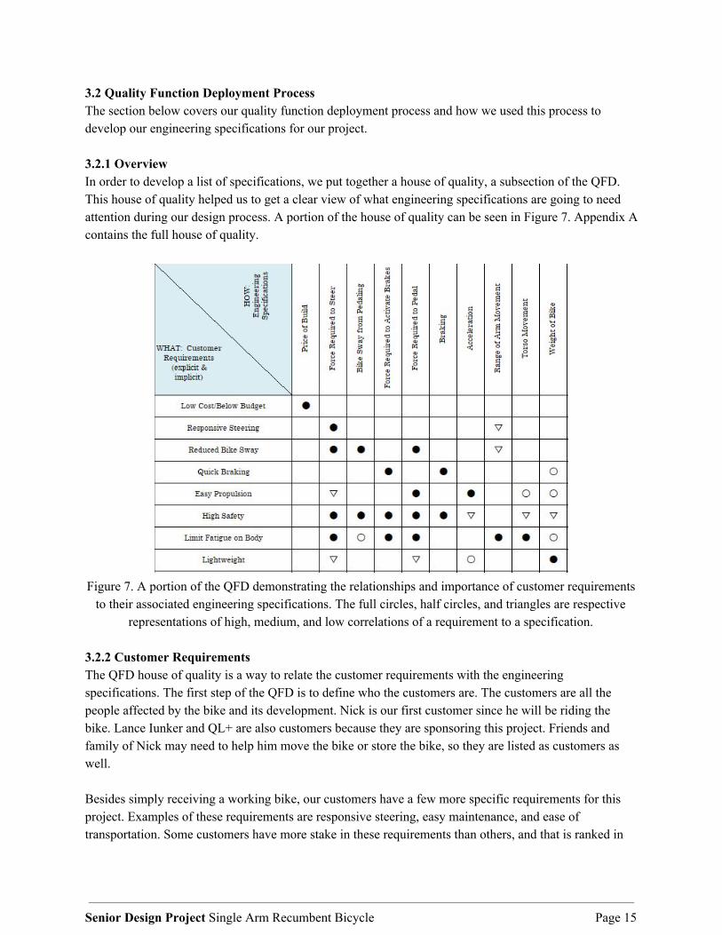
3.2 Quality Function Deployment Process The section below covers our quality function deployment process and how we used this process to develop our engineering specifications for our project. 3.2.1 Overview In order to develop a list of specifications, we put together a house of quality, a subsection of the QFD. This house of quality helped us to get a clear view of what engineering specifications are going to need attention during our design process. A portion of the house of quality can be seen in Figure 7. Appendix A contains the full house of quality.
Figure 7. A portion of the QFD demonstrating the relationships and importance of customer requirements
to their associated engineering specifications. The full circles, half circles, and triangles are respective representations of high, medium, and low correlations of a requirement to a specification.
3.2.2 Customer Requirements The QFD house of quality is a way to relate the customer requirements with the engineering specifications. The first step of the QFD is to define who the customers are. The customers are all the people affected by the bike and its development. Nick is our first customer since he will be riding the bike. Lance Iunker and QL+ are also customers because they are sponsoring this project. Friends and family of Nick may need to help him move the bike or store the bike, so they are listed as customers as well. Besides simply receiving a working bike, our customers have a few more specific requirements for this project. Examples of these requirements are responsive steering, easy maintenance, and ease of transportation. Some customers have more stake in these requirements than others, and that is ranked in
Senior Design Project Single Arm Recumbent Bicycle Page 15

the section to the left of the requirements. All these customer requirements were placed on the left side of the QFD and are things that the sponsor and recipient of the project hope to receive. After compiling the list of customer requirements and our list of customers we then compared each customer requirement to each customer. From this comparison, we gave a numerical value from 1-10 on how important that requirement was to the specific customer. By doing so, we were able to see which customer requirements mattered the most and least. Also, we compared these requirements against current products to see how well they fulfilled the requirement. For our QFD, we looked at Nick’s current recumbent bike and his one-armed wheelchair. We then gave a numerical value from 1-5 on how well that product fulfilled the requirement. All of these requirements are listed in Appendix A or our QFD. 3.2.3 Engineering Specifications On the top of the house of quality is the section for engineering specifications as shown in Figure 7. This part of the table includes measurable values such as force required to steer, deceleration, and seat angle. We compiled this list by coming up with a measurable specification we could apply to each requirement. After doing so, we found the intersection of engineering specifications columns with the customer requirements rows. By doing so, it allowed us to see how each specification related to each requirement. We used a symbol to define how strong the relationship was between the two. The closed black circle signified that the relationship was strong, the open circle signified that the relationship was moderate, and the open triangle signified that the relationship was weak. By doing so, we were able to see which measurable specifications were most crucial to our design. 3.2.4 Targets for Engineering Specifications After finishing our specifications list, we then set a target for each specification that we hoped to achieve in our design. We placed these targets in the bottom of the QFD in the engineering targets section. After coming up with a target or goal for each specification, we then compared these targets against current products just like we did for our customer requirements. We assigned a number from 1-5 on how well that product hit the target for each engineering specification. Once again, these targets are spelled out in Appendix A. 3.3 Specification Table All the parameters in the target section of the house of quality can be organized into a list of specifications. Table 4 is the table of specifications including target values and risk level. The risk level code is Low, Medium, High where the higher the risk, the more difficult we expect it will be to meet that requirement. The highest risk specifications included parameters such as Steering Force and Pedaling force. We want to limit the required pedaling force because this will hopefully keep Nick comfortable and able to propel the bike. The compliance column refers to the methods we will use to determine if the goal is met. A, I, S, and T stand for Analysis, Inspection, Similarity to existing designs, and testing, respectively.
Senior Design Project Single Arm Recumbent Bicycle Page 16

Table 4. Design specification goals.
Spec. # Parameter Description Target (units) Tolerance Risk Compliance
1 Total Cost $2000 Max. Medium I 2 Flat Ground Steering Force 10 lbs** Max. High T 3 Brake Actuation Force 5 lbs** Max. Low T 4 Flat Ground 1st Gear Pedal Force 10 lbs** Max. High T 5 Range of Arm Movement 10 - 15 in ± 5 in Medium T, I 6 Body Movement 3 in ± 1 in Low I 7 Weight 250 lbs** ± 50 lbs Low I 8 Service Intervals 100 miles Min. Medium T, A, S 9 Part Fatigue 15000 Cycles Min. Medium A, S
** signifies that these targets will be modified later to fit Nick’s needs. Section 4. Concept Design Development
4.1 Concept Ideation Process
After developing our design specifications, we moved into the next phase of our senior project, concept design development. For this section, we began tackling our given problem statement and worked towards coming up with the best solution to solve the problem. The first step in this process was the ideation phase. In this phase, we listed the main aspects of our problem statement and came up with as many ideas as possible to solve those problems. 4.1.1 Functional Decomposition The first step for our ideation was to perform a functional decomposition. To do this ideation, we listed the five major functional aspects of the entire bike: steering, cranking, braking, shifting, and comfort. We recognized our project focuses primarily on steering and cranking because the current braking and shifting systems already function well and comfort is more of a consideration to keep in mind while designing our system. Nevertheless, we spent time utilizing idea generation strategies such as brainstorming and brainwriting to examine how each of these functions could be performed by and improved for a user with one arm. 4.1.2 Brainwriting/Brainstorming The two major methods for generating ideas for our functions were brainwriting and brainstorming. Brainstorming works by coming up with as many solutions to a problem as possible while avoiding judgement or questioning of ideas being given. Through brainstorming, the group worked together to nurture as much idea growth as possible for each given challenge on the design. An immense quantity of ideas was obtained through brainstorming, allowing us to explore diverse concepts and draw upon each other’s ideas for inspiration. Similarly, brainwriting was used by having each person come up with as many solutions as possible; however, each person came up with ideas silently by writing them down on a
Senior Design Project Single Arm Recumbent Bicycle Page 17

piece of paper. Everyone needed to come up with five ideas in a span of three minutes at which time the papers were traded between participants. This strategy worked well because it allowed each person to see other people’s ideas and build on them. By utilizing each of these techniques, it allowed our group to create solutions for each of the sections from our functional decomposition. We were able to come up with well over a hundred different solutions which we later refined to mold into our final concept selection. These ideas can be seen in Appendix B. 4.2 Concept Modeling
After performing our concept ideation, we then built concept models to showcase some our our ideas. Building concept models is a useful way of spurring creativity and imagery in the mind. The mind can create wonderful things, and sometimes those things are so wonderful as to be impossible. Concept modeling is a rough prototyping method which allows the engineer to orient their mind with the system at hand and imagine the limitations of said system. During the process of concept modeling, our group used toothpicks, rubber bands, paper cups, and hot glue to construct miniature recumbent bikes with rough renditions of our design ideas. This gave us some spacial awareness of how each part would fit on the bike and what a final product might look like with blurred vision.
4.2.1 Guerrilla Prototyping
Several concept models were created to help facilitate the generation of ideas. During this session we focused on the functions steering and cranking. By building small 3D models, we were able to see where certain aspects of our designs would be located on the bike and how they would roughly function. Table 5 shows each of our concept prototypes and describes each one.
Senior Design Project Single Arm Recumbent Bicycle Page 18

Table 5. Concept Models
Concept Model Description
This model demonstrates two concepts focusing on steering: a central cranking mechanism and a shoulder steering mechanism. The central cranking concept is designed to eliminate the swaying caused by unbalanced cranking by moving the crank in line with the front tire. The shoulder steering is intended to allow the rider to utilize other parts of their body to help steer.
Several cranking designs are introduced in this model: a reduction of the current setup to one crank, moving the crank down by the hip, changing the crank rotation orientation, and a rowing machine design where propulsion is provided by pulling a cord attached a flywheel connected to the gear train.
This concept model is intended to simulate the movement of a singular central crank. The central crank is supported by its ends with two rods for stability.
This assembly is a representation of the two section design of the bike. The front portion of the bike can roll side to side independently from the rear section to perform turns. The rear section is rigid and follows the movements of the front section. This served as a useful means for testing how applying variable forces on different areas of the bike affected turning behavior.
All of these designs seemed feasible and were worthy of looking into, but we found that the best strategy to determine the concept prototype of our choosing was to utilize selection matrices to refine our options. By using the Pugh and decision matrices, we were able to reduce our options using controlled convergence and pick best option to tackle our problem.
Senior Design Project Single Arm Recumbent Bicycle Page 19

4.3 Selection Matrices
Selection matrices are a tool used to organize ideas and rate them based on previously determined criteria. Our criteria were taken from our specification goals table which was derived from our QFD house of quality. We specifically used Pugh matrices and a decision matrix to help us determine which design ideas were the best.
4.3.1 Pugh Matrices
After creating lists of ideas for each function found in the ideation phase, we developed Pugh’s matrices - which may be found in Appendix B - for the ideas of each function in order to evaluate the quality of each design. A Pugh matrix is constructed by placing all the design ideas in the left of all the rows and all the specifications at the top of all the columns. Each design idea is ranked better, worse, or the same than the existing solution - this is represented by placing a one, zero, or negative one in the cell at the intersection of a design idea and specification criterion. At the end, a sum is taken for each design decision and the design with the highest number is - in theory - the best idea. This is done for the designs from each function of our functional decomposition. This matrix is simply a useful tool to help guide the mind of the engineer and should be taken with a grain of salt. Engineering judgement must be used to accurately rank each design, and sometimes the design with the highest score is not in fact a feasible design for some glaring reason. After filling out our Pugh matrices for each function, we realized that there was no need to alter the current design of braking and shifting because they are already proven designs that can be operated with one hand. Once we decided to keep the current braking and shifting mechanisms, we were able to focus on developing a few ideas pertaining to the steering and cranking functions. 4.3.2 Decision Matrix
In addition to the Pugh matrices, we utilized a weighted decision matrix to help determine which of our concepts demonstrated the most valuable characteristics with respect to other concepts. Our decision matrix may be found in Appendix B. After completing our Pugh matrices, we settled on a couple ideas that showed exceptional promise for our project. Each specification was weighted depending on the importance of that specification. For example, the cost of the bike was a factor that was not considered as important as the force required to steer the bike. Because of this, cost was rated as a one out of five while steering force was weighted as a four. This rating was multiplied by the weight given to each design decision for its ability to meet each specification. Therefore, a design that was more expensive but easy to steer will get a better score than a design that is cheap but difficult to steer. By performing this decision matrix, we then were able to reduce our problem solutions to a couple of ideas which were centered cranking, lean to steer, and shoulder steering. 4.3.3 Favored Concept Models
Two of the concepts that were seen as the most promising designs from our matrices were centered cranking and lean assisted steering. Moving the crank to the center of the bike, as seen in Figure 8, would eliminate the imbalanced forces exerted on only one side of the bike. This concept was tested by
Senior Design Project Single Arm Recumbent Bicycle Page 20

attempting to simulate how the crank would function on the current bike. Each team member took turns sitting on the bike and replicating the arm motions that the centralized design would promote.
Figure 8. Center crank concept model.
Several flaws in this concept were immediately discovered once testing began. The main issue identified was a limitation on the range of movement compared to the existing crank design. A crank in line with the center of the bike would require the rider’s right arm to be positioned directly in front of the torso. This position caused the rider’s elbow to run into their ribs as well as required greater body movements causing potential overextension of the rider’s body. Because of these negative aspects of this design, the central cranking concept was not pursued further. The second concept the team started developing was lean assisted steering. This concept involves moving the steering pivot point to behind the seat of the rider; this would allow the rider to simply tip the bike - with the seat - to either side and the bike would turn to that same side. However, several flaws with this design that were identified were the fact that it would require large adjustments to the frame and might not be something we could alter with the pre-existing model. For this reason, we then decided to focus on our concept prototype, shoulder steering, which was far more feasible. 4.4 Concept Prototype
After performing controlled convergence, we came upon our chosen prototype, shoulder steering. Our ultimate goal for creating this prototype was to test the viability of utilizing the upper body of the rider to stabilize and support steering. This model works by attaching a support rod from the fork and crank support arm to a set of paddles located by Nick’s shoulders. The paddles can rest outside Nick’s shoulder or under his armpits. By doing so, he can then properly crank, shift, steer, and brake with his right hand while also steering using his upper body and torso to help turn the front wheel over. The shoulder steering allows Nick to brace himself against the supports to maintain his current direction and then lean to either side to turn the front wheel over and turn the bike the direction he chooses. We decided to test this design
Senior Design Project Single Arm Recumbent Bicycle Page 21
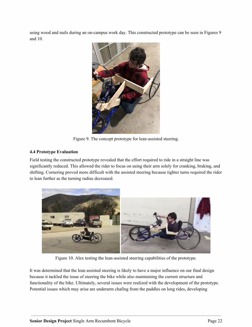
using wood and nails during an on-campus work day. This constructed prototype can be seen in Figures 9 and 10.
Figure 9. The concept prototype for lean-assisted steering.
4.4 Prototype Evaluation
Field testing the constructed prototype revealed that the effort required to ride in a straight line was significantly reduced. This allowed the rider to focus on using their arm solely for cranking, braking, and shifting. Cornering proved more difficult with the assisted steering because tighter turns required the rider to lean further as the turning radius decreased.
Figure 10. Alex testing the lean-assisted steering capabilities of the prototype.
It was determined that the lean assisted steering is likely to have a major influence on our final design because it tackled the issue of steering the bike while also maintaining the current structure and functionality of the bike. Ultimately, several issues were realized with the development of the prototype. Potential issues which may arise are underarm chafing from the paddles on long rides, developing
Senior Design Project Single Arm Recumbent Bicycle Page 22
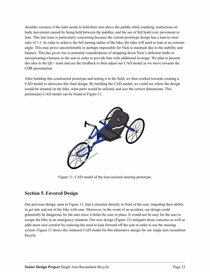
shoulder soreness if the rider needs to hold their arm above the paddle while cranking, restrictions on body movement caused by being held between the paddles, and the use of full body/core movement to lean. This last issue is particularly concerning because the current prototype design has a lean-to-steer ratio of 1:1. In order to achieve the full turning radius of the bike, the rider will need to lean at an extreme angle. This may prove uncomfortable or perhaps impossible for Nick to maintain due to the stability and balance. This has given rise to potential considerations of strapping down Nick’s deficient limbs or incorporating a harness to the seat in order to provide him with additional leverage. We plan to present this idea to the QL+ team and use the feedback to then adjust our CAD model as we move towards the CDR presentation. After building this constructed prototype and testing it in the field, we then worked towards creating a CAD model to showcase this final design. By building the CAD model, we could see where the design would be situated on the bike, what parts would be utilized, and size the correct dimensions. This preliminary CAD model can be found in Figure 11.
Figure 11. CAD model of the lean assisted steering prototype.
Section 5. Favored Design Our previous design, seen in Figure 11, had a structure directly in front of the user, impeding their ability to get into and out of the bike with ease. Moreover, in the event of an accident, our design could potentially be dangerous for the user since it holds the user in place. It would not be easy for the user to escape the bike in an emergency situation. Our new design (Figure 12) mitigates these concerns as well as adds more user comfort by reducing the need to lean forward off the seat in order to use the steering system. Figure 12 shows the rendered CAD model for this alternative design for our single arm recumbent bicycle.
Senior Design Project Single Arm Recumbent Bicycle Page 23

5.1 Overall Design Description The design shown in Figure 12 is solely focused on the steering system. Since the cranking, shifting, and braking systems are easily solved by replacing components with standard bicycle tools, we focused our CAD on modeling our steering system. The final selected single arm recumbent bicycle design focuses on using posterior lean steering. In other words, this design focuses on allowing the user to steer by leaning side-to-side which moves a steering assembly placed directly underneath the bicycle frame. By doing so, the system integrates well into the existing bicycle frame while not interfering with the user. The system works by having the user lean to either side into the paddles which rest outside the user’s torso. By leaning into the paddles, the user swings a metal assembly that lies directly behind the seat. When this happens, a set of circular rods push on the bike’s front fork which in turn rotates the wheel in the desired direction.
Figure 12. CAD model of chosen final design for CDR.
5.2 Detailed Design Description There are three main sections to our design: The front fork attachment point, the undercarriage beam, and the pivoting rack next to and behind the seat of the user. Figure 13 breaks down all main components of the assembly. The only part of the design that the user interacts with is the paddle (part 10) next to the seat. The paddles rest against the user’s ribcage and upon leaning to one side or the other, the bike is able to be steered to the same side. These paddles are angled to give clearance between the wheels when steering in either direction while still allowing the paddles to rest nicely against the user in a parallel fashion. The paddles pivot around a bolt connection to a support structure that runs against the back of the seat to a bracket (parts 8 & 9) that is part of the existing bike
Senior Design Project Single Arm Recumbent Bicycle Page 24
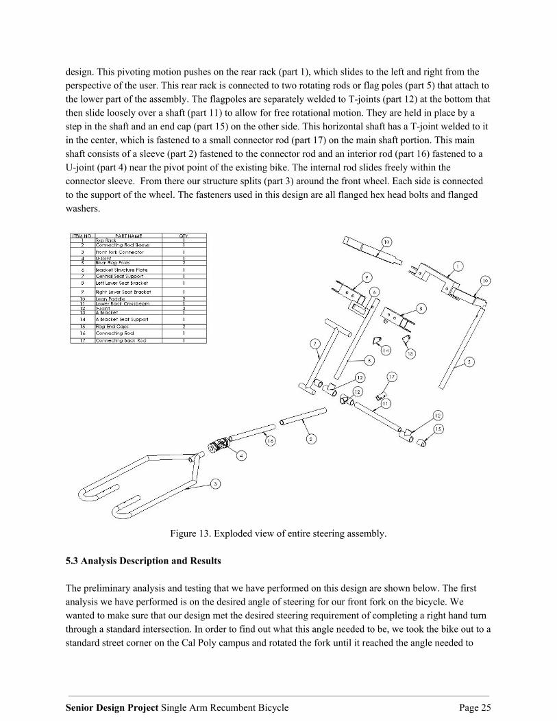
design. This pivoting motion pushes on the rear rack (part 1), which slides to the left and right from the perspective of the user. This rear rack is connected to two rotating rods or flag poles (part 5) that attach to the lower part of the assembly. The flagpoles are separately welded to T-joints (part 12) at the bottom that then slide loosely over a shaft (part 11) to allow for free rotational motion. They are held in place by a step in the shaft and an end cap (part 15) on the other side. This horizontal shaft has a T-joint welded to it in the center, which is fastened to a small connector rod (part 17) on the main shaft portion. This main shaft consists of a sleeve (part 2) fastened to the connector rod and an interior rod (part 16) fastened to a U-joint (part 4) near the pivot point of the existing bike. The internal rod slides freely within the connector sleeve. From there our structure splits (part 3) around the front wheel. Each side is connected to the support of the wheel. The fasteners used in this design are all flanged hex head bolts and flanged washers.
Figure 13. Exploded view of entire steering assembly.
5.3 Analysis Description and Results The preliminary analysis and testing that we have performed on this design are shown below. The first analysis we have performed is on the desired angle of steering for our front fork on the bicycle. We wanted to make sure that our design met the desired steering requirement of completing a right hand turn through a standard intersection. In order to find out what this angle needed to be, we took the bike out to a standard street corner on the Cal Poly campus and rotated the fork until it reached the angle needed to
Senior Design Project Single Arm Recumbent Bicycle Page 25

make the corner. Once this was done, we held the fork at that angle and took a photo. We uploaded this photo onto Solidworks and measured the angle, see Figure 15. Once this angle was measured and recorded, we looked at our CAD model to ensure our design turned the bike to the angle needed, 23°. This has lead us to ensure that the bike must be able to perform at least a 23° turn for the final model. The second analysis we performed was an Finite Element Analysis on the support brackets that are positioned on the back of the rider’s seat as seen in Figure 14. These support brackets will hold the paddles and swinging arm assembly. They were found to be more than adequate in strength with a safety factor of 3.6 in terms of withstanding the maximum loads they are expected to undergo.
(a) CAD Model of supporting bracket system (b) FEA of supporting bracket
Figure 14. Finite Element Analysis on Supporting Bracket
Senior Design Project Single Arm Recumbent Bicycle Page 26
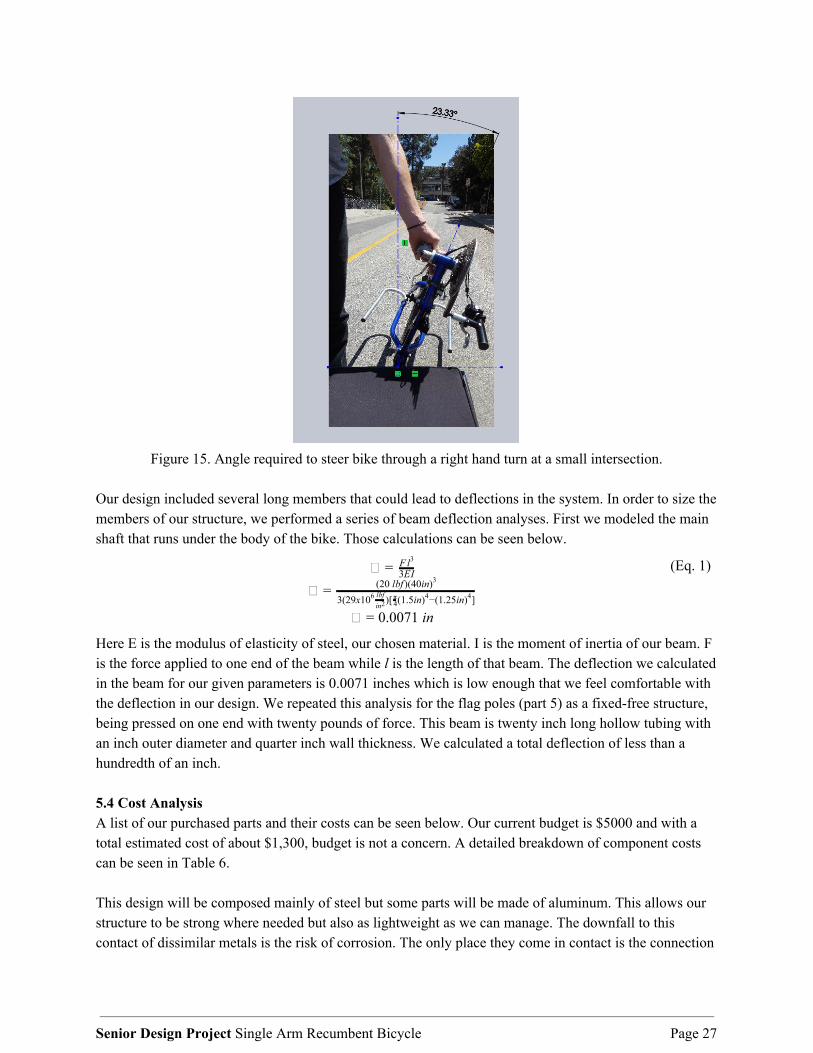
Figure 15. Angle required to steer bike through a right hand turn at a small intersection.
Our design included several long members that could lead to deflections in the system. In order to size the members of our structure, we performed a series of beam deflection analyses. First we modeled the main shaft that runs under the body of the bike. Those calculations can be seen below.
= F l3
3EI = (20 lbf )(40in)3
3(29x10 )[ (1.5in) −(1.25in) ]6 lbfin2 4
π 4 4
.0071 in= 0
(Eq. 1)
Here E is the modulus of elasticity of steel, our chosen material. I is the moment of inertia of our beam. F is the force applied to one end of the beam while l is the length of that beam. The deflection we calculated in the beam for our given parameters is 0.0071 inches which is low enough that we feel comfortable with the deflection in our design. We repeated this analysis for the flag poles (part 5) as a fixed-free structure, being pressed on one end with twenty pounds of force. This beam is twenty inch long hollow tubing with an inch outer diameter and quarter inch wall thickness. We calculated a total deflection of less than a hundredth of an inch. 5.4 Cost Analysis A list of our purchased parts and their costs can be seen below. Our current budget is $5000 and with a total estimated cost of about $1,300, budget is not a concern. A detailed breakdown of component costs can be seen in Table 6. This design will be composed mainly of steel but some parts will be made of aluminum. This allows our structure to be strong where needed but also as lightweight as we can manage. The downfall to this contact of dissimilar metals is the risk of corrosion. The only place they come in contact is the connection
Senior Design Project Single Arm Recumbent Bicycle Page 27

between the ‘flag poles’ and the ‘top steering rack’ with bolts. We will be able to put either a plastic washer or rubber o-ring to eliminate this contact as well as possibly add a cap over the bolt to prevent any liquids such as rain water from entering.
Table 6. Bill of Materials: Component list with costs
Section 6. Prototype Design and Manufacture Though we prefer the posterior lean design shown in Figure 12, we wanted to construct a prototype that Nick could test over the summer and we did not have time to fully develop that prototype. In the last few weeks of our spring quarter at Cal Poly, we decided to manufacture a prototype of the design seen in Figure 11, the lean to steer idea that sits in front of the user. 6.1 Design Overview The design and manufacture of this design are intended to be a proof of concept that Nick can test to give us feedback. By creating this design, we hoped that Nick could spot issues with the design that we could correct for our final design review and confirmation prototype. A CAD model of this concept prototype can be found below in Figure 16.
Senior Design Project Single Arm Recumbent Bicycle Page 28

Figure 16. CAD model of concept prototype
Section 6.2 Design Details 6.2.1 Procurement There are two distinct parts of our prototype design pertaining to procurement. All of the braking and shifting components will be purchased from a local bike shop in San Luis Obispo and installed directly on the bike. As for the steering system, we will need to purchase stock metal from McMaster Carr or a local shop in San Luis Obispo. 6.2.2 Manufacturing Besides the universal joint and standard fasteners, we will manufacture our entire steering assembly in house. This entails a combination of tube bending, tube notching, welding, cutting, brazing, drilling, fastening, and press fitting pins. Welding can be unreliable when it comes to angles, as warping can occur from the massive amounts of heat. Therefore we will only be welding where we need a solid connection and have the ability to control the angle.
Senior Design Project Single Arm Recumbent Bicycle Page 29

6.2.3 Paddles All dimensions are designated in drawing F.9 in the appendix. The aluminum square stock will be cut to size and at the appropriate angle on the chop saw. The rear paddle component will be drilled to create a hole for the pivot point and have the material around this point milled away to provide clearance for future assembly with the bracket slot. The two paddle halves will then be welded at the angled seam. We expect this process to take about three hours from start to finish. 6.2.4 Seat Support Assembly All dimensions are designated in drawings F.6, F.7 and F.8 in the appendix. The square steel tube supports behind the seat will need to be cut with a chop saw to size and end milled in order to create a slot to accept the paddle. Three fastening holes will be drilled in the left and right seat brackets. The bottom fastening point for the central support rod will be milled and welded to the bottom of the brackets. The support plate will have its central slot milled and will be butt welded together with both brackets to form a single unit. Holes will be drilled into the seat frame of the bike for mounting the brackets. The steel central seat support rods will be cut to length on a chop saw and the central rod will have its ends notched by the tube notcher. The flange rod ends will be drilled and tapped on a lathe and all three components will be welded together. The A brackets will be welded to the bike frame. We expect this process to take about five hours from start to finish. 6.2.5 Top Rack All dimensions are designated in drawing F.2 in the appendix. Each component will be cut to size with the chop saw. Two U-brackets will be built by welding aluminum plates together after fastener holes are milled into each face. Two aluminum stock blocks will have holes milled into their bottoms and through their sides to accept and secure the flag poles. The two blocks will be welded together with another aluminum block between them for structural support. The U-brackets will be welded in position on each side to accept the ends of each paddle. We expect this process to take about four hours from start to finish. 6.2.6 Flag Poles All dimensions are designated in drawing F.5 in the appendix. The flag poles will be cut to length on a chop saw before each one is welded to a T joint. A hole will be drilled through on one end to enable fastening to the top rack. The most difficult part of our manufacturing process is anticipated to be welding the metal tubes. Only one of our group members has experience doing this, so practice will need to take place before any welds are made. We expect this process to take about two hours from start to finish. 6.2.7 Main Shaft Assembly All dimensions are designated in drawing F.3, F.10, and F.11 in the appendix. The main shaft is a fairly complex part consisting of three separate tubes. These tubes will be cut to length on the chop saw. Holes for fasteners will be milled at an end of the inner tube, the sleeve, both ends of the small back connector, and the central T-joint. We expect this process to take about two hours from start to finish.
Senior Design Project Single Arm Recumbent Bicycle Page 30

6.2.8 Front Fork Connector All dimensions are designated in drawing F.4 in the appendix. Here is where the manufacturing process differs. So far we have just cut and welded objects or fastened them together. Here we are going to be using a tube notcher and a pipe bender. The tube notcher will be used so we can weld to the sleeve connections at either end of the fork. The pipe bender will be used to negotiate the angles called out by the drawing. We expect this process to take about six hours from start to finish. 6.2.9 Assembly This design has been developed with ease of assembly in mind. We want to be able to put pieces on the bike and take them back off without much difficulty. This means that we will only be welding things that absolutely need to be fixed together, but everything else will be connected by other means such as a fastener. The following is our plan for assembly from the seat back through the steering system. The first thing we will place on the bike are the brackets. These will be screwed directly into the seatback and connected to an existing support on the bike. A pin will be dropped through the support brackets and the paddles before being fastened on either end to create a pivot point. Clearance was left in the design for the addition of bearings if they are needed in the future. We will then fasten the paddles to the rear rack as well as the rear rack to the flag poles with pins. The flag poles will be welded into T-joints which will be slid over the lower rack crossbeam rod and fixed into place to allow free rotation. Spacers between joints and end caps will stop all lateral movement of individual T-joints on the crossbeam. The main shaft will be held together with fasteners between the lower rack T-joint all the way through the U-joint. The inner rod will be placed within the sleeve and then connected with the U-joint via a spring pin fastener. The back connector will be fastened with flanged screws and bolts to the T-joint and sleeve. The front portion of the design will be slid into the existing sleeves set into the lower front fork of the bike. Once the fork connector is slid into place, bolts and nuts will be used to fasten the front portion of the design together and a spring pin will fasten it to the U-joint. Section 7. User Feedback As stated earlier, we developed a prototype for the summer in order to test the functionality of our design with Nick. The goals for this prototype were to decide if the lean to steer idea was feasible and if so, find methods to improve the design before final design review in the fall. For reference, a photo of the completed prototype is shown in Figure 17.
Senior Design Project Single Arm Recumbent Bicycle Page 31

Figure 17. Senior project team with completed summer prototype Section 7.1 Testing Results During the summer, Lance brought the bicycle with the installed lean-to-steer prototype down to San Diego to perform the testing with Nick. Due to timing issues, the team could not make it, but Nick was able to tell Lance about his concerns with the design. Lance reported these findings back to the team stating that the lean-to-steer idea wouldn’t be able to meet Nick’s needs. He stated that Nick had issues with the weight of the design and how it constrained his body while sitting in the cockpit. In order to combat these issues, Nick and Lance suggested some new and alternative ideas for controlling the steering on the bike. Section 7.2 Discussion with Lance and Nick After discussing with Nick and Lance, they proposed a new concept to allow Nick control over the steering on the bike. They suggested that instead of creating a design that allows Nick to steer the bicycle it would be more practical to develop a design that lets Nick lock the steering in a straight configuration. He stated that he had some control over the steering, but that the bicycle would wobble when he tried to pedal fast or hard. In order to do so, we brainstormed a couple of new ideas. All these ideas were focused on keeping the bike light, minimizing constraining Nick, and allowing Nick to lock the steering easily with his right hand. Section 8. Re-Ideation Section 8.1 Concept Modeling After coming to the conclusion that we would need to adjust the steering design, we immediately began the re-ideation process. We started this process by brainstorming multiple ideas that would allow Nick to
Senior Design Project Single Arm Recumbent Bicycle Page 32

lock the steering at any point. These brainstormed ideas can be seen in Table 7 followed by a description. These ideas could be used in conjunction with one another.
Table 7. Concept designs and descriptions
Concept Description
Rotor/Caliper Mechanism
This design would consist of a rotor and caliper that would be mounted in some way to the frame. The rotor would be rotated on the bicycle and the caliper would be fixed. If a brake lever was pulled on this design, the rotation of the steering would
stop.
Locking Pin Mechanism
This design would consist of a locking pin and rigid metal piece. The user would push a button
that would cause the locking pin to move into the rigid piece and fix the rotation of the bicycle.
Gas Strut Damper
This design would have a gas strut installed on the bicycle in some fashion so when the bicycle was rotated the gas strut would push against the frame
and stop rotation.
Stiffer Dampener
A stiffer vibration dampener sandwich mount would be reinstalled on the bottom of the frame. This would help prevent rotation of the bicycle
and reduce wobbling.
Section 8.2 Decision Matrix Just as we had done before with our PDR and CDR designs, we performed a decision matrix on our new concepts and ideas for allowing Nick to control the steering on the bicycle. This decision matrix allowed us to compare each of our ideas against each of our specifications and narrow in on our best idea. This new decision matrix is shown at the end of Appendix B. From performing the decision matrix, we decided that the best design for our new steering system was the brake rotor and caliper mechanism. We felt that this design was the best fit for project because it would be the most lightweight, easiest to design and install, and require the least amount of maintenance. In addition, it would be easily serviceable at any bike shop. This idea was a better option over two other main concepts we had: locking pin and reverse disc brake. For the locking pin mechanism, there would be a rotating locking pin that would be released into a metal fixture. When this happened, the back would be fixed in position straight. We discussed this idea with Lance and were concerned that if this design failed Nick wouldn’t be able to adjust his steering and guide himself out of harm’s way. This thinking goes along with our reverse disc brake where the brake lever would be pulled to adjust steering and released to lock it in place. Our idea was advantageous over this
Senior Design Project Single Arm Recumbent Bicycle Page 33

one because it ensured that when Nick didn’t touch any of the braking mechanism he could steer out of traffic or any obstacles. Section 8.3 Pugh Matrix In addition to the decision matrix, we performed a Pugh matrix to compare each of our ideas against the current design. This new pugh matrix can be found in Appendix B. Even though the rotor and caliper mechanism design was one of the lowest scoring choices, we still felt like this design was the best one to pursue since it mainly performed worse compared to our current design in terms of cost, installation, and range of motion. We believed the issues with each of these categories could be easily solved with proper design and planning. Moreover, though the metrics we chose are important to our project, the single most important thing in this project is to give Nick a pleasing riding experience. Therefore, the design is required to perform its function, and perform it well. We could see from the designs listed that this would be the one to best lock the steering for Nick when he needed it to and have the adjustability to engage and disengage it at will. Section 9. Final Design After deciding on pursuing a rotor and caliper design, we worked on developing the design in Solidworks. By doing so, we hoped to determine how we would place the rotor and caliper respectively and mount them appropriately to the frame. This new steering design was added in conjunction with our finalized braking and shifting design from the CDR. A detailed breakdown of costs for the entire project can be seen in Appendix O. Section 9.1 Finalized Steering Design After much deliberation and discussion, we settled on the final design, seen assembled on the bike in Figure 18, for our rotor and caliper system. Screenshots of the CAD model for this design can be found in Figure 19 and Figure 20.
Figure 18. The final design assembled on the bike.
Senior Design Project Single Arm Recumbent Bicycle Page 34

Figure 19. CAD model of our final design.
Figure 20. Additional view of chosen final design.
Senior Design Project Single Arm Recumbent Bicycle Page 35
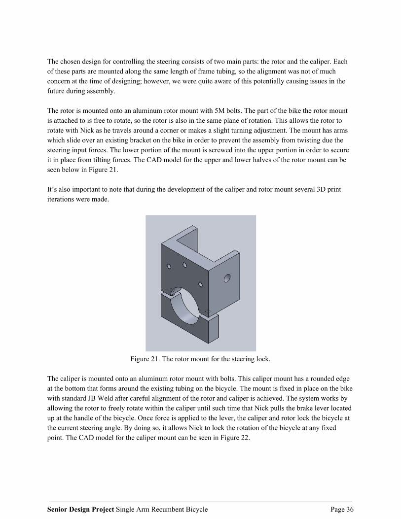
The chosen design for controlling the steering consists of two main parts: the rotor and the caliper. Each of these parts are mounted along the same length of frame tubing, so the alignment was not of much concern at the time of designing; however, we were quite aware of this potentially causing issues in the future during assembly. The rotor is mounted onto an aluminum rotor mount with 5M bolts. The part of the bike the rotor mount is attached to is free to rotate, so the rotor is also in the same plane of rotation. This allows the rotor to rotate with Nick as he travels around a corner or makes a slight turning adjustment. The mount has arms which slide over an existing bracket on the bike in order to prevent the assembly from twisting due the steering input forces. The lower portion of the mount is screwed into the upper portion in order to secure it in place from tilting forces. The CAD model for the upper and lower halves of the rotor mount can be seen below in Figure 21. It’s also important to note that during the development of the caliper and rotor mount several 3D print iterations were made.
Figure 21. The rotor mount for the steering lock.
The caliper is mounted onto an aluminum rotor mount with bolts. This caliper mount has a rounded edge at the bottom that forms around the existing tubing on the bicycle. The mount is fixed in place on the bike with standard JB Weld after careful alignment of the rotor and caliper is achieved. The system works by allowing the rotor to freely rotate within the caliper until such time that Nick pulls the brake lever located up at the handle of the bicycle. Once force is applied to the lever, the caliper and rotor lock the bicycle at the current steering angle. By doing so, it allows Nick to lock the rotation of the bicycle at any fixed point. The CAD model for the caliper mount can be seen in Figure 22.
Senior Design Project Single Arm Recumbent Bicycle Page 36

Figure 22. The caliper mount for the steering lock.
Section 9.2 Bill of Materials After deciding on our final designs for our steering, braking, and shifting systems respectively, we updated our final bill of materials needed in order to complete this project. This section is broken down by the materials or part list needed in order to build each system. The total bill of materials with all purchased parts can be found in Appendix O. Section 9.2.1 Steering System Bill of Materials As stated previously, the bill of materials for our steering system can be found in Appendix O. This bill of materials list the cost for each of our purchased parts with the manufacturer. The steering system is primarily composed of parts purchased off McMaster Carr and found at Home Depot. Both the rotor mount and caliper mount were made of out 6061 aluminum stock and appropriate fasteners and washers. Section 9.2.2 Braking System Bill of Materials The braking system is composed of upgraded purchased parts primarily from Shimano. These parts include, but are not limited to a new rotor, caliper, brake lever, and housing. These part specifications can be found in Appendix O.
Senior Design Project Single Arm Recumbent Bicycle Page 37

Section 9.2.3 Shifting System Bill of Materials The shifting system is composed of upgraded purchased parts from Shimano in order to replace the existing drivetrain with an electric model. These parts include, but are not limited to a new chainring, chain, derailleur, cassette, and shifter. These part specifications can be found in Appendix O. Section 10. Manufacturing We manufactured our entire steering lock assembly in house besides the rotor, brake cable with lever, and the brake caliper. This required a combination of manual and CNC milling, drilling, boring, and tapping. All of these manufacturing processes were done in Cal Poly machine shops with the assistance of shop technicians to oversee all operations. Section 10.1 Upper Rotor Mount The dimensions for the upper rotor mount are designated in drawing G.1. The profile of the part was CNC milled, including the most critical feature, the lower arc. This CNC operation cut the critical arc for our part. This arc can be seen below in Figure 23. This arc is critical in ensuring a correct fit on the tube it will be seated on placed on the frame. The finished CNC operation showing the completed arc on the rotor mount can be seen in Figure 24.
Figure 23. CNC milling operation for upper rotor mount
Figure 24. Completed CNC milling operation
The arms for the part were created by manually milling a channel on the mini mill and Bridgestone mill. This part involved taking the 6061 aluminum stock milled on the CNC and facing off the material to create two tabs. Initially, all the sides were faced off to the appropriate length and then the material was removed down to the appropriate length. This milling operation can be seen in Figure 25.
Senior Design Project Single Arm Recumbent Bicycle Page 38

Figure 25. Manual milling operation for upper rotor mount.
Next, the upper rotor mount was placed into a vice and a through hole was drilled using the drill press. This through hole mounts the upper rotor mount onto the frame using a bolt and washer as shown in our assembly photos in Appendix G. After the arms were milled, the bolt holes for securing the lower mount to the upper mount were drilled and tapped. Note that the holes were drilled on the lower mount first so that the bolt hole positions would be in line. This drilling operation can be seen in Figure 26.
Figure 26. Drilling operation for upper rotor mount.
Senior Design Project Single Arm Recumbent Bicycle Page 39
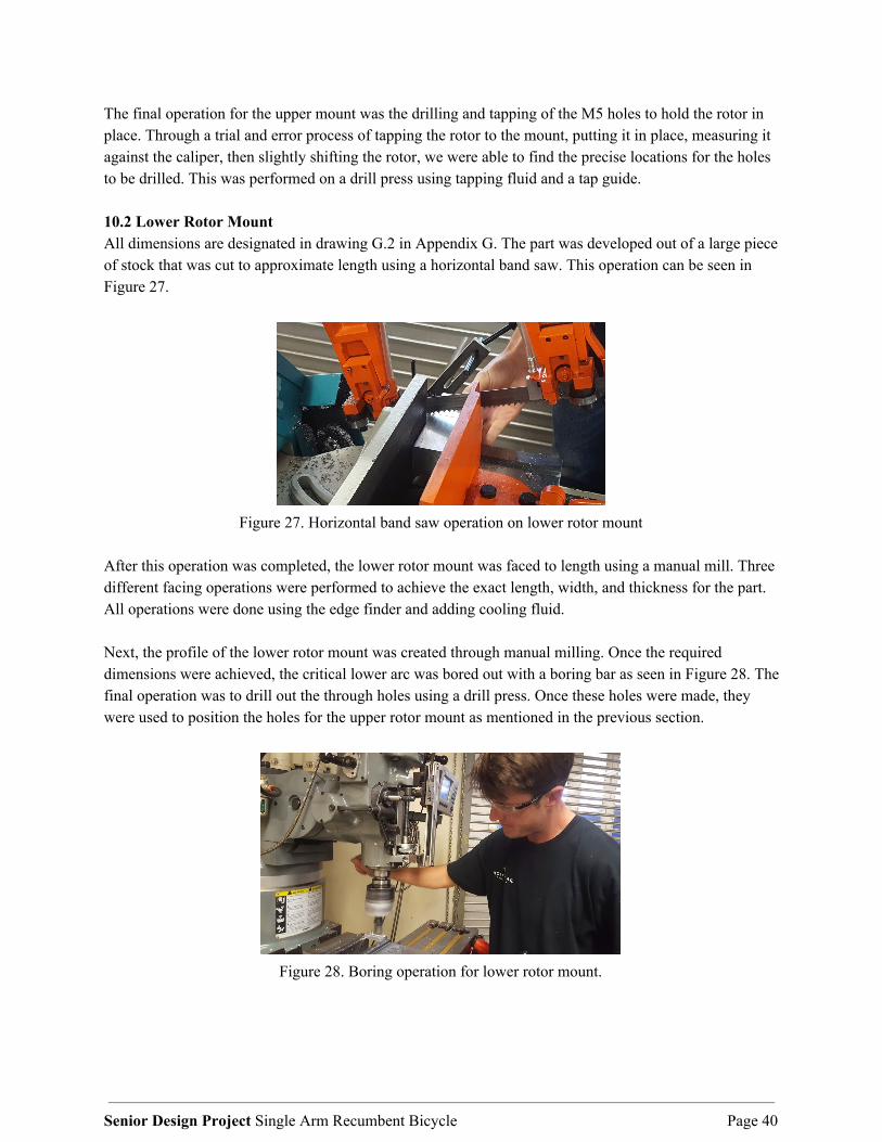
The final operation for the upper mount was the drilling and tapping of the M5 holes to hold the rotor in place. Through a trial and error process of tapping the rotor to the mount, putting it in place, measuring it against the caliper, then slightly shifting the rotor, we were able to find the precise locations for the holes to be drilled. This was performed on a drill press using tapping fluid and a tap guide. 10.2 Lower Rotor Mount All dimensions are designated in drawing G.2 in Appendix G. The part was developed out of a large piece of stock that was cut to approximate length using a horizontal band saw. This operation can be seen in Figure 27.
Figure 27. Horizontal band saw operation on lower rotor mount
After this operation was completed, the lower rotor mount was faced to length using a manual mill. Three different facing operations were performed to achieve the exact length, width, and thickness for the part. All operations were done using the edge finder and adding cooling fluid. Next, the profile of the lower rotor mount was created through manual milling. Once the required dimensions were achieved, the critical lower arc was bored out with a boring bar as seen in Figure 28. The final operation was to drill out the through holes using a drill press. Once these holes were made, they were used to position the holes for the upper rotor mount as mentioned in the previous section.
Figure 28. Boring operation for lower rotor mount.
Senior Design Project Single Arm Recumbent Bicycle Page 40
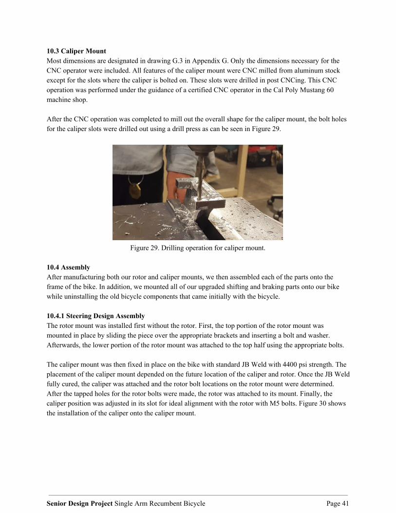
10.3 Caliper Mount Most dimensions are designated in drawing G.3 in Appendix G. Only the dimensions necessary for the CNC operator were included. All features of the caliper mount were CNC milled from aluminum stock except for the slots where the caliper is bolted on. These slots were drilled in post CNCing. This CNC operation was performed under the guidance of a certified CNC operator in the Cal Poly Mustang 60 machine shop. After the CNC operation was completed to mill out the overall shape for the caliper mount, the bolt holes for the caliper slots were drilled out using a drill press as can be seen in Figure 29.
Figure 29. Drilling operation for caliper mount.
10.4 Assembly After manufacturing both our rotor and caliper mounts, we then assembled each of the parts onto the frame of the bike. In addition, we mounted all of our upgraded shifting and braking parts onto our bike while uninstalling the old bicycle components that came initially with the bicycle.
10.4.1 Steering Design Assembly The rotor mount was installed first without the rotor. First, the top portion of the rotor mount was mounted in place by sliding the piece over the appropriate brackets and inserting a bolt and washer. Afterwards, the lower portion of the rotor mount was attached to the top half using the appropriate bolts. The caliper mount was then fixed in place on the bike with standard JB Weld with 4400 psi strength. The placement of the caliper mount depended on the future location of the caliper and rotor. Once the JB Weld fully cured, the caliper was attached and the rotor bolt locations on the rotor mount were determined. After the tapped holes for the rotor bolts were made, the rotor was attached to its mount. Finally, the caliper position was adjusted in its slot for ideal alignment with the rotor with M5 bolts. Figure 30 shows the installation of the caliper onto the caliper mount.
Senior Design Project Single Arm Recumbent Bicycle Page 41

Figure 30. Installation of caliper mount onto frame
After the rotor and caliper mount were fixed onto the bike, we rerouted the housing and brake cable line from the handle to the caliper. We routed the cable through the handle of the bicycle and attached the remaining cable to the frame using zip ties. This installation procedure allowed for a tighter cable and prevented the cable from getting caught on the chain and drivetrain. 10.4.2 Braking and Shifting Assembly The braking and shifting assemblies were purchased through and installed at a local bike shop. The lever positions were adjusted for ideal ergonomic performance. The controls for the the bike are seen in Figure 31 and Figure 32. The shifting assembly consisted of replacing the existing drivetrain and installing new a new shifter, derailleur, chain, chainring, and cassette. As stated previously, these parts allow Nick to shift the bike solely with the use of only his right hand. The braking assembly consisted of replacing the existing brake system with a new rotor and brake lever/caliper. As stated before, this upgraded system allows Nick to slow down much faster and more confidently than before. The specific upgraded part sheet can be found in Appendix O.
Senior Design Project Single Arm Recumbent Bicycle Page 42

Figure 31. Layout for the braking and steering lock levers.
Figure 32. The gear shifting levers. Bottom is shift down, Top is shift up.
Section 11. Design Verification Design verification is an important process that warrants much attention. If this step is skipped, the final design may come together and not function as intended and be considered a failure. The greatest possible verifications of a design one can perform is building a functional prototype. Our group built a functional prototype of our original design idea for Nick to test, which ultimately ended up failing the ergonomics and control aspect of its function. The failure of this test led us to completely rethink our design and develop our steering brake system. In order to validate the ability of this steering brake to perform its basic functions, we performed a series of tests, some of which were passed on the first attempt, and some which failed. These failed tests resulted in the need to reevaluate the construction of this system. All of these failed tests were evaluated and the design was changed to pass the tests. The specifics for each of these methods of design verification are detailed in the following sections. We did not perform a design verification of our upgraded shifting and braking system since these parts came from certified manufacturers and installation was performed by certified bicycle mechanics located in town. 11.1 Functionality Testing The first test we performed on our steering lock idea was a functionality test. In order to ensure that Nick would have full control of the bike, we tested the final product ourselves. At the end of the day, Nick is going to be riding this bike and it needs to function well enough for him to have full control. Therefore, our first test was to ride the bike ourselves, during which we noticed a few things. During this test we
Senior Design Project Single Arm Recumbent Bicycle Page 43

immediately noticed the steering brake, shifting buttons, and speed brake were all too spread apart from each other. It was unwieldy to operate any two of these components at the same time, which posed an issue for the rider. The most concerning observation was being unable to effectively shift gears while holding the steering lock. Since shifting is an integral part of bike functionality and this issue is directly related to the design we constructed, we modified the handle of the bike slightly to bring all control surfaces closer together. As a result of this test, the control layout is more ergonomic, particularly being easier to shift while holding the steering brake. Continuing the functionality testing, we found a 5% grade hill (measured with the “Measure” app on iPhone) and attempted to ride up it. We climbed this hill in a fairly low gear while engaging the steering lock. We performed this at different intervals of steering inclination, and the steering held each time, giving us full control over the bike. It was noted that the hill was difficult to climb because of the use of only one arm. The addition of the lower gear set helped immensely but the difficulty of using only one arm on hills with greater than 5% grade is still present. This issue can be addressed by swapping out the chainring or reducing the weight on the frame.
Figure 33. Testing functionality by riding up a 5% grade hill.
11.2 Brake Response Test The next test we performed evaluated the braking capability of bike with the newly installed brakes. We brought the bike up to 10 mph and fully engaged the brake and recorded the distance necessary to bring the bike to a full stop. We recorded an average of 12 ft braking distance over multiple trials. This distance was within our selected maximum safe stopping distance of 15 ft and was therefore determined to be acceptable. 11.3 Steering Lock Slip Testing One of the most important tests we performed was to determine if the steering lock could sufficiently hold while under the maximum forces expected during normal operation. An analysis was performed to determine the force the system is expected to withstand. This analysis can be found in Appendix I. To test if the lock would hold, we fully depressed the steering lock lever while an increasing load was applied to the center of the crank perpendicular to the crank action as seen in Figure 34. We increased this load until we reached our goal of 40 lbs which should hold Nick’s weight during operation.
Senior Design Project Single Arm Recumbent Bicycle Page 44

Figure 34. Load Input Steering Test
Testing concluded that there was a small amount of slippage between the caliper and rotor during the test. However, this slipping was reduced by pumping out air in the brake line and extending the lever play using the knob on the lever end. While there was a small amount of give between the caliper and rotor, the caliper mount itself did not move or flex. This lack of play validated the use of JB weld, but a brazing operation can be considered later to increase the attachment strength of our caliper mount. The steering lock successfully passed the test for ensuring the lock would not slip under the maximum expected circumstances for normal riding. 11.4 Vibration Dampener Mount Testing The final form of testing performed on our design was evaluating the vibration dampener mount located on the underside of the frame. An image of this is shown in Figure 35.
Figure 35. Dampener Testing
Senior Design Project Single Arm Recumbent Bicycle Page 45

A new vibration dampener was installed after determining it performed better at bringing the bike’s steering back to center. This was determined by fixing the bike to ground, attaching a fish scale to the top of steering fork, and pulling perpendicular to the bike until the foot holder contacts ground. The resulting required force to bring the bike to its final position was recorded. The results can be found in Table 8.
Table 8. Damping Mount Test Data
Damping Mount Type Average Resistive Force (lbf)
Old Damping Mount 7.0
New Neoprene Rubber 10.2
New Natural Rubber 11.5
This test concluded that the more appropriate vibration damping mount for our bicycle was the new natural rubber mount. For this reason, we uninstalled the original old damping mount and replaced it with the natural rubber model. By doing so, this mount allows the bicycle to resist turning and assist Nick better in keeping the bike centered while riding. Section 12. Management Plan At this point, our functioning product has been completed, verified, and is ready to hand off to QL+. This was made possible through careful planning, especially when a major redesign was called for. Sending the bike down to San Diego was an important step in the verification of this project since Nick was able to evaluate the direction of our work and give us valuable feedback. 12.1 Project Timeline As this is a senior design project, the timeline was dictated by the schedule of the course. This project started in January, 2018. The team proceeded with ideation, planning, decisions, rough prototyping, and design concept rendering during this time up until June 2018, when summer break started. We had the fortune of using our summer period for Nick to evaluate the product. When we came back from our summer internships in September, we received this feedback from Nick and knew we had to hit the ground running to get this new design developed and manufactured in time for the end of this course. 12.2 Gantt Chart As part of our management plan, our team created and implemented a Gantt chart to assist in the planning and execution of our design project. A Gantt chart is a type of bar chart that visually represents a project plan over time. It’s a great resource for project management because it organizes all the different tasks or milestones needed for a project into sections. It organizes them with their respective dates and allows the user to connect each of them so the project flows from one task to another. It sorts each required task for our project by quarter and makes sure we hit each task at its appropriate date. With the use of a Gantt
Senior Design Project Single Arm Recumbent Bicycle Page 46

chart, we made sure our team was on track and executed our tasks successfully. The gantt chart used for our project can be found in Appendix L. 12.3 Team Member Roles Early in the project, we decided that in order to best complete our project and keep everyone involved it would be wise to assign roles to each member of the team. That way everyone would know their individual roles and make sure they did that role to the best of their ability. The best way to organize that information was in the form of a responsibility matrix in Table 9.
Table 9. Responsibility matrix outlining tasks of each team member. Team Role Lead Individual
Sponsor Contact: Communicates with the sponsor and coordinates sponsor meetings Ryan Westermann
Treasurer: Maintains team’s travel and materials budgets Alex Borsotti
Secretary: Organizes and maintains information for team in written or online form Sean Liston
Manufacturing Lead: Coordinates build activities and sets up time in machine shops Alex Borsotti
Testing Lead: Coordinates all testing activities and arranges testing facilities Sean Liston
Editor: Ensures documentation is complete, well-written, and timely Alex Borsotti
Team Manager: Organizes and maintains project plans and planning Sean Liston
Supply Chain/Materials Coordinator: Orders materials and is in charge of storing and maintaining the recumbent bike
Ryan Westermann
Section 13. Conclusion This final design review document has outlined a summary of our senior design project of designing and adapting a single arm recumbent bike. It has introduced the project problem, outlined research on our subject matter, listed the objectives and tasks, explained explored designs as well as our selected final design. As a team we are happy with this design. We believe it functions as expected, and Nick will have great success with this product. Unfortunately, we spent the first two quarters pursuing a design that ended up not being feasible for our challenger. We were able to come up with a great design that functions for our challenger, though if we had more time to ‘perfect’ this design, there are a few changes we would make. When locking the steering, there is a noticeable wobble in the system. Though the tire stays pointed straight, as intended, the structure is not rigid enough to absorb the input from the user. The weak points in this system are located in the black shaft immediately in front of the user. There are two plastic bushings in clearance holes that allow for slop. This shaft is also two parts, held together by a ball detent.
Senior Design Project Single Arm Recumbent Bicycle Page 47

If we had more time on this project, our group would refabricate that shaft to make it more rigid, as well as change those plastic bushings to metal ones that are tightly fit into the holes, keeping the structure held together tightly. Another improvement that is less noticeable is the attachment of the caliper mount. We used JB Weld for this attachment which - shown through our calculations in this report - should hold. Over time, the fatigue may wear out this epoxy, especially with prolonged exposure to the sun. A more secure mount that wraps around the structure of the bike, is brazed to the bike, or is bolted into mounting tabs would mitigate this small fear of failure. We are humbled and honored by the opportunity to make a difference in the life of Nick and we hope that he enjoys his new custom bike. Our team looks forward to seeing Nick participate in his 1000 mile challenge. We cannot thank Quality of Life Plus enough for giving us this opportunity.
Senior Design Project Single Arm Recumbent Bicycle Page 48

Section 14. Quality of Life Plus Agreement
We have read, comprehend, and intend to comply with all aspects of The QL+ Participant Guide. By developing and signing this Statement of Work, we are making a commitment to QL+, to our Challenger,
and to our team.
Ryan Westermann
Sean Liston
Alex Borsotti
Senior Design Project Single Arm Recumbent Bicycle Page 49

References Works Cited
Arnaud Faupin, PhD; Philippe Gorce, PhD; Christophe Meyer, MS. “Journal of Rehabilitation Research
& Development (JRRD).” Effects of type and mode of propulsion on hand-Cycling biomechanics in nondisabled subjects, U.S. Department of Veterans Affairs, 14 Oct. 2010. www.rehab.research.va.gov/jour/11/489/page1049.html.
Capelli, Carlo, et al. “Energy cost and mechanical efficiency of riding a human-Powered
recumbent bicycle.” Ergonomics, vol. 51, no. 10, 20 Sept. 2008, pp. 1565–1575. doi:10.1080/00140130802238614.
Morriën, Floor, et al. “Biomechanics in Paralympics: Implications for Performance.” International Journal
of Sports Physiology and Performance, vol. 12, no. 5, May 2017, pp. 578–589. doi:10.1123/ijspp.2016-0199.
Schwab, A.L., et al. “On the design of a recumbent bicycle with a perspective on handling qualities.”
American Society of Mechanical Engineers, Proceedings of the ASME Design Engineering Technical Conference, 12–15 Aug. 2012. proceedings.asmedigitalcollection.asme.org/proceeding.aspx?articleid=1736683.
Yen, Chien Cheng, et al. “Cycling Comfort Levels for Recumbent Exercise Bicycles.” Applied Mechanics
and Materials, vol. 423-426, 2013, pp. 1847–1852. Sept. 2013. doi:10.4028/www.scientific.net/amm.423-426.1847.
Senior Design Project Single Arm Recumbent Bicycle Page 50

Appendix A: Quality Function Deployment
Senior Design Project Single Arm Recumbent Bicycle Page 51

Appendix B: Decision & Pugh Matrices Pugh Matrix-Steering Functions
Concepts Total Cost
Steering Force
Braking Force
Flat Ground 1st Gear Pedal Force
Range of Arm
Movement Body
Movement Weight Service Intervals
Part Fatigue Total
Current Design 0 0 0 0 0 0 0 0 0 0
Lean to Steer -1 1 0 0 -1 -1 -1 0 0 -3
Center Crank Pivot -1 0 0 0 0 0 0 0 0 -1
Full Seat Pivot (Back Wheel Steering) -1 -1 0 0 0 -1 0 0 0 -2
Electronics -1 1 1 0 0 1 -1 -1 -1 -1
Current With Dampers -1 -1 0 0 0 0 0 0 0 -2
Hydraulics/Pneumatics -1 1 0 0 0 0 -1 -1 -1 -3
Twisting Wrist -1 0 -1 -1 0 -1 0 0 0 -4
Lock/Unlock Steering with Hand -1 0 0 0 0 0 0 0 0 -1
Chest Controlled -1 -1 0 -1 0 -1 -1 0 0 -5
Senior Design Project Single Arm Recumbent Bicycle Page 52

Pugh Matrix-Cranking Functions
Concepts Total Cost
Steering Force
Braking Force
Flat Ground 1st Gear Pedal Force
Range of Arm Movement
Body Movement Weight
Service Intervals
Part Fatigue Total
Current Design 0 0 0 0 0 0 0 0 0 0
Center Crank -1 1 0 0 0 0 0 0 0 0
Rowing Mechanism -1 1 0 -1 1 -1 -1 1 -1 -2
Crank Near Hip -1 0 0 0 -1 -1 0 0 0 -3
Center Crank Addition 0 0 0 0 0 0 -1 0 0 -1
Pugh Matrix-Shifting Functions
Concepts Total Cost
Steering
Force
Braking
Force
Flat Ground 1st Gear
Pedal Force
Range of Arm
Movement
Body Movem
ent Weigh
t
Service
Intervals
Part Fatigu
e Total
Current Design 0 0 0 0 0 0 0 0 0 0
Electronic -1 1 0 0 0 0 1 -1 1 1
E-Button on Handle -1 1 0 0 0 0 0 -1 0 -1
Motorcycle Throttle Motion -1 0 0 0 0 -1 0 0 0 -2
Left Shoulder Action -1 0 0 0 -1 -1 0 0 0 -3
Two Existing Shifters on one Handle -1 0 0 0 0 0 0 0 0 -1
Senior Design Project Single Arm Recumbent Bicycle Page 53

Pugh Matrix-Comfort/Human Factors Functions
Concepts Total Cost Steering
Force Braking Force
Flat Ground 1st Gear Pedal Force
Range of Arm Movement
Body Movement Weight
Service Intervals
Part Fatigue Total
Current Design 0 0 0 0 0 0 0 0 0 0
Adjustable Seat Angle -1 0 0 0 1 1 0 0 0 1
Seat Ventilation -1 0 0 0 0 0 0 0 0 -1
Storage on Bike -1 0 0 0 0 0 -1 0 0 -2
Suspension -1 0 0 0 0 1 -1 0 -1 -2
Bolsters -1 0 0 0 0 1 0 0 0 0
Harness -1 0 0 0 0 1 0 0 0 0
Steering Lock -1 1 0 0 0 0 0 0 1 1
Pugh Matrix-Braking Functions
Concepts Total Cost
Steering Force
Braking Force
Flat Ground 1st Gear Pedal Force
Range of Arm
Movement Body
Movement Weigh
t Service Intervals
Part Fatigue Total
Current Design 0 0 0 0 0 0 0 0 0 0
Push Back on Seat -1 0 1 0 -1 -1 0 0 0 -2
Push Forward on Chest Bar -1 0 1 0 -1 -1 0 0 0 -2
Electronic -1 0 1 0 0 1 -1 0 0 0
Senior Design Project Single Arm Recumbent Bicycle Page 54

Decision Matrix
Concepts Total Cost Steering
Force Braking Force
Overall Cranking
Force
Range of Arm
Movement
Body Movement Weight
Service Intervals
Part Fatigue Total
Weighting 1 5 4 4 3 3 2 2 2 26
Centered Cranking With Existing Shifting and
Braking, Lean to Steer 3 4 4 4 2 2 3 3 4 87
Centered Cranking With 1x Shifting and Existing
Braking, Lateral Push/Pull
2 4 4 4 3 2 3 3 3 87
Centered Cranking With 2 Lever Shifting and
Braking, Lean to Steer 3 4 4 4 2 2 3 3 4 87
Centered Cranking With 2 Lever Shifting, Lateral
Push/Pull 2 4 4 4 3 2 3 3 3 87
Crank Near Hip With Existing Shifting and
Braking, Lean to Steer 2 4 4 2 3 2 3 3 4 81
Crank Near Hip With 1x Shifting and Existing Braking, Rotate Wrist
1 5 4 2 5 4 2 2 1 87
Crank Near Hip With 2 Lever Shifting and
Braking, Lean to Steer 3 4 4 2 3 2 3 3 4 82
Crank Near Hip With 2 Lever Shifting and
Braking, Rotate Wrist 1 5 4 2 5 4 2 2 1 87
Current Cranking With 1/2 Lever Shifting and Braking, Rotate Wrist
4 5 4 4 4 4 2 3 2 99
Current Cranking With 1/2 Lever 4 4 4 4 4 2 3 3 3 92
Senior Design Project Single Arm Recumbent Bicycle Page 55

Decision Matrix For FDR
Concepts Total Cost
Locks Rotation/Steerin
g
Ergonomics Easy to Unlock/Lock
Hand Movemen
t
Weight
Service Intervals
Part Fatigue Total
Brake Rotor/Caliper 1 4 3 5 4 4 5 4 30
Pin Lock Action 3 2 3 4 4 4 4 5 29
Gas Strut Damper 2 3 5 3 5 3 3 3 27
Stiffer Dampener 4 2 5 3 5 5 5 5 34
Scale 1 2 3 4 5
Rating Bad Okay Good Very Good Excellent
Functions
Concepts Total Cost
Locks Rotation/ Steering
Installation
Easy to Unlock/Loc
k
Range of Hand
Movement
Body Movement Weight
Service Intervals
Part Fatigue Total
Current Design 0 0 0 0 0 0 0 0 0 0
Brake Rotor/Caliper -1 1 -1 0 -1 -1 0 0 0 -3
Pin Lock Action -1 1 -1 0 0 0 0 0 0 -1
Gas Strut Dampener -1 1 -1 0 0 -1 0 0 0 -2
Stiffer Dampener -1 1 -1 0 0 1 -1 -1 -1 -3
Senior Design Project Single Arm Recumbent Bicycle Page 56

Appendix C: Preliminary Analysis and Testing Testing of Constructed Prototype Video
Figure C.1. Alex sitting in bike evaluating our functional prototype.
= F l3
3EI = (20 lbf )(40in)3
3(29x10 )[ (1.5in) −(1.25in) ]6 lbfin2 4
π 4 4
.0071 in= 0
Figure C.2. Hand calculations of beam deflection in the main shaft of our assembly.
Senior Design Project Single Arm Recumbent Bicycle Page 57

Appendix D: Concept Layout Drawings (Pre-CDR)
Figure D.1. Isometric view of lean-to-steer design
Figure D.2. Side view of lean-to-steer design
Senior Design Project Single Arm Recumbent Bicycle Page 58

Appendix E: Concept Layout Drawings (CDR)
Figure E.1. Isometric view of final lean-to-steer design
Figure E.2. Rear view of final lean-to-steer design
Senior Design Project Single Arm Recumbent Bicycle Page 59

Appendix F: Complete Drawings Package (Lean to Steer)
Figure F.1. Exploded view of the steering assembly
Senior Design Project Single Arm Recumbent Bicycle Page 60

Figure F.2. Top Rack used to transfer the rotational motion of the paddles into linear motion
Senior Design Project Single Arm Recumbent Bicycle Page 61

Figure F.3. The connecting rod sleeve for the main shaft
Senior Design Project Single Arm Recumbent Bicycle Page 62

Figure F.4. Front Fork Connector Assembly
Senior Design Project Single Arm Recumbent Bicycle Page 63

Figure F.5. Flag pole for translating linear motion between the top and bottom racks
Senior Design Project Single Arm Recumbent Bicycle Page 64

Figure F.6. Seat bracket plate for providing structural support to rear assembly
Senior Design Project Single Arm Recumbent Bicycle Page 65

Figure F.7. Central seat support for supporting weight of the steering assembly
Senior Design Project Single Arm Recumbent Bicycle Page 66

Figure F.8. Right seat bracket for pivoting the lean paddles and providing support to steering design. Left seat bracket has the side mounting holes mirrored on the other side.
Senior Design Project Single Arm Recumbent Bicycle Page 67

Figure F.9. Lean paddle for inputting user lean force into the steering system
Senior Design Project Single Arm Recumbent Bicycle Page 68
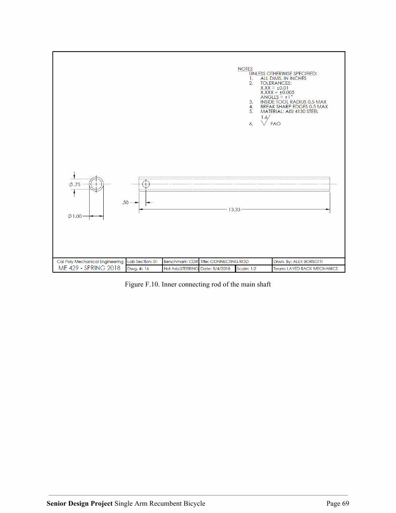
Figure F.10. Inner connecting rod of the main shaft
Senior Design Project Single Arm Recumbent Bicycle Page 69

Figure F.11. Back connector rod for connecting the main shaft sleeve to the central rear T-joint
Senior Design Project Single Arm Recumbent Bicycle Page 70

Figure F.12. Prototype Lean to Steer Bill of Materials
Senior Design Project Single Arm Recumbent Bicycle Page 71

Appendix G: Complete Drawings Package (Steering Lock)
Figure G.1. Top portion of the rotor mount in the final design.
Senior Design Project Single Arm Recumbent Bicycle Page 72

Figure G.2. Bottom portion of the rotor mount in the final design.
Senior Design Project Single Arm Recumbent Bicycle Page 73

Figure G.3. Caliper mount in the final design. The bottom portion of the ⌀1.380 hole is cut away to create
the arc which fits on the bike frame.
Senior Design Project Single Arm Recumbent Bicycle Page 74

Appendix H: CDR Purchased Parts Details Braking System:
1. Shimano XT 8020 Hydraulic Four Piston Brake: a. https://www.artscyclery.com/Shimano_XT_M8020_Four_Piston_Pre-
Bled_Disc_Brake_Rear/descpage-SHM802DR.html 2. Shimano RT86 XT Ice-Tech Brake Rotors:
a. https://www.artscyclery.com/Shimano_RT86_XT_Ice-Tech_Rotor_6-Bolt_203mm_/descpage-SHRT86203.html
Shifting System:
1. Shimano XT M8000 1x11 Shift Lever: a. https://www.artscyclery.com/Shimano_XT_M8000_Shift_Lever_Rig
ht_11_Speed/descpage-SHM8000RAP.html 2. Shimano XT M8000 GS Derailleur:
a. https://www.artscyclery.com/Shimano_XT_M8000_GS_Rear_Derailleur_11-SPD/descpage-SHRDM8000GS.html
3. Shimano M8000 1x11 Cassette, 11-46: a. https://www.artscyclery.com/Shimano_XT_M8000_11_Speed_Casset
te/descpage-SHICSM8.html 4. Shimano XTR Dura Ace Chain:
a. https://www.artscyclery.com/Shimano_Dura_Ace_XTR_HG901_11_Speed_Chain/descpage-SHHG9001.html
Steering System:
1. Single U-Joint, 1’’ OD: a. https://www.mcmaster.com/#6443k75/=1cp82rp
Senior Design Project Single Arm Recumbent Bicycle Page 75

Appendix I: Budget/Procurement List Budget: QL+ has graciously provided a budget of $6000 in order to complete this project. This budget will cover the cost of purchasing materials, manufacturing parts, completing the prototype, and building the final assembly. Vendors: All our parts, manufactured and purchased, will come for a variety of vendors. We will purchase all of our shifting and braking parts from Art’s Cyclery, a local bicycle component vendor based out of San Luis Obispo California. We will use this company because they are local and they will allow us to return parts that might not fit our design or get new parts easily. We will purchase raw materials for steering components from McMaster Carr. We will use this company because of their large range of part selection and their fast shipping. Purchasing Details: All of our parts will be purchased with a QL+ credit card. This purchasing method will allow us to not have to fill out any reimbursement forms and will allow QL+ to better keep track of the spending/expenditures.
Senior Design Project Single Arm Recumbent Bicycle Page 76

Appendix J: Analysis and Testing Details
Figure I.1. FEA of rear bracket (Lean to Steer)
Test: Apply 150 lb-in of torque to the pivot point, apply 10 lbs of downward force on lower bracket to simulate the weight load from the assembly, and fix the bracket at all fastening and weld points. Results: A Factor of Safety of 3.6 was calculated when comparing the yield strength of AISI 4130 steel to the recorded Von Mises stress. Conclusions: This indicates that the current design should be able to withstand the forces expected to put through it. If the bracket were to not function as expected and fail in testing, increasing the wall thickness from 1/8 in to 1/4 in would be able to increase the structural strength to acceptable levels.
Senior Design Project Single Arm Recumbent Bicycle Page 77

Figure I.2. Dampener Test
The figure above shows a test we performed on the rubber damper in this bike assembly. We tested the existing rubber bushing, and two new bushings made of neoprene rubber and natural rubber. The bushing that held the bike the strongest was selected since that will help dampen the unwanted steering effects of the user cranking input.
Table I.1. Results of rubber damper test
Damping Mount Type Average Resistive Force (lbf)
Old Damping Mount 7.0
New Neoprene Rubber 10.2
New Natural Rubber 11.5
Senior Design Project Single Arm Recumbent Bicycle Page 78

Figure I.3. Preliminary Strength Analysis of the Caliper Mount
The figure above shows analysis of the required force to negate the steering effects of the largest cranking force we expect the user to ever need to apply. The test pictured in Figure I.4 confirmed our design would hold strong.
Senior Design Project Single Arm Recumbent Bicycle Page 79

Figure I.4. Load Input Steering Test
Test: This test had the steering lock lever fully depressed with a load of 40 lbs applied to the center of the crank perpendicular to the crank action. The load was applied three times. Results: There was no slippage of the steering lock during the test. Conclusion: The steering lock successfully passed the test for ensuring the lock would not slip under the maximum expected circumstances for normal riding.
Senior Design Project Single Arm Recumbent Bicycle Page 80

Appendix K: Safety Hazard Checklist
DESIGN HAZARD CHECKLIST Team: Single Arm Recumbent Bicycle Advisor: Brian Self Date: 03/08/18 Y N
N 1. Will the system include hazardous revolving, running, rolling, or mixing actions?
N 2. Will the system include hazardous reciprocating, shearing, punching, pressing, squeezing, drawing, or cutting actions?
N 3. Will any part of the design undergo high accelerations/decelerations?
N 4. Will the system have any large (>5 kg) moving masses or large (>250 N) forces?
N 5. Could the system produce a projectile?
Y 6. Could the system fall (due to gravity), creating injury?
N 7. Will a user be exposed to overhanging weights as part of the design?
Y 8. Will the system have any burrs, sharp edges, shear points, or pinch points?
N 9. Will any part of the electrical systems not be grounded?
N 10. Will there be any large batteries (over 30 V)?
N 11. Will there be any exposed electrical connections in the system (over 40 V)?
N 12. Will there be any stored energy in the system such as flywheels, hanging weights or pressurized fluids/gases?
N 13. Will there be any explosive or flammable liquids, gases, or small particle fuel as part of the system?
N 14. Will the user be required to exert any abnormal effort or experience any abnormal physical posture during the use of the design?
N 15. Will there be any materials known to be hazardous to humans involved in either the design or its manufacturing?
N 16. Could the system generate high levels (>90 dBA) of noise?
Y 17. Will the device/system be exposed to extreme environmental conditions such as fog, humidity, or cold/high temperatures, during normal use?
Y 18. Is it possible for the system to be used in an unsafe manner?
N 19. For powered systems, is there an emergency stop button?
Y 20. Will there be any other potential hazards not listed above? If yes, please explain on reverse.
Senior Design Project Single Arm Recumbent Bicycle Page 81

Description of Hazard Planned Corrective Action Planned Date
Actual Date
Lack of control over recumbent bicycle.
Adding steering amplification? Refining idea more. Corrected: Our design created our connections/fasteners as strong as possible. This helped mitigate this issue.
CDR Post CDR
Bar coming straight at his chest
Maybe use a V shape. Corrected: By moving our steering design to the back of the frame, we prevented the bar from coming straight at Nick’s chest.
CDR Post CDR
Road hazards
Ensure responsive controls. Add reflectors.
Post CDR Post CDR
Senior Design Project Single Arm Recumbent Bicycle Page 82

Appendix L: Gantt Chart
Senior Design Project Single Arm Recumbent Bicycle Page 83

Appendix M: Manuals 2012 Intrepid Tourer Adult Handcycle:
Senior Design Project Single Arm Recumbent Bicycle Page 84

Appendix N: Ideation List Cranking
● Centered 1-piece crank ● Rowing mechanism ● In-out mechanism ● Spinning mechanism ● Pushing rail mechanism ● Crank at waist ● Shake weight design ● Pulling rope ● Open wheel push/pull spokes
Braking ● One hand brake for front and rear caliper ● Current braking with one brake for front ● Coaster brake ● Reverse direction of crank ● Hand brake on side of seat ● Handle twist brake ● Handle pull brake ● Button-initiated braking
Comfort ● Change angle of chair ● Place suspension on frame ● Change grips on bike ● Place handle directly in front of Nick ● Place handle lower to Nicks side ● Adjustable/lockable shocks ● Material of seat
Shifting ● 2 levers side-by-side ● Twist dial, rotating shifting ● Button initiated braking ● Directional braking ● Lever initiated braking ● Sliding gear selector from thumb ● Rolling shifter
Senior Design Project Single Arm Recumbent Bicycle Page 85
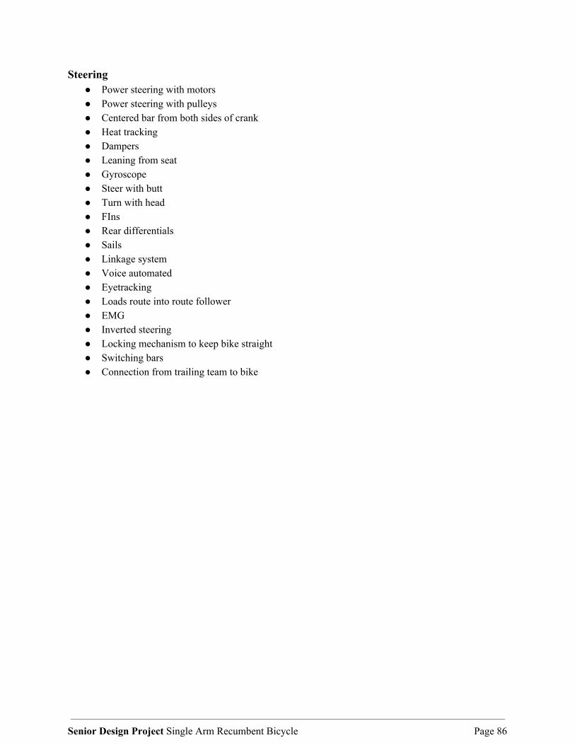
Steering ● Power steering with motors ● Power steering with pulleys ● Centered bar from both sides of crank ● Heat tracking ● Dampers ● Leaning from seat ● Gyroscope ● Steer with butt ● Turn with head ● FIns ● Rear differentials ● Sails ● Linkage system ● Voice automated ● Eyetracking ● Loads route into route follower ● EMG ● Inverted steering ● Locking mechanism to keep bike straight ● Switching bars ● Connection from trailing team to bike
Senior Design Project Single Arm Recumbent Bicycle Page 86

Appendix O: Finalized Bill of Materials
Table O.1 Finalized steering system bill of materials Part Name Specifications Part Number Manufacturer Cost
Aluminum Stock 6061, 1.5" thick, 4" wide, 6" long 8975K257 McMaster Carr $36.36
Aluminum Stock 6061, 2.5" thick, 2.5" wide, 6" long 9008K57 McMaster Carr $32.75
Brake Shimano SLX Brake M7000, rear long cable NA Shimano $89.24
Brake Rotor Shimano RT66 SLX, 6-Bolt rotor, 160mm NA Shimano $16.14
Clearweld Attachment to frame, 4400 psi JB Weld $4.47
Hose Clamp Attachment to frame, 1.75" in. SS $1.96
Metric Hex Nuts 2, M6 Hex Nut Home Depot $1.35
Grip Tape Blue standard road tape Cinelli $13.95
Total $196.22
Table O.2 Finalized braking system bill of materials
Part Name Specifications Part Number Manufacturer Cost
Brake Shimano SLX M7000, rear Shimano $102.29
Brake Rotor Shimano Ice-Tech Rotor, 203mm Shimano $27.89
Total $130.18
Senior Design Project Single Arm Recumbent Bicycle Page 87

Table 0.3 Finalized shifting system bill of materials Part Name Specifications Part Number Manufacturer Cost
Chain CN Chain Shimano $27.89
Shifter Di2 Shifter XT Shimano $292.94
Switch Di2 Electronic Switch Shimano $102.29
Attachment Topeak Wire Attachment Topeak $9.25
Lower Shifter Wire Electronic Di2 Shifter Wire Shimano $35.32
Upper Shifter Wire Electronic Di2 Shifter Wire, 2 Total Shimano $26.03
Monitor Device Electronic Di2 Monitor for Battery Shimano $21.38
Cassette Sunrace Cassette Sunrace $111.59
Battery Electronic Di2 Battery Shimano $88.34
Battery Mount and Wiring
Di2 Battery Mount, Charger, Wiring Shimano $111.59
Chainring Narrow-Wide, 32T Raceface $41.84
Derailleur Adapter Wolf Tooth $25.99
Total $894.45
Senior Design Project Single Arm Recumbent Bicycle Page 88

Appendix P: User Manual with Safety Guides This user’s manual is meant to be a guide to understand the functionality of this specialized product to be able to operate it in a safe and responsible manner. Refer to the official Intrepid Tourer Owner’s Manual for information about operating the bike itself. P.I. Propelling the Bike The recumbent bicycle is powered using a single aluminum hand crank located above the center of the body. The bicycle is powered by pushing the crank in a clockwise rotation. When this happens, the chain rotates over the cassette and pushes the wheel forward. Be aware of the location of your brake and shifter lever in front of you, and always ride so that you can engage the brakes quickly in case you need to stop.
Figure P.1. Hand crank location indicated by arrow
Caution:
Pinch Hazard - Keep hands clear of all moving parts when in motion. Chain, gears, and brakes all constitute pinch hazards.
Senior Design Project Single Arm Recumbent Bicycle Page 89

P.II. Shifting The shifter attached to the crank handle operates the derailleur at the wheel axle. Press the button labeled UP, as seen located below in Figure P.2, while pedaling to change to a lower gear ratio (making it harder to pedal). Pressing the button labeled DOWN in the figure below while pedaling will change to a higher gear ratio (making it easier to pedal). It might be necessary to shift to an easier gear in anticipation of a change in gradient of the riding surface. This way the risk of stalling on an incline is minimized. Be sure to rotate the crank when carrying out any switch operations which are related to gear shifting. By doing so, the chain will not drop and the derailleur won’t have to extend far over the cassette.
Figure P.2. Location of shifter buttons Figure P.3. Electronic information display
Table P.1. Shifter Assembly Part List
Shimano XT M8070 Front Derailleur Shimano SLX M7000 Hydraulic Disc Brake
Caliper
Shimano XT M8050 DI2 Shadow RD Plus Rear Derailleur
Shimano DI2 SHRT
11 Speed Cassette CSMX80 SM-BTR1 (Battery)
Shimano SC-MT800 (Information Display) SM-BCR1 (Battery Charger)
Senior Design Project Single Arm Recumbent Bicycle Page 90

Caution:
Pinch Hazard - When the shifting switch is operated, the motor which drives the front derailleur will operate to the shifting position without stopping, so be careful of finger placement. The components are designed to be fully waterproofed to withstand wet weather riding conditions; however, be careful not to let water get into the terminal. If water gets into any of the components, operating problems or rusting may result.
P.III. Steering Lock The purpose of the steering lock is to isolate the actions of steering and pedaling to avoid unwanted steering input from the user while cranking. The bike’s steering lock remains disengaged without user input. To engage the steering lock, apply pressure to the secondary steering brake lever - highlighted in the Figure P.4 below - to activate the steering lock.
Figure P.4. Steering lock lever Figure P.5. Steering lock caliper & rotor assembly
The steering caliper located in Figure P.5 will apply friction to the rotor according to user input. This grants the user the ability to apply variable resistance to the desired level of steering friction. Fully engage the steering lock by firmly depressing brake lever completely to secure steering in its current position. If the brake lever for the steering lock has slow response, the rotor rubs, the lever has unusual pull, or the system feels different, bring the bicycle to the nearest shop for repair or maintenance.
Senior Design Project Single Arm Recumbent Bicycle Page 91

Caution:
Do not operate bike if steering lock rotor cover is damaged or missing. Ensure steering lock is fully disengaged when suddenly maneuvering bike and/or making sharp turns. Sharp Edge Hazard - Shift brake mechanism has sharp edges, keep hands clear. Pinch Hazard - Keep hands clear of all moving parts when in motion. Chain, gears, and brakes all constitute pinch hazards.
P.IV. Braking Assembly The bicycle is slowed down and stopped using a disc brake assembly place on the left side of the front wheel. The brake lever for this disc brake assembly is located on the top of the handle shown in Figure P.4. When the user needs to slow the bike, he simply pulls the brake lever located on the hand crank which in turn compresses the caliper and slows the rotation of the rotor and wheel. The lever is located in close proximity to the user’s hand to ensure easy access and quick use of the brake lever. If the user experiences any issues with the brake assembly such as, but not limited to slow brake response, rotor rubbing, and unusual brake pull, bring the bicycle to your nearest shop for repair and maintenance. Caution:
Sharp Edge Hazard - Rotors and gears have sharp edges, keep hands clear. Pinch Hazard - Keep hands clear of all moving parts when in motion. Chain, gears, and brakes all constitute pinch hazards.
P.V. Maintenance Since our design consists of upgrading and adapting a recumbent bicycle, we will naturally have steady maintenance that must be performed in order to ensure high quality bicycle performance. All of the parts that will need maintenance are standard bicycle parts, able to be serviced by all local bike shops. The first sub-assembly on the bicycle which will require maintenance will be the electronic shifting. Since the shifting requires sophisticated wiring and batteries to operate, proper care and maintenance is priority. The battery for the electronic shifting will need to be charged every 100 rides. The electronic shift display has a battery level indicator at the top of the screen to allow for easy monitoring of the battery life. The battery charging time is approximately 1.5 hours. If any Shimano parts are broken or require replacement,
Senior Design Project Single Arm Recumbent Bicycle Page 92

Shimano offers a warranty. In these instances, the user will need to go through their local bike shop for ordering new parts and reinstallation. Also, the user can consult the Shimano website and follow the listed instructions for diagnosing the issue or proceeding with a warranty claim. The second sub-assembly which will need proper maintenance will be the steering lock. The system is composed of a brake rotor, caliper, and brake cables. Just like a typical braking system, the maintenance will consist of rotor alignment, brake bleeding, and brake lever adjustments. All of these tasks can be performed at a local bike shop. In addition, the system is composed of a caliper and rotor mount. If any of these parts seem to move unnaturally or wobble, check the bolts and tighten them will a standard torx or allen wrench. Lastly, if the user notices the rotor moving inside the caliper with high levels of force feel free to adjust the brake lever using the small knob. This small knob allows the user to adjust the lever position in relationship to the hand and increase the brake lever strength. If any of these issues continue, please consult the nearest bike shop for assistance. The final sub-assembly that will need maintenance will be the standard braking system. The system is composed of a disc brake system. Just like the steering lock system, it will need rotor alignment, brake bleeding, and brake lever adjustments. All of this maintenance can be performed at a local bicycle shop. General Warnings:
Pinch Hazard - Keep hands clear of all moving parts when in motion. Chain, gears, and brakes all constitute pinch hazards.
Sharp Edge Hazard - Rotors, gears, and the shift brake mechanism all have sharp edges, keep hands clear of these. Ensure the user is familiar with the bike’s control layout. Pay particular attention to the proximity of steering lock lever to the brake lever. Do not try to corner at high speeds as this could result in a fall causing injury or damage to the handcycle.
Senior Design Project Single Arm Recumbent Bicycle Page 93