since 1982 maritime fall 2017 engineering journal · the editor, maritime engineering journal,...
TRANSCRIPT

NationalDefence
Défensenationale
Maritime Engineering Journal Celebrates Canada 150
Fall 2017
A Rare Propulsion Gearing Incident
Feature Article
85Since 1982
CNTHA News
Inside!
Maritime Engineering JournalCanada’s Naval Technical Forum

see page 20
DGMEPM Mentorship Program
Retired RAdm Bill Christie (centre) was only 98 years old when he appeared as a guest of honour presenter for the DGMEPM mentorship event on Innovation
on June 19, along with co-presenters RAdm (ret.) Eldon Healey (centre left) and Captain (ret.) Jim Carruthers (centre right). He has since turned 99. All three
offered interesting naval historical perspectives with modern relevance.

Director General Maritime Equipment Program Management
Commodore Simon Page, OMM, CD
Senior EditorCapt(N) Christopher EarlChief of Staff MEPM
NCM Editorial AdvisorCPO1 Colin BrownDGMEPM Unit Chief
Project ManagerLt(N) Jotham Sterling
Production Editor/EnquiriesBrian McCullough [email protected]. (613) 831-4932
Associate Editor Tom Douglas
Graphic Design and Production Services d2k Graphic Design & Web www.d2k.ca Tel. (819) 771-5710
The Maritime Engineering Journal (ISSN 0713-0058) is an unofficial publication of the Canadian Armed Forces published by the Director General Maritime Equipment Program Management. Views expressed are those of the writers and do not necessarily reflect official opinion or policy. Mail and requests for free subscriptions may be sent to: The Editor, Maritime Engineering Journal, DGMEPM, NDHQ, 101 Colonel By Drive, Ottawa, Ontario, Canada, K1A 0K2. Unless otherwise stated, Journal articles may be reprinted with proper credit. A courtesy copy of the reprinted article would be appreciated.
Current and past issues of the Journal are available online at the website of the Canadian Naval Technical History Association – www.cntha.ca
(Established 1982) Fall 2017
85
Maritime Engineering Journal
Photo courtesy FMF Cape ScottClose-up of a crack in HMCS Montréal 's dye-painted idler gear tooth.
EditorialCommodore’s Corner by Commodore Simon Page, OMM, CD .....................................................................................................2
ForumTechnical Service Paper: A Proposal to Improve the Manual Bypass Louvres on the Gas Turbine Intake and Exhaust System in Halifax-Class Ships by MS Michael Stainton ........................................................................................................................ 4
Feature ArticlesA rare propulsion gearing incident and a successful team effort by Pierre Boucher and Claude Tremblay ......................................................................................................7End of an Era: The RCN Pays Off HMCS Athabaskan by LCdr Dominic Dupuis and Lt(N) André Filliol ................................................................................ 12NETE Celebrates 25 Years of Support Through the Mk-48/56 GMVLS In-Service Engineering Agency by Sébastien Barrette, Edward Sorensen and Jim MacAlpine .............................................................. 14
Book ReviewBearing Witness reviewed by Tom Douglas .....................................................................................17
News BriefsMaritime Museum of the Atlantic Marks the 100th Anniversary of the Halifax Explosion ....18SNAME New England Graduate Paper Award for RCN’s LCdr Ben Thomson et. al. ........19École de Guerre: Best foreign student geopolitical mémoire – LCdr Jonathan Lafontaine ...19DGMEPM Mentorship Program Event ........................................................................................20Commander RCN Town Hall Meeting with MEPM Team ......................................................21
CNTHA News The Short Life of the Electrical Branch .........................................................................................23Oral History Program – Excerpt from Bruce Wilson Interview by Colin Brown ................24

MARITIME ENGINEERING JOURNAL NO. 85 – FALL 2017
Maritime Engineering Journal 2 Celebrates Canada 150
W hile the Royal Canadian Navy (RCN) continues its recapitalization and advance-ment toward a “One Navy” model, a signifi-
cant number of changes are still necessary. In a few areas, we find ourselves at crucial junctions where many elements requiring examination intersect with one another – generating unique opportunities to make necessary change while also creating something different, innovative, and, to a certain extent, transformative.
At one such junction, in our area of naval engineering and naval technical responsibility, we face a series of intersecting vectors associated with the arrival of the RCN’s new platforms, including:
• the upcoming introduction of the new surface combatant; • the continuous influx of new technology within all
classes of vessels;• the evolution of the Reserve Force into a strategic force
with a focus on augmenting the Regular Force;• innovative advancement in the field of training and
education; and• a warranted examination of crew size for most ships.
These undoubtedly offer a singular opportunity to take a detailed look at some of the building blocks of the RCN as an institution – one of which is the raw composition of its occupations. The RCN’s 2013-2017 Executive Plan mandated the review of all naval occupations, beginning with those identified as requirements for future platforms. Although the new Weapons Engineering occupation paved the way for transformation in the late 2000s, the momen-tum of the vectors mentioned above made it imperative that the first occupation to undergo the latest general occupation review should be the Marine Technician.
From a technology angle, the installation of a diesel-electric 4.5-MW propulsion system aboard the Harry DeWolf-class Arctic and Offshore Patrol Ships (AOPS) was a key factor in resolving the long-lasting discussion regarding
By Commodore Simon Page, OMM, CD Director General Maritime Equipment Program Management
whether to combine the Electrical Technician occupation with the updated Marine Technician occupation. It had to happen. The introduction of new fleet technology, this time combined with the similarity of some tasks, skills and training, also precipitated the inclusion of the Hull Technician occupation within the scope of the new structure. Furthermore, the One Navy concept, at the heart of the manning strategy for the AOPS and Maritime Coastal Defence Vessels (MCDVs), provoked much-needed dialogue on integrating the Reserve Marine Engineering System Operator (MESO) occupation under the umbrella of the new occupation. New crewing concepts, optimization in watchkeeping, and innovation in personnel qualification represented the last elements of the transformation structure, and after a commendable and considerable amount of work the new Marine Technician occupation was stood up on May 1, 2017.
When speaking about the creation and implementation of the Marine Technician occupation in the past, I have always focused on two elements: The first is that our occupations must remain technically able to continue providing preventive and corrective maintenance for all RCN platforms – combatants, and non-combatants. Our technicians must be able to effectively conduct repairs across a large spectrum of systems and equipment within a wide variety of scenarios so that commanding officers at sea can rely on such skills and the inherent technical flexibility in all missions. This has been the foundation of our technical occupations in the past, and it must prevail into the future. The second element is that the qualification process for all naval technicians must remain well-estab-lished and sound. From the standpoint of training assur-ance and personnel regulation within the larger naval materiel management system, it is imperative that we continue to qualify personnel diligently because the responsibilities for operating and maintaining our machin-ery plants certainly have not diminished in any way.
A new RCN Marine Technician occupation for a One Navy future
COMMODORE'S CORNER

MARITIME ENGINEERING JOURNAL NO. 85 – FALL 2017
Maritime Engineering Journal 3 Celebrates Canada 150
I am confident that we have created a model that will become the envy of navies around the world. The widely recognized quality of our engineering-technical knowledge and expertise will not only be preserved, but will result in a more resilient and integrated workforce. Finally, the design of the new Marine Technician occupation will ensure that all young sailors have meaningful careers filled with professional challenges and excellent advancement opportunities – something that the new occupation
pyramid promotes admirably. There is no doubt that bold and energetic leadership will be required throughout the entire RCN, as change of this order is always challenging to effect, but without such struggles we will rarely see progress.
C apt(N) Christopher Earl has come aboard as the new Senior Editor of this publication. He replaces Capt(N) David Benoit who has
relocated to London, England for National Security Studies at the Royal College of Defence Studies.
Capt(N) Earl joined the Canadian Forces in 1986 and has broad experience in leadership, naval project management, and materiel readiness support of ship and submarine operations.
After graduating from the Royal Military College and completing his formal training in various ships and shore establishments, Capt(N) Earl completed several operational tours in both the Oberon- and Victoria-class submarines. Shore duty included tours in the Canadian Forces Naval Engineering School, Naval Requirements, the Royal Navy submarine support organization, Project Manager for the Submarine Capability Life Extension project, Class Manager for the Victoria-class submarines, and Director of Maritime Equipment Program Management (Submarines).
Capt(N) Earl holds a Bachelor’s degree in Electrical Engineering, a Master’s degree in Defence Studies, and is a graduate of the Canadian Forces College Joint Command and Staff Program, and the National Security Program.
Promoted to the rank of Captain (Navy) in 2013, he commanded Fleet Maintenance Facility Cape Breton in Esquimalt, BC for four years, and was appointed to his current assignment, Chief of Staff – Maritime Equipment
New Senior Editor takes the helm at the Maritime Engineering Journal
Program Management, in August 2017. Serving as Senior Editor of the Maritime Engineering Journal is part of this new mandate.

MARITIME ENGINEERING JOURNAL NO. 85 – FALL 2017
Maritime Engineering Journal 4 Celebrates Canada 150
The air intake mechanism for the gas-turbine (GT) engines in Halifax-class frigates is located in the forward engine room casing between the boat
decks. The intakes face aft to minimize ingress of sea spray in the air. The first line of protection for the intake air consists of two rows of large fixed louvres (Figure 1), each fitted with a wire mesh screen to block large foreign object debris (FOD). In the event these FOD screens and louvres become blocked and prevent proper air flow, the intake system is fitted with a lower row of small bypass louvres that must be opened manually by the use of “D” handled cables located forward of the Halon gas compartment. These louvres, however, do not always open as designed, due to corrosion of the hinges and the hinge pins.
Technical BackgroundThe purpose of the gas-turbine intake system is to provide an uninterrupted supply of clean, particle-free air for combustion, as well as providing ventilation/cooling air to the enclosure to reduce heat on the surface of the engines and the enclosure walls. After the air has been filtered through the intake system it is drawn into the compressor where it is compressed to a ratio of 16:1. Twenty per cent of this air is mixed with fuel for combustion. The other 80 percent is used for engine cooling, flame shaping, sump pressurization, thrust balancing, and anti-icing.
By MS Michael Stainton[Supporting references are contained in the author’s source document.]
CANADIAN FORCES NAVAL ENGINEERING SCHOOL HALIFAX –
A MAR ENG QL6 COURSE TECHNICAL SERVICE PAPER ADAPTATION
A Proposal to Improve the Manual Bypass Louvres on the Gas Turbine Intake and Exhaust System in Halifax-Class Ships
FORUM
In the eighth stage of the compressor, air is bled through the hollow stator vane tips into an external manifold where it goes to the forward and after ejector nozzles. Air from the forward ejector is used to cool and pressurize the A and B sumps of the gas turbine. The after ejector cools and pressurizes the C and D sumps. The ninth-stage bleed air is piped to the turbine mid-frame to cool the HP turbine after- face, the turbine mid-frame, and the power turbine. Air to
Editor’s note: The QL6 course technical service paper gives senior non-commissioned personnel an opportunity to develop their ability to study a technical problem, devise solutions, and present their findings. It is a valuable training project and no small challenge. The Journal is pleased to support this important initiative.
Figure 1. The gas-turbine air intakes on the upper deck of a Halifax-class frigate.

MARITIME ENGINEERING JOURNAL NO. 85 – FALL 2017
Maritime Engineering Journal 5 Celebrates Canada 150
the turbine rear frame combines with 13th stage bleed air to provide forward loading of the power turbine rotor. The 13th stage bleed air also cools the second-stage high-pressure turbine nozzles. The compressor discharge air is used for cooling the combustion liner and the first-stage rotor blades and nozzle vanes of the high-pressure turbine. The discharge air is also piped to the anti-icing manifold to prevent a buildup of ice which could result in engine failure if it were ingested into the system.
Since a disruption of air to the GTs could lead to cata-strophic engine failure, redundancies in the GT intake system ensure there is an uninterrupted supply of air for combustion and ventilation/cooling. If there is a pressure differential across the combustion air inlet filters exceeding 185-mm WG, the blow-in doors will automatically open and the GT will be supplied with unfiltered air at the inlet. If there is a differential pressure across the ventilation/cooling air inlet filters exceeding 75-mm WG, the blow-in doors for the enclosure cooling will automatically open, supplying unfiltered air to the enclosure. In the event that the louvres and FOD screen experience excessive blockage, the very last attempt to supply uninterrupted air flow to the GTs is done by manually opening the lower panel of louvres (Figure 2). When these are opened, the first line of removing moisture and debris is bypassed. However, the air is essential for cooling to enable efficient operation of the gas turbine.
The ProblemIn the event there is blockage in the louvres and the FOD screen, it is essential when the “D” handles on the bypass louvres are pulled that they will in fact open. On the majority of the Halifax-class ships significant force has to be used to
Figure 2. A manually operated air intake bypass louvre. Figure 3. A bypass louvre hinge and hinge pin seized through corrosion.
overcome the effects of corrosion on the steel hinges and hinge pins (Figure 3). The type of steel used is not the most suitable material for the environment and, with the lack of maintenance done on the bypass louvres, the resultant factor is a failure to open. The current material used for the hinge pin is austenite 304, and for the hinge is mild steel. Over time, the hinges and pins are subjected to so much corrosion and buildup of debris that they seize. Proper maintenance and lubrication only slows this process.
The proposed solution must provide smooth operation of the bypass louvres when the “D” handles are pulled. It must also be cost-effective, prevent – or vastly slow down – corrosion, and avert buildup of debris between the hinge and the hinge pin.
Options Analysis and RecommendationOption A involves having the Fleet Maintenance Facility (FMF) fabricate replacement hinges and pins (Figure 4) using a higher grade of stainless steel, preferably marine grade austenitic 316 series, which has an increased resis-tance to corrosion due to the content of chromium (18%) and nickel (10%). The amount and type of material required is shown in Table 1.
Option B involves the same fabrication as in Option A, but includes the addition of a Teflon sleeve on the hinge pin to prevent the buildup of debris. Teflon, of course, has an extremely low coefficient of friction, is strong and tough, and self-lubricates at low temperatures – thus negating the need for grease. The FMF would be used for fabricating the hinge plate, hinge pin, and the Teflon sleeve.

MARITIME ENGINEERING JOURNAL NO. 85 – FALL 2017
Maritime Engineering Journal 6 Celebrates Canada 150
Table 1. Replacement material specifications and costs.
Type (316) Size Amount Cost (Approx.)Plate 1.02m2, 3/8in thick 1 $118
Round Bar 25.4mm x 75mm 8 $216 (total)
Type (PTFE) Size Amount Cost (Approx.)Round Bar 25.4mm x 75mm 8 $42 (total)
Figure 4. Schematics of the hinge and hinge pin.
Both proposed options meet the criteria required to provide smooth operation of the manual bypass louvres on the GT intake system when the “D” handles are pulled. They both prevent or slow down the effects of corrosion, and guard against the buildup of debris between the hinge and hinge pin. They are also cost-effective, with materials not exceeding $400 for either option. Although Option B is slightly more expensive due to the inclusion of the Teflon sleeve, this is recommended as it best prevents buildup of debris, does not require grease for lubrication, and will cut down on maintenance.
An Unsatisfactory Condition Report (UCR) should be completed. Upon successful completion of the UCR, a proposal for an Engineering Change (EC) should be raised for the fabrication and installation of new hinges and hinge pins for the GT intake system on all Halifax-class ships.
MS Stainton is the Main Machinery Room 2/IC aboard HMCS Toronto.
AcknowledgementThe advice of technical advisor Petty Officer Second Class Phil Kelley is gratefully acknowledged.

MARITIME ENGINEERING JOURNAL NO. 85 – FALL 2017
Maritime Engineering Journal 7 Celebrates Canada 150
FEATURE ARTICLE
By Pierre Boucher and Claude Tremblay
A rare propulsion gearing incident and a successful team effort
A sk people what is the most essential part of a warship, and everyone has an opinion. In June 2016, a damaged gear tooth number 17 located on
the lower idler inside HMCS Montréal’s starboard gearbox made its own bid for that distinction. Considering the impact it had on the ship’s operations and the resources required to repair it, it was a claim with some merit. If it had completely detached itself from the gear and gone through adjacent teeth, it would have caused a catastrophic failure. Fortunately, it was discovered in time during a routine alongside inspection.
With assistance from marine technicians from Fleet Maintenance Facility Cape Scott (FMFCS), Formation Gearing Inspector Pierre Boucher visually inspected a representative sample of gear teeth on all rotating elements through the fitted inspection doors as required by the ship’s preventive maintenance routine. This inspection process included painting a number of gear teeth with dye so that the meshing pattern can be inspected after the ship has
operated at high power for a few days. The pattern would be determined by the location and amount of paint removed due to friction.
It was the keen eye of Hal Payne from FMF who noticed a blemish on the tooth before the dye was applied. The inspector immediately initiated a more detailed inspection using non-destructive testing methods such as liquid penetrant inspection (LPI) and magnetic particle inspection (MPI). A third option was attempted using ultrasonic testing (UT), but this proved ineffective due to the relatively small space between the gear teeth where the testing instrument could not be fitted. After sharing the findings with the original equipment manufacturer (OEM) Damen Schelde Gears of the Netherlands, it was decided to carefully monitor the defect during sea trials.
Figure 1 shows the crack following the sea trials with the painted gear. Figure 2 shows the crack during the liquid penetrant testing. Although the crack looks large, it could
Pho
tos
cour
tesy
FM
F C
ape
Sco
tt
Figure 1. Surface crack shown during initial gear inspection.

MARITIME ENGINEERING JOURNAL NO. 85 – FALL 2017
Maritime Engineering Journal 8 Celebrates Canada 150
be a shallow surface defect made by a foreign object going through the gears. The LPI did not reveal a deeper crack on the initial test probably because the crack had filled with oil during operation, leaving no room for the dye to penetrate. As subsequent LPIs were performed, and more oil was removed so that more dye could fill in, a deeper defect was revealed.
Upon the ship’s return the defect was further inspected, this time using a more sophisticated method being evaluated by Defence Research and Development Canada – an alternating current field measurement (ACFM) process that provides a view of the interior of the tooth. It revealed the presence of two defective regions, one large crack of roughly 100 mm in length on the tooth’s flank, and a similar surface breaking crack near the tooth root on the opposite flank of the affected tooth. The ACFM technique allows a measure-ment of the depth of the crack, which in the case of the main crack was estimated to be between 10 and 16 mm deep. Figures 3 and 4 show the results of the ACFM inspections in a normal gear and the cracked gear, respectively. There was no doubt that this gear would need to be replaced.
This could not come at a worse moment for HMCS Montréal. She was about to be deployed for the annual Great Lakes tour, and because of her unique flight-deck and hangar configuration was committed to support the trials for the new Cyclone helicopter project, which included chasing storms and heavy seas to test the flight-deck operations under extreme conditions. What this initially produced was a frenzy of meetings, briefings and risk assessments of all sorts. The frigates can operate with one shaft locked, but during single-shaft operation there are power restrictions and a reduction in ship manoeuvrability, especially in confined waterways such as the locks along the St. Lawrence Seaway. In this case, however, there was an addition-al difficulty that had to do with manufacturing a new gear.
After many years of operation, the gears inside a gearbox develop wear patterns that in effect create a unique, matched set of gearing elements. Because of that, an idler gear cannot simply be taken from another ship or manufac-tured from a standard drawing. The way the OEM was going to go around this was to use the damaged gear to provide a detailed, precisely measured profile in the OEM’s shop so that an exact copy could be made. This meant that the damaged gear (only one tooth had a crack, the rest was intact) had to be removed from the gearbox. Operating a ship with a locked shaft that has a missing gear requires careful consideration as the locking mechanism could be less effective
Figure 2. Surface crack shown by liquid penetrant testing.
Figure 3. ACFM inspection of a normal tooth.
Figure 4. ACFM inspection of the damaged tooth.

MARITIME ENGINEERING JOURNAL NO. 85 – FALL 2017
Maritime Engineering Journal 9 Celebrates Canada 150
in stopping the shaft from turning. Special precautions needed to be taken in the gearbox, and in the operation of the plant by the ship. Following exhaustive risk-analysis discussions, it was decided to proceed with the removal of the gear and allow the deployment of the ship for portions of the scheduled helicopter trials.
Ever since their manufacture in the early 1990s the gears in the frigates have produced minimal issues, so there was no need for a standing contractual agreement between the OEM and DND. Contracting can be a lengthy process involving more than one government department having conflicting priorities, but this incident demonstrated that when necessary the planets can be made to align. An initial contract was released within days to obtain the services of a field service representative (FSR) to remove the damaged gear, which was quickly followed by a second contract, through Public Services and Procurement Canada (PSPC) this time, for the manufacture of a new replacement gear.
The idler plays a special role inside the gearbox. Port and starboard shafts rotate in opposite directions, while the main engines, gas turbines and diesel all rotate in the same direction. It is through an idler gear that the direction of rotation is changed on the starboard side. An idler gear is simply an extra gear installed in one of the gear trains to reverse the rotational direction of that shaft. Because of its function the idler both is driven by the primary pinion, and drives the primary gearwheel; in other words, it is meshed between two other gears.
A picture of a gearbox with the cover removed is shown at Figure 5. There are two sets of idlers, a dual-tandem arrangement that distributes the power through two sets of gears allowing them to be smaller so that the gearbox can be made more compact. From its position between the primary pinion and lower primary gearwheel, the idler cannot be simply lifted out of the mesh. For the idler to be removed, one of the two adjacent gears has to be free-turn-
Figure 5. Starboard gearbox.

MARITIME ENGINEERING JOURNAL NO. 85 – FALL 2017
Maritime Engineering Journal 10 Celebrates Canada 150
ing; the lower gearwheel has to be separated from its own shaft. The lower gearwheel is assembled in a quill shaft configuration where the surface gear wheel is a separate assembly coupled to the central shaft so that it can be rotated independently when unbolted. To add to the complexity of the arrangement, the whole dual-tandem gear train is locked. This means that a slight rotational load is applied to the gears when assembled to remove any backlash (looseness) in the ahead direction, thus ensuring an even distribution of the rotating load throughout the gear train. By separating the quill shaft, the pre-load would be released. Through the combined resourcefulness and ingenuity of the FSR and the FMFCS technicians, this delicate process was uneventful. Once removed (Figure 6), the idler was packaged and shipped immediately to the Netherlands.
While waiting for the delivery of the new gear, the ship was configured to operate safely for sea trials that could be performed on a single shaft. With a missing gear, the locked train feature is lost and backlash is introduced into the mating gears, which presents some concerns over fretting. To prevent any axial motion of the gearwheel, special braking locks were installed by the FSR on the lower primary gearwheel (Figure 7). The missing idler gear also had an impact on the associated empty journal bearings, so dummy journal shafts were installed in the bearings to regulate the flow of oil. With these precautions in place, the gearbox covers were reinstalled and the ship sailed. To keep the engineering staff on their toes, operating with a locked
shaft produces a number of unusual noises and bangs which required many discussions aboard ship and with engineers ashore.
The manufacturing of the new gear went as planned. Fortunately, the OEM had a raw forging available for a gear of the appropriate size. Besides machining the gear teeth to the proper profile, an important step was to surface-harden the steel to increase fatigue resistance and hardness. The surface could be either nitridized or carburized. The latter was done in the present gear due to the type of steel that was available. In this process the gear is placed in an oven for a specific period of time that cannot be accelerated or shortened. Special business arrangements were made by the manufacturer with their very busy subcontractor in Germany to process this gear on a priority basis.
Once again, the excellent cooperation between the DND procurement officer, Sylvie Simard, and the contract-ing officer in PSPC, Robert Burns, produced a third contract to provide two FSRs for the installation and testing of the new gear. To make things more stressful, the rapidly approaching Christmas holiday season threatened to reduce the availability of the ship for the final installation which would require sea trials. Could this be done before the crew’s leave period?
Some delays in the transportation of the new gear from the Netherlands to Halifax increased the tension all around. Upon its arrival on a cold Sunday morning, the gear was quickly absorbed by the ship and the installation commenced.
Figure 6. Idler gear being rolled out of the gearbox. Figure 7. Gearwheel fitted with temporary brakes (white plastic).

MARITIME ENGINEERING JOURNAL NO. 85 – FALL 2017
Maritime Engineering Journal 11 Celebrates Canada 150
The locking devices were removed, the gearwheel freed once again, and the new idler gear was lowered into place and rotated into mesh with the primary pinion. Particular attention was taken to maintain the original relative position of all gearing elements to keep the original timing of the gear train (Figure 8). Once in position, the idler was fitted with new bearings and the pre-load was adjusted into the gear train by lightly loading the lower primary gearwheel. Marking dye was applied to the gear teeth, and the assembly was rotated to verify the meshing.
The team of the two FSRs, the FMF inspector and technicians, and ship’s staff achieved a proper holiday miracle – the gearbox was all buttoned up and ready for sea trials by the end of the last week before the start of the leave period. HMCS Montréal proceeded to sea with the gearing experts on board to monitor the progress. The meshing was carefully checked at every step from assembly, to basin trials and sea trials, and was found to be correct.
Four months after discovering the deep crack, the gear had been replaced and all ship’s operating restrictions were lifted. Following the holidays, HMCS Montréal proceeded with the planned storm-chasing operations for the new helicopter trials with minimal delay.
As for gear tooth number 17, its defeat was complete. It was dissected in a specialized laboratory in Munich to determine the root cause of the crack. This information,
Figure 8. Idler gear being installed in the gearbox.
when available, will be shared with gear manufacturers throughout the world to further improve the engineering knowledge of gear manufacturing and the gear limitations. Fortunately, this type of failure is extremely unusual, and the lessons learned from this incident should make such events even rarer. A rigorous inspection plan is being imple-mented throughout the fleet to catch any other gear teeth attempting to make their own claims of importance.
Without minimizing the technical accomplishments during this event, the most impressive part might be the team cooperation demonstrated by all participants from different parts of the world, whether in Halifax, Gatineau, the Netherlands, Germany, or aboard ship on the high seas.
Pierre Boucher is an ex-MarEngArt and MSEO, and is now the Formation Gearing Inspector at Fleet Maintenance Facility Cape Scott.
Claude Tremblay is the Transmission Systems Engineer in the Directorate of Naval Platform Systems in Ottawa.

MARITIME ENGINEERING JOURNAL NO. 85 – FALL 2017
Maritime Engineering Journal 12 Celebrates Canada 150
FEATURE ARTICLE
By LCdr Dominic Dupuis and Lt (N) André Filliol
Paying-off HMCS Athabaskan – End of an Era
T he official paying-off on March 10, 2017 of HMCS Athabaskan (DDG-282) – the last of the “Sisters of the Space Age" – signalled the end of the
Iroquois-class (IRO) destroyers, sometimes referred to as the Tribal Class, but often simply as the “280s.” Our last port visit, to Bermuda, which was also where Athabaskan made her very first port visit after commissioning in 1972, had been filled with mixed emotions, ranging from the satisfaction of knowing that our mandate had been duly fulfilled, to sadness as we marked the end of the 280 era. The ship’s paying- off ceremony that followed at Dockyard Halifax will remain engraved in our memories forever. As Athabaskan slowly made the approach to her final berth on that crisp March afternoon we realized that, as the ship’s engineers, our efforts and those of our predecessors had kept the ship going strong for 45 years – right until the very end.
Athabaskan 282, third of name, was laid down on June 1, 1969 at Davie Shipbuilding in Lauzon, Québec, launched on November 27, 1970, and commissioned into the Royal Canadian Navy (RCN) on September 30, 1972. Following a mid-life refit during the Tribal Class Update and Modern-ization Project (TRUMP) on June 4, 1994, the ship’s classification changed from Destroyer Helicopter (DDH) to Destroyer Guided Missile (DDG).
Athabaskan participated in numerous missions during her service, most notably Operation Friction, Canada’s contribution to the Gulf War from 1990 to 1991. She also assisted with disaster relief efforts during Op Unison after the passage of Hurricane Katrina in Mississippi in 2005, and during Op Hestia following a 7.0 magnitude earth-quake in Haiti in 2010. In 2016, Athabaskan joined Exercise Trident Juncture, the largest NATO exercise of recent years, exposing the Alliance of Nation’s resolve and unity in response to the Russian invasion of Ukraine. Following her final refit in 2012, Athabaskan was assigned a training role and served the final few years of her commis-sion qualifying Sea King air crews, and providing sailors much-needed sea time during the final years of the Halifax-Class Modernization project.
Life on a soon-to-be-retired ship has its drawbacks as well as its benefits. While the pool of IRO-class experi-enced personnel had only one remaining ship where they could apply their knowledge and skills, the need to make do with what we had meant we had to find innovative solutions to overcome any technical challenges. This will most certainly benefit the junior technicians as they move on to newer platforms. With training establishments discontinued for many of the ship-specific systems, and with the lack of certain equipment, it was left to the supervisors and senior technicians on board to teach the junior personnel how to maintain the ship’s technical readiness while maintaining their perishable skills. It was up to us to keep our technicians, operators, and trainees motivated, and with a bit of creativity and constant buy-in from a great bunch of individuals our departments were able to pull through.
As Athabaskan would be the third vessel to retire in recent years from the East Coast, we studied the well-docu-mented paying-off and divestment programs of Iroquois (DDG-280) and Preserver (AOR-510) to create a strong foundation for the plan we would execute ourselves. We were fortunate to count several of those ships’ paying-off and divestment crew among our own ship’s company, so were able to incorporate any lessons they had learned.
HMCS Athabaskan arriving at Lisbon, Portugal during Exercise Trident Juncture – Jointex ‘15 on October 18, 2015.
Pho
to c
ourt
esy
RC
N

MARITIME ENGINEERING JOURNAL NO. 85 – FALL 2017
Maritime Engineering Journal 13 Celebrates Canada 150
In December 2016 the Athabaskan divestment planning team met with the representatives from the DGMEPM Minor War Vessels and Auxiliaries (MWVA) section who would be overseeing the final disposal of the ship. With the paying-off ceremony set for March 10, 2017, our team had to determine what the ship’s program would look like from then until a yet-to-be-determined disposal date in the summer of 2018.
From the early going of our planning process it was made clear to us that our request for a care and custody crew would need to be carefully justified since the person-nel coordination centres and career managers were eager to get their hands on our crew to fill empty billets elsewhere. Like Iroquois and Preserver before us, our analysis indicated that 23 personnel would be a feasible number for steady-state care and custody crew manning – as long as there was no need for us to maintain a seven-person 24/7 duty watch as dictated by Ship’s Standing Orders (SSOs).
As the ship would belong to MARLANT until the transfer to ADM(Mat) a week prior to disposal, approval to modify our duty watch structure, and to remove selected emergency systems such as small boats in case of a man overboard in harbour, rested with Commander of Canadian Fleet Atlantic (CCFL). In order to get approval, a Hazard Identification and Risk Assessment (HIRA) – as outlined in the Naval Materiel Risk Management Canadian Forces Technical Order – would be needed to identify and analyze the risks involved in our proposed divestment plan. Shortly after starting to draft the HIRA we realized that another document would need to be produced that would be read alongside our HIRA: the Care and Custody Standing Operating Procedures (SOPs). Since we would be deviating from certain elements of SSOs by permanently shutting down systems, ceasing certain maintenance routines, and introducing new capabilities such as a portable generator on the jetty, our new operating construct needed to be formal-ized for all to see through new SOPs.
Once the draft HIRA and SOPs were complete, the next step was to engage key coastal stakeholders. The input from Fleet Technical Authority (Surface), Sea Training and the Preserver Care and Custody crew was invaluable in ensuring we had proper plans in place to mitigate the risks involved in leaving a former warship unmanned overnight and on weekends. Once we got the endorsement from these organizations, we submitted our documentation to CCFL.
In early June of 2017 our plan was approved, allowing Atha-baskan to fully enter the final phase of an illustrious career.
The Head of Department tour is by far the career highlight of all naval technical officers, and the two of us feel extremely fortunate to have had the opportunity to be the last two engineer officers to serve on board the mighty Athabaskan, last of her kind. The planning and execution of the divestment program was one of the larger challenges we faced, and one for which we had little to no experience, but the application of a problem-solving approach developed during previous tours aboard ship and in various shore postings saw us through. We will be forever grateful for the trust that was imparted to us to lead the two largest departments on board a ship many felt to be the best in the fleet – “Battleship Athabaskan,” as our former Cox’n CPO1 Shawn Coates referred to her.
In her final 18 months in commission, from September 2015 to March 2017, HMCS Athabaskan sailed the equiva-lent of nearly twice the circumference of the globe, con-sumed more than 11 million litres of fuel, fired 1569 rounds of 76-mm ammunition down range, conducted several operations and exercises, and showed the flag in many incredible ports. And what a ride it was. We had the pleasure of serving a great command team, and leading a fine group of technicians and junior officers through many challenges and obstacles. Together with our shipmates, we remained true to Athabaskan’s motto – We Fight as One, always.
LCdr Dominic Dupuis (CSEO) and Lt(N) André Filliol (MSEO) were HMCS Athabaskan’s paying-off engineering officers.
Athabaskan's paying-off pennant.
Pho
to b
y M
S C
ruz
Ale
gre,
and
LS
Kris
ten
Sol
tesz
, cou
rtes
y of
P
O1
Chr
isto
pher
Old
ham

MARITIME ENGINEERING JOURNAL NO. 85 – FALL 2017
Maritime Engineering Journal 14 Celebrates Canada 150
FEATURE ARTICLE
By Sébastien Barrette, Edward Sorensen and Jim MacAlpine
NETE Celebrates 25 Years of Support Through the Mk-48/56 GMVLS In-Service Engineering Agency
T he Royal Canadian Navy (RCN) has long depended on the Seasparrow missile for ship self-defence purposes, a missile system developed,
produced and supported by the NATO Seasparrow Project Consortium since 19681. Canada became a member of the Consortium in 1982 and has played a significant role ever since, providing both financial and human resources in support of evolving Seasparrow capabilities, but its greatest contribu-tion has perhaps been in the development of the Seasparrow vertical launch system. The RCN was the first navy to adopt the Mk-48 Guided Missile Vertical Launch System (Mk-48 GMVLS), which was procured under the Canadian Patrol Frigate (CPF) project. For the past 25 years, the Naval Engineering Test Establishment (NETE) through the Mk-48 GMVLS In-Service Engineering Agency (ISEA) in Halifax, Nova Scotia has been an important enabler to maintain the Seasparrow GMVLS capability.
Development of the Mk-48 GMVLSThe RCN has been involved with Seasparrow missile launching systems since the initial development of the DDH-280 program. The first successful firing of a Seasparrow missile from a Canadian ship took place in June 1974 from HMCS Athabaskan2. Variations of the Seasparrow missile served the tribal class well until it was ultimately replaced in 1994 by the US Navy (USN) Standard Missile under the Tribal Class Update and Modernization Project (TRUMP).
The RCN formally initiated its participation in the development of a vertically-launched Seasparrow capability in 1980. Until then, the sole Consortium-supported launcher was the USN’s Mk-29 eight-cell trainable Guided Missile Launch System (GMLS). Although a dependable system, it was deemed too heavy and bulky. The RCN was looking for a better fit for the CPF project. A successful firing of a vertically launched Seasparrow from HMCS Huron in 1983 proved that a vertical launch system, with its better
reliability, maintainability and reduced footprint and weight was a viable option for the new frigates. The Mk-48 GMVLS was developed by Raytheon under contract from Paramax Electronics Inc. of Montréal as part of the CPF project. It was formally adopted by the NATO Seasparrow Project Office (NSPO) as a Consortium product in 1983, and was first implemented by Canada and the Netherlands and shortly thereafter by Greece in 1988.3
Conception of the Mk-48 GMVLS ISEAWith 20 ships adopting the Mk-48 GMVLS it became apparent to the NSPO that an in-service engineering agency was needed to provide dedicated engineering and logistical support to the system. With the largest number of Mk-48 systems in service,
1. Cdr David MacDougall, Missile Engage! Canada’s 20 Years with the NATO SEASPARROW Project, Maritime Engineering Journal, Summer 2003, p. 82. Phil R. Munro, Project Mermaid: The Canadian Sea Sparrow Missile Program, Maritime Engineering Journal, June 19973. MacDougall, Missile Engage! Canada’s 20 Years with the NATO SEASPARROW Project, p. 10
First Canadian ESSM firing, HMCS St. John’s, November 2004.

MARITIME ENGINEERING JOURNAL NO. 85 – FALL 2017
Maritime Engineering Journal 15 Celebrates Canada 150
the RCN and DGMEPM realized the advantages of having the ISEA in Canada. Cdr Kenneth McLaren (Senior Staff Officer for new Equipment Trials), LCdr Rick Burnham (Canadian National Deputy at NSPO) and LCdr Wilf “Rogie” Vachon (DMCS-2 Project Officer Seasparrow) conceived the idea for the Canadian Mk-48 GMVLS ISEA while upgrading the
4. www.natoseasparrow.org5. News Briefs, Maritime Engineering Journal, June 1992, p.30
The original members of the ISEA (left to right): Frank Reinhardt, Shirley Fenton, Bruce Hartlen, Kenneth McLaren.
Mk-48 GMVLS ISEA and the RCNSince its inception in 1991 the Mk-48 GMVLS ISEA has been staffed by NETE personnel, and has had a close relationship with the RCN, the Fleet Maintenance Facilities, and DGMEPM staff. During the early nineties as the new frigates were accepted into the fleet, the ISEA proved to be a valuable asset to the RCN and DGMEPM, assisting with the resolution of various technical issues encountered that ultimately resulted in the successful integration of these new launch systems.
Following the rather dynamic period of the early to mid-1990s, the operation of the Mk-48 Mod 0 GMVLS stabilized for the RCN, and the program entered the in-service phase in its true sense. The ISEA provided a mixture of engineering support services including technical failure investigations, pre- and post-flight analyses, logistics support, configuration management support, and software evaluations, to name but a few activities. This relatively “quiet” period was short-lived. The Consortium nations soon recognized the need to improve the Seasparrow missile to meet the current and future threats, triggering the development of the Evolved Seasparrow Missile (ESSM). The Mk-48 GMVLS underwent design review and development phases to implement the necessary changes to properly support the new ESSM. Canada implemented the Mk-48 Mod 4 variant in 2004. For the next six years the ISEA provided the RCN with continuous engineering support while its ships underwent that conversion. The first successful firing of the new ESSM took place from HMCS St John’s in November 2004. Complete integration of the Mk-48 Mod 4 GMVLS finished in the fall of 2011 with the successful test firing by HMCS Regina.
Today the Mk-48/56 ISEA continues to build on its past history of providing in-service engineering support to the RCN and DGMEPM. Throughout the Halifax Class Modernization Program, the ISEA played a critical role in the development and testing of the uplink capability for the RCN. This recent improvement now allows ships to update the target state to the missile after launch. The ISEA also provided assistance in the integration of the Mk-48 Mod 4 GMVLS with the new CEROS fire-control system and the new Combat Management System (CMS).
Seasparrow system in HMCS Athabaskan to launch the AIM-7M missile variant for service during the first Gulf War. Cdr McLaren, having served at the NSPO for three years managing the Mk-48 GMVLS project for Canada, had extensive insight into the issues encountered in its development and its future in-service support requirements. The business plan put forward to the NATO Seasparrow Project Steering Committee (NSPSC) was based on the facts that Canada:
• was the first to adopt the Mk-48 GMVLS,• implemented the largest number of systems,• would provide a complete Mk-48 GMVLS Land
Based Test Site (LBTS), and• would provide the staff and office space to house the ISEA.4
The Canadian proposal for the establishment of the Mk-48 ISEA was selected over alternatives from the United States and The Netherlands, and was formalized by an NSPSC decision in April 1991. The ISEA officially opened its doors in January 1992, and the LBTS was established in March of the same year5.

MARITIME ENGINEERING JOURNAL NO. 85 – FALL 2017
Maritime Engineering Journal 16 Celebrates Canada 150
Notwithstanding the ongoing support to evolving Seasparrow capabilities, the ISEA is also playing a key role maintaining these aging systems in service. The service life extension program for the Mk-20 canisters ensures the con-tinued and safe use of these important assets well beyond their initial design requirements. The ISEA also conducts comprehensive material condition assessments of the RCN’s (and other nations’) launch systems to determine mainte-nance requirements for continued service. A borescope enables the inspection of the internal structure of the Mk-48 launcher frames, revealing instances of corrosion that had not been previously detected. The launchers on board HMC ships Regina, Calgary and Ottawa have been inspected so far; the remaining ships will be inspected when their schedules permit. The ISEA also works closely with Canadian Forces Ammunition Depots Bedford and Rocky Point, and FMFs Cape Scott and Cape Breton as they are often the first to observe issues impacting missile and launcher availability and reliability. Their collaboration in the conduct of technical investigations helps ensure the ongoing readiness of the system.
MK-48/56 ISEA support to other nationsAs an integral part of the NSPO, the Mk-48/56 GMVLS ISEA has provided engineering support to a number of other nations since its inception. In addition to the RCN, the Netherlands and Greece in the 1980s, Denmark introduced the Mk-48 Mod 3 variant that the ISEA began supporting in 1995. Also in 1995, the Mk-48 ISEA began providing in-service support to Australia and Germany for their Mk-220 Mod 1 missile launch control system (MLC) that shares an affinity with the Mk-48 control system. Turkey joined Australia and Germany in 1996 to obtain support for their MLCs. The year 1996 also saw two new nations join the Mk-48 GMVLS community: Japan (Mk-48 Mod 0) and Korea (Mk-48 Mod 2) purchased their launch systems via the United States’ Foreign Military Sales (FMS) program, and have received in-service engineering support from the Mk-48 ISEA since then. Japan added their MLC Mk-220 Mod 1 to the systems supported by the ISEA, and later, relied on ISEA technical expertise during their Mk-48 GMVLS upgrade to support the ESSM.
Denmark introduced the Mk-56 launch system to the NATO Seasparrow Consortium family of products in 2006, a system that is a derivative of the Mk-48 GMVLS. The Mk-48 ISEA was tasked with supporting the Mk-56, and consequently became the Mk-48/56 GMVLS ISEA. In the late 2000s, new users of the Mk-48 Mod 1 GMVLS were added owing to the sale of M-Class frigates by the Netherlands to Belgium (2), Portugal (2) and Chile (2). The Mk-48/56 ISEA has since assumed an in-service support role for all three nations. Further evolutions of the Mk-56 launch system have resulted in two new variants. The Mk-56 Mod 2 is employed by the United Arab Emirates in their Baynunah-class corvettes, while the Mk-56 Mod 3 is an updated containerized version installed in the Royal Danish Navy’s Absalon and Iver Huitfeldt classes of ships.
Current operations and moving forwardThe last 25 years have seen the Mk-48/56 GMVLS ISEA support the Seasparrow design changes and modifications introduced in the RCN, the Consortium nations of the NATO Seasparrow Missile System Project, and their customer nations. Moving forward, the ISEA is expanding its role and provides engineering support to the USN’s update to their Mk-29 Mod 6 trainable launcher, and to the integration of the launch-control processor into the Japan Maritime Self-Defense Force's Mk-41 launchers. In addition, the Mk-48/56 ISEA is actively participating in the development of the ESSM Block 2 for deployment in the Mk-48 and Mk-56 vertical launch systems. Recognized in the Consortium as a highly professional and dependable asset, NETE and the Mk-48/56 GMVLS ISEA look forward to the continuing provision of engineering support to the RCN, DGMEPM and the Seasparrow Consortium nations for the next 25 years.
Sébastien Barrette is the Naval Engineering Test Establishment Mk-48/56 GMVLS ISEA Manager. Edward Sorensen and Jim MacAlpine are Naval Systems Specialists at NETE's MK48/56 GMVLS ISEA. All three are former Naval Combat Systems Engineers.

MARITIME ENGINEERING JOURNAL NO. 85 – FALL 2017
Maritime Engineering Journal 17 Celebrates Canada 150
BOOK REVIEW
Bearing Witness: Journalists, Record Keepers and the 1917 Halifax Explosion Reviewed by Tom Douglas – Associate Editor Maritime Engineering Journal
Fernwood Publishing, 32 Oceanvista Lane, Black Point, Nova Scotia B0J 1B0 and 748 Broadway Avenue, Winnipeg, Manitoba
ISBN 978-1-55266-875-7 (Soft Cover: $30.00); ISBN 978-1-55266-876-4 (EPUB: $30.00)
206 Pages: illus; preface; foreword; introduction; epilogue; appendices; notes; references; index
J ournalism is sometimes referred to as "history in a hurry," and with good reason. When tragedy strikes, pandemo-
nium runs rampant. Rumours abound and eyewitness accounts of the event can vary widely. A skilled reporter learns to sift through the facts and make an educated guess at what is true and what is panic-induced exaggeration. But one lament many journalists have – with editors hounding them to file a report as quickly as possible – is that "they don't want it good, they want it now!"
A perfect example of how even the most seasoned scribes can get things wrong can be seen by looking through the early reports of the Halifax Explosion. This catastrophe occurred when a French ship, the Mont-Blanc, loaded down with explosives headed to Europe at the height of the First World War was rammed by a Norwegian freighter, the Imo, on its way to pick up emergency supplies for the Belgian relief effort. The date was December 6, 1917 and a number of initial news reports suggested that enemy agents had sabotaged the munitions ship, causing the largest man-made explosion in history – a bloody record that would stand until the detonation of the first atomic bomb during the Second World War.
When the official investigation of this tragedy was completed, however, it was ruled that human error on both ships had set them on the collision course that would result in a conflagration causing thousands of deaths and injuries and the disappearance of entire neighbourhoods.
Thanks to author Michael Dupuis, a retired Canadian history teacher who has also written about such tragic events as the sinking of Titanic and the Winnipeg General Strike, the reader of his book Bearing Witness can read the accounts of more than a score of journalists who flocked to Halifax from various parts of Canada, as well as from nearby cities in the United States. Dupuis has performed a valuable service to professional researchers and armchair history buffs alike by collecting all these news reports and then going an important step farther. In detailed notes that cover more
than 30 pages in the book, Dupuis updates the early informa-tion contained in the initial stories, often correcting early misconceptions and adding explanatory information not available when the original stories were filed.
As with many things in life, a tragic event for some turns out to be a career maker for others. Grattan O’Leary, born in Percé, Québec in 1888, was a 29-year-old reporter for the Ottawa Journal when the explosion occurred. O’Leary was the natural choice to send to the East Coast, having cut his journalistic teeth five years earlier by covering another tragic maritime story, the 1912 sinking of the Royal Mail Ship Titanic. He got that first assignment because he had been a merchant seaman for two years before becoming a reporter.Here’s just a snippet from the dramatic report he sent back from the scene of the Halifax disaster:
“Words are but feeble things to picture the tragedy and the horror being enacted. Today a Journal representative was permitted to walk through the districts where the suffering is greatest and the destruction most severe. Everywhere there were pictures to crush the heart with their pathos, crowded hospitals, morgues overflowing with mangled unrecogniz-able dead, tear-stained faces of men and women piteously seeking missing love ones, long lines of somber vehicles conveying their own grim message of death, and whole blocks of once happy homes, an absolute barren waste.”
O’Leary remained with The Journal for more than 50 years, becoming president in 1957 and Editor Emeritus in 1962, the same year Prime Minister John Diefenbaker appointed him to The Senate. He died in Ottawa in 1976.
Michael Dupuis’ well-researched book adds a new and worthwhile dimension to the ongoing discussion about this cataclysmic chapter in Canadian and international shipping disasters.

MARITIME ENGINEERING JOURNAL NO. 85 – FALL 2017
Maritime Engineering Journal 18 Celebrates Canada 150
News Briefs
Maritime Museum of the Atlantic Marks the 100th Anniversary of the Halifax Explosion
I t might come as a surprise to many that the devastating explosion caused by the collision of two foreign ships in Halifax Harbour one hundred years ago actually
resulted in more casualties than the terrorist attack on New York City’s World Trade Center.
While 9/11 has gone into the record books as another “day of infamy” – as US President Franklin D. Roosevelt referred to the Japanese bombing of Pearl Harbor – 6/12 would probably not mean much to the average Canadian.
But while the September 11, 2001attack in New York resulted in an official count of 2,996 deaths and some 6,000 injuries, the Halifax Explosion on December 6, 1917 killed about 2,000 people and wounded an estimated 9,000 others over a much wider area than the New York disaster.
Just after 9 a.m. on that early December morning, a French cargo ship, the SS Mont-Blanc, loaded to the gunwales with high explosives earmarked for the Allied war effort in Europe at the height of the First World War, collided with the Norwegian vessel SS Imo in the Narrows, a strait connecting the upper Halifax Harbour to Bedford Basin. An ensuing fire aboard the Mont-Blanc ignited its explosive cargo triggering a blast that has gone down in history as the largest man-made detonation before the invention of nuclear weapons – a discharge with the equivalent energy of nearly three kilotons of TNT.
The Maritime Museum of the Atlantic on the waterfront in Nova Scotia’s capital city of Halifax first commemorated the explosion in a temporary exhibit called “A Moment in Time” in 1987. This display proved so popular that a permanent exhibition entitled “Halifax Wrecked” was created. Here’s how the museum describes this presentation on its website:
The award-winning exhibit takes visitors through the time line of the event, establishing what life in the city was like and breaking down the unfortunate circumstances that caused the catastrophe. Featuring personal effects and stories of those who both perished and survived, the exhibit explores the Explosion from an anecdotal perspective, giving visitors a sense of the devastation that occurred, but more importantly, a sense of the city’s bravery in the face of adversity.
For the 100th anniversary year of this horrendous event, the museum has also created two Special Exhibits that augment the permanent display – “Collision in the Narrows” and “Hope and Survival” that run until December 31. The museum points out that while its permanent display shows what the explosion did, the “Collision” exhibit looks into the demographics of the people directly affected. As their publicity states:
The special exhibit investigates what it means, for those who suffered it, and for the world today. It examines the Explosion through three cultural movements that con-verged in The Narrows of Halifax Harbour on December 6, 1917: a deeply rooted indigenous culture, a global maritime culture, and a Canadian national culture.
“Hope and Survival” is a magnificent effort by award-winning artist Laurie Swim to depict the Halifax Explosion in a memorial quilt begun in 2000 as a community art project. It comprises a number of images in fabric inspired by eyewitness accounts of the event. What is particularly remarkable about the endeavour is an accompanying Scroll of Remembrance listing the names in English and Braille of 1,946 people identified among the fatalities. The Braille dots were beaded with the help of about 400 volunteers.
Laurie Swim calls her project a memorial to those lost in the explosion and a gift to the people of Nova Scotia. While doing her research, she also created a 48-page hardcover book, on sale at the museum, depicting the tragedy through the eyes of a young girl.
More information about these dramatic exhibits can be found on-line at: https://maritimemuseum.novascotia.ca.
MARITIME ENGINEERING JOURNAL NO. 85 – FALL 2017
Maritime Engineering Journal 19 Celebrates Canada 150
SNAME – Student paper first place!
École de Guerre – Best foreign student geopolitical mémoire
During its annual Student Paper Night last spring, the New England Section of SNAME – the Society of Naval Architects and Marine Engineers
– gave the Graduate First Place Paper Award to a group of Massachusetts Institute of Technology (Dept. of Mechanical Engineering) student co-authors for their paper: Conventional Submarine Converted to Carry Unmanned Undersea Vehicles (SSKU). A well-deserved Bravo Zulu to LCdr J. Ben Thomson, RCN, LT Matthew E. DiVittore, USN, and LT Benjamin W. Parker, USN! Find the abstract at: http://web.mit.edu/2n/ Abst-ExecSum/2017/Conversion/SSKU.pdf
D uring his recent year-long staff college course at l’École de Guerre in Paris, France, LCdr Jonathan Lafontaine won the 2016-2017
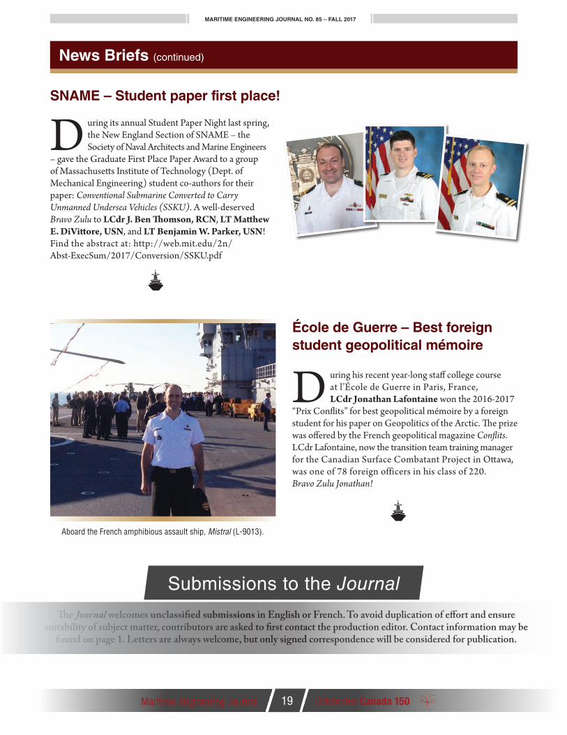
“Prix Conflits” for best geopolitical mémoire by a foreign student for his paper on Geopolitics of the Arctic. The prize was offered by the French geopolitical magazine Conflits. LCdr Lafontaine, now the transition team training manager for the Canadian Surface Combatant Project in Ottawa, was one of 78 foreign officers in his class of 220. Bravo Zulu Jonathan!
News Briefs (continued)
Aboard the French amphibious assault ship, Mistral (L-9013).
Submissions to the Journal
The Journal welcomes unclassified submissions in English or French. To avoid duplication of effort and ensure suitability of subject matter, contributors are asked to first contact the production editor. Contact information may be
found on page 1. Letters are always welcome, but only signed correspondence will be considered for publication.

MARITIME ENGINEERING JOURNAL NO. 85 – FALL 2017
Maritime Engineering Journal 20 Celebrates Canada 150
News Briefs (continued)
www.witconferences.com/defence2018
18 – 20 April 2018MaltaOrganised byWessex Institute, UK
University of Malta, Malta
Sponsored byWIT Transactions on the Built Environment
International Journal of Heritage Architecture
DEFENCE HERITAGE 2018
www.witconferences.com/defence2018
Call for Papers
4th International Conference on Defence Sites: Heritage and Future
T he Focus on Innovation event at the HMCS Bytown naval mess on June 19 featured three retirees (see inside cover) whose perspectives had
strong relevance for the RCN of today. Former senior naval engineer and Associate ADM(Mat) RAdm (ret.) Bill Christie said he was impressed by the cohesiveness of today’s technical personnel who must manage the complexities of modern-day specification writing, but cautioned that “we sometimes allow ourselves to become submerged in paperwork.”
Capt(N) (ret.) Jim Carruthers, the then national president of the Naval Association of Canada, and a former RCN Combat Systems Engineer, is perhaps best known for his innovative contribution to the Shipboard Integrated Processing and Display System (SHINPADS). “We spent eight years trying to convince people that ships could run off computers,” he said, “but if you had an idea and could do things, the leadership would let you go ahead.”
RAdm (ret.) Eldon Healey, a one-time Chief of Engineering and Maintenance and ADM(Mat), said his service as program manager for the Canadian Patrol Frigate
DGMEPM Mentorship Program – Innovation
project was the highlight of his career. “We need to be able to take risk,” he said, “and tough leadership works. Jim Carruthers brought us into the modern era with digital capability second to none. People thought we were crazy at first.”
Informal luncheon following the mentorship event gave attendees a chance to discuss the topic in further detail.
Pho
to b
y B
rian
McC
ullo
ugh

MARITIME ENGINEERING JOURNAL NO. 85 – FALL 2017
Maritime Engineering Journal 21 Celebrates Canada 150
News Briefs (continued)
CRCN Town Hall Visit with MEPM
R oyal Canadian Navy (RCN) Commander VAdm Ron Lloyd and RCN Command Chief CPO1 Michel Vigneault made a Town Hall visit
to the Maritime Equipment Program Management (MEPM) division in Gatineau in September to offer a high-level overview of the issues affecting the Navy today, and to respond to people's individual questions and concerns.
Chief Vigneault, a 34-year Navy veteran, also took the opportunity to model the RCN's smart-looking new Naval Combat Dress (NCD) for everyday wear on board ship and within naval establishments, and between home and work.
VAdm Lloyd spoke about the superb effectiveness of the RCN's current fleet, and the importance of the Navy's future ship programs in relation to recent global affairs and Canada's new Defence Policy: Strong , Secure, Engaged. He also answered a broad range of questions from members of MEPM, and highlighted the Navy's need to work harder to achieve strength through full gender and ethnic diversity by fostering a better environment of inclusiveness.
"Inclusion leads to diversity, and we are not as inclusive as we should be," he said. "We talk about inclusion and diversity as a strength because it is."
CD 1st Clasp
Cdr Daniel Salvage (DNPS)
VAdm Lloyd reassured those in uniform that the RCN is "looking at all factors" relating to sea time and to better career-family considerations so that naval personnel don't have to choose between family and the Navy.
The admiral also presented a number of awards during his Town Hall gathering.
continued on next page
Pho
to b
y B
rian
McC
ullo
ugh
Pho
to b
y B
rian
McC
ullo
ugh

MARITIME ENGINEERING JOURNAL NO. 85 – FALL 2017
Maritime Engineering Journal 22 Celebrates Canada 150
News Briefs (continued)
CRCN Commendations:Gilles Labrie (Damage Control Systems Technical Authority) – Mr. Labrie drove the accelerated implementa-tion of a Halon replacement system on board HMCS Chicoutimi, directly managing contractor support, and providing round-the-clock technical guidance to augment coastal expertise so that Chicoutimi could sail in August to meet a major operational commitment.
Steve Chan (Kingston- and Orca-class Platform Man-ager) – For more than 20 years Mr. Chan has been provid-ing expert technical support to the Kingston-class MCDVs
Canadian Forces Decoration (CD) and, more recently, the Orca-class patrol vessels. His steadfast determination and passion for the RCN enabled increased readiness and continuous operation of these platforms.
LCdr Jason Irwin (Non-Combatant Class Program Coordinator) – For his unwavering dedication and sheer passion for continuously improving the business of our business. LCdr Irwin consistently goes above and beyond to ensure the Non-Combatant program metrics provide an accurate picture to enable fact-based decision-making.
PO2 Chris Meredith (Small Boats Life Cycle Materiel Manager) – PO2 Meredith expertly communicates, manages and advises coastal fleet authorities on schedule conflicts and operational demands while maintaining fleet boat availability. An example of his significant contribution to the RCN was the timely implementation and outstanding support to the RCN Defender Project, and to small boats for DND.
Brian McCullough (Production Editor Maritime Engineering Journal) – For the past 35 years Mr. McCullough has overseen the development, editing and production of the Maritime Engineering Journal. His stalwart support, brilliant leadership, and expert advice in his role as editor have produced innovative, engaging, and widely read journals since 1982. This was his second Commander RCN Commendation.
Lt(N) Denise Dickson (DNPS), Lt(N) David Pittis (DNPS)
Brian McCulloughLCdr Jason Irwin, Gilles Labrie, PO2 Chris Meredith, and Steve Chan
Pho
to b
y B
rian
McC
ullo
ugh
Pho
to b
y C
PO
2 S
erge
Bai
llarg
eon
Pho
to b
y B
rian
McC
ullo
ugh

Hold that thought!
When members of the CNTHA get together to comment on a topic of historical interest, the discussion
often includes personal memories of events that are connected to the original point. The meeting notes normally capture what was shared in person, and amplifying notes are sometimes prepared after the fact, but some of the information shared in email threads can easily become buried or lost under the sheer volume of electronic mail.
At the regular meeting held on Sept. 21, the team explored ways to capture, edit and
During the Second World War the predecessors of the RCN Electrical (L) Branch were the radar officers
trained in Canada and loaned to the Royal Navy for service in capital ships; the officers who fulfilled duties associated with ship’s power and electronics; and the ratings from the torpedo, ASDIC (now sonar), and communications trades, including those trained in radio direction-finding (now known as radar). Around the time the war ended, the L Branch was formed from the nucleus of those officers and men who chose to remain in the Navy.
The responsibilities of the branch covered power generation and distribution, logs, plots, gyros, motors, generators, internal communi-cation, radar, external communications, and the electrical/electronic components of guns and sonars. Officers were expected to be knowledgeable in all these areas, but ratings were somewhat more specialized. The generally accepted academic qualification for officers was a degree in electrical engineering, although those with an engineering physics or other acceptable science degree could qualify. Ratings were required to have a Grade 10 education, which in the post-war era was a high require-ment as most other trades in the Navy were open to those with a Grade 8 education.
preserve key segments of these important online conversation strings so that the details will be available for future reference. Several members of the committee are testing a possible method for doing this in as easy a way as possible.
The following item from retired Navy Electrical Officer Pat Barnhouse is a perfect example of an amplifying note he submitted to the CNTHA committee further to a regular meeting discussion.
By Pat Barnhouse
CNTHA News Est. 1997
CNTHA ChairmanPat Barnhouse
CNTHA Executive DirectorTony Thatcher
Directorate of History and Heritage LiaisonMichael Whitby
Maritime Engineering Journal Liaison
Brian McCullough
Newsletter Production EditingServices by
Brightstar Communications (Kanata, ON)
in association with d2k Graphic Design & Web
(Gatineau, QC)
CNTHA News is the unofficial newsletter of the Canadian Naval
Technical History Association. Please address all correspondence
to the publisher, attention Michael Whitby, Chief of the
Naval Team, Directorate of History and Heritage, NDHQ
101 Colonel By Dr Ottawa, ON K1A 0K2 Tel. (613) 998-7045 Fax (613) 990-8579
Views expressed are those of the writers and do not necessarily
reflect official DND opinion or policy. The editor reserves the right to
edit or reject any editorial material.
www.cntha.ca
preserving canada’s naval technical heritage
Canadian Naval Technical History Association
News
Maritime Engineering Journal 23 Celebrates Canada 150
The Short Life of the Electrical Branch
CNTHA
In-service training for officers was at first ad hoc, but by 1950 the first Long Electrical Officers Long L) Course was underway. Officers commissioned from the ranks were given a year-long technical course tailored to areas of technology to which they had not been exposed as ratings.
Ratings all joined as Ordinary Seaman Electricians Mate Standard (OSLMS), and after basic training proceeded to sea for OJT. Here they qualified as ABLM1 (the “1” standing for Trade Group 1). This was followed by their first technical course where they divided into training as an ET (electrical technician), or RT (radio/radar technician – later called LT). At the end of this course their rank and trade group were usually LSET3 or LSRT3. Their next course (Trade Group 4) was as a petty officer 2nd class, and here the ETs were further divided into ET (power generation and distribution, logs, plots, etc.), ED (sonar), or EG (fire control). Comple-tion of this course usually saw them promoted petty officer 1st class Trade Group 4. Beyond this qualification there was also a chief’s course required to become a CPO 1st class.
continued on next page

MARITIME ENGINEERING JOURNAL NO. 85 – FALL 2017
Maritime Engineering Journal 24 Celebrates Canada 150
CNTHA News – Continued
Colin Brown: Welcome, Bruce. The first ships to be designed and built in Canada for the RCN were the St. Laurent class in the early 1950s, and as you had some naval service associated with Canadian industry at that time, some record of your experience with the 205 program may be useful for future historians.
Bruce Wilson: In 1945 I applied to the new Electrical Branch of the Navy while I was on a two-year course at Royal Roads, the Royal Canadian Naval College. After graduating university in 1949, I attended the long Electrical Officers Course in Halifax, and a few years later was picked to go to the Westinghouse plant in Hamilton, Ontario to augment the staff of the Resident Naval Overseer (RNO). While I was there from about November of ’53 to February of ’55 I got involved with the DDE-205 program, working on the electrical power equipment – the motors and motor starters, controllers, and all the basic power stuff.
Colin Brown: What did the RNO job actually consist of? Were you inspecting?
Bruce Wilson: To a certain extent. More testing than inspecting, as we had our Inspection Services there for that. The function of the RNO was to facilitate the delivery of electrical equipment from Westinghouse so that it could be fitted in the ships. The equipment was all designed to military specifications. Our function was to ensure that the equipment that was designed by Westinghouse to meet the specifications was promptly forwarded to headquarters for preliminary approval. The first-off on each of the productions was given what they call a periodic test, which was fairly extensive, and it was our responsibility on the RNO staff to ensure that all the tests were properly carried out. The equipment would eventually be delivered to the shipyards as Government furnished equipment.
Colin Brown: Did Westinghouse have any difficulty meeting the Navy’s requirements?
Bruce Wilson: Westinghouse had a particular way of doing things, and there was one incident when a chap in our Inspection Services who wasn’t quite as familiar with the work as he should have been turned down about fifty rotors. It was general practice at Westing-house to balance the rotors by drilling a small hole in the laminations to take out some of the metal, but this chap was turning them down because they had holes in them. The engineer came down to the office, but the inspector was standing firm on his decision. The RNO proposed a solution to put the equipment under a severe test, and if it passed he would accept it. I think everybody knew that the method was not going to affect anything, and of course, everything passed. It was a way to let Inspection Services save face.
Colin Brown: How would you describe your relationship with Westinghouse? Friendly?
Bruce Wilson: We usually worked together very well to get the job done. There was one time when some circuit-breakers were brought in from the Westinghouse main plant in the United States. Most of them were bearing little red tags, meaning they’d been rejected by inspectors, and there was a note attached that read, ‘These have been red tagged down here for the U.S. Navy. Maybe we can pass them off on the Canadians.’ I thought it was pretty friendly of our Westing-house man to show me what they had to contend with.
Colin Brown: The start of the St. Laurent class saw the big change from DC to AC, certainly in the generators. Was this a problem for you fellows when you were getting this equipment from Westing-house, and seeing it go into the ships, and training different people?
Bruce Wilson: Not at all. It was a blessing. There was a big drop in the workload because the amount of maintenance required for a DC motor is astronomical compared to an AC motor. Not only that, but our technicians already had experience with DC AC generators in the ship, and they were familiar with AC because they saw it at home. It wasn’t a major change for them, so it wasn’t a problem at all.
Colin Brown: Thank you very much, Bruce.
*The full interview transcript may be found at: http://www.cntha.ca/static/documents/oral_histories/b.wilson-2.pdf
The following is an edited excerpt* from a 2005 interview conducted by Colin Brown on behalf of the CNTHA’s Oral History Program with Bruce Wilson, resident naval overseer for electrical power equipment for the DDE-205 St. Laurent class:
HMCS St. Laurent
There was a subset of this system involved with support of naval air. Following their Long L Course, some Electrical Officers were recruited into the naval air service and were qualified through a mixture of equipment courses and familiarization periods with the RN or United States Navy. The electrical ratings followed a separate stream from their shipboard counterparts with courses training them as EAs or RAs.
The demise of the Electrical Branch came around 1960 with implementation of the Tisdall Report, but that’s another story.