simultaneous laser ranging and communication from an ... laser ranging and communication from an...
TRANSCRIPT

Simultaneous laser ranging and communication from an Earth-based satellite laser ranging station to the Lunar Reconnaissance Orbiter in lunar orbit
Xiaoli Sun*a, David R. Skillmana, Evan D. Hoffmanb, Dandan Maoc, Jan F. McGarrya, Gregory A. Neumanna, Leva McIntired, Ronald S. Zellara, Frederic M. Davidsone, Wai H. Fonga,
Michael A. Krainaka, Maria T. Zuberf, David E. Smitha,f
aNASA Goddard Space Flight Center, Code 694/599/567/554, Greenbelt, MD, USA 20771; bHoneywell Technology Solutions Inc., Columbia, MD, USA 21046; cSigma Space Corp.,
Lanham, MD, USA 20706; dCatholic University of America, Washington, DC, USA 20064; eDept. ECE, Johns Hopkins University, Baltimore, MD, USA 21218;
fDept. EAPS, MIT, Cambridge, MA, USA 02139
ABSTRACT
We report a free space laser communication experiment from the satellite laser ranging (SLR) station at NASA Goddard Space Flight Center (GSFC) to the Lunar Reconnaissance Orbiter (LRO) in lunar orbit through the on board one-way Laser Ranging (LR) receiver. Pseudo random data and sample image files were transmitted to LRO using a 4096-ary pulse position modulation (PPM) signal format. Reed-Solomon forward error correction codes were used to achieve error free data transmission at a moderate coding overhead rate. The signal fading due to the atmosphere effect was measured and the coding gain could be estimated. Keywords: Laser range finder, lidar, free-space optical communication, error correction coding.
1. INTRODUCTION Laser systems can be used to track and communicate with spacecraft in deep space to achieve better performance with lower power and smaller size transmitter and receiver aperture than conventional microwave systems. Lasers have been used to track Earth orbiting satellites and lunar retro-reflective arrays on the lunar surface for over 40 years [1]. Recently, NASA GSFC has developed a one-way laser ranging system to track LRO in lunar orbit for precision orbit determination [2]. Meanwhile, free space laser communication technologies have been under development over the past 30 years and several experiments have been successfully conducted [3-4]. A 5.6 Gbps optical communication link between two Low-Earth Orbit (LEO) satellites, NFIRE (US) and TerraSAR-X (Germany) using German Tesat-Spacecom terminals, has recently been demonstrated [5]. The Lunar Laser Communication Demonstration (LLCD) will be the first two-way high speed (622Mbps) lunar laser communication demonstration to be launched in August 2013 on board the Lunar Atmosphere and Dust Environment Explorer (LADEE) [6]. The Laser Communication Relay Demonstration (LCRD) at 1.25 Gbps to geosynchronous satellites is currently under development at NASA GSFC with an anticipated launch date in 2016 [7]. Laser ranging and communication can be combined into a single laser transmitter receiver system because the two signals occupy widely separate frequency bands and can be individually filtered out at the receiver without interference. The signal in laser ranging is slowly varying and requires only one measurement every few seconds to track a spacecraft in deep space. The signals in laser communication are usually fast transitions between discrete digital levels at discrete time. _______________________________________________ *[email protected]; phone 301 614-6732; fax 301 614-6744
Invited Paper
Free-Space Laser Communication and Atmospheric Propagation XXV, edited by Hamid Hemmati,Don M. Boroson, Proc. of SPIE Vol. 8610, 861003 · © 2013 SPIE
CCC code: 0277-786X/13/$18 · doi: 10.1117/12.2006645
Proc. of SPIE Vol. 8610 861003-1
Downloaded From: http://proceedings.spiedigitallibrary.org/ on 03/27/2013 Terms of Use: http://spiedl.org/terms
https://ntrs.nasa.gov/search.jsp?R=20150019783 2018-06-29T02:21:58+00:00Z

There are many common aspects between satellite laser ranging (SLR) and free-space laser communication systems, such as laser beam pointing, atmosphere effect correction, and time synchronization. A free space laser communication system can provide ranging data as a byproduct of the digital data clock recovery. A laser ranging system can be used to send data by digitally modulating the laser pulses. The major differences between the two are the transmitted data rate. A dedicated free-space laser communication system can transmit data at hundreds of Mbits/s while SLR system may only transmit data up to several kbits/s due to the limitations of the existing equipment. On the other hand, SLR is a mature technology with many SLR stations around the globe [8]. They can be modified slightly to allow data to ride on the laser tracking beams and share most of the existing infrastructure. A low data rate free-space communication system is useful for uplink and downlink commands and housekeeping data between Earth and spacecraft in deep space using existing SLR stations. Using SLR stations to transfer times to Earth orbiting satellites has been demonstrated [9-10] and to the Mercury Laser Altimeter on the MESSENGER spacecraft over 24x106 km [11]. Simultaneous ranging and communication using a PPM signal format from an SLR station to Earth orbiting satellites has been proposed and a ground-based demonstration has been conducted [12]. LLCD will demonstrate simultaneous communication and ranging by phase locking the uplink and downlink digital data clocks on LADEE [6]. We have recently conducted a series of simultaneous laser ranging and communication experiments from the Next Generation Satellite Laser Ranging (NGSLR) station at NASA Goddard Space Flight Center (GSFC) in Greenbelt, Maryland to the Lunar Reconnaissance Orbiter (LRO) in lunar orbit [13]. The experiments used 4096-ary pulse position modulation (PPM) and Reed-Solomon forward error correction codes (FEC) with 4096-ary symbol size and achieved 200-300 bits/s data rate error free through various atmosphere conditions. The experiments provided direct measurements of laser signal fading due to atmospheric turbulence and pointing jitter from a typical SLR station to a spacecraft in deep space.
2. TEST SETUP 2.1 The LRO LR receiver in lunar orbit
The receiver used in this simultaneous laser ranging and communication experiment is the LRO laser ranging (LR) receiver [2] on the high gain antenna, which is pointed to Earth whenever LRO is in view from Earth. The LRO LR receiver has a 2.2-cm diameter telescope mounted on and co-bore-sighted with the spacecraft high gain antenna, which can detect laser pulses from SLR stations on Earth when LRO is in direct line of sight. The received laser pulses at LRO are sent via an optical fiber bundle to the Lunar Orbiter Laser Altimeter (LOLA) [14] and time-tagged at <0.5 ns precision with respect to the spacecraft Mission Elapsed Time (MET). The LOLA receiver consists of a silicon avalanche photodiode (APD) with enhanced near infrared response. The LOLA flight laser is at 1064 nm wavelength and the LR uplink receiver measurement is at 532 nm wavelength. There is a dichroic beam splitter/combiner that combines the two optical signals onto the same APD. The receiver electronics records the arrival time (time tag) of each detected laser pulse within two designated range-gate windows, an 8-ms LR window for the LR pulses from Earth and a short lunar laser range window for the LOLA lunar laser ranging pulses. The LOLA laser pulse rate of 28Hz provides contiguous coverage along track on the lunar surface. The receiver electronics records the arrival times of the first pulse in the window. The LR receiver sensitivity is ~0.1 fJ/pulse at the APD, or about 0.05 fJ/cm2 at the entrance of the LR telescope at the high gain antenna. Most of the SLR stations on Earth use the 532 nm wavelength and are capable of delivering laser pulses at this energy level with >10 dB link margin at lunar distance. The LRO clock is derived from an ultra-stable ovenized quartz oscillator, which has demonstrated a 2x10-13 midterm stability in orbit after removing a predicted aging rate and the known temperature effects. The LRO Mission Operation Center (MOC) is capable of predicting the LRO time to <<3ms via routine time keeping operations. LRO also provides a low data rate feedback to the LR stations to indicate the detection of LR pulses and report the average times of the LR pulses within the LR range window each second. The LR stations fine tune the pointing and timing to maximize the detection of the LR laser pulses within the LR range window. Because the LRO clock frequency offset is so small that the residual timing uncertainty drift during a one-hour LR session is <<1 μs after an initial time offset is removed. The
Proc. of SPIE Vol. 8610 861003-2
Downloaded From: http://proceedings.spiedigitallibrary.org/ on 03/27/2013 Terms of Use: http://spiedl.org/terms

Laser pulses transmittedfrom the earth stationtime -stamped wrt UTC
Laser pulsesreceived by LOLAtime -stampedwrt UTC via MET
28 Hz,
LR receiver FOV to cover both theRF ground station (White Sand) andall possible laser tracking stations
Laser time -of- flight time(relative range, velocity, and Doppler shift)
Opticalreceiver
fiberbundle
HGA
-4-----II
LOLA
LOLA receiveroperation cycle(128) sec
n+1
I i i I i i ff i l I
PPM symbol H
One laser pulse in
one of the 212 time slotsrepresenting 12 binary bits
Atslot
ztsslot =1µs, 212 slots, 4tsymbol= 4.096ms
Raw date rate = 28 symbols/s * 12 bits/symbol = 336 bits/s(12bits/4.096ms = 2.9 kbits/s burst rateif no wait time between symbols)
LRO LR system has been in operation since June 2009 and the range window time can be predicted well enough to allow ground stations such as NGSLR to place the LR pulses anywhere within the range-gate window thus making simultaneous laser communication and ranging feasible. LRO LR is a one-way laser ranging system. The time tags of the LR pulses at LRO are transmitted back to Earth via the microwave communication link. The ground data processing team pairs up the laser pulse arrival time with the corresponding laser pulse emission times recorded by the SLR station to obtain the difference of the two time tags. As long as the clock oscillators are sufficiently stable, the LR measurement gives the distance from the ground station to LRO except for a constant offset. The data can be used to assist the LRO orbit position determination. Figure 1 shows a diagram of the LRO LR system. Figure 2 shows the timing diagram and the PPM signaling of the laser trigger.
Figure 1. LRO-LR concept. The LR receiver telescope is embedded in the LRO high gain antenna for co-bore-sighted pointing. The optical signal is sent down the antenna via an optical fiber bundle to LOLA for time tagging. The clock oscillator at both LRO and the ground station are sufficiently stable and can be considered to have a constant frequency during a two-hour LRO orbit. The difference of the time tags at LRO and the ground station gives a one-way laser ranging measurement which is used for LRO orbit determination.
Figure 2. Timing diagram of the LOLA receiver and PPM signaling of the laser trigger.
Proc. of SPIE Vol. 8610 861003-3
Downloaded From: http://proceedings.spiedigitallibrary.org/ on 03/27/2013 Terms of Use: http://spiedl.org/terms
2.2 Ground station - NGSLR
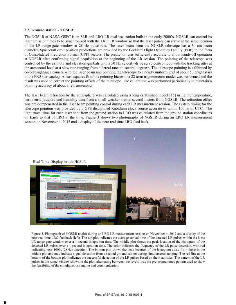
The NGSLR at NASA-GSFC is an SLR and LRO-LR dual-use station built in the early 2000’s. NGSLR can control its laser emission times to be synchronized with the LRO LR window so that the laser pulses can arrive at the same location of the LR range-gate window at 28 Hz pulse rate. The laser beam from the NGSLR telescope has a 30 cm beam diameter. Spacecraft orbit position predictions are provided by the Goddard Flight Dynamics Facility (FDF) in the form of Consolidated Prediction Format (CPF) vectors. The prediction was sufficiently accurate to allow hands-off operation at NGSLR after confirming signal acquisition at the beginning of the LR session. The pointing of the telescope was controlled by the azimuth and elevation gimbals with a 50 Hz velocity drive servo control loop with the tracking jitter at the arcsecond level at a slew rate ranging from sidereal rates to several degree/s. The telescope pointing is calibrated by co-boresighting a camera with the laser beam and pointing the telescope to a nearly uniform grid of about 50 bright stars in the FK5 star catalog. A least squares fit of the pointing biases to a 22 term trigonometric model was performed and the result was used to correct the pointing offsets of the telescope. The calibration was performed periodically to maintain a pointing accuracy of about a few arcsecond. The laser beam refraction by the atmosphere was calculated using a long established model [15] using the temperature, barometric pressure and humidity data from a small weather station several meters from NGSLR. The refraction effect was pre-compensated in the laser beam pointing control during each LR measurement session. The system timing for the telescope pointing was provided by a GPS disciplined Rubidium clock source accurate to within 100 ns of UTC. The light travel time for each laser shot from the ground station to LRO was calculated from the ground station coordinates on Earth to that of LRO at the time. Figure 3 shows two photographs of NGSLR during an LRO LR measurement session on November 4, 2012 and a display of the near real time LRO feed back.
Figure 3. Photograph of NGSLR (right) during an LRO LR measurement session on November 4, 2012 and a display of the near real time LRO feedback (left). The top plot indicates the average arrival time of the detected LR pulses within the 8-ms LR range-gate window over a 1-second integration time. The middle plot shows the peak location of the histogram of the detected LR pulses over a 1-second integration time. The color indicates the frequency of the LR pulse detection, with red indicating near 100% (28Hz) detection. The bottom plot shows the peak location of the histogram away from those in the middle plot and may indicate signal detection from a second ground station during simultaneous ranging. The red line at the bottom of the bottom plot indicates the successful detection of the LR pulses based on their statistics. The pattern of the LR pulses in the range window shown in the plot, alternating between two levels, was the pre-programmed pattern used to show the feasibility of the simultaneous ranging and communication.
Real Time Display inside NGSLR
Radar
Proc. of SPIE Vol. 8610 861003-4
Downloaded From: http://proceedings.spiedigitallibrary.org/ on 03/27/2013 Terms of Use: http://spiedl.org/terms
AntennaInitial phaseadjustment
28Hz PPM symbol clock
LRO orbit PPM symbolpredicts sequence
2.3 PPM Signal Generation
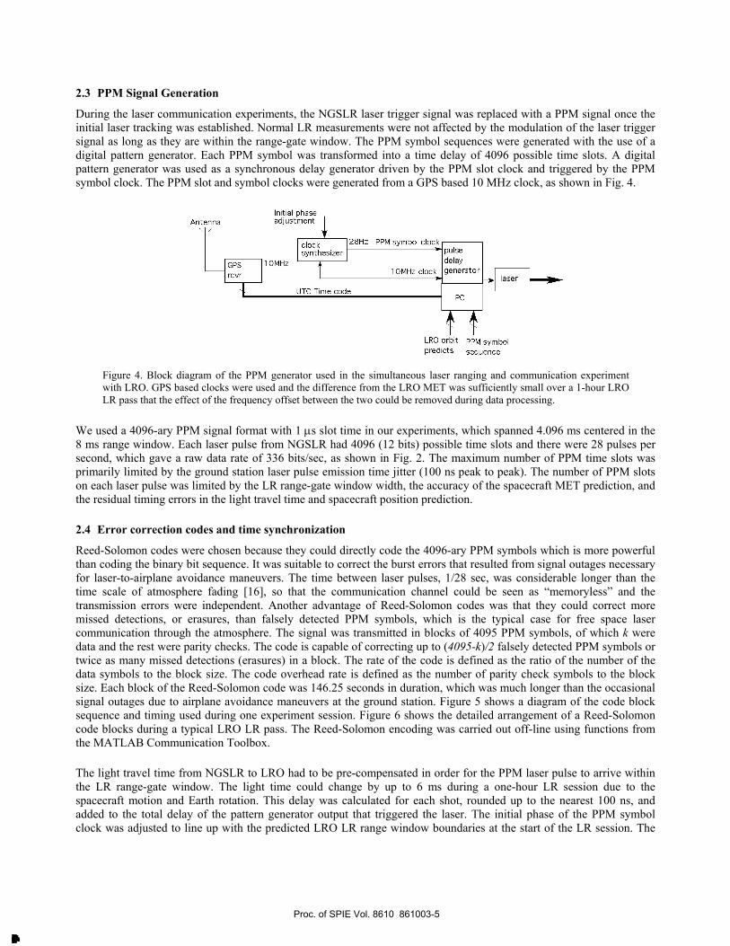
During the laser communication experiments, the NGSLR laser trigger signal was replaced with a PPM signal once the initial laser tracking was established. Normal LR measurements were not affected by the modulation of the laser trigger signal as long as they are within the range-gate window. The PPM symbol sequences were generated with the use of a digital pattern generator. Each PPM symbol was transformed into a time delay of 4096 possible time slots. A digital pattern generator was used as a synchronous delay generator driven by the PPM slot clock and triggered by the PPM symbol clock. The PPM slot and symbol clocks were generated from a GPS based 10 MHz clock, as shown in Fig. 4.
Figure 4. Block diagram of the PPM generator used in the simultaneous laser ranging and communication experiment with LRO. GPS based clocks were used and the difference from the LRO MET was sufficiently small over a 1-hour LRO LR pass that the effect of the frequency offset between the two could be removed during data processing.
We used a 4096-ary PPM signal format with 1 μs slot time in our experiments, which spanned 4.096 ms centered in the 8 ms range window. Each laser pulse from NGSLR had 4096 (12 bits) possible time slots and there were 28 pulses per second, which gave a raw data rate of 336 bits/sec, as shown in Fig. 2. The maximum number of PPM time slots was primarily limited by the ground station laser pulse emission time jitter (100 ns peak to peak). The number of PPM slots on each laser pulse was limited by the LR range-gate window width, the accuracy of the spacecraft MET prediction, and the residual timing errors in the light travel time and spacecraft position prediction. 2.4 Error correction codes and time synchronization
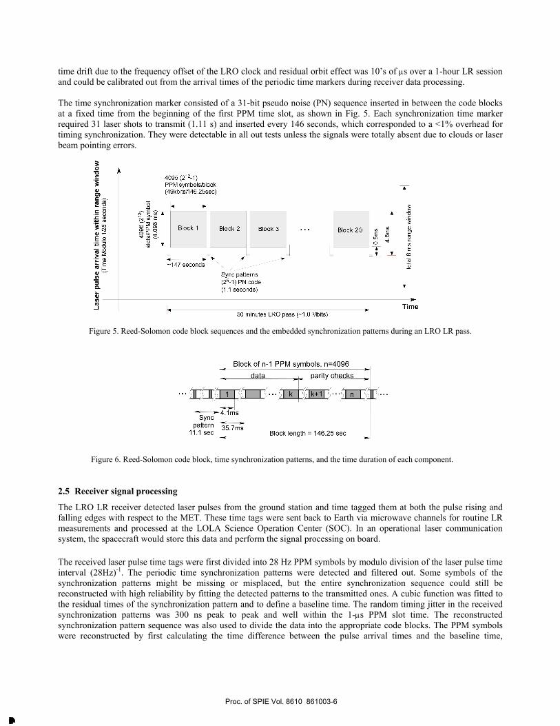
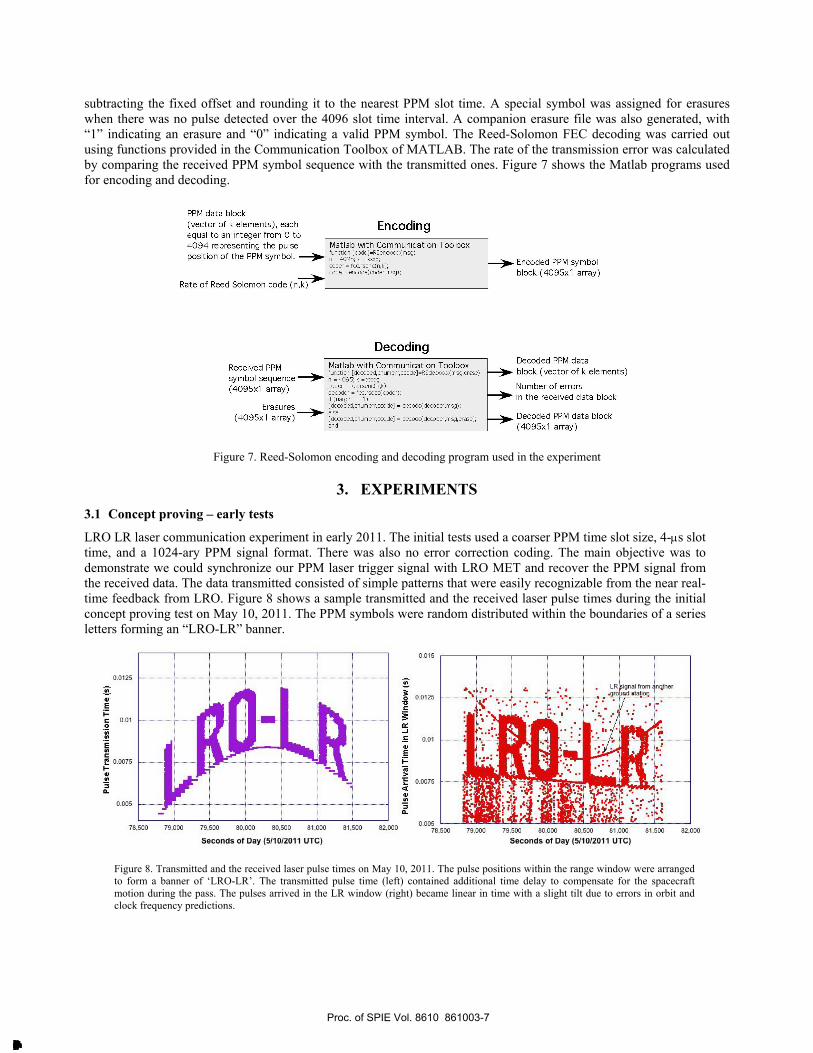
Reed-Solomon codes were chosen because they could directly code the 4096-ary PPM symbols which is more powerful than coding the binary bit sequence. It was suitable to correct the burst errors that resulted from signal outages necessary for laser-to-airplane avoidance maneuvers. The time between laser pulses, 1/28 sec, was considerable longer than the time scale of atmosphere fading [16], so that the communication channel could be seen as “memoryless” and the transmission errors were independent. Another advantage of Reed-Solomon codes was that they could correct more missed detections, or erasures, than falsely detected PPM symbols, which is the typical case for free space laser communication through the atmosphere. The signal was transmitted in blocks of 4095 PPM symbols, of which k were data and the rest were parity checks. The code is capable of correcting up to (4095-k)/2 falsely detected PPM symbols or twice as many missed detections (erasures) in a block. The rate of the code is defined as the ratio of the number of the data symbols to the block size. The code overhead rate is defined as the number of parity check symbols to the block size. Each block of the Reed-Solomon code was 146.25 seconds in duration, which was much longer than the occasional signal outages due to airplane avoidance maneuvers at the ground station. Figure 5 shows a diagram of the code block sequence and timing used during one experiment session. Figure 6 shows the detailed arrangement of a Reed-Solomon code blocks during a typical LRO LR pass. The Reed-Solomon encoding was carried out off-line using functions from the MATLAB Communication Toolbox. The light travel time from NGSLR to LRO had to be pre-compensated in order for the PPM laser pulse to arrive within the LR range-gate window. The light time could change by up to 6 ms during a one-hour LR session due to the spacecraft motion and Earth rotation. This delay was calculated for each shot, rounded up to the nearest 100 ns, and added to the total delay of the pattern generator output that triggered the laser. The initial phase of the PPM symbol clock was adjusted to line up with the predicted LRO LR range window boundaries at the start of the LR session. The
Proc. of SPIE Vol. 8610 861003-5
Downloaded From: http://proceedings.spiedigitallibrary.org/ on 03/27/2013 Terms of Use: http://spiedl.org/terms
4095 (212-1)PPM symbols/block(49kbits /146.25sec)
Block 1
-147 seconds
Block 2 Block 3
1
Sync patterns(25-1) PN code(1.1 seconds)
Block 20
50 minutes LRO pass ( -1.0 Mbits)
Block of n -1 PPM symbols, n =4096
data arit checks
IA I ... 1©
Syncpattern
11.1 sec35.7ms
Block length = 146.25 sec
time drift due to the frequency offset of the LRO clock and residual orbit effect was 10’s of μs over a 1-hour LR session and could be calibrated out from the arrival times of the periodic time markers during receiver data processing. The time synchronization marker consisted of a 31-bit pseudo noise (PN) sequence inserted in between the code blocks at a fixed time from the beginning of the first PPM time slot, as shown in Fig. 5. Each synchronization time marker required 31 laser shots to transmit (1.11 s) and inserted every 146 seconds, which corresponded to a <1% overhead for timing synchronization. They were detectable in all out tests unless the signals were totally absent due to clouds or laser beam pointing errors.
Figure 5. Reed-Solomon code block sequences and the embedded synchronization patterns during an LRO LR pass.
Figure 6. Reed-Solomon code block, time synchronization patterns, and the time duration of each component.
2.5 Receiver signal processing
The LRO LR receiver detected laser pulses from the ground station and time tagged them at both the pulse rising and falling edges with respect to the MET. These time tags were sent back to Earth via microwave channels for routine LR measurements and processed at the LOLA Science Operation Center (SOC). In an operational laser communication system, the spacecraft would store this data and perform the signal processing on board. The received laser pulse time tags were first divided into 28 Hz PPM symbols by modulo division of the laser pulse time interval (28Hz)-1. The periodic time synchronization patterns were detected and filtered out. Some symbols of the synchronization patterns might be missing or misplaced, but the entire synchronization sequence could still be reconstructed with high reliability by fitting the detected patterns to the transmitted ones. A cubic function was fitted to the residual times of the synchronization pattern and to define a baseline time. The random timing jitter in the received synchronization patterns was 300 ns peak to peak and well within the 1-μs PPM slot time. The reconstructed synchronization pattern sequence was also used to divide the data into the appropriate code blocks. The PPM symbols were reconstructed by first calculating the time difference between the pulse arrival times and the baseline time,
Proc. of SPIE Vol. 8610 861003-6
Downloaded From: http://proceedings.spiedigitallibrary.org/ on 03/27/2013 Terms of Use: http://spiedl.org/terms
PPM data block(vector of k elements), eachequal to an integer from 0 to4094 representing the pulseposition of the PPM symbol.
Rate of Reed Solomon code (n,k)
Received PPMsymbol sequence(4095x1 array)
Erasures(4095x1 array)
)116
EncodingMatlab with Communication Toolboxfunction [code] =RSer 0000r(msg)n = 4095; k = 000c;coder = fecrsenc(n,k);code = enmde(mder,msg);
DecodingMatlab with Communication Toolboxfunction [ demdegawmerr ,omde]= RSde0000r(msg,erase)n = 4095; k = >ow;coda = fecrsenc(n,k);decoder = fec.rsdeQmder);If (nargin == 1)[de oded,rnumerr,omdel = decode( deco der,m sg);else[demdegrnumerr,cmde] = decod$demder,msg,erase);end
Encoded PPM symbolblock (4095x1 array)
Decoded PPM datablock (vector of k elements)
Number of errorsin the received data block
Decoded PPM data block(4095x1 array)
0.0125
vE1Zc 0.01o
ECe 0.0075FNd
3R
0.005
i i i i i i
:...................... ......:. ... ... ........................:......;
78,500 79,000 79.500 80.000 80,500 81.000
Seconds of Day (5/10/2011 UTC)
81.500 82.000
0.015
0.0125
0.01
0.0075
0.00578.500 79.000 79.500 80.000 80.500 81.000 81,500
Seconds of Day (5/10/2011 UTC)82,000
subtracting the fixed offset and rounding it to the nearest PPM slot time. A special symbol was assigned for erasures when there was no pulse detected over the 4096 slot time interval. A companion erasure file was also generated, with “1” indicating an erasure and “0” indicating a valid PPM symbol. The Reed-Solomon FEC decoding was carried out using functions provided in the Communication Toolbox of MATLAB. The rate of the transmission error was calculated by comparing the received PPM symbol sequence with the transmitted ones. Figure 7 shows the Matlab programs used for encoding and decoding.
Figure 7. Reed-Solomon encoding and decoding program used in the experiment
3. EXPERIMENTS 3.1 Concept proving – early tests
LRO LR laser communication experiment in early 2011. The initial tests used a coarser PPM time slot size, 4-μs slot time, and a 1024-ary PPM signal format. There was also no error correction coding. The main objective was to demonstrate we could synchronize our PPM laser trigger signal with LRO MET and recover the PPM signal from the received data. The data transmitted consisted of simple patterns that were easily recognizable from the near real-time feedback from LRO. Figure 8 shows a sample transmitted and the received laser pulse times during the initial concept proving test on May 10, 2011. The PPM symbols were random distributed within the boundaries of a series letters forming an “LRO-LR” banner.
Figure 8. Transmitted and the received laser pulse times on May 10, 2011. The pulse positions within the range window were arranged to form a banner of ‘LRO-LR’. The transmitted pulse time (left) contained additional time delay to compensate for the spacecraft motion during the pass. The pulses arrived in the LR window (right) became linear in time with a slight tilt due to errors in orbit and clock frequency predictions.
Proc. of SPIE Vol. 8610 861003-7
Downloaded From: http://proceedings.spiedigitallibrary.org/ on 03/27/2013 Terms of Use: http://spiedl.org/terms
1.0
0.8
0.6
o tincodedRate 7/8 RS codeRate 3/4 RS codeRate 1/2 RS code -Curve fit to uncoiled
000.00 0.20 0.40 0.60 0.80
Average Received Pulse Energy (U)
1.00
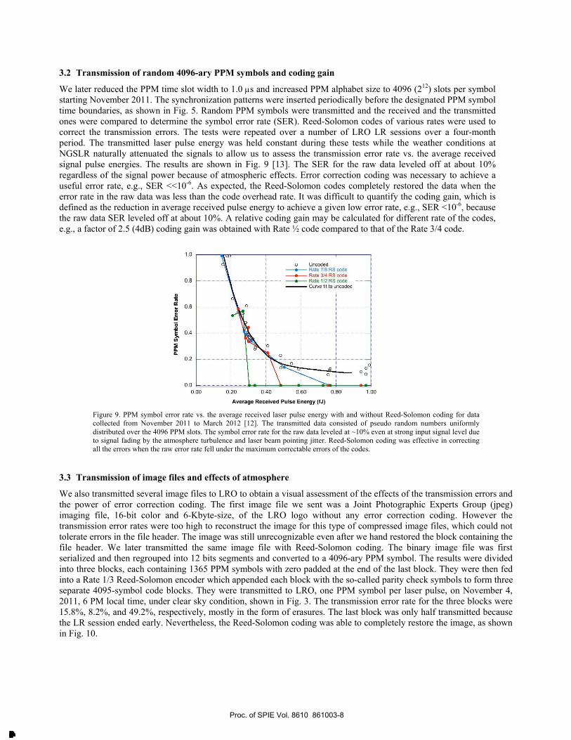
3.2 Transmission of random 4096-ary PPM symbols and coding gain
We later reduced the PPM time slot width to 1.0 μs and increased PPM alphabet size to 4096 (212) slots per symbol starting November 2011. The synchronization patterns were inserted periodically before the designated PPM symbol time boundaries, as shown in Fig. 5. Random PPM symbols were transmitted and the received and the transmitted ones were compared to determine the symbol error rate (SER). Reed-Solomon codes of various rates were used to correct the transmission errors. The tests were repeated over a number of LRO LR sessions over a four-month period. The transmitted laser pulse energy was held constant during these tests while the weather conditions at NGSLR naturally attenuated the signals to allow us to assess the transmission error rate vs. the average received signal pulse energies. The results are shown in Fig. 9 [13]. The SER for the raw data leveled off at about 10% regardless of the signal power because of atmospheric effects. Error correction coding was necessary to achieve a useful error rate, e.g., SER <<10-6. As expected, the Reed-Solomon codes completely restored the data when the error rate in the raw data was less than the code overhead rate. It was difficult to quantify the coding gain, which is defined as the reduction in average received pulse energy to achieve a given low error rate, e.g., SER <10-6, because the raw data SER leveled off at about 10%. A relative coding gain may be calculated for different rate of the codes, e.g., a factor of 2.5 (4dB) coding gain was obtained with Rate ½ code compared to that of the Rate 3/4 code.
Figure 9. PPM symbol error rate vs. the average received laser pulse energy with and without Reed-Solomon coding for data collected from November 2011 to March 2012 [12]. The transmitted data consisted of pseudo random numbers uniformly distributed over the 4096 PPM slots. The symbol error rate for the raw data leveled at ~10% even at strong input signal level due to signal fading by the atmosphere turbulence and laser beam pointing jitter. Reed-Solomon coding was effective in correcting all the errors when the raw error rate fell under the maximum correctable errors of the codes.
3.3 Transmission of image files and effects of atmosphere
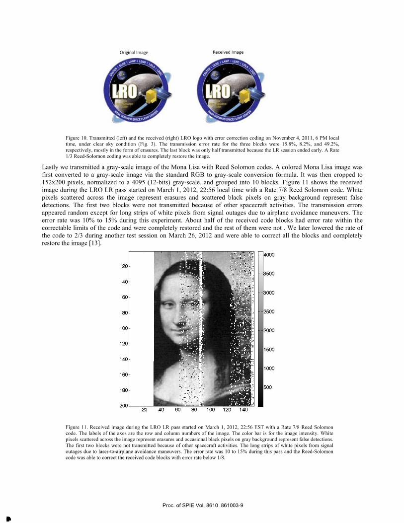
We also transmitted several image files to LRO to obtain a visual assessment of the effects of the transmission errors and the power of error correction coding. The first image file we sent was a Joint Photographic Experts Group (jpeg) imaging file, 16-bit color and 6-Kbyte-size, of the LRO logo without any error correction coding. However the transmission error rates were too high to reconstruct the image for this type of compressed image files, which could not tolerate errors in the file header. The image was still unrecognizable even after we hand restored the block containing the file header. We later transmitted the same image file with Reed-Solomon coding. The binary image file was first serialized and then regrouped into 12 bits segments and converted to a 4096-ary PPM symbol. The results were divided into three blocks, each containing 1365 PPM symbols with zero padded at the end of the last block. They were then fed into a Rate 1/3 Reed-Solomon encoder which appended each block with the so-called parity check symbols to form three separate 4095-symbol code blocks. They were transmitted to LRO, one PPM symbol per laser pulse, on November 4, 2011, 6 PM local time, under clear sky condition, shown in Fig. 3. The transmission error rate for the three blocks were 15.8%, 8.2%, and 49.2%, respectively, mostly in the form of erasures. The last block was only half transmitted because the LR session ended early. Nevertheless, the Reed-Solomon coding was able to completely restore the image, as shown in Fig. 10.
Proc. of SPIE Vol. 8610 861003-8
Downloaded From: http://proceedings.spiedigitallibrary.org/ on 03/27/2013 Terms of Use: http://spiedl.org/terms
Original Image Received Image
20
40
60
80
100
120
140
160
180
20020 40 60 80 100 120 140
4000
3500
3000
2500
2000
1500
1000
500
Figure 10. Transmitted (left) and the received (right) LRO logo with error correction coding on November 4, 2011, 6 PM local time, under clear sky condition (Fig. 3). The transmission error rate for the three blocks were 15.8%, 8.2%, and 49.2%, respectively, mostly in the form of erasures. The last block was only half transmitted because the LR session ended early. A Rate 1/3 Reed-Solomon coding was able to completely restore the image.
Lastly we transmitted a gray-scale image of the Mona Lisa with Reed Solomon codes. A colored Mona Lisa image was first converted to a gray-scale image via the standard RGB to gray-scale conversion formula. It was then cropped to 152x200 pixels, normalized to a 4095 (12-bits) gray-scale, and grouped into 10 blocks. Figure 11 shows the received image during the LRO LR pass started on March 1, 2012, 22:56 local time with a Rate 7/8 Reed Solomon code. White pixels scattered across the image represent erasures and scattered black pixels on gray background represent false detections. The first two blocks were not transmitted because of other spacecraft activities. The transmission errors appeared random except for long strips of white pixels from signal outages due to airplane avoidance maneuvers. The error rate was 10% to 15% during this experiment. About half of the received code blocks had error rate within the correctable limits of the code and were completely restored and the rest of them were not . We later lowered the rate of the code to 2/3 during another test session on March 26, 2012 and were able to correct all the blocks and completely restore the image [13].
Figure 11. Received image during the LRO LR pass started on March 1, 2012, 22:56 EST with a Rate 7/8 Reed Solomon code. The labels of the axes are the row and column numbers of the image. The color bar is for the image intensity. White pixels scattered across the image represent erasures and occasional black pixels on gray background represent false detections. The first two blocks were not transmitted because of other spacecraft activities. The long strips of white pixels from signal outages due to laser-to-airplane avoidance maneuvers. The error rate was 10 to 15% during this pass and the Reed-Solomon code was able to correct the received code blocks with error rate below 1/8.
Proc. of SPIE Vol. 8610 861003-9
Downloaded From: http://proceedings.spiedigitallibrary.org/ on 03/27/2013 Terms of Use: http://spiedl.org/terms

e
0.6
0.4
0.2
ej
0.8
1000 1500 2000 2500
Time from the beginning of the LR pass (sec)
',111111
0 100 200 300 400 500 600
Time Shift (sec)700 800 900 1000
4. ATMOSPHERE FADING The received pulse energy of each laser shot was recorded by LOLA [14], which gave a direct measurement of the signal fading due to Earth atmosphere. The correlation of the signal fading can be represented by the normalized autocovariance function. Assuming the signal fading is a stationary process, the autocovariance function can be approximated by the sample autocovariance function defined as
cxx (τ ) =x(ti )− x[ ]
i=0
N−nτ −1
∑ x(ti +τ )− x[ ]
x(ti )− x[ ]2
i=0
N−nτ
∑
where x =1N
x(ti )i=0
N−1
∑ is the mean of the received pulse energy, ti is the sample time binned to the PPM symbol intervals,
and τ is a time shift in multiple of PPM symbol intervals (28Hz)-1, nτ = τ / (1 / 28Hz) is the number of PPM symbols over the time interval τ . To evaluate the sample correlation function, we had to fill in an energy for each erased PPM symbol. Since the erasures were caused by low received energies, we filled in a random pulse energy ranging from zero to the detector threshold for every erased PPM symbol. Figure 12 shows the received laser pulse energy from the LRO LR pass starting on November 4, 2011, 6PM local time, and the resultant sample autocovariance function for data after the gap between 700 and 900 seconds. The gaps were a source of correlation and the big gap above was caused by the spacecraft or ground station maneuvers. The smaller gaps were due to laser-to-airplane avoidance maneuvers and they were included in the sample autocovariance function calculations because we believe they were a characteristic of typical free space communication systems. There was no apparent correlation in the atmosphere effects from one laser shot to the next at 28Hz. The weak correlation up to 20 sec was possibly caused by telescope pointing errors and brief gaps in the data from laser-to-airplane avoidance maneuvers. This confirmed that communication channel could be considered as memoryless.
Figure 12. Received laser pulse energy on November 4, 2011, 6PM local time and the resultant sample autocovariance function for data from 900 seconds to the end of the test session. The gap between 700 to 900 seconds was caused by the spacecraft or ground station maneuvers. The smaller gaps were due to laser-to-airplane avoidance maneuvers. The minimum detectable energy was 0.14 fJ and the LOLA pulse monitor saturated at about 7.8 fJ/pulse, showing as a near solid line in the top plot. A random number between zero and the minimum detectable signal was assigned for each erased PPM symbol.
Proc. of SPIE Vol. 8610 861003-10
Downloaded From: http://proceedings.spiedigitallibrary.org/ on 03/27/2013 Terms of Use: http://spiedl.org/terms
6000
5000
4000
3000
2000
I
OO
De ec ionthreshold
ex .
x 27LQZ
p=0.55, a =0.99
=Histogram- Lognormal Fit
[ (Inx-1021{L 2v2
2 3 4
Pu se Ene gy (fJ)7 t8
Out of range
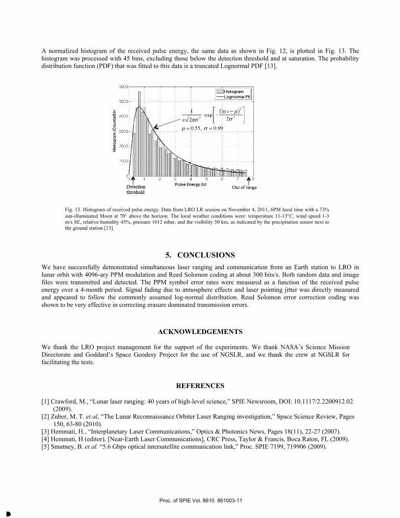
A normalized histogram of the received pulse energy, the same data as shown in Fig. 12, is plotted in Fig. 13. The histogram was processed with 45 bins, excluding those below the detection threshold and at saturation. The probability distribution function (PDF) that was fitted to this data is a truncated Lognormal PDF [13].
Fig. 13. Histogram of received pulse energy. Data from LRO LR session on November 4, 2011, 6PM local time with a 73% sun-illuminated Moon at 70° above the horizon. The local weather conditions were: temperature 11-13°C, wind speed 1-3 m/s SE, relative humidity 45%, pressure 1012 mbar, and the visibility 50 km, as indicated by the precipitation sensor next to the ground station [13].
5. CONCLUSIONS We have successfully demonstrated simultaneous laser ranging and communication from an Earth station to LRO in lunar orbit with 4096-ary PPM modulation and Reed Solomon coding at about 300 bits/s. Both random data and image files were transmitted and detected. The PPM symbol error rates were measured as a function of the received pulse energy over a 4-month period. Signal fading due to atmosphere effects and laser pointing jitter was directly measured and appeared to follow the commonly assumed log-normal distribution. Reed Solomon error correction coding was shown to be very effective in correcting erasure dominated transmission errors.
ACKNOWLEDGEMENTS
We thank the LRO project management for the support of the experiments. We thank NASA’s Science Mission Directorate and Goddard’s Space Geodesy Project for the use of NGSLR, and we thank the crew at NGSLR for facilitating the tests.
REFERENCES
[1] Crawford, M., “Lunar laser ranging: 40 years of high-level science,” SPIE Newsroom, DOI: 10.1117/2.2200912.02 (2009).
[2] Zuber, M. T. et al, “The Lunar Reconnaissance Orbiter Laser Ranging investigation,” Space Science Review, Pages 150, 63-80 (2010).
[3] Hemmati, H., “Interplanetary Laser Communications,” Optics & Photonics News, Pages 18(11), 22-27 (2007). [4] Hemmati, H (editor), [Near-Earth Laser Communications], CRC Press, Taylor & Francis, Boca Raton, FL (2009). [5] Smutney, B. et al. “5.6 Gbps optical intersatellite communication link,” Proc. SPIE 7199, 719906 (2009).
Proc. of SPIE Vol. 8610 861003-11
Downloaded From: http://proceedings.spiedigitallibrary.org/ on 03/27/2013 Terms of Use: http://spiedl.org/terms

[6] Boroson, D. M. et al “Overview and Status of the Lunar Laser Communications Demonstration,” Proc. SPIE 8246, 82460C (2012).
[7] NASA Technology Demonstration Mission, http://www.nasa.gov/mission_pages/tdm/lcrd/index.html (2012). [8] Pearlman, M. R.; Degnan, J. J.; and Bosworth, J. M., “The international laser ranging service,” Advances in Space
Research, Pages 30(2), 135-143 (2002). [9] Yang, F., Huang, P., and Prochazka, I., “Preliminary results of the laser time transfer (LTT) experiment,” Proc. of the
16th International Workshop on Laser Ranging, Proznan, Poland, 648-652, Oct. 12-17 (2008). [10] Samain, E. et al., “Time transfer by laser link T2L2 first results,” Proc. of IEEE International Frequency Control
Symposium, 194-198 (2009). [11] Smith, D. E. et al., “Two-way laser link over interplanetary distance,” Science, Pages 311(5757), 53 (2006). [12] Kirchner G. et al., “Using pulse position modulation in SLR stations to transmit data to satellites,” 11th International
Conference on Telecommunications – ConTEL, 447-450, Graz, Austria, June 15-17 (2011). [13] X. Sun et al., “Free space laser communication experiments from Earth to the Lunar Reconnaissance Orbiter in
lunar orbit,” Optics Express, Pages 21(2), 1865-1871 (2013). [14] Smith, D. E. et al., “The Lunar Orbiter Laser Altimeter investigation on the Lunar Reconnaissance Orbiter
mission,” Space Science Review, Pages 150(1-4), 209-241 (2010). [15] Marini, J. W. and Murray, C.W., [Corrections of laser range tracking data for atmospheric refraction at elevations
above 10 degrees], NASA-TM-X-70555, Goddard Space Flight Center, Greenbelt, MD (1973). [16] Andrews, L. C. and Phillips, R. L. [Laser Beam Propagation through Random Media], SPIE Press, Washington, 2nd
edition, Chap. 12 (2010).
Proc. of SPIE Vol. 8610 861003-12
Downloaded From: http://proceedings.spiedigitallibrary.org/ on 03/27/2013 Terms of Use: http://spiedl.org/terms