simulator of an asynchronous distributed system
TRANSCRIPT
University of Western Ontario
CS9668: Internet Algorithmics
Final Project Report
Simulator of an AsynchronousDistributed System
Author:Daniel [email protected]#250722713
Instructor:Dr. Roberto Solis-Oba
April 28th, 2015
AbstractThis paper gives an overview of the creation and implementation of a new network
simulator targeted at educational use. This simulator, entitled DANS (Dan’s
Asynchronous Network Simulator), uses a process-based approach to emulating basic
network components (processors, links, etc.) while also providing a means of producing
deterministic results. A versatile but easy to use GUI is provided in addition to a
number of example algorithms and documentation describing their creation. Both the
simulator’s architecture and implementation are reviewed in detail and areas for future
work are identified.
1 Introduction
In research, areas relating to computer networks and distributed systems it is often desiredthat new algorithms and methods provide detailed analysis of their performance and correctnessin a realistic environment. However, the creation and maintenance of such hardware environmentsis often costly both in terms of time and the monetary expenses required. A common alternativeto such hardware based test beds is the use of software based simulation methods to create vir-tual test beds that approximate the variables and conditions founds in their real hardware basedcounterparts. Outside the realm of research, network simulations provide tools for prototyping,developing and visualization protocols and algorithms that are helpful for both developers andstudents wishing to gain further insight into the inner workings of a distributed system.
A common approach to network simulation is to utilize discrete event simulation. In the discreteevent method all possible changes to a systems state are considered to be part of events that occurat a specified instant of time. All pending future events that have not yet occurred are stored inan event set (commonly implemented as a priority queue) and accessed and applied to the networkstate at the time indicated in the event. Using this method it is possible to jump directly from theend of one event to the start of another without necessarily having to simulate the time elapsedbetween the two events (potentially reducing the time required to run lengthy simulations). Forexample if the transmission of some packet occurs at time T and arrives at its destination at timeT + ∆T , it is not necessary to simulate the time, ∆T , that it takes the packet to be transmittedassuming no other relevant state changes take place during that time.
An alternative approach, and the one utilized in this paper, is the process-based method. Inthe process-based method each activity or actor is modelled by an individual process or thread.Events created by processes both trigger changes to the system’s state and invoke actions byother processes. For example, in a network simulation each processor/node might be modelled asa distinct thread and transmitting a packet would consist of one thread creating an event thatboth updates the network state and eventually wakes the thread corresponding to the receivingprocessor. This method can produce more modular and easier to understand code but introducesthe complexities of concurrency and synchronization.
A large number of attempts have been made towards the development of network simulationtools but only a handful have gained widespread acceptance in both academic research and indus-try application. Perhaps the most popular of these is the ns line of simulators that started with theREAL (REalistic And Large) computer network simulator[1] upon which ns-1[2], ns-2[3] and ns-3[4] are based. These simulators use a discrete event model and aim to provide an open simulationenvironment for advancing networking research and education. ns-3, the most recent incarnation
1
of the simulator, supports both IP and non-IP based networks as well as wireless simulations (theprimary focus of the majority of users). Other simulators include the Georgia Tech Network Sim-ulator (GTNetS)[5], OPNET Modeler (now Riverbed Modeler)[6], OMNeT++[7], and NetSim[8]all of which use a discrete event model. GTNetS and OMNeT++ provide open solutions aimed atresearch applications while OPNET and NetSim are commercial solutions that are aimed towardsprototyping, planning and network development.
While these efforts are perhaps adequate for research and industry application they are lackingfor the domain of education, particularly for the studying of distributed algorithms. The addedcomplexity required to realistically emulate the upper OSI layers and the physical structure of realnetworks tends to require users to commit a significant investment in both time and effort intolearning the basic functions of the simulator despite only requiring a small subset of the featuresoffered. The work described in this paper aspires to create a simplistic and largely GUI drivensimulator for visualizing asynchronous distributed algorithms that is just sufficiently complex tosupport the most common algorithms that would be studied in an educational setting. Realisticmodelling of the underlying OSI layers and physical network structure is sacrificed in favour of amore straightforward and high level representation.
The implemented simulator, referred to as DANS (Dan’s Asynchronous Network Simulator),models a given network as a set of processors, links and a collection of global settings describing howthe simulation will be conducted. Algorithms running on each processor are able to trigger sendevents that both affect the networks state and trigger subsequent events in receiving processors. Aprocess-based method is used in which each algorithm on each processor is modelled as a threadthat is awakened periodically (either by being triggered by a send event or after a set period oftime) to update the network state and send/receive any messages left in its message queue. Aversatile but easy to use GUI is provided to allow network editing and live visualization of currentsimulations.
The remainder of this paper is divided into the following sections; Section 2 details the specifi-cations and objectives of the implemented network simulator, Section 3 gives a high level overviewof the simulator’s architecture and explains how communication between each component is ac-complished, Section 4 discusses the tools and libraries used in implementation as well as how usersmay create algorithms for use in the simulator, and finally Section 5 provides concluding remarksand directions for future work. Additional documentation and usage instructions for the simulatorcan be found in the appendices.
2 Objectives & Specification
The main objective of DANS is to provide a simple and easy to use network simulator thatis just sufficient in capabilities to accurately simulate the majority of the distributed algorithmsstudied in the CS9668: Internet Algorithmics course1 taught at the University of Western Ontario.This includes algorithms that cover leader election, broadcasting, building search trees, finding ashortest path, consensus2, and Chord[10]. The proceeding subsections detail the requirements andspecifications given for the project as well as any additional features added.
1http://www.csd.uwo.ca/faculty/solis/cs868b/2014/index.html2Not all consensus problems are solvable in an asynchronous environment[9].
2
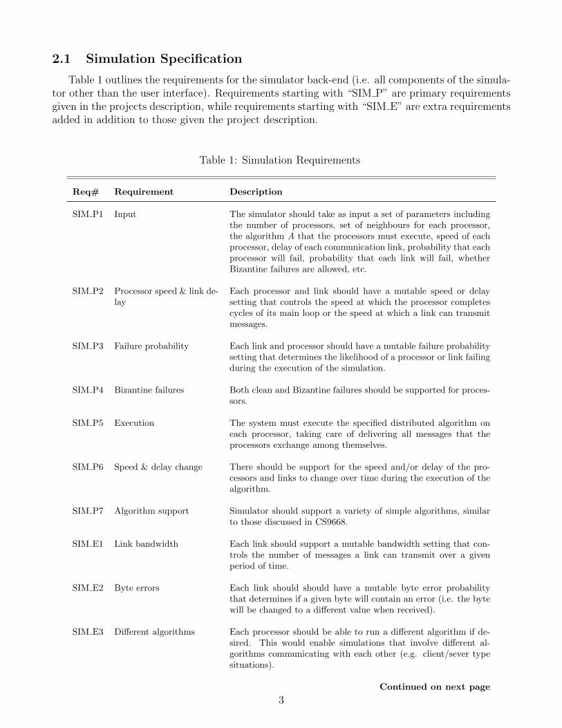
2.1 Simulation Specification
Table 1 outlines the requirements for the simulator back-end (i.e. all components of the simula-tor other than the user interface). Requirements starting with “SIM P” are primary requirementsgiven in the projects description, while requirements starting with “SIM E” are extra requirementsadded in addition to those given the project description.
Table 1: Simulation Requirements
Req# Requirement Description
SIM P1 Input The simulator should take as input a set of parameters includingthe number of processors, set of neighbours for each processor,the algorithm A that the processors must execute, speed of eachprocessor, delay of each communication link, probability that eachprocessor will fail, probability that each link will fail, whetherBizantine failures are allowed, etc.
SIM P2 Processor speed & link de-lay
Each processor and link should have a mutable speed or delaysetting that controls the speed at which the processor completescycles of its main loop or the speed at which a link can transmitmessages.
SIM P3 Failure probability Each link and processor should have a mutable failure probabilitysetting that determines the likelihood of a processor or link failingduring the execution of the simulation.
SIM P4 Bizantine failures Both clean and Bizantine failures should be supported for proces-sors.
SIM P5 Execution The system must execute the specified distributed algorithm oneach processor, taking care of delivering all messages that theprocessors exchange among themselves.
SIM P6 Speed & delay change There should be support for the speed and/or delay of the pro-cessors and links to change over time during the execution of thealgorithm.
SIM P7 Algorithm support Simulator should support a variety of simple algorithms, similarto those discussed in CS9668.
SIM E1 Link bandwidth Each link should support a mutable bandwidth setting that con-trols the number of messages a link can transmit over a givenperiod of time.
SIM E2 Byte errors Each link should should have a mutable byte error probabilitythat determines if a given byte will contain an error (i.e. the bytewill be changed to a different value when received).
SIM E3 Different algorithms Each processor should be able to run a different algorithm if de-sired. This would enable simulations that involve different al-gorithms communicating with each other (e.g. client/sever typesituations).
Continued on next page
3
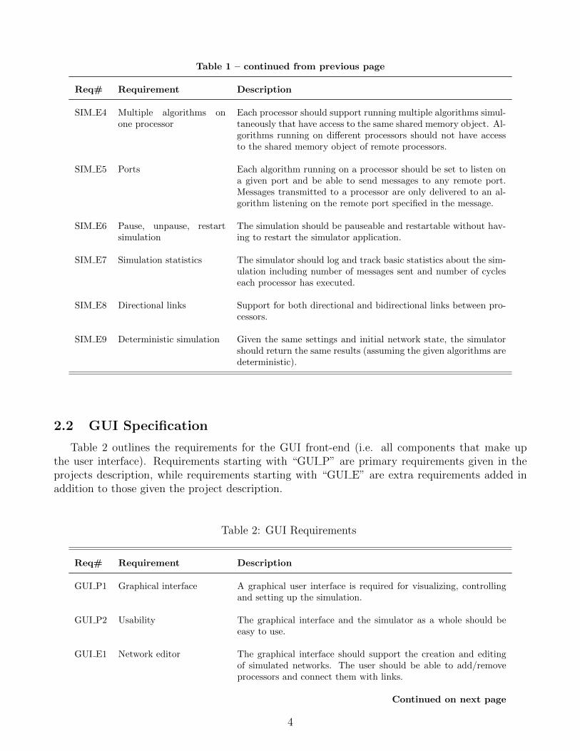
Table 1 – continued from previous page
Req# Requirement Description
SIM E4 Multiple algorithms onone processor
Each processor should support running multiple algorithms simul-taneously that have access to the same shared memory object. Al-gorithms running on different processors should not have accessto the shared memory object of remote processors.
SIM E5 Ports Each algorithm running on a processor should be set to listen ona given port and be able to send messages to any remote port.Messages transmitted to a processor are only delivered to an al-gorithm listening on the remote port specified in the message.
SIM E6 Pause, unpause, restartsimulation
The simulation should be pauseable and restartable without hav-ing to restart the simulator application.
SIM E7 Simulation statistics The simulator should log and track basic statistics about the sim-ulation including number of messages sent and number of cycleseach processor has executed.
SIM E8 Directional links Support for both directional and bidirectional links between pro-cessors.
SIM E9 Deterministic simulation Given the same settings and initial network state, the simulatorshould return the same results (assuming the given algorithms aredeterministic).
2.2 GUI Specification
Table 2 outlines the requirements for the GUI front-end (i.e. all components that make upthe user interface). Requirements starting with “GUI P” are primary requirements given in theprojects description, while requirements starting with “GUI E” are extra requirements added inaddition to those given the project description.
Table 2: GUI Requirements
Req# Requirement Description
GUI P1 Graphical interface A graphical user interface is required for visualizing, controllingand setting up the simulation.
GUI P2 Usability The graphical interface and the simulator as a whole should beeasy to use.
GUI E1 Network editor The graphical interface should support the creation and editingof simulated networks. The user should be able to add/removeprocessors and connect them with links.
Continued on next page
4
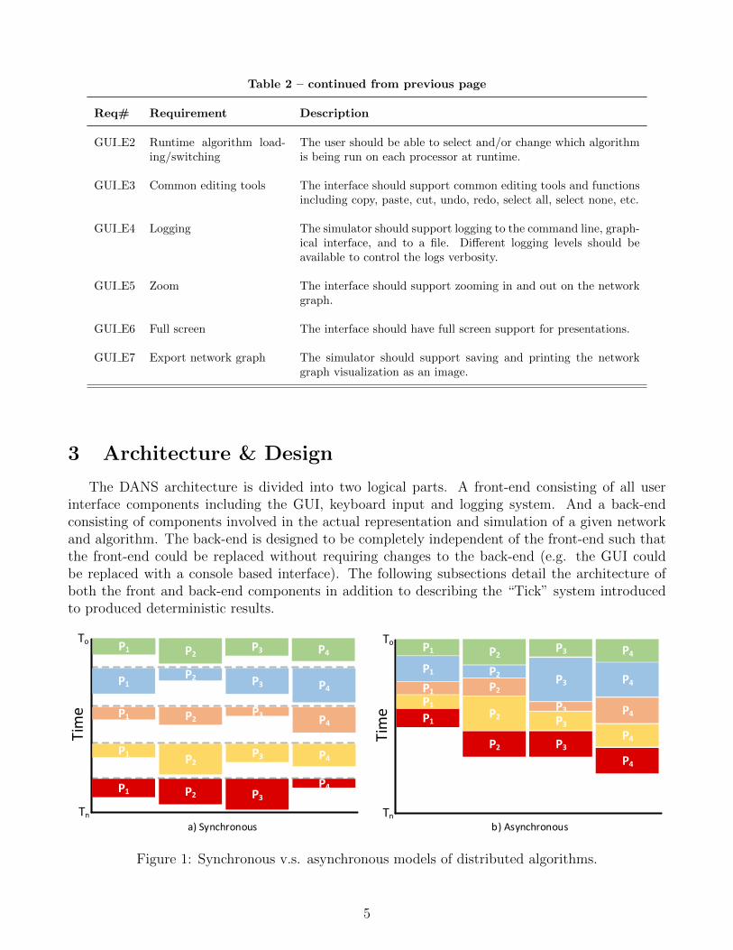
Table 2 – continued from previous page
Req# Requirement Description
GUI E2 Runtime algorithm load-ing/switching
The user should be able to select and/or change which algorithmis being run on each processor at runtime.
GUI E3 Common editing tools The interface should support common editing tools and functionsincluding copy, paste, cut, undo, redo, select all, select none, etc.
GUI E4 Logging The simulator should support logging to the command line, graph-ical interface, and to a file. Different logging levels should beavailable to control the logs verbosity.
GUI E5 Zoom The interface should support zooming in and out on the networkgraph.
GUI E6 Full screen The interface should have full screen support for presentations.
GUI E7 Export network graph The simulator should support saving and printing the networkgraph visualization as an image.
3 Architecture & Design
The DANS architecture is divided into two logical parts. A front-end consisting of all userinterface components including the GUI, keyboard input and logging system. And a back-endconsisting of components involved in the actual representation and simulation of a given networkand algorithm. The back-end is designed to be completely independent of the front-end such thatthe front-end could be replaced without requiring changes to the back-end (e.g. the GUI couldbe replaced with a console based interface). The following subsections detail the architecture ofboth the front and back-end components in addition to describing the “Tick” system introducedto produced deterministic results.
Tim
e
To
Tn
P1 P2 P3 P4
P1P2 P3 P4
P1 P2 P3 P4
P1P2
P3 P4
P1 P2 P3P4
Tim
e
To
Tn
P1 P2 P3 P4P1 P2 P3 P4P1 P2
P3 P4P1
P2 P3P4
P1
P2 P3P4
a) Synchronous b) Asynchronous
Tim
e
To
Tn
P1 P2 P3 P4P1 P2 P3 P4P1 P2
P3 P4P1
P2 P3P4
P1
P2 P3P4
Tim
e
To
Tn
P1 P2 P3 P4P1 P2 P3 P4
P1
P2
P3 P4
P1
P2 P3P4
P1
P2 P3
P4
a) First Execution b ) Second Execution
Ti
Figure 1: Synchronous v.s. asynchronous models of distributed algorithms.
5
3.1 The Tick System
Traditionally, distributed algorithms assume either a synchronous or asynchronous model. Inthe synchronous model (shown in Figure 1.a), it is assumed that each processor pauses afterexecuting a cycle or “round” of the distributed algorithm and waits for all other processors to getto the same point before continuing. Furthermore, the distributed algorithm is broken up into twophases, a message sending phase and a message receiving phase that must occur in the same orderon each processor. This ensures that all messages are sent and received in a given round and thatall processors are executing the same round at the same time. In this way the execution time ofan algorithm can be discussed in terms of rounds (e.g. how many round does an algorithm taketo terminate or what is the state of the network after i rounds).
In the asynchronous model (shown in Figure 1.b), no assumptions are made as to time eachprocessor takes to complete a cycle of the algorithm and no restrictions are placed on when thealgorithm can send or receive messages. In this way each processor immediately starts the nextcycle of its algorithm after completing the last. No guarantee is given that each processor may beexecuting the same cycle of the algorithm or that any message will be sent or received in the same(or any) cycle. In terms of simulation this model can be problematic in that the current state ofthe network at a given time Ti may be different for each execution even if the same initial networkstate and settings are used (as shown in Figure 2). For example, if a given algorithm is executedon 4 processors and each cycle completes at the times shown in Figure 2.a a second execution ofthe same algorithm with the same settings might have different results (in terms of when cyclesstart and end) if an individual processor is delayed for some reason as shown in Figure 2.b. Thiscould happen for a number of reasons including a thread waiting for a resource to unlock or CPUtime being delegated differently on subsequent executions.
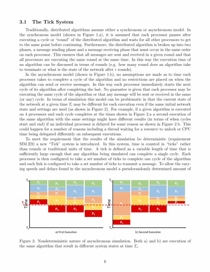
To meet the requirement that the results of the simulation be deterministic (requirementSIM E9) a new “Tick” system is introduced. In this system, time is counted in “ticks” ratherthan rounds or traditional units of time. A tick is defined as a variable length of time that issufficiently large enough that any algorithm being simulated can complete a single cycle. Eachprocessor is then configured to take a set number of ticks to complete one cycle of the algorithmand each link is configured to take a set number of ticks to transmit a message. To allow the vary-ing speeds and delays found in the asynchronous model a pseudorandomly determined amount of
Tim
e
To
Tn
P1 P2 P3 P4
P1P2 P3 P4
P1 P2 P3 P4
P1P2
P3 P4
P1 P2 P3P4
Tim
e
To
Tn
P1 P2 P3 P4P1 P2 P3 P4P1 P2
P3 P4P1
P2 P3P4
P1
P2 P3P4
a) Synchronous b) Asynchronous
Tim
e
To
Tn
P1 P2 P3 P4P1 P2 P3 P4P1 P2
P3 P4P1
P2 P3P4
P1
P2 P3P4
Tim
e
To
Tn
P1 P2 P3 P4P1 P2 P3 P4
P1
P2
P3 P4
P1
P2 P3P4
P1
P2 P3
P4
a) First Execution b ) Second Execution
Ti
Figure 2: Nondeterministic nature of asynchronous simulation. Both a) and b) are execution ofthe same algorithm that result in different system states at time Ti.
6
P3
P1
P4
P2
Tick
0
1
2
3
4
5
P1
P1
P1 P2
P2
P3
P3
P3
P4
P4
Figure 3: Algorithm execution using the Tick system. Only ticks 0 to 5 shown.
change in the speed/delay of each processor/link is allowed. The result remains deterministic asthe seed for the pseudorandom function is provided by the user with the initial settings for thesimulation such that the same changes are applied at the same times for the same seed. This styleof execution is displayed in Figure 3.
DANS supports synchronous3, asynchronous4 and tick based execution. Users are allowed tospecify a minimum tick length such that the length of a tick is:
Max = Maximum time required to complete one cycle of any algorithm being simulated.Min = User define minimum tick speedTick Length = Min if Min > Max else Max
3.2 Simulation Back-End
The main elements of the back-end simulation are the processor, link, message and algorithmobjects. Each of these objects is contained in a single network state object and coordinated by asingle network manager thread. Each algorithm on each processor is contained in its own threadthat is responsible for executing that algorithm. For example if two algorithms are ran on fourprocessors eight threads would be used, one per algorithm per processor. Links are controlled bythe network manager thread which periodically updates each link’s state and ensures its messagesare sent to the correct processor at the correct time. The following subsections detail the designbehind each of these components.
3.2.1 Processors
Processors represent the distributed systems the algorithms will be executed upon and nodesin the network graph. The processor object (shown in Figure 4.b) contains a list of settings andstatistics stored in a concurrent hash map5 indexed by the name of the setting or statistic (i.e.the name is the key of the entry in the hash map). Settings determine how the processor willfunction in the simulation (possible settings are described in Table 7 in Appendix B) and statisticskeep track of various figures related to the execution of the algorithms on the processor during the
3If all processors are given a delay of 1 and links a delay of 0.4If all processors are given a delay of 0.5https://docs.oracle.com/javase/7/docs/api/java/util/concurrent/ConcurrentHashMap.html
7
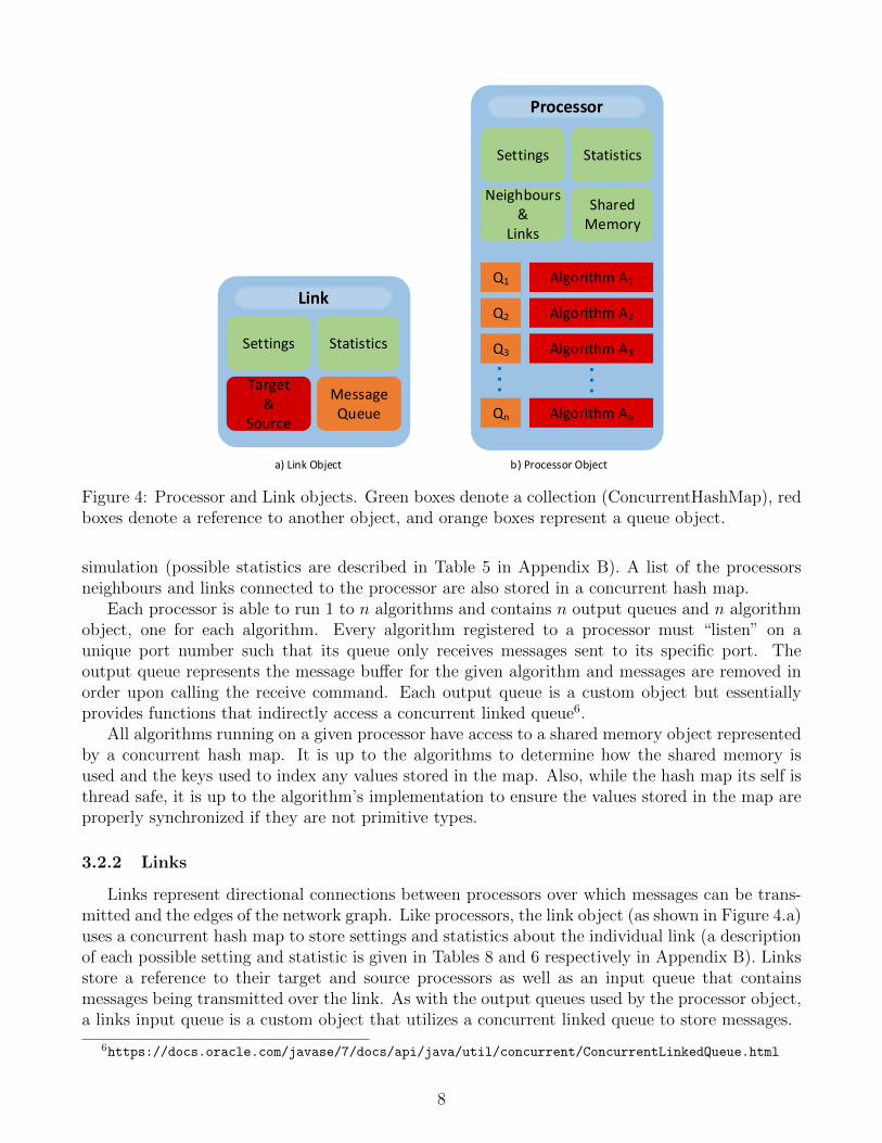
Settings Statistics
SharedMemory
Neighbours&
Links
Processor
Algorithm A1
Algorithm A2
Algorithm A3
Algorithm An
Q1
Q2
Q3
Qn
Link
Settings Statistics
Target&
Source
MessageQueue
a) Link Object b) Processor Object
Figure 4: Processor and Link objects. Green boxes denote a collection (ConcurrentHashMap), redboxes denote a reference to another object, and orange boxes represent a queue object.
simulation (possible statistics are described in Table 5 in Appendix B). A list of the processorsneighbours and links connected to the processor are also stored in a concurrent hash map.
Each processor is able to run 1 to n algorithms and contains n output queues and n algorithmobject, one for each algorithm. Every algorithm registered to a processor must “listen” on aunique port number such that its queue only receives messages sent to its specific port. Theoutput queue represents the message buffer for the given algorithm and messages are removed inorder upon calling the receive command. Each output queue is a custom object but essentiallyprovides functions that indirectly access a concurrent linked queue6.
All algorithms running on a given processor have access to a shared memory object representedby a concurrent hash map. It is up to the algorithms to determine how the shared memory isused and the keys used to index any values stored in the map. Also, while the hash map its self isthread safe, it is up to the algorithm’s implementation to ensure the values stored in the map areproperly synchronized if they are not primitive types.
3.2.2 Links
Links represent directional connections between processors over which messages can be trans-mitted and the edges of the network graph. Like processors, the link object (as shown in Figure 4.a)uses a concurrent hash map to store settings and statistics about the individual link (a descriptionof each possible setting and statistic is given in Tables 8 and 6 respectively in Appendix B). Linksstore a reference to their target and source processors as well as an input queue that containsmessages being transmitted over the link. As with the output queues used by the processor object,a links input queue is a custom object that utilizes a concurrent linked queue to store messages.
6https://docs.oracle.com/javase/7/docs/api/java/util/concurrent/ConcurrentLinkedQueue.html
8
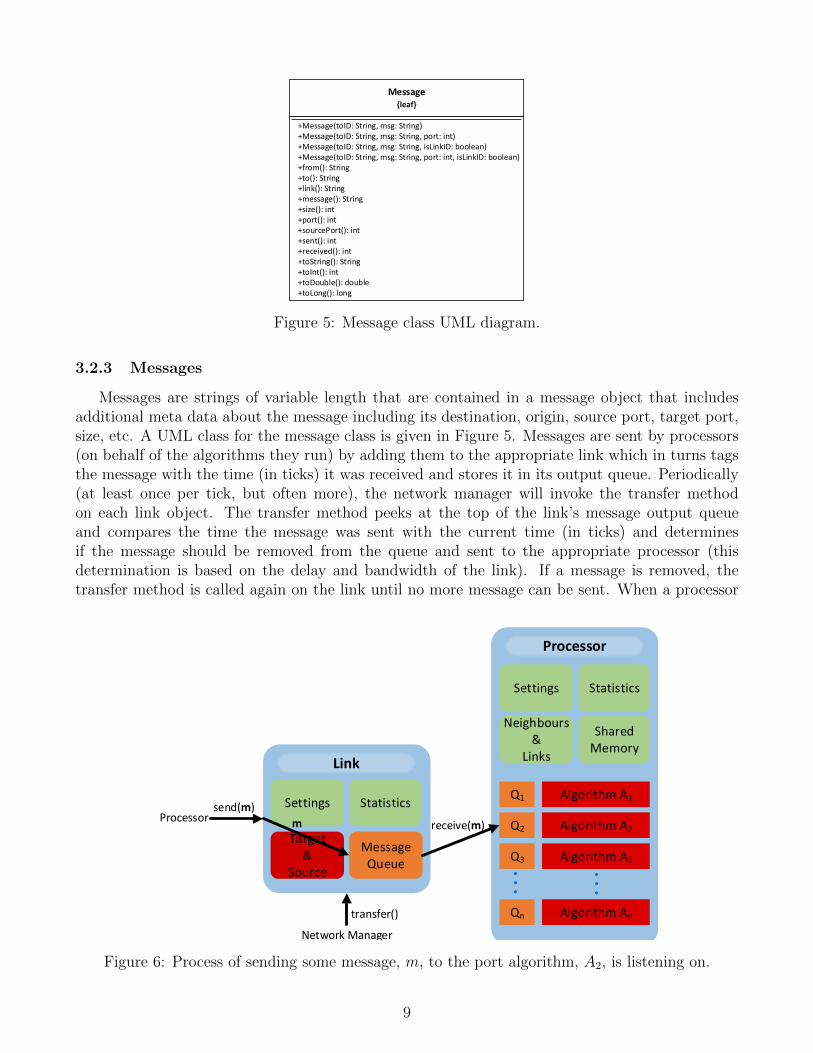
Message{leaf}
+Message(toID: String, msg: String)+Message(toID: String, msg: String, port: int)+Message(toID: String, msg: String, isLinkID: boolean)+Message(toID: String, msg: String, port: int, isLinkID: boolean)+from(): String+to(): String+link(): String+message(): String+size(): int+port(): int+sourcePort(): int+sent(): int+received(): int+toString(): String+toInt(): int+toDouble(): double+toLong(): long
Figure 5: Message class UML diagram.
3.2.3 Messages
Messages are strings of variable length that are contained in a message object that includesadditional meta data about the message including its destination, origin, source port, target port,size, etc. A UML class for the message class is given in Figure 5. Messages are sent by processors(on behalf of the algorithms they run) by adding them to the appropriate link which in turns tagsthe message with the time (in ticks) it was received and stores it in its output queue. Periodically(at least once per tick, but often more), the network manager will invoke the transfer methodon each link object. The transfer method peeks at the top of the link’s message output queueand compares the time the message was sent with the current time (in ticks) and determinesif the message should be removed from the queue and sent to the appropriate processor (thisdetermination is based on the delay and bandwidth of the link). If a message is removed, thetransfer method is called again on the link until no more message can be sent. When a processor
Settings Statistics
SharedMemory
Neighbours&
Links
Processor
Algorithm A1
Algorithm A2
Algorithm A3
Algorithm An
Q1
Q2
Q3
Qn
Link
Settings Statistics
Target&
Source
MessageQueue
Network Manager
Processorsend(m)
transfer()
m receive(m)
Figure 6: Process of sending some message, m, to the port algorithm, A2, is listening on.
9
receives a message from a link it adds it to the queue for the algorithm matching the target portlisted in the message. This process is shown in Figure 6.
3.2.4 Algorithms
Algorithms are user defined programs that have limited access to the simulator back-end andare restricted to only using methods defined in the algorithm class (detailed in Section 4.3). Thealgorithm class isolates algorithms to only accessing elements of the processor they are executedon, enforcing the distributed system model. All algortihms running on the same processor sharethe same settings, statistics and shared memory object. User defined algorithms should containan event loop that receives/sends messages and composes the main logic of the algorithm. Onecycle of this loop will take a specified number of ticks (as defined in the processor’s settings) witha minimum of one cycle per tick.
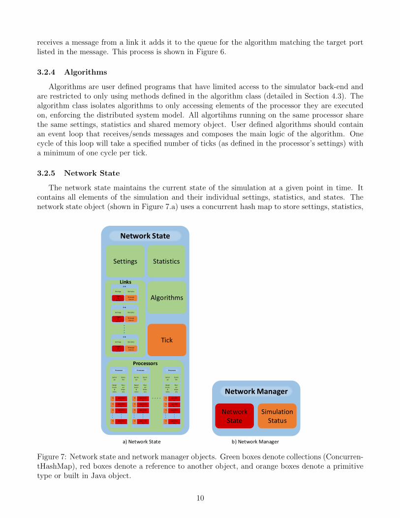
3.2.5 Network State
The network state maintains the current state of the simulation at a given point in time. Itcontains all elements of the simulation and their individual settings, statistics, and states. Thenetwork state object (shown in Figure 7.a) uses a concurrent hash map to store settings, statistics,
Network State
Settin
g s
Sta tis
tics
Sha r
ed
M em
ory
Neig h
bours
&
Link s
Processor
Alg ori thm
A1
Alg ori thm
A2
Alg ori thm
A3
Alg ori thm
An
Q
1
Q
2
Q
3
Q
n
Settin
g s
Sta tis
tics
Sha r
ed
M em
ory
Neig h
bours
&
Link s
Processor
Alg ori thm
A1
Alg ori thm
A2
Alg ori thm
A3
Alg ori thm
An
Q
1
Q
2
Q
3
Q
n
Settin
g s
Sta tis
tics
Sha r
ed
M em
ory
Neig h
bours
&
Link s
Processor
Alg ori thm
A1
Alg ori thm
A2
Alg ori thm
A3
Alg ori thm
An
Q
1
Q
2
Q
3
Q
n
Settings Statistics
Li nk
Settings Sta tistics
Targ et
&
Source
M essa ge
Q ueue
Li nk
Settings Sta tistics
Targ et
&
Source
M essa ge
Q ueue
Li nk
Settings Sta tistics
Targ et
&
Source
M essa ge
Q ueue
Algorithms
Tick
Network Manager
Network State
SimulationStatus
Processors
Links
a) Network State b) Network Manager
Figure 7: Network state and network manager objects. Green boxes denote collections (Concurren-tHashMap), red boxes denote a reference to another object, and orange boxes denote a primitivetype or built in Java object.
10
the set of processors, the set of links and the set of algorithms used in the current simulation. Thesettings and statistic collections contain global properties and defaults that effect or describe thewhole network being simulated (and are described in detail in Appendix B in Tables 4 and 9).The links and processor collections are indexed by the unique identifier assigned to each link andprocessor allowing for efficient lookups. The algorithms collection contains the set of user createdalgorithm classes that have been loaded at run time, indexed by the name of the class. Finallya primitive integer type is used to keep track of the current tick. In addition to the concurrencyprotections offered by the ConcurrentHashMap type, locks are used to ensure that all operationson the network state are thread safe.
3.2.6 Network Manager
The network manager (shown in Figure 7.b) is the main thread of the simulator and is respon-sible for creating, waking and terminating the algorithm threads when appropriate. It contains areference to the network state and the current simulation status (e.g. running, stopped, paused,etc.). Additionally, it is responsible for incrementing the tick value in the network state and period-ically calling the transfer method on each link to ensure messages are delivered to the algorithms’input queues at the correct time (account for the links bandwidth and delay).
3.3 GUI Front-End
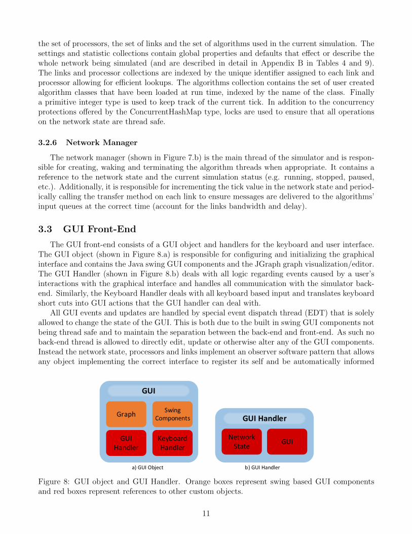
The GUI front-end consists of a GUI object and handlers for the keyboard and user interface.The GUI object (shown in Figure 8.a) is responsible for configuring and initializing the graphicalinterface and contains the Java swing GUI components and the JGraph graph visualization/editor.The GUI Handler (shown in Figure 8.b) deals with all logic regarding events caused by a user’sinteractions with the graphical interface and handles all communication with the simulator back-end. Similarly, the Keyboard Handler deals with all keyboard based input and translates keyboardshort cuts into GUI actions that the GUI handler can deal with.
All GUI events and updates are handled by special event dispatch thread (EDT) that is solelyallowed to change the state of the GUI. This is both due to the built in swing GUI components notbeing thread safe and to maintain the separation between the back-end and front-end. As such noback-end thread is allowed to directly edit, update or otherwise alter any of the GUI components.Instead the network state, processors and links implement an observer software pattern that allowsany object implementing the correct interface to register its self and be automatically informed
GUI
Graph
GUI Handler
Keyboard Handler
SwingComponents GUI Handler
Network State
GUI
a) GUI Object b) GUI Handler
Figure 8: GUI object and GUI Handler. Orange boxes represent swing based GUI componentsand red boxes represent references to other custom objects.
11
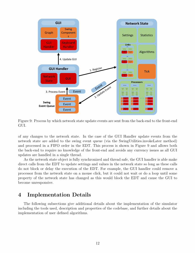
GUI
Graph
GUI Handler
Keyboard Handler
SwingComponent
s
GUI Handler
Network State
GUI
Network State
Settin
g s
Sta tis
tics
Sha r
ed
M em
ory
Neig h
bours
&
Link s
Processor
Alg ori thm
A1
Alg ori thm
A2
Alg ori thm
A3
Alg ori thm
An
Q
1
Q
2
Q
3
Q
n
Settin
g s
Sta tis
tics
Sha r
ed
M em
ory
Neig h
bours
&
Link s
Processor
Alg ori thm
A1
Alg ori thm
A2
Alg ori thm
A3
Alg ori thm
An
Q
1
Q
2
Q
3
Q
n
Settin
g s
Sta tis
tics
Sha r
ed
M em
ory
Neig h
bours
&
Link s
Processor
Alg ori thm
A1
Alg ori thm
A2
Alg ori thm
A3
Alg ori thm
An
Q
1
Q
2
Q
3
Q
n
Settings Statistics
Li nk
Settings Sta tistics
Targ et
&
Source
M essa ge
Q ueue
Li nk
Settings Sta tistics
Targ et
&
Source
M essa ge
Q ueue
Li nk
Settings Sta tistics
Targ et
&
Source
M essa ge
Q ueue
Algorithms
Tick
Processors
Links
Event
Event
Event
Event3. Process Event
4. Update GUI
Swing Event Queue
Figure 9: Process by which network state update events are sent from the back-end to the front-endGUI.
of any changes to the network state. In the case of the GUI Handler update events from thenetwork state are added to the swing event queue (via the SwingUtilities.invokeLater method)and processed in a FIFO order in the EDT. This process is shown in Figure 9 and allows boththe back-end to require no knowledge of the front-end and avoids any currency issues as all GUIupdates are handled in a single thread.
As the network state object is fully synchronized and thread safe, the GUI handler is able makedirect calls from the EDT to update settings and values in the network state so long as these callsdo not block or delay the execution of the EDT. For example, the GUI handler could remove aprocessor from the network state on a mouse click, but it could not wait or do a loop until someproperty of the network state has changed as this would block the EDT and cause the GUI tobecome unresponsive.
4 Implementation Details
The following subsections give additional details about the implementation of the simulatorincluding the tools used, description and properties of the codebase, and further details about theimplementation of user defined algorithms.
12

55.3%
32.0%8.4%
3.7%0.6%
GUI Front-EndSimulation Back-EndAlgorithms
UtilsMisc.
Figure 10: Physical executable lines of code per component.
4.1 Tools & Libraries
The simulator back and front-ends are implemented in Java 8 and is not backwards compatiblewith older versions of Java. The GUI front-end uses the built in swing widget toolkit for creatingGUI elements and utilizes the JGraphX7 library for graph visualization and editing. Several classesfrom the JGraphX library are extended to provide additional features or changes required for thesimulator. Extended classes include mxCell, mxConnectPreview, mxGraph and mxGraphLayout.Finally, toolbar and menu icons from the Java Look-and-Feel Graphics Repository (JLFGR)8
library are also used in the GUI.
4.2 Codebase
The simulator codebase is divided into four parts, the GUI front-end (package dans.GUI ), thesimulation back-end (package dans.network), utilities (package dans.util) and algorithms (packagedans.algorithm). Packages dans.GUI and dans.network contain the front and back-end compo-nents as described in the previous sections. Package dans.util contains utility classes that providesimple services for the other packages (including a logging service). Package dans.algorithm con-tains the abstract algorithm class for users to extend (as described in Section 4.3) as well as several
7https://github.com/jgraph/jgraphx8http://www.oracle.com/technetwork/java/index-138612.html
Table 3: Codebase Metrics
Metric Count
Source Files 54Directories 8Lines of Code 10715Blank Lines of Code 1635Physical Executable Lines of Code 7933Logical Executable Lines of Code 6253
13

Algorithm{abstract}
+getID(): String {leaf}+getPort(): int {leaf}+send(msg: Message): boolean {leaf}+receive(wait: boolean): Message {leaf}+getNeighbors(): String[] {leaf}+getLinks(): String[] {leaf}+print(text: String) {leaf}+display(text: String) {leaf}+doMainLoop(): boolean {leaf}+terminate() {leaf}+algorithm(): Object {abstract}...
Figure 11: UML class diagram for abstract algorithm class. Some methods omitted for spacereasons.
example algorithms. A break down of the number of executable lines of code per division is givenin Figure 10 and overall counts are given in Table 3.
4.3 Algorithm Creation
As described in Section 3.2.4 users may create algorithms by extending the abstract Algorithmclass (UML diagram shown in Figure 11). This class provides methods that grant limited accessto the properties of the processor the algorithm is executed on as well as the ability to sendand receive messages. All user created algorithms should follow the template given in Listing 1,such that they contain a single event loop in the algorithm method that handles the sending andreceiving of all messages. This loop should run until the value of doMainLoop() returns false or thealgorithm has finished running (it is acceptable to break or return out of the loop if the algorithmshould terminate). The algorithm method may return a single value that represents the result of
Listing 1: Algorithm Template1 import dans.algorithm.Algorithm;
2 import dans.algorithm.Message;
3
4 public class MyAlgorithm extends Algorithm {
5
6 @Override
7 public Object algorithm () {
8 //Do algorithm setup here9
10 while(doMainLoop ()) {
11 //Main algorithm code12 //Break, return, or call terminate() when done13 }
14
15 //Code to run before termination16 return MyResults;
17 }
18 }
14
the execution which is displayed when the processor terminates.A receive method is provided that will either immediately return the next message in the input
queue (or null) or wait for the next message to arrive depending on the arguments given. If thealgorithm waits for a message it will not block the execution of any other algorithm (i.e. the otheralgorithms running will not wait for it to finish its cycle before continuing and the tick value willbe incremented normally). The send method returns a boolean value indicating if the messagewas added to the links output queue successfully and will return immediately in either case (i.e.the send method does not wait for the message to be delivered).
Complete documentation of the Algorithm and Message classes are given in the JavaDoc foundat http://cs1.ca/cs9668/async. Example algorithms for leader election, broadcasting, anddoing simple calculations using a BFS tree are given in Appendix C.
5 Conclusion
DANS provides a simple and easy to use network simulator for visualizing and prototypingbasic distributed algorithms that is aimed at educational use. While both traditional synchronousand asynchronous modes of operation are supported (by configuring the delays in a certain wayas described in Section 3.1) a new Tick based system is introduced that allows for deterministicresults while maintaining most properties of an asynchronous simulation. A detailed description ofthe DANS architecture and design is given as well as details about the Java based implementation.Additional documentation for the simulator can be found in the Appendixes (including examplealgorithms) and complete documentation of the Algorithm and Message classes (the two classesusers would interact with) can be found at http://cs1.ca/cs9668/async.
There are a number of directions for future work beyond simply fixing the known bugs andlimitations listed in Appendix D. Some possible features include adding support for wireless net-works, increasing the realism of the simulation (e.g. more closely modelling the OSI layers), addingmore network editing tools, adding additional simulation statistics, allowing for editing while thesimulation is paused, adding addtional documentation and examples, automatic generation of dif-ferent kinds of networks, automatic randomization of processor and link settings and support forautomatic network graph layouts.
15
References
[1] Srinivasan Keshav. REAL: A network simulator. University of California, 1988.
[2] Steven McCanne and Sally Floyd. Ns network simulator, 1995.
[3] Network Simulator. ns-2. http://www.isi.edu/nsnam/ns/, 1989.
[4] Thomas R Henderson, Mathieu Lacage, George F Riley, C Dowell, and JB Kopena. Networksimulations with the ns-3 simulator. SIGCOMM demonstration, 15:17, 2008.
[5] George F Riley. The georgia tech network simulator. In Proceedings of the ACM SIGCOMMworkshop on Models, methods and tools for reproducible network research, pages 5–12. ACM,2003.
[6] Riverbed Technology. Riverbed modeler. http://www.riverbed.com/
products/performance-management-control/network-performance-management/
network-simulation.html.
[7] Andras Varga et al. The omnet++ discrete event simulation system. In Proceedings of theEuropean simulation multiconference (ESM2001), volume 9, page 65. sn, 2001.
[8] Tetcos. Netsim. http://tetcos.com/, 2002.
[9] Michael J Fischer, Nancy A Lynch, and Michael S Paterson. Impossibility of distributedconsensus with one faulty process. Journal of the ACM (JACM), 32(2):374–382, 1985.
[10] Ion Stoica, Robert Morris, David Karger, M Frans Kaashoek, and Hari Balakrishnan. Chord:A scalable peer-to-peer lookup service for internet applications. ACM SIGCOMM ComputerCommunication Review, 31(4):149–160, 2001.
16
Appendix
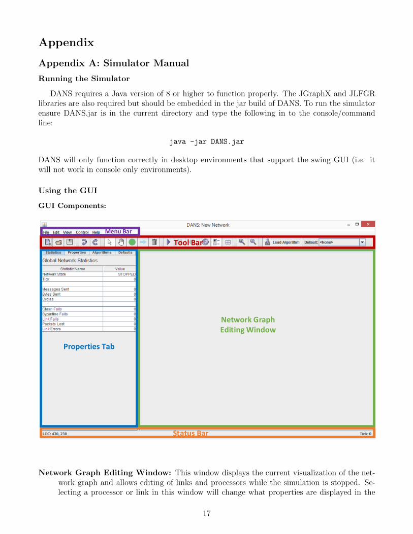
Appendix A: Simulator Manual
Running the Simulator
DANS requires a Java version of 8 or higher to function properly. The JGraphX and JLFGRlibraries are also required but should be embedded in the jar build of DANS. To run the simulatorensure DANS.jar is in the current directory and type the following in to the console/commandline:
java -jar DANS.jar
DANS will only function correctly in desktop environments that support the swing GUI (i.e. itwill not work in console only environments).
Using the GUI
GUI Components:
Network Graph Editing Window
Properties Tab
Tool Bar
Status Bar
Menu Bar
Network Graph Editing Window: This window displays the current visualization of the net-work graph and allows editing of links and processors while the simulation is stopped. Se-lecting a processor or link in this window will change what properties are displayed in the
17
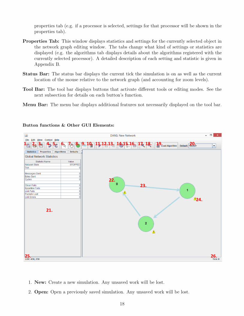
properties tab (e.g. if a processor is selected, settings for that processor will be shown in theproperties tab).
Properties Tab: This window displays statistics and settings for the currently selected object inthe network graph editing window. The tabs change what kind of settings or statistics aredisplayed (e.g. the algorithms tab displays details about the algorithms registered with thecurrently selected processor). A detailed description of each setting and statistic is given inAppendix B.
Status Bar: The status bar displays the current tick the simulation is on as well as the currentlocation of the mouse relative to the network graph (and accounting for zoom levels).
Tool Bar: The tool bar displays buttons that activate different tools or editing modes. See thenext subsection for details on each button’s function.
Menu Bar: The menu bar displays additional features not necessarily displayed on the tool bar.
Button functions & Other GUI Elements:
1. 2. 3. 4. 5. 6. 7. 8. 9. 10. 11.12.13. 14.15.16. 17. 18. 19. 20.
21.
25. 26.
22.23.
24.
1. New: Create a new simulation. Any unsaved work will be lost.
2. Open: Open a previously saved simulation. Any unsaved work will be lost.
18

3. Save: Save the current simulation to a file.
4. Undo: Undo the last network graph editing action (does not effect settings changed in theproperties tab).
5. Redo: Redo the last network graph editing action (does not effect settings changed in theproperties tab).
6. Selection: Activates the selection editing mode. In the selection editing mode, clicking ona processor or link will select them and allow you to hold down the mouse button to movethe object.
7. Pan: Activates the panning editing mode. If the network graph is zoomed in to the pointthat scroll bars are shown, the panning editing mode will allow you to move your view of thegraph. This has no effect if the scroll bars are not shown.
8. Add Processor: Activates the processor editing mode. In this editing mode clicking in anyblank space in the network graph editing window will create a processor.
9. Add Link: Activates the link editing mode. In this editing mode clicking on a processorwill allow you to create a link to the processor that is clicked next. Clicking on a blank spacewill remove the incomplete link.
10. Delete: Activates the delete editing mode. Any processor or link clicked on while in thisediting mode will be deleted.
11. Play: Start the simulation. While the simulation is running most editing features will bedisabled.
12. Pause: Pause the currently running simulation. A simulation must be paused before it canbe restarted.
13. Restart: If the simulation has terminated or is currently paused you may restart the sim-ulation. Restarting the simulation will return the simulation to an editable state like it wasbefore the play button was pressed. A running simulation must be paused before it may berestarted.
14. Toggle Log: Display or hide the logging window.
15. Toggle Properties: Display or hide the properties tab.
16. Toggle Grid: Display or hide the grid.
17. Zoom In: Zoom in on the network graph.
18. Zoom Out: Zoom out on the network graph.
19. Load Algorithm: Displays a file chooser window so that you can select an algorithm toload. The first time an algorithm is loaded it is automatically set as the default algorithm.
19
20. Select Default Algorithm: Sets the default algorithm for processors to run. When se-lected, all algorithms registered as listening on the default port are changed to the selecteddefault algorithm and processors created in the future will have the default algorithm regis-tered on the default port.
21. Properties Tab: See Appendix B for details on the settings and statistics displayed in theproperties tab.
22. Processor: Circles in the network graph editing window represent processors. Processorsthat are green are in an OK or running state. Processors that are red are terminated and/orhave encountered an exception. Processors that are orange have experienced a failure asa result of the failure probability setting in the processor’s settings. Double clicking on aprocessor will allow you to edit its current ID.
23. Link: Arrows in the network graph editing window represent links between processors.Links that are blue are in an OK or not transmitting state. Links that are green are activelytransmitting a message that should be displayed in text beside the link (blue text for messagesgoing into the link and green for messages leaving it). Links that are orange have experienceda failure as a result of the failure probability setting in the link’s settings. Clicking on eitherend of a link will allow you to drag it to a new processor to reassign it.
24. Warning: A flashing yellow exclamation mark icon indicates that an algorithm has not yetbeen assigned to the processor. If the simulation is run without assigning an algorithm to aprocessor, the processor will terminate immediately.
25. Mouse Location: The current mouse location relative to the network graph (accountingfor zoom levels).
26. Tick: The current tick value of the simulation.
Keyboard Shortcuts:
Delete: Delete the currently selected object in the network graph editing window.
Ctrl-a: Select all objects in the network graph editing window.
Ctrl-d: Select none.
Ctrl-x: Cut.
Ctrl-c: Copy.
Ctrl-p: Paste.
Ctrl-=: Zoom in.
Ctrl–: Zoom out.
=: Reset zoom.
Ctrl-z: Undo.
20
Ctrl-y: Redo.
F1: Selection edit mode.
F2: Pan edit mode.
F3: Processor edit mode.
F4: Link edit mode.
F5: Delete edit mode.
F12: Toggle fullscreen mode.
21
Appendix B: Properties Tab Settings & Statistics
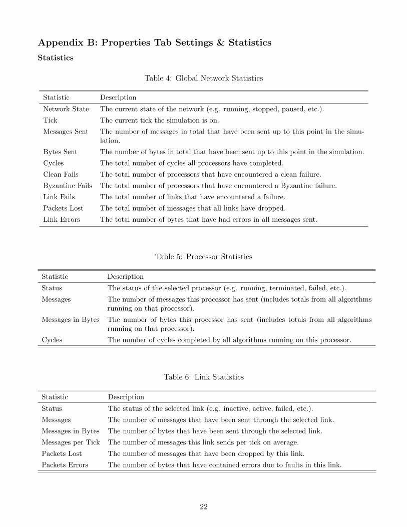
Statistics
Table 4: Global Network Statistics
Statistic Description
Network State The current state of the network (e.g. running, stopped, paused, etc.).
Tick The current tick the simulation is on.
Messages Sent The number of messages in total that have been sent up to this point in the simu-lation.
Bytes Sent The number of bytes in total that have been sent up to this point in the simulation.
Cycles The total number of cycles all processors have completed.
Clean Fails The total number of processors that have encountered a clean failure.
Byzantine Fails The total number of processors that have encountered a Byzantine failure.
Link Fails The total number of links that have encountered a failure.
Packets Lost The total number of messages that all links have dropped.
Link Errors The total number of bytes that have had errors in all messages sent.
Table 5: Processor Statistics
Statistic Description
Status The status of the selected processor (e.g. running, terminated, failed, etc.).
Messages The number of messages this processor has sent (includes totals from all algorithmsrunning on that processor).
Messages in Bytes The number of bytes this processor has sent (includes totals from all algorithmsrunning on that processor).
Cycles The number of cycles completed by all algorithms running on this processor.
Table 6: Link Statistics
Statistic Description
Status The status of the selected link (e.g. inactive, active, failed, etc.).
Messages The number of messages that have been sent through the selected link.
Messages in Bytes The number of bytes that have been sent through the selected link.
Messages per Tick The number of messages this link sends per tick on average.
Packets Lost The number of messages that have been dropped by this link.
Packets Errors The number of bytes that have contained errors due to faults in this link.
22
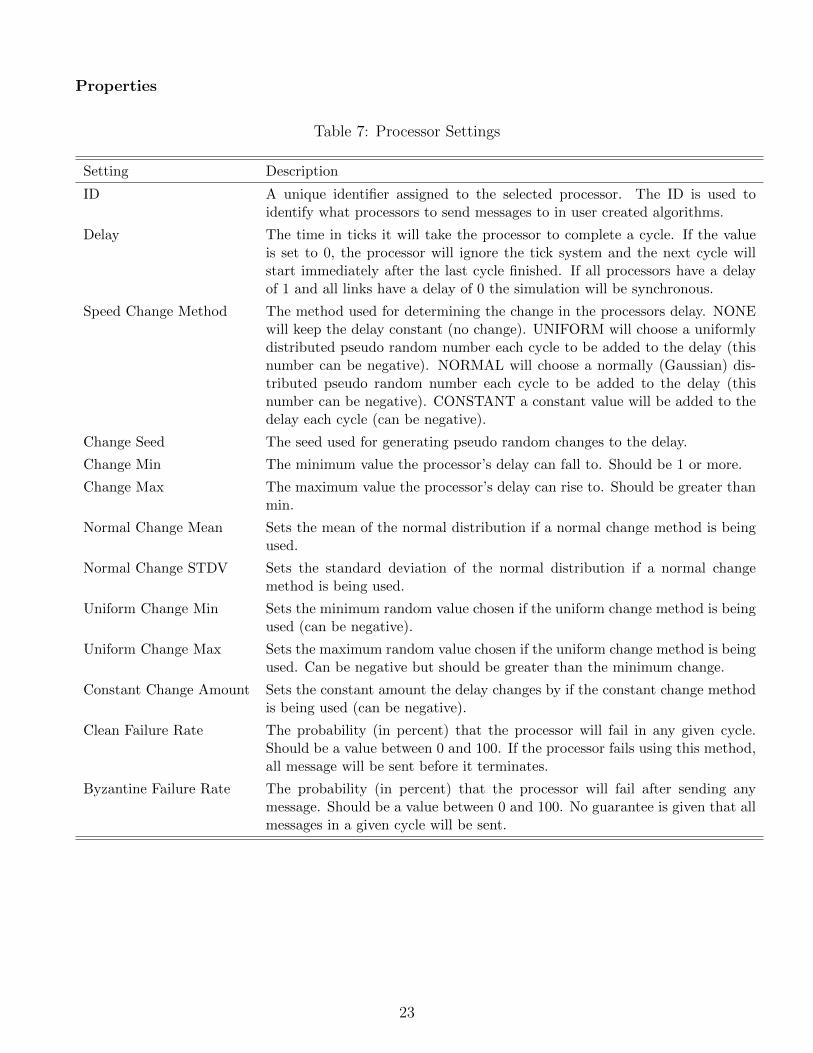
Properties
Table 7: Processor Settings
Setting Description
ID A unique identifier assigned to the selected processor. The ID is used toidentify what processors to send messages to in user created algorithms.
Delay The time in ticks it will take the processor to complete a cycle. If the valueis set to 0, the processor will ignore the tick system and the next cycle willstart immediately after the last cycle finished. If all processors have a delayof 1 and all links have a delay of 0 the simulation will be synchronous.
Speed Change Method The method used for determining the change in the processors delay. NONEwill keep the delay constant (no change). UNIFORM will choose a uniformlydistributed pseudo random number each cycle to be added to the delay (thisnumber can be negative). NORMAL will choose a normally (Gaussian) dis-tributed pseudo random number each cycle to be added to the delay (thisnumber can be negative). CONSTANT a constant value will be added to thedelay each cycle (can be negative).
Change Seed The seed used for generating pseudo random changes to the delay.
Change Min The minimum value the processor’s delay can fall to. Should be 1 or more.
Change Max The maximum value the processor’s delay can rise to. Should be greater thanmin.
Normal Change Mean Sets the mean of the normal distribution if a normal change method is beingused.
Normal Change STDV Sets the standard deviation of the normal distribution if a normal changemethod is being used.
Uniform Change Min Sets the minimum random value chosen if the uniform change method is beingused (can be negative).
Uniform Change Max Sets the maximum random value chosen if the uniform change method is beingused. Can be negative but should be greater than the minimum change.
Constant Change Amount Sets the constant amount the delay changes by if the constant change methodis being used (can be negative).
Clean Failure Rate The probability (in percent) that the processor will fail in any given cycle.Should be a value between 0 and 100. If the processor fails using this method,all message will be sent before it terminates.
Byzantine Failure Rate The probability (in percent) that the processor will fail after sending anymessage. Should be a value between 0 and 100. No guarantee is given that allmessages in a given cycle will be sent.
23
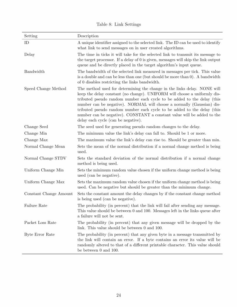
Table 8: Link Settings
Setting Description
ID A unique identifier assigned to the selected link. The ID can be used to identifywhat link to send messages on in user created algorithms.
Delay The time in ticks it will take for the selected link to transmit its message tothe target processor. If a delay of 0 is given, messages will skip the link outputqueue and be directly placed in the target algorithm’s input queue.
Bandwidth The bandwidth of the selected link measured in messages per tick. This valueis a double and can be less than one (but should be more than 0). A bandwidthof 0 disables restricting the links bandwidth.
Speed Change Method The method used for determining the change in the links delay. NONE willkeep the delay constant (no change). UNIFORM will choose a uniformly dis-tributed pseudo random number each cycle to be added to the delay (thisnumber can be negative). NORMAL will choose a normally (Gaussian) dis-tributed pseudo random number each cycle to be added to the delay (thisnumber can be negative). CONSTANT a constant value will be added to thedelay each cycle (can be negative).
Change Seed The seed used for generating pseudo random changes to the delay.
Change Min The minimum value the link’s delay can fall to. Should be 1 or more.
Change Max The maximum value the link’s delay can rise to. Should be greater than min.
Normal Change Mean Sets the mean of the normal distribution if a normal change method is beingused.
Normal Change STDV Sets the standard deviation of the normal distribution if a normal changemethod is being used.
Uniform Change Min Sets the minimum random value chosen if the uniform change method is beingused (can be negative).
Uniform Change Max Sets the maximum random value chosen if the uniform change method is beingused. Can be negative but should be greater than the minimum change.
Constant Change Amount Sets the constant amount the delay changes by if the constant change methodis being used (can be negative).
Failure Rate The probability (in percent) that the link will fail after sending any message.This value should be between 0 and 100. Messages left in the links queue aftera failure will not be sent.
Packet Loss Rate The probability (in percent) that any given message will be dropped by thelink. This value should be between 0 and 100.
Byte Error Rate The probability (in percent) that any given byte in a message transmitted bythe link will contain an error. If a byte contains an error its value will berandomly altered to that of a different printable character. This value shouldbe between 0 and 100.
24
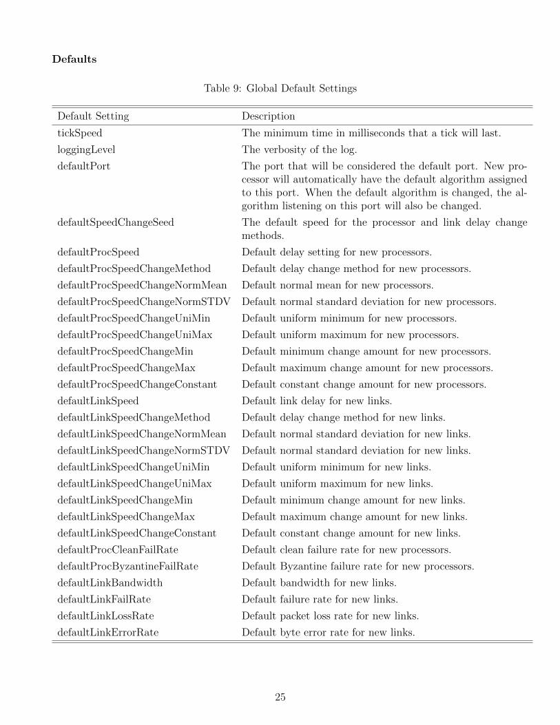
Defaults
Table 9: Global Default Settings
Default Setting Description
tickSpeed The minimum time in milliseconds that a tick will last.
loggingLevel The verbosity of the log.
defaultPort The port that will be considered the default port. New pro-cessor will automatically have the default algorithm assignedto this port. When the default algorithm is changed, the al-gorithm listening on this port will also be changed.
defaultSpeedChangeSeed The default speed for the processor and link delay changemethods.
defaultProcSpeed Default delay setting for new processors.
defaultProcSpeedChangeMethod Default delay change method for new processors.
defaultProcSpeedChangeNormMean Default normal mean for new processors.
defaultProcSpeedChangeNormSTDV Default normal standard deviation for new processors.
defaultProcSpeedChangeUniMin Default uniform minimum for new processors.
defaultProcSpeedChangeUniMax Default uniform maximum for new processors.
defaultProcSpeedChangeMin Default minimum change amount for new processors.
defaultProcSpeedChangeMax Default maximum change amount for new processors.
defaultProcSpeedChangeConstant Default constant change amount for new processors.
defaultLinkSpeed Default link delay for new links.
defaultLinkSpeedChangeMethod Default delay change method for new links.
defaultLinkSpeedChangeNormMean Default normal standard deviation for new links.
defaultLinkSpeedChangeNormSTDV Default normal standard deviation for new links.
defaultLinkSpeedChangeUniMin Default uniform minimum for new links.
defaultLinkSpeedChangeUniMax Default uniform maximum for new links.
defaultLinkSpeedChangeMin Default minimum change amount for new links.
defaultLinkSpeedChangeMax Default maximum change amount for new links.
defaultLinkSpeedChangeConstant Default constant change amount for new links.
defaultProcCleanFailRate Default clean failure rate for new processors.
defaultProcByzantineFailRate Default Byzantine failure rate for new processors.
defaultLinkBandwidth Default bandwidth for new links.
defaultLinkFailRate Default failure rate for new links.
defaultLinkLossRate Default packet loss rate for new links.
defaultLinkErrorRate Default byte error rate for new links.
25
Appendix C: Example Algorithms
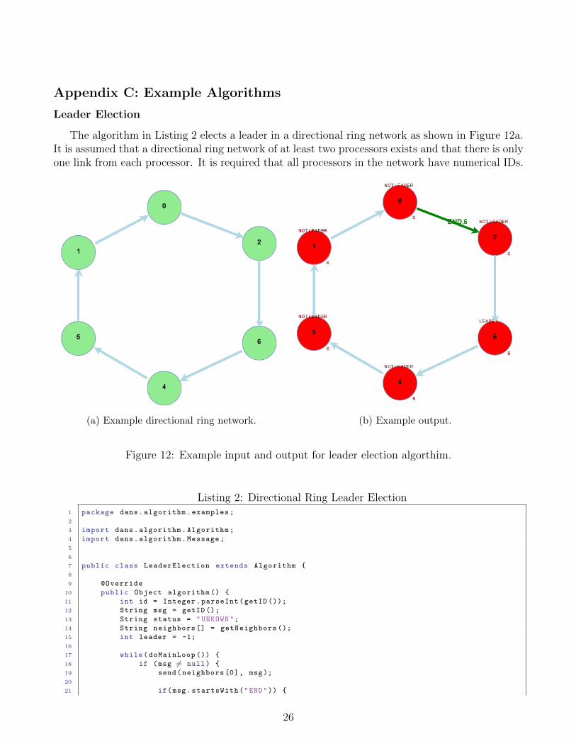
Leader Election
The algorithm in Listing 2 elects a leader in a directional ring network as shown in Figure 12a.It is assumed that a directional ring network of at least two processors exists and that there is onlyone link from each processor. It is required that all processors in the network have numerical IDs.
(a) Example directional ring network. (b) Example output.
Figure 12: Example input and output for leader election algorthim.
Listing 2: Directional Ring Leader Election1 package dans.algorithm.examples;
2
3 import dans.algorithm.Algorithm;
4 import dans.algorithm.Message;
5
6
7 public class LeaderElection extends Algorithm {
8
9 @Override
10 public Object algorithm () {
11 int id = Integer.parseInt(getID ());
12 String msg = getID ();
13 String status = "UNKOWN";
14 String neighbors [] = getNeighbors ();
15 int leader = -1;
16
17 while(doMainLoop ()) {
18 if (msg 6= null) {
19 send(neighbors [0], msg);
20
21 if(msg.startsWith("END")) {
26

22 return leader;
23 }
24 }
25
26 msg = null;
27
28 Message m = receive(false);
29 if(m 6= null) {
30 if(m.message (). startsWith("END")) {
31 leader = Integer.parseInt(m.message (). split(",")[1]);
32
33 if(neighbors [0]. equals(leader+"")) {
34 return leader;
35 } else {
36 msg = m.message ();
37 }
38 } else {
39 int i = m.toInt ();
40 if(i > id) {
41 status = "NOT LEADER";
42 msg = m.message ();
43 } else if(id > i) {
44 msg = null;
45 } else {
46 leader = Integer.parseInt(getID ());
47 status = "LEADER";
48 msg = "END ," + leader;
49 }
50 }
51 }
52
53 display(status );
54 }
55
56 return leader;
57 }
58
59 }
27
Bidirectional Leader Election
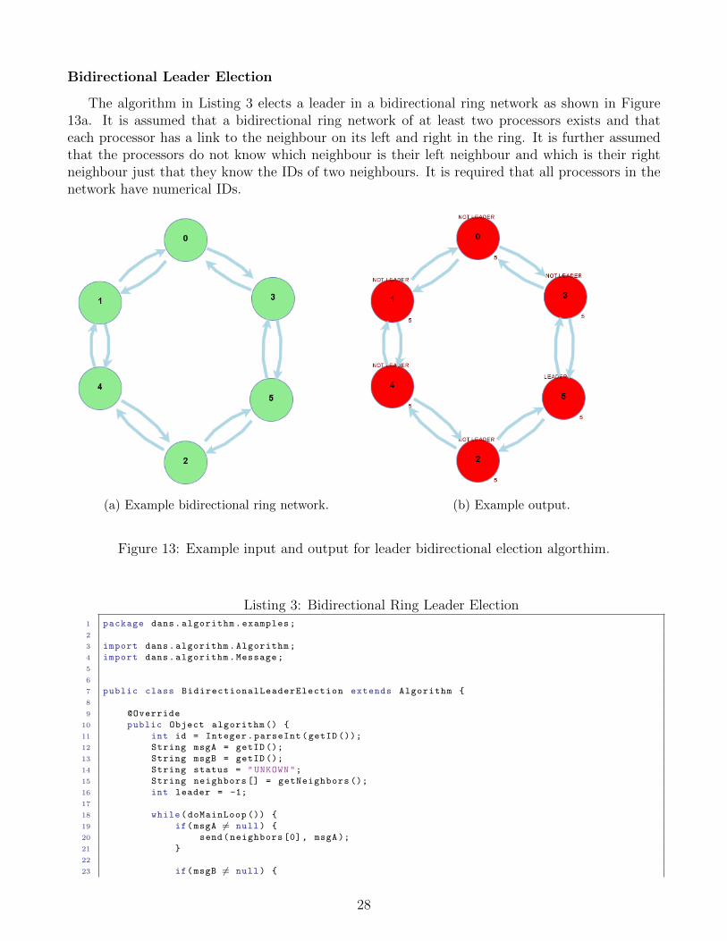
The algorithm in Listing 3 elects a leader in a bidirectional ring network as shown in Figure13a. It is assumed that a bidirectional ring network of at least two processors exists and thateach processor has a link to the neighbour on its left and right in the ring. It is further assumedthat the processors do not know which neighbour is their left neighbour and which is their rightneighbour just that they know the IDs of two neighbours. It is required that all processors in thenetwork have numerical IDs.
(a) Example bidirectional ring network. (b) Example output.
Figure 13: Example input and output for leader bidirectional election algorthim.
Listing 3: Bidirectional Ring Leader Election1 package dans.algorithm.examples;
2
3 import dans.algorithm.Algorithm;
4 import dans.algorithm.Message;
5
6
7 public class BidirectionalLeaderElection extends Algorithm {
8
9 @Override
10 public Object algorithm () {
11 int id = Integer.parseInt(getID ());
12 String msgA = getID ();
13 String msgB = getID ();
14 String status = "UNKOWN";
15 String neighbors [] = getNeighbors ();
16 int leader = -1;
17
18 while(doMainLoop ()) {
19 if(msgA 6= null) {
20 send(neighbors [0], msgA);
21 }
22
23 if(msgB 6= null) {
28

24 send(neighbors [1], msgB);
25 }
26
27 if(leader >= 0) {
28 return leader;
29 }
30
31 msgA = null;
32 msgB = null;
33
34 Message in;
35 while((in = receive ()) 6= null) {
36 String m = in.message ();
37 String from = in.from ();
38 String splited [] = m.split(",");
39
40 if(m.startsWith("END")) {
41 leader = Integer.parseInt(splited [1]);
42
43 if(from.equals(neighbors [0])) {
44 if(leader == Integer.parseInt(neighbors [1])) return leader;
45 msgB = m;
46 } else {
47 if(leader == Integer.parseInt(neighbors [0])) return leader;
48 msgA = m;
49 }
50 } else {
51 int i = in.toInt ();
52
53 if(i > id) {
54 status = "NOT LEADER";
55
56 if(from.equals(neighbors [0])) {
57 msgB = m;
58 } else {
59 msgA = m;
60 }
61 } else if(i == id) {
62 status = "LEADER";
63 leader = id;
64 msgA = "END ," + id;
65 }
66 }
67
68 display(status );
69 }
70 }
71
72 return leader;
73 }
74
75 }
29
Broadcast
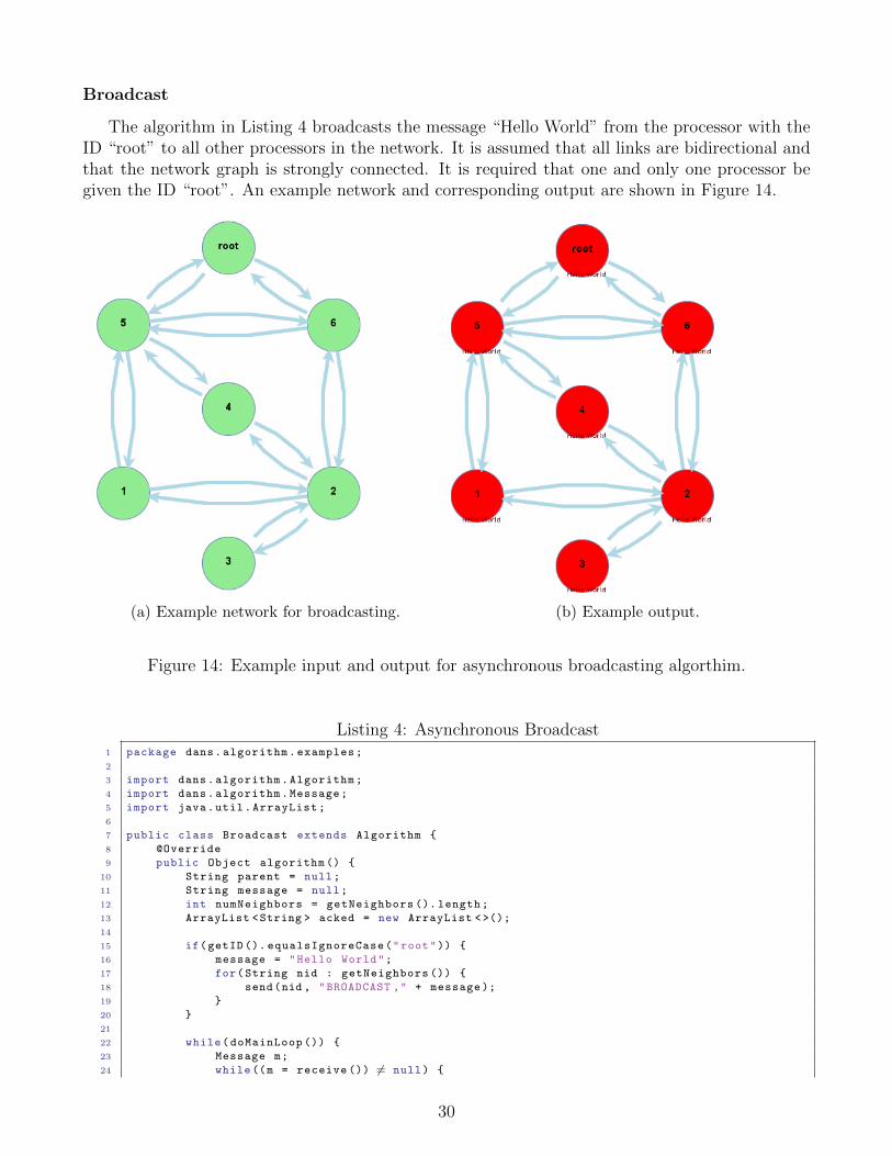
The algorithm in Listing 4 broadcasts the message “Hello World” from the processor with theID “root” to all other processors in the network. It is assumed that all links are bidirectional andthat the network graph is strongly connected. It is required that one and only one processor begiven the ID “root”. An example network and corresponding output are shown in Figure 14.
(a) Example network for broadcasting. (b) Example output.
Figure 14: Example input and output for asynchronous broadcasting algorthim.
Listing 4: Asynchronous Broadcast1 package dans.algorithm.examples;
2
3 import dans.algorithm.Algorithm;
4 import dans.algorithm.Message;
5 import java.util.ArrayList;
6
7 public class Broadcast extends Algorithm {
8 @Override
9 public Object algorithm () {
10 String parent = null;
11 String message = null;
12 int numNeighbors = getNeighbors (). length;
13 ArrayList <String > acked = new ArrayList <>();
14
15 if(getID (). equalsIgnoreCase("root")) {
16 message = "Hello World";
17 for(String nid : getNeighbors ()) {
18 send(nid , "BROADCAST ," + message );
19 }
20 }
21
22 while(doMainLoop ()) {
23 Message m;
24 while((m = receive ()) 6= null) {
30

25 if(m.message (). startsWith("BROADCAST ,")) {
26 if(message == null) {
27 message = m.message (). split(",")[1];
28 parent = m.from ();
29 for(String nid : getNeighbors ()) {
30 if(!nid.equals(parent )) {
31 send(nid , m.message ());
32 }
33 }
34 } else {
35 send(m.from(),"ACK");
36 }
37 } else if(m.message (). equals("ACK")) {
38 acked.add(m.from ());
39 }
40 }
41
42 if(getID (). equalsIgnoreCase("root")) {
43 if(acked.size() >= numNeighbors) {
44 return message;
45 }
46 } else {
47 if(parent 6= null && acked.size() >= numNeighbors - 1) {
48 send(parent , "ACK");
49 return message;
50 }
51 }
52
53 }
54
55 return message;
56 }
57
58 }
31
Largest ID
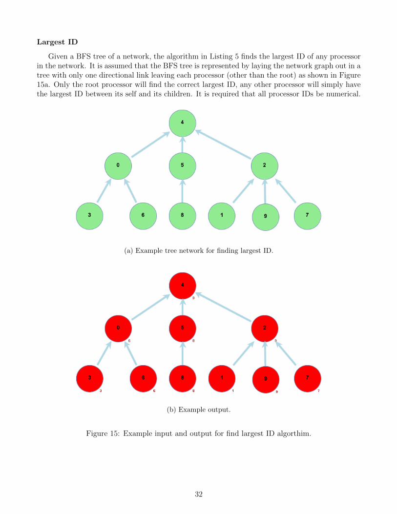
Given a BFS tree of a network, the algorithm in Listing 5 finds the largest ID of any processorin the network. It is assumed that the BFS tree is represented by laying the network graph out in atree with only one directional link leaving each processor (other than the root) as shown in Figure15a. Only the root processor will find the correct largest ID, any other processor will simply havethe largest ID between its self and its children. It is required that all processor IDs be numerical.
(a) Example tree network for finding largest ID.
(b) Example output.
Figure 15: Example input and output for find largest ID algorthim.
32
Listing 5: Find Largest ID1 package dans.algorithm.examples;
2
3 import dans.algorithm.Algorithm;
4 import dans.algorithm.Message;
5
6
7 public class TreeLargestID extends Algorithm {
8
9 @Override
10 public Object algorithm () {
11 String parents [] = getNeighbors ();
12 String childern [] = getSources ();
13 int id = Integer.parseInt(getID ());
14 String msg = null;
15 int largest = id;
16 int heardfrom = 0;
17
18
19 if(childern.length == 0) {
20 msg = getID ();
21 } else if(parents.length == 0 && childern.length == 0) {
22 return largest;
23 }
24
25 while(doMainLoop ()) {
26 if(msg 6= null) {
27 for(String pid : parents) {
28 send(new Message(pid , msg ));
29 }
30
31 return largest;
32 }
33
34 msg = null;
35
36 Message in;
37 while((in = receive ()) 6= null) {
38 int i = in.toInt ();
39
40 if(i > largest) {
41 largest = i;
42 }
43
44 heardfrom ++;
45 }
46
47 if(heardfrom >= childern.length) {
48 msg = largest + "";
49 }
50 }
51
52 return largest;
53 }
54
55 }
33
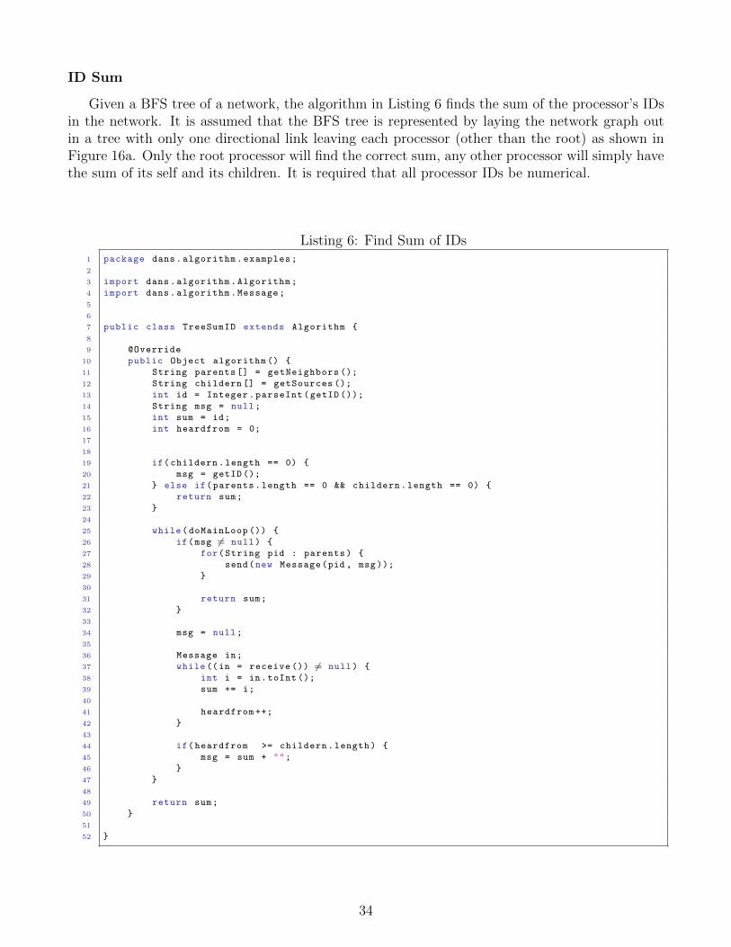
ID Sum
Given a BFS tree of a network, the algorithm in Listing 6 finds the sum of the processor’s IDsin the network. It is assumed that the BFS tree is represented by laying the network graph outin a tree with only one directional link leaving each processor (other than the root) as shown inFigure 16a. Only the root processor will find the correct sum, any other processor will simply havethe sum of its self and its children. It is required that all processor IDs be numerical.
Listing 6: Find Sum of IDs1 package dans.algorithm.examples;
2
3 import dans.algorithm.Algorithm;
4 import dans.algorithm.Message;
5
6
7 public class TreeSumID extends Algorithm {
8
9 @Override
10 public Object algorithm () {
11 String parents [] = getNeighbors ();
12 String childern [] = getSources ();
13 int id = Integer.parseInt(getID ());
14 String msg = null;
15 int sum = id;
16 int heardfrom = 0;
17
18
19 if(childern.length == 0) {
20 msg = getID ();
21 } else if(parents.length == 0 && childern.length == 0) {
22 return sum;
23 }
24
25 while(doMainLoop ()) {
26 if(msg 6= null) {
27 for(String pid : parents) {
28 send(new Message(pid , msg ));
29 }
30
31 return sum;
32 }
33
34 msg = null;
35
36 Message in;
37 while((in = receive ()) 6= null) {
38 int i = in.toInt ();
39 sum += i;
40
41 heardfrom ++;
42 }
43
44 if(heardfrom >= childern.length) {
45 msg = sum + "";
46 }
47 }
48
49 return sum;
50 }
51
52 }
34

(a) Example tree network for finding the sum of IDs.
(b) Example output.
Figure 16: Example input and output for find sum of IDs algorthim.
35
Appendix D: Known Bugs & Limitations
Know Bugs:
1. Adding two or more links between two processors in the same direction will cause a displaybug in which a “loop” will be created in the edge connecting the processors. This has noeffect on the simulation.
2. If two processors share a bidirectional link (a link in both directions) and one of the linksis dragged to a new processor a display issue can occur in which the edges are not drawncorrectly. Moving the processor will fix the issue. This has no effect on the simulation.
3. The print function does not correctly size the network graph to the paper it is printed onand can be cut off or sized incorrectly.
4. In some cases when in full screen mode the file chooser and other dialogue boxes are notshown. Algorithms should be loaded before entering fullscreen mode.
5. The properties tab only allows integers to be input for a processor’s ID. It should allow anyunique string. A work around is to set the processor’s ID by double clicking on it in thenetwork editor window.
6. Some keyboard shortcuts that should be disable are still enabled while running the simulation.
Know Limitations:
1. Only processors can be copied, cut or and pasted.
2. Undo/redo only work on changes to the network graph. They do not undo/redo changes tosettings or properties.
3. The simulation visualization can only display a certain number of messages per tick. Ifmultiple messages are sent down the same link during the same tick, not all will be displayed.This has no effect on the actual simulation.
4. If the display command is called multiple times in one tick, only the most recent text will bedisplayed. This has no effect on the actual simulation.
5. Panning only works if scroll bars are displayed in the network graph editing window (i.e.when the windowed is zoomed in on the graph).
6. Having a large number of processors send many messages every tick will cause the GUI tobecome unresponsive or even crash.
7. Statistics are combined for all algorithms running on the same processor, there is currentlyno way to view per algorithm statistics.
8. No distinction is made in the visualization between messages sent on different ports. Ifmultiple algorithms on the same processor are running simultaneously and sending messagesdown the same link on the same tick, not all messages will be displayed (though they will besent, just not shown).
9. Link IDs can not be changed after they are created.
36