simulation study of microwave microplasmas …...simulation study of microwave microplasmas based on...
TRANSCRIPT

Simulation Study of Microwave
Microplasmas based on
Microstrip Technology
Lizhu Tong
Keisoku Engineering System Co., Ltd., Japan
October 15, 2015
Keisoku Engineering System Co., Ltd., 1-9-5 Uchikanda, Chiyoda-ku, Tokyo 101-0047, Japan. TEL:+81-3-5282-7040 FAX:+81-3-5282-0808 http://www.kesco.co.jp/

The generation of stable plasmas can be easily done using microwave generators. A
large number of chemical processes make use of such plasma sources.
The physics of a microwave plasma is quite different depending on whether the TE
mode (out-of-plane electric field) or the TM mode (in-plane electric field) is
propagating. In both cases it is not possible for the electromagnetic wave to
penetrate into regions of the plasma where the electron density exceeds the critical
electron density (around 7.6x10¹⁶ /m3 for argon at 2.45 GHz).
The pressure range for microwave plasmas is very broad. For electron cyclotron
resonance (ECR) plasmas, the pressure can be on the order of 1 Pa or less. For
non-ECR plasmas the pressure typically ranges from 100 Pa up to atmospheric
pressure.
The power can range from a few watts to several kilowatts. Microwave plasmas are
popular due to the cheap availability of microwave power.
2
Research Backgrounds (1)

Microstrip microplasmas utilize the microstrip technology
to transfer electromagnetic fields into a small gas gap in
order to generate microplasma.
A typical schematic diagram of a split-ring resonator
microplasma source is shown in the right figure.
A low-power microwave plasma device based on a
metallic wave-guiding structure on a fused-silica wafer
with a small gas channel inside is shown as follows
3
Research Backgrounds (2)
1) F. Iza and J.A. Hopwood, IEEE
Trans. Plasma Sci. 31(4), 2003,
782.
2) A.R. Hoskinson, et al., J. Anal.
At. Spectrom. 26, 2011, 1258.
1) U. Engel, et al., Anal. Chem. 72,
2000, 193.
2) A.M. Bilgic, et al., Plasma Sources
Sci. Technol. 9, 2000, 1.
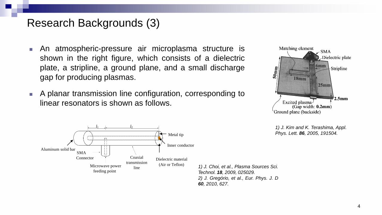
An atmospheric-pressure air microplasma structure is
shown in the right figure, which consists of a dielectric
plate, a stripline, a ground plane, and a small discharge
gap for producing plasmas.
A planar transmission line configuration, corresponding to
linear resonators is shown as follows.
4
Research Backgrounds (3)
1) J. Kim and K. Terashima, Appl.
Phys. Lett. 86, 2005, 191504.
1) J. Choi, et al., Plasma Sources Sci.
Technol. 18, 2009, 025029.
2) J. Gregório, et al., Eur. Phys. J. D
60, 2010, 627.
SMA
Connector Coaxial
transmission
line
Dielectric material
(Air or Teflon)
Inner conductorAluminum solid bar
Microwave power
feeding point
l1 l2
Metal tip

Research Backgrounds (4)
5
High-density 3D microwave microstrip plasmas
When the plasma density is equal to the critical electron density, the electro-
magnetic wave transitions from being propagating to evanescent within a resonance
zone. The critical electron density is given by the formula:
At a frequency of 2.45 GHz, this corresponds to an electron density of 7.6×10¹⁶ /m3,
which is lower than most industrial applications.
𝑛𝑒 =𝜖0𝑚𝑒𝜔
2
𝑒2
This work

Computational Method by using COMSOL (1)
6
The plasma characteristics on the microwave time scale are separated from the longer term
plasma behavior, which is governed by the ambipolar fields.
Maxwell’s equations
𝛻 × 𝐄 = −𝜕𝐁
𝜕𝑡𝛻 × 𝐇 = 𝐉𝑝 +
𝜕𝐃
𝜕𝑡𝑱𝑝 = 𝜎𝑬
𝜎 =𝑛𝑒𝑒
2
𝑚𝑒(𝜈𝑚 + 𝑗𝜔
Plasma conductivity
In the Plasma Module, the electromagnetic waves are computed in the Frequency Domain.
𝛻 × 𝜇−1𝛻 × 𝐄 = 𝜔2𝜖0𝜖𝑟 − 𝑗𝜔𝜎 𝐄
Plasma current density

Computational Method by using COMSOL (2)
7
The power transferred from the electromagnetic fields to the electrons is calculated by
𝑄𝑟ℎ =1
2real(𝐉 ∙ 𝐄∗
In addition to the electromagnetic waves, the electron density, electron energy density, plasma
potential, ionic and neutral species as well as electric field are solved in the Time Domain.
𝑒 = −𝑛𝑒 𝜇𝑒𝐄 − 𝐷𝑒𝛻𝑛𝑒
Electron transport
𝜕
𝜕𝑡𝑛𝑒 + 𝛻 ∙ 𝑒 = 𝑅𝑒
𝜕
𝜕𝑡𝑛𝜀 + 𝛻 ∙ 𝜀 + 𝐄 ∙ 𝑒 = 𝑅𝜀
𝜀 = −𝑛𝜀 𝜇𝜀𝐄 − 𝐷𝜀𝛻𝑛𝜀
Source term 𝑅𝑒 =
𝑗=1
𝑀
𝑥𝑗𝑘𝑗𝑁𝑛𝑛𝑒 𝑅𝜀 =
𝑗=1
𝑃
𝑥𝑗𝑘𝑗𝑁𝑛𝑛𝑒∆휀𝑗

Computational Method by using COMSOL (3)
8
Modified Maxwell-Stefan equation for ion and neutral species
Reaction rate 𝑘𝑗 = 𝛾 0
∞
휀𝜎𝑗 휀 𝑓 휀 𝑑휀 𝛾 = (2𝑞/𝑚 1/2
Cross sections for electron collisions
𝜌𝜕
𝜕𝑡𝑤𝑘 + 𝜌(𝐮 ∙ 𝛻 𝑤𝑘 = 𝛻 ∙ 𝐣𝑘 + 𝑅𝑘
𝐣𝑘 = 𝜌𝜔𝑘𝐕𝑘 𝐕𝑘 =
𝑗=1
𝑄
𝐷𝑘𝑗𝐝𝑘 −𝐷𝑘
𝑇
𝜌𝜔𝑘𝛻𝑙𝑛𝑇
𝐝𝑘 =1
𝑐𝑅𝑇𝛻𝑝𝑘 − 𝜔𝑘𝛻𝑝 − 𝜌𝑘𝐠𝑘 + 𝜔𝑘
𝑗=1
𝑄
𝜌𝑗𝐠𝒋
Poisson's equation is solved in order to compute the ambipolar electric field generated by the
separation of charges:
𝜌 = 𝑞
𝑘=1
𝑁
𝑍𝑘𝑛𝑘 − 𝑛𝑒−𝛻 ∙ 휀0휀𝑟𝛻𝑉 = 𝜌

Computational Method by using COMSOL (4)
In the TE mode, the high frequency electric field only contains an out-of-plane component and
electrons do not experience any change in the high frequency electric field during the
microwave time scale.
The TM/TEM mode causes in-plane motion of the electrons on the microwave time scale, so in
regions where the high frequency electric field is significant, this destroys the phase coherence
between the electrons and the fields, causing the electrons to gain energy.
9

Computational Method by using COMSOL (5)
The resonance zone that the electromagnetic wave transitions from being propagating to
evanescent, can be smoothed by activating the Compute tensor plasma conductivity checkbox
in the Plasma Properties section:
𝜈𝑚 = 𝜈𝑒 + 𝜈eff
The Doppler broadening parameter
𝜈eff = 𝜔 𝛿
The effective collision frequency
10

11
3D Model of Microwave Microstrip Plasma Source (1)
substrate
microstrip
air
gas channel
coaxial
connector
Based on the microstrip technology, the microwave power can be directed to the target area
precisely, so as to allow the generation of high-density plasmas and reduce the contamination
of the plasma source by sputtering electrodes.
Computational conditions:
⦁ Gases:Argon
⦁ Species: 𝑒−, Ar, Ar+, Ar2+, Ar*, Ar2
*
⦁ Microwave frequency:2.45 GHz
⦁ Input power:2 W
⦁ Temperature:300 K
⦁ Gas pressure: 50, 100 Torr
⦁ Diameter of gas channel: 0.9 mm
⦁ The effective collision frequency: 𝜔 20
1) A.M. Bilgiç, et al J. Anal. At. Spectrom.
15, 2000, 579.

12
No. Reaction Reaction type Reaction rate
(cm3s-1 / cm6s-1 / s-1)
1
2
3
4
5
6
7
8
9
10
11
12
13
14
15
𝑒− + Ar 𝑒− + Ar
𝑒− + Ar 𝑒− + Ar∗
𝑒− + Ar 2𝑒− + Ar+
𝑒− + Ar∗ 2𝑒− + Ar+
𝑒− + Ar∗ 𝑒− + Ar
𝑒− + Ar+ Ar∗
2𝑒− + Ar+ Ar∗ + 𝑒−
𝑒− + Ar2+ Ar∗ + Ar
2Ar∗ Ar+ + Ar + 𝑒−
2Ar2∗ Ar2
+ + 2Ar + 𝑒−
Ar∗ + 2Ar Ar2∗ + Ar
Ar+ + 2Ar Ar2+ + Ar
Ar2∗ 2Ar
𝑒− + Ar2∗ 2𝑒− + Ar2
+
𝑒− + Ar2∗ 𝑒− + 2Ar
Elastic scattering
Excitation
Ionization
Step-wise Ionization
Metastable quenching
Recombination
Recombination
Recombination
Penning ionization
Penning ionization
Excitation transfer
Charge exchange
De-excitation
Step-wise Ionization
De-excitation
4.0 × 10⁻¹³𝑇𝑒−0.5
5.0 × 10⁻²⁷𝑇𝑒−4.5
5.38 × 10⁻⁸𝑇𝑒−0.66
5.0 × 10⁻¹⁰
5.0 × 10⁻¹⁰
1.14 × 10⁻³²
2.5 × 10⁻³¹
6.0 × 10⁷
9.0 × 10⁻⁸𝑇𝑒0.7exp(−3.66/𝑇𝑒
10−7
Chemical reactions in the model
3D Model of Microwave Microstrip Plasma Source (2)

13
Electric field Electron density
Electron temperature Electric potential
3D Model of Microwave Microstrip Plasma Source (3)
Gas pressure: 50 Torr

14
Argon ion density
Electrical conductivity
Ar+
Ar2+ Critical electron density
3D Model of Microwave Microstrip Plasma Source (4)
Gas pressure: 50 Torr

15
Excited argon density
Collisional power loss
3D Model of Microwave Microstrip Plasma Source (5)
Ar*
Ar2*
Gas pressure: 50 Torr

16
3D Model of Microwave Microstrip Plasma Source (6)
Electric field Electron density
Electron temperature Electric potential
Gas pressure: 100 Torr

17
3D Model of Microwave Microstrip Plasma Source (7)
Gas pressure: 100 Torr
Critical electron density
Argon ion density
Electrical conductivity
Ar+
Ar2+

This paper presents a three-dimensional fluid model for a low-power microwave-excited
argon microstrip plasma source operated at 2.45 GHz.
The resonance zone at which the electron density is equal to the critical density is
solved by adding an effective collision frequency to the momentum collision frequency.
It is shown that the microwave power is directed to the gas channel. The electric field
induced by the electromagnetic wave is concentrated in the neighborhood of the inner
surface of gas channel under the microstrip line.
The governed ions are atomic argon ions (Ar+) and molecular argon ions (Ar2+) and the
latter has a wider distribution.
The model proposed in this work is expected to have the potentiality to develop various
microwave-excited microstrip plasma sources.
Conclusions
18

Thank you for your attention !
Questions & Comments ?
Tokyo