simulation of ic engines with special focus on spray ... · simulation of ic engines with special...
TRANSCRIPT
IOSR Journal of Mechanical and Civil Engineering (IOSR-JMCE)
e-ISSN: 2278-1684,p-ISSN: 2320-334X, Volume 12, Issue 3 Ver. III (May. - Jun. 2015), PP 15-27 www.iosrjournals.org
DOI: 10.9790/1684-12331527 www.iosrjournals.org 15 | Page
Simulation of IC Engines with Special Focus on Spray Models of
CI Engines
M Suresh1, Dr. R. Hari Prakash
2, Dr. B Durga Prasad
3
1Asso. Prof. & Head, Dept. of Mechanical Engineering, GKCE, Sullurpet, INDIA 2Principal, Jagan’s College of Engineering & Technology, Nellore, INDIA
3Prof. & Head, Department of Mechanical Engineering, JNTUACE, Anantapuramu, INDIA
Abstract : Spark ignited and Compression ignited internal combustion engines are the two types under the
classification of IC engines based on ignition mechanism. In spark ignited IC engines the pressurized air fuel
mixture will be given the spark ignition in the chamber just after sufficient fraternization where as in
compression ignited IC engines the pressurized air gets ignited of the fuel spray in the chamber. In spark ignited
engines, a carburetor may be used where the fuel and air gets mixed and the resulting mixture will be supplied
to the chamber, or electronic controlled mechanism may be used where based on the load and required speed
the concentration of fuel in the mixture will be varied whereas it is usually fixed in the carburetor based
systems. In compression ignited engines, the spraying mechanism is crucial for satisfactory combustion. The
injector may be moved toward the chamber and in the reverse direction. The number of nozzles and the angle of
injection of fuel may be varied. In this paper, the above described phenomena are modeled and results are compared.
Keywords - air-fuel mixture, nozzle, injector, bowl axis.
I. Introduction According to history engines that may be internal combustion or external combustion are said to be
designed to avoid the man and animal based transport system. Nowadays, these engines can drive large sized
transportation systems like naval, air-based as well as turbo-charged roadway vehicles even with miniaturized designs of engine. Most of the transportation vehicles use either the spark ignited or compression ignited
versions of internal combustion engines. But each of the types suffers from some limitations. Subsequently
many hybrid engines are designed and some are in design phase [1-3].
A number of variations of spark ignited and compression ignited IC engines are proposed in the
literature. In [4], supercomputing applications in IC engines are introduced. Results of three example cases are
presented. The cases include motoring flow in a pent-roof engine, charge distribution in a DISC engine, and
coherent flamelet combustion model. In [5], the importance of homogeneous charge compression ignition
combustion of an IC engine was stated elaborately. The combustion mode transition problem of a multi-cylinder
IC engine was studied. The proposed control strategies are validated using Hardware-in-the-loop simulations.
Engine thermal management was considered in [6]. The potential of manipulating combustion wall
temperature for improving engine efficiency was demonstrated. The results show that optimized combustion
wall temperature produces significant fuel consumption improvements at low to medium engine speed at both low and high load. In [7], the development of a homogeneous charge compression ignition free-piston engine-
compressor was presented. Modeling of CI engine for control was proposed in [8]. Advanced CI engine was
proposed in [9]. A CI engine for straight plant oil fuelling was presented in [10].A five-stroke engine was
proposed in [11]. A review of gasoline direct compression ignition engine was presented in [12]. A non-linear
model of SI engine for controller design was proposed in [13]. Sectional combustion chamber base SI engine
was proposed in [14].
The combustion in IC engine is crucial for generating mechanical work out of the chemical energy. The
combustion in spark ignited engines is homogeneous because of two reasons. One is the characteristics of fuel,
the second the time available for the fuel to mix with the air. In compression ignited engine the case is different.
The combustion is non-homogeneous because of the same reasons. In this paper, the spark ignited and
compression ignited engines are studied, compared and simulated by considering different variations of the two. The rest of the paper is organized as follows. The next section deals with the features, operation, simulation and
modeling of SI engine. The section III, considers the operation and modeling of CI engine. The section IV
compares the SI and CI engines with the simulation results generated in sections II and III. Section V concludes
the paper.

Simulation of IC Engines with special focus on Spray models of CI Engines
DOI: 10.9790/1684-12331527 www.iosrjournals.org 16 | Page
II. Simulation of SI Engine The early spark ignited internal combustion engines have a carburetor. The carburetor is responsible to
mix the fuel with air to prepare the fuel-air mixture. The spark ignited engines usually take Gasoline as fuel. The
gasoline is a transparent, petroleum-derived liquid obtained by fractional distillation of petroleum. The gasoline
is a high-volatile fuel and has high self-ignition temperature. The carburetor based engines mix the gasoline with
air in a specific predefined ratio, before the time. The mixture will be extracted by the piston downward
movement initiated by the external motor. The mixture will be entered into the chamber and then the intake
valve gets closed. By the upward movement of the piston the mixture of fuel and air gets pressurized. Because
of high volatile-ness and sufficient time for the fuel to get mingled with air homogeneous combustion is possible
in the spark ignited engines. The compression ratio is usually set in the range of 6:1 to 10:1.
The mixture consists of air and gasoline. The chemical reaction during the combustion follows 2 C8 H18 + 25 O2 16 CO2 + 18 H2O (1)
The C8 H18 corresponds to the gasoline and O2 the air. The carbon dioxide and water vapor gets out of the
chamber through exhaust valve during exhaust stroke. In carburetor based spark ignited engines the air-fuel ratio
is fixed throughout the life of the engine. If some more energy output is required, throttling will be used. During
throttling, the air-fuel ratio will be changed slightly, around 2% of its original value. For example, if the original
air-fuel ratio is 12, then during a maximum throttling an air-fuel ratio of 11.76 may be obtained. This is done by
increasing the fuel content in the mixture. Now the simulation results of a model of SI engine with carburetor
will be presented. The specifications of the engine are given below.
Working Cycle: Four Stroke Cycle,
Fuel and Method of Injection: Petrol, SI, Carburation Number of Cylinders: 1
Cooling System: Liquid Cooling
Cylinder Bore: 150mm, Piston Stroke: 180mm, Nominal Engine Speed: 1400rpm, Compression Ratio: 9,
Cylinder Head Design: Two valves
With the above specifications the engine was simulated and obtained the performance measures which
are publicly available at the link http://www.fast-files.com/getfile.aspx?file=92759. The key parameters of the
above engine simulation are tabulated in the table I.
Table I: Key parameters of Carburetor based SI Engine
Piston Engine Power 34.422 KW
Mechanical Efficiency 0.80592
Air-fuel equivalence ratio 1
Thermal Efficiency 0.30006
Brake Specific Fuel Consumption 0.27267 kg/kWh
Fraction of wet NOx in exh. Gas 5437.0 ppm
Specif. NOx emis. reduc. to NO2 40.233 g/KWh
Specific SO2 emission 0.0000 g/KWh
Brake Mean Effective Pressure 9.2757 bar
Indicated Mean Effective Pressure 11.509 bar
Volumetric Efficiency 0.91401
Maximum cylinder pressure 63.8 bar
In carburetor based SI engines, the compression ratio is fixed at a predefined value. Even when the load
varies the work that will be produced is almost the same. During throttling a little improvement of work
delivered is possible around the predefined work. In practice, because of different use of a vehicle, different loads may be driven by similar engines. But the work delivered even with variety of loads is almost same in the
carburetor based SI engines. This is the major limitation of carburetor based SI engines. If the load of the engine
can be sensed, the fuel-air ratio of the mixture may be varied to drive variety of loads by a single design.
Electronic sensors are available in the market which has highest grade of accuracy and ease of implementation.
The application of electronic sensing equipment overruled the carburetor based SI engines more than few
decades ago. Using the data from the load sensors, the fuel-air ratio will be varied to drive smoothly the sensed
load. This kind of spark ignited IC engines is referred as port based SI engine.
Simulation of IC Engines with special focus on Spray models of CI Engines
DOI: 10.9790/1684-12331527 www.iosrjournals.org 17 | Page
With the similar specification as that of the carburetor based SI engine, the port based SI engine was
simulated and the complete results are available at the link http://www.fast-files.com/getfile.aspx?file=92759.
The key parameters of the above engine simulation are tabulated in the table II.
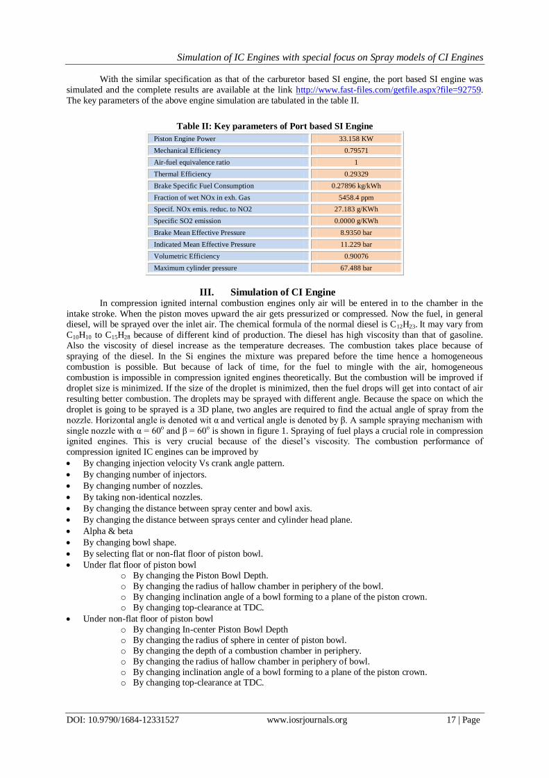
Table II: Key parameters of Port based SI Engine
Piston Engine Power 33.158 KW
Mechanical Efficiency 0.79571
Air-fuel equivalence ratio 1
Thermal Efficiency 0.29329
Brake Specific Fuel Consumption 0.27896 kg/kWh
Fraction of wet NOx in exh. Gas 5458.4 ppm
Specif. NOx emis. reduc. to NO2 27.183 g/KWh
Specific SO2 emission 0.0000 g/KWh
Brake Mean Effective Pressure 8.9350 bar
Indicated Mean Effective Pressure 11.229 bar
Volumetric Efficiency 0.90076
Maximum cylinder pressure 67.488 bar
III. Simulation of CI Engine In compression ignited internal combustion engines only air will be entered in to the chamber in the
intake stroke. When the piston moves upward the air gets pressurized or compressed. Now the fuel, in general diesel, will be sprayed over the inlet air. The chemical formula of the normal diesel is C12H23. It may vary from
C10H10 to C15H28 because of different kind of production. The diesel has high viscosity than that of gasoline.
Also the viscosity of diesel increase as the temperature decreases. The combustion takes place because of
spraying of the diesel. In the Si engines the mixture was prepared before the time hence a homogeneous
combustion is possible. But because of lack of time, for the fuel to mingle with the air, homogeneous
combustion is impossible in compression ignited engines theoretically. But the combustion will be improved if
droplet size is minimized. If the size of the droplet is minimized, then the fuel drops will get into contact of air
resulting better combustion. The droplets may be sprayed with different angle. Because the space on which the
droplet is going to be sprayed is a 3D plane, two angles are required to find the actual angle of spray from the
nozzle. Horizontal angle is denoted wit α and vertical angle is denoted by β. A sample spraying mechanism with
single nozzle with α = 60o and β = 60o is shown in figure 1. Spraying of fuel plays a crucial role in compression ignited engines. This is very crucial because of the diesel’s viscosity. The combustion performance of
compression ignited IC engines can be improved by
By changing injection velocity Vs crank angle pattern.
By changing number of injectors.
By changing number of nozzles.
By taking non-identical nozzles.
By changing the distance between spray center and bowl axis.
By changing the distance between sprays center and cylinder head plane.
Alpha & beta
By changing bowl shape.
By selecting flat or non-flat floor of piston bowl.
Under flat floor of piston bowl
o By changing the Piston Bowl Depth.
o By changing the radius of hallow chamber in periphery of the bowl.
o By changing inclination angle of a bowl forming to a plane of the piston crown.
o By changing top-clearance at TDC.
Under non-flat floor of piston bowl
o By changing In-center Piston Bowl Depth
o By changing the radius of sphere in center of piston bowl.
o By changing the depth of a combustion chamber in periphery.
o By changing the radius of hallow chamber in periphery of bowl.
o By changing inclination angle of a bowl forming to a plane of the piston crown. o By changing top-clearance at TDC.

Simulation of IC Engines with special focus on Spray models of CI Engines
DOI: 10.9790/1684-12331527 www.iosrjournals.org 18 | Page
Fig. 1 Description of angle of spray
As a matter of understanding, different injection velocities are shown in figure 2.
Fig. 2 Different injection velocity Vs Crank angle patterns
The injectors with different distance between spray center and bowl axis are shown in the figure 3. The
injectors with different distance between spray center and cylinder head plane are shown in figure 4. Different
bowl shapes for use in CI engines are shown in figure 5. Different angles of spray are shown in figure 6. Piston
bowls with different Top-clearance at TDC are shown in figure 7. A number of combinations of the above are simulated and the results of three cases are presented in this paper. These cases are
Case I:
Number of nozzles: 1
Bowl shape: Pan
Top-clearance at TDC: 1mm
Distance between spray center and bowl axis: 0 mm
Distance between spray center and cylinder head plane: 0 mm
Injection velocity Vs Crank angle pattern: As shown in first part of figure 2.
Simulation of IC Engines with special focus on Spray models of CI Engines
DOI: 10.9790/1684-12331527 www.iosrjournals.org 19 | Page
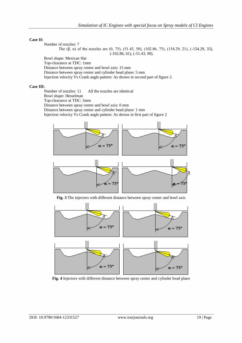
Case II:
Number of nozzles: 7 The (β, α) of the nozzles are (0, 75), (51.43, 50), (102.86, 75), (154.29, 21), (-154.29, 35),
(-102.86, 61), (-51.43, 90).
Bowl shape: Mexican Hat
Top-clearance at TDC: 1mm
Distance between spray center and bowl axis: 15 mm
Distance between spray center and cylinder head plane: 5 mm
Injection velocity Vs Crank angle pattern: As shown in second part of figure 2.
Case III:
Number of nozzles: 11 All the nozzles are identical
Bowl shape: Hesselman Top-clearance at TDC: 5mm
Distance between spray center and bowl axis: 0 mm
Distance between spray center and cylinder head plane: 1 mm
Injection velocity Vs Crank angle pattern: As shown in first part of figure 2
Fig. 3 The injectors with different distance between spray center and bowl axis
Fig. 4 Injectors with different distance between spray center and cylinder head plane

Simulation of IC Engines with special focus on Spray models of CI Engines
DOI: 10.9790/1684-12331527 www.iosrjournals.org 20 | Page
Fig. 5 Different bowl shapes
Fig. 6 Different spray angles
Fig. 7 Piston bowls with different Top-clearance at TDC
The specifications common to all the cases are given below.
Working Cycle: Four Stroke Cycle,
Fuel and Method of Injection: DI Diesel
Number of Cylinders: 1
Cooling System: Liquid Cooling
Cylinder Bore: 150mm, Piston Stroke: 180mm, Nominal Engine Speed: 1400rpm, Compression Ratio: 18,
Cylinder Head Design: Two ports
Simulation of IC Engines with special focus on Spray models of CI Engines
DOI: 10.9790/1684-12331527 www.iosrjournals.org 21 | Page
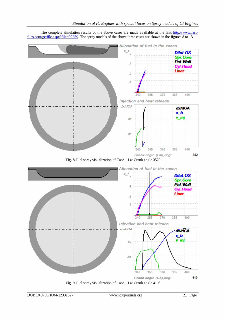
The complete simulation results of the above cases are made available at the link http://www.fast-
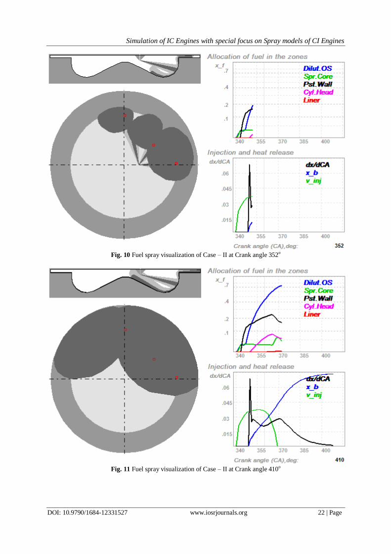
files.com/getfile.aspx?file=92759. The spray models of the above three cases are shown in the figures 8 to 13.
Fig. 8 Fuel spray visualization of Case – I at Crank angle 352o
Fig. 9 Fuel spray visualization of Case – I at Crank angle 410o
Simulation of IC Engines with special focus on Spray models of CI Engines
DOI: 10.9790/1684-12331527 www.iosrjournals.org 22 | Page
Fig. 10 Fuel spray visualization of Case – II at Crank angle 352o
Fig. 11 Fuel spray visualization of Case – II at Crank angle 410o

Simulation of IC Engines with special focus on Spray models of CI Engines
DOI: 10.9790/1684-12331527 www.iosrjournals.org 23 | Page
Fig. 12 Fuel spray visualization of Case – III at Crank angle 352o
Fig. 13 Fuel spray visualization of Case – III at Crank angle 410o

Simulation of IC Engines with special focus on Spray models of CI Engines
DOI: 10.9790/1684-12331527 www.iosrjournals.org 24 | Page
The key parameters of the above engine simulation are tabulated in the table III.
Table III: Key parameters of CI engines simulated
Case – I Case – II Case - III
Piston Engine Power (KW) 24.458 24.377 24.407
Mechanical Efficiency 0.76783 0.76713 0.76614
Air-fuel equivalence ratio 1.7500 1.7500 1.7500
Thermal Efficiency 0.35609 0.35507 0.35576
Brake Specific Fuel Consumption (Kg/KWh) 0.23787 0.23856 0.23810
Fraction of wet NOx in exh. Gas (ppm) 1354.9 1341.4 1504.4
Specif. NOx emis. reduc. to NO2 (g/KWh) 13.651 13.554 15.174
Specific SO2 emission (g/KWh) 0 0 0
Brake Mean Effective Pressure (bar) 6.5908 6.5688 6.5768
Indicated Mean Effective Pressure (bar) 8.5837 8.5628 8.5843
Volumetric Efficiency 0.93193 0.93143 0.93082
Maximum cylinder pressure (bar) 85.401 85.827 89.973
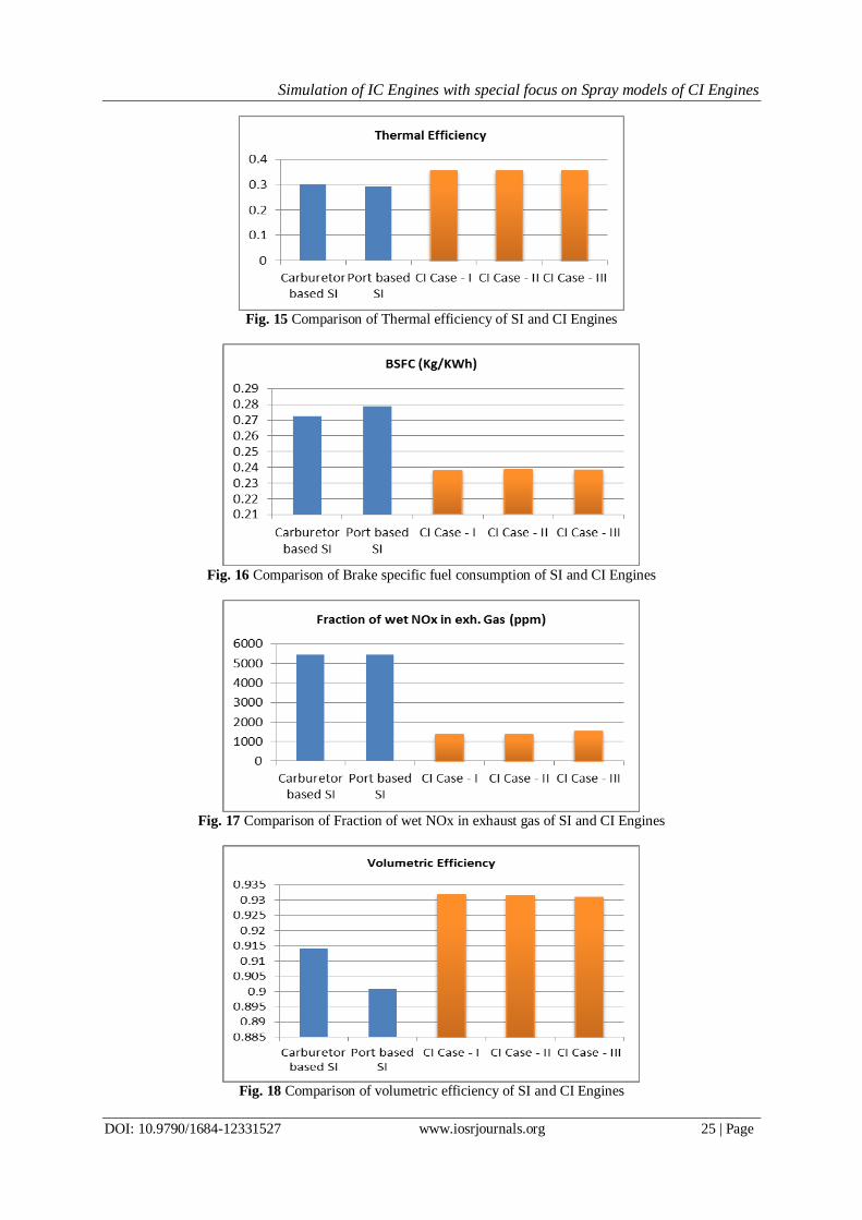
IV. Comparison of SI and CI Engines The figures 14 to 19 show the comparison of different parameters of SI and CI engines. In spark ignited
engines a high volatile fuel gasoline is used and it is mixed with air usually before getting entered into the
chamber. Hence sufficient time is there for the fuel to mix with the air. This results in good combustion. But in
compression ignited engines the fuel is diesel which has high viscosity and this viscosity tends to rise when
temperature decreases. The fuel is sprayed on the compressed fuel and there is very little time for the fuel to get
mingled with air. Also because the diesel has high viscosity the fuel will have less interaction with air and
results in poor combustion. The compression ratio in spark ignited engines is in the range of 6 to 10; where as in compression ignited engines it is in the range of 16 to 20.
Hence more air molecules are available in the case of CI engines. These air molecules help to reduce
the NOx emissions. Because in CI engines more than enough air proportion is available for the nitrogen
molecules to become nitrogen dioxide, but in SI engines due to the lack of air molecules the nitrogen may form
NOx which is harm to the ecosystem. This can be verified from figure 17. From figure 19 it can be observed that
the maximum pressure of the cylinder is high in CI engines than that of SI engines, correspondingly the weight
and size of the CI engines will be high compared to that of SI engines. It also leads to the requirement of high
work to drive the self-weight also. Due to less weight the speed attainable by the SI engines is high. From the
figure 15 it can be observed that the thermal efficiency of SI engines is less compared to that of CI engines. This
is because the compression ratio of SI engines is less.
Fig. 14 Comparison of Piston engine power of SI and CI Engines
Simulation of IC Engines with special focus on Spray models of CI Engines
DOI: 10.9790/1684-12331527 www.iosrjournals.org 25 | Page
Fig. 15 Comparison of Thermal efficiency of SI and CI Engines
Fig. 16 Comparison of Brake specific fuel consumption of SI and CI Engines
Fig. 17 Comparison of Fraction of wet NOx in exhaust gas of SI and CI Engines
Fig. 18 Comparison of volumetric efficiency of SI and CI Engines

Simulation of IC Engines with special focus on Spray models of CI Engines
DOI: 10.9790/1684-12331527 www.iosrjournals.org 26 | Page
Fig. 19 Comparison of maximum cylinder pressure of SI and CI Engines
V. Conclusions In this paper a comprehensive modeling of both SI and CI engines was presented. The carburetor based
and port based engines are considered in SI category. Three cases of CI engines are considered. In each- case
different spraying characteristics, different injection velocity patterns and different bowl characteristics are
taken. The SI and CI engines are compared based on performance metrics like piston engine power, specific fuel
consumption, NOx levels, and cylinder pressure, thermal and volumetric efficiency. The advantages and limitations of SI and CI engines are elaborated. It might be questioned to devise an engine with the advantages
of both SI and CI engines. There are three alternative for this. One by adding diesel fuel with air ahead of time
or indirectly, sufficient time must be provided for the diesel fuel to mix with air. Second, the gasoline fuel may
be sprayed on the compressed air. The last, the gasoline may be mixed with air before the time and then by
compressing it as in the case of CI engine. The possibilities and implementations of the above three alternatives
are the current state of art in the IC engine development.
References [1] Durst, F., Weclas, M., Method and device for converting heat into work, US Patent No.6, 125,815 (2000).
[2] Yang, H., Shuai, S., Wang, Z., and Wang, J., ―High Efficiency and Low Pollutants Combustion: Gasoline Multiple Premixed
Compression Ignition (MPCI),‖ SAE Technical Paper 2012-01-0382, 2012, doi:10.4271/2012-01-0382.
[3] Y. Iwamoto, K. Noma, O. Nakayama, T. Yamauchi and H. Ando, ―Development of Gasoline Direct Injection Engine‖, Mitsubishi
Motors Co., SAE Technical Paper 970541, 1997.
[4] Woo Tae Kim, Huh K.Y., ―Supercomputing applications in internal combustion engine design and analysis‖, HPC Asia '97 High
Performance Computing on the Information Superhighway, 1997.
[5] Xiaojian Yang, Guoming Zhu, ―SI and HCCI Combustion Mode Transition Control of an HCCI Capable SI Engine‖, IEEE
Transactions on Control Systems Technology, Vol.21, Issue 5, June 2012.
[6] Abdul Jalal R.I, Steffen T, Williams A., ―SI engine combustion wall thermal management potential without the presence of control
limitation‖, 2014 UKACC International Conference on Control, July 2014.
[7] H. T. Aichlmayr, D. B. Kittelson, M. R. Zachariah, ―Miniature free-piston homogeneous charge compression ignition engine-
compressor concept—Part I: performance estimation and design considerations unique to small dimensions‖, ELSEVIER Chemical
Engineering Science 57 (2002) 4161–4171.
[8] Olivier Grondin, Richard Stobart, Houcine Chafouk, Jean Maquet, ―Modeling the Compression Ignition Engine for Control: Review
and Future Trends‖, Society of Automotive Engineers, Inc., 2004-01-0423.
[9] John E. Dec, ―Advanced compression-ignition engines—understanding the in-cylinder processes‖, Proceedings of the Combustion
Institute ELSEVIER, 32 (2009) 2727–2742.
[10] M. Basinger, T. Reding, C. Williams, K. S. Lackner, V. Modi, ―Compression Ignition Engine Modifications for Straight Plant Oil
Fueling in Remote Contexts: Modification Design and Short-run Testing‖, Fuel 2009.
[11] Marcin Noga, Bronislaw Sendyka, ―New Design of the Five-Stroke SI Engine‖, Journal of KONES Powertrain and Transport, Vol.
20, No. 1 2013.
[12] Meisam Ahmadi Ghadikolaei, ―History of Gasoline Direct Compression Ignition (GDCI) Engine- A Review‖, IJRET: International
Journal of Research in Engineering and Technology, Vol. 3 Issue 01, Jan-2014.
[13] Paljoo Yoon, Seungbum Park, Myoungho Sunwoo, ―A Nonlinear Dynamic Model of SI Engines for Designing Controller‖, Seoul
2000 FISITA World Automotive Congress, June 12-15, 2000, Seoul, Korea.
[14] Karol Cupiał, Arkadiusz Jamrozik, ―SI Engine with the Sectional Combustion Chamber‖, Journal of KONES Internal Combustion
Engines 2002 No. 3‐4.

Simulation of IC Engines with special focus on Spray models of CI Engines
DOI: 10.9790/1684-12331527 www.iosrjournals.org 27 | Page
Author’s Profile
Suresh Muchakala received B.E in Mechanical engineering from AMACE, University of Madras,
Kanchipuram in 1999 and M.Tech in Thermal Engineering from Jawaharlal Nehru
Technological University, Hyderabad in 2005. Currently he is doing Ph.D on DISI Engines
in Jawaharlal Nehru Technological University Anatapur. Since 2001, he held many positions
like Asst. Prof., Asso. Prof., Examination Section In charge and currently he is working as
the Head of the Department of Mechanical Engineering, all in GKCE, Sullurpet. His research interests include Thermal Engineering, CFD Solutions and IC Engines.
Dr.R.HariPrakash received B.Tech & M.Tech with distinction from Birla Institute of Technology Ranchi. He
Obtained PhD from Indian Institute of Technology, Madras. He has 35 years of
Industry/Research/Teaching at various levels. He worked as senior lecturer at Nanyang
University, Singapore. He worked in NBKR Institute of Science & Technology Vidyanagar as
Assistant professor and became Professor and Head of the Department. He is a Member of
Board of Studies at JNTU Anantapur, S.V. University, Anna University, and Vellore Institute
of Technology. He has published seven papers in National & four papers in International
Journals. He worked as Principal of Gokula Krishna College of Engineering, Sullurpet, and Sri
Venkateswara College of Engineering, Chittoor, Brahmaiah College of Engineering, Nellore, and Dr. K. V. Subba Reddy College of Engineering, Dupadu, Kurnool DT, currently he is working as Principal of Jagan’s
College of Engineering & Technology, Choutapalem, Nellore. He has authored the book ―Operations Research‖
published by SCITECH publishers, Hyderabad. He is a Member of Indian Society for Technical Education,
Indian Society for Non-Destructive Testing, Indian society for Automobile Engineering and American society
of Mechanical Engineering, Fellow of Institute of Engineers. His areas of research specialization are Energy
Management, Energy Distribution, Alternate source of Energy, Ecofuels.
Dr. B. Durga Prasad received B.Tech, M.Tech and Ph.D from the Department of Mechanical Engineering,
JNTU Anantapur. Currently he is working as Professor and Head in the Department of
Mechanical Engineering, JNTUA, Anantapuramu. He has more than 22 years of teaching
experience He has published about 50 research papers in national and international journals and about another 40 research papers in national and international conferences. His research
area includes Internal Combustion engines, Thermal Engineering, Alternate Fuels and Non-
conventional Energy Resources.