simulation and validation in vhld test bench - unsjdea.unsj.edu.ar/cursos/10.pdf · architecture...
TRANSCRIPT
Simulation and Validation in VHLDSimulation and Validation in VHLD
© Cristian Sisterna 1
Test Bench Test Bench

Test Bench Test Bench -- OverviewOverview
We have concentrated on VHDL for
synthesis so far
VHDL is also used as a Test Language
Very important to conduct comprehensive
verification on your design
To simulate a design you need to produce
an additional entity and architecture pair
© Cristian Sisterna 2
Test Bench Test Bench -- OverviewOverview
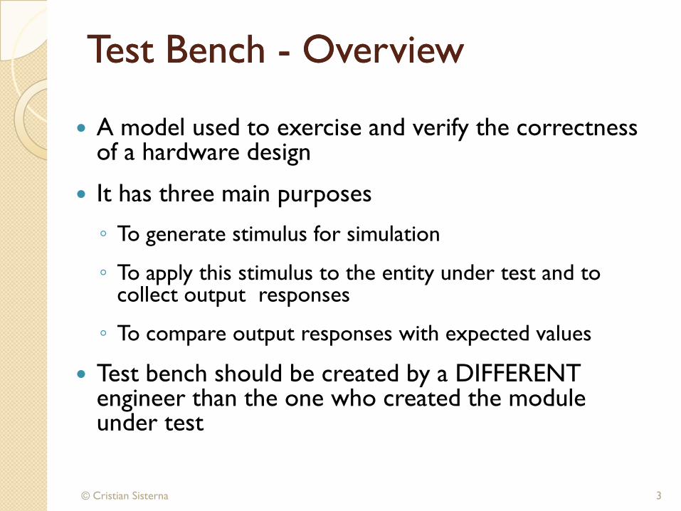
A model used to exercise and verify the correctness of a hardware design
It has three main purposes
◦ To generate stimulus for simulation
◦ To apply this stimulus to the entity under test and to collect output responses
◦ To compare output responses with expected values
Test bench should be created by a DIFFERENT engineer than the one who created the module under test
© Cristian Sisterna 3
© Cristian Sisterna
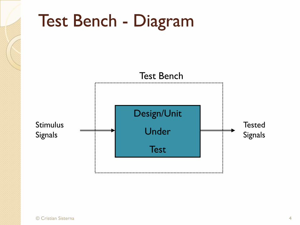
Test Bench Test Bench -- DiagramDiagram
4
Design/Unit
Under
Test
Test Bench
Stimulus
Signals
Tested
Signals
© Cristian Sisterna
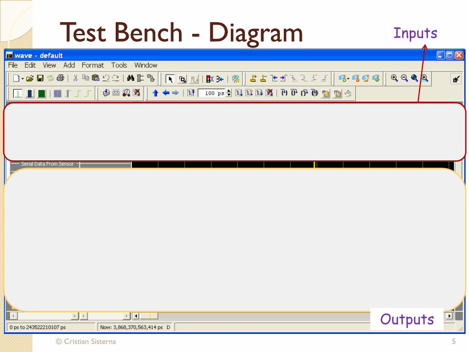
Test Bench Test Bench -- DiagramDiagram
5
Design/Unit
Under
Test
Test Bench
Stimulus
Signals
Tested
Signals
Inputs
Outputs
© Cristian Sisterna
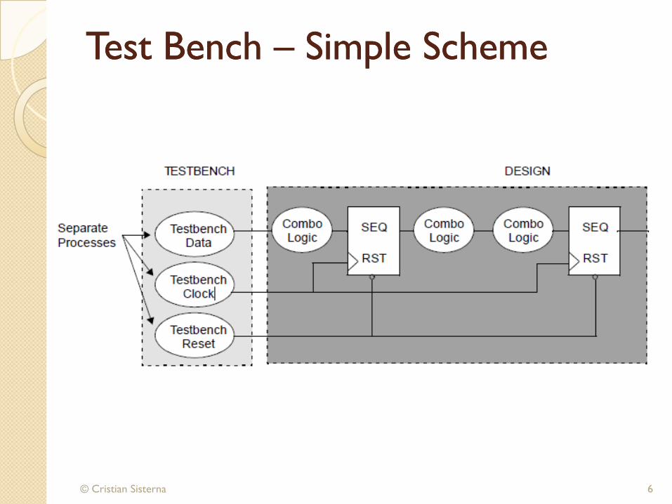
Test Bench Test Bench –– Simple Scheme Simple Scheme
6
Design/Unit)
Under
Test
Stimulus
Signals
Tested
Signals

Test Bench Test Bench -- ComponentsComponents
© Cristian Sisterna 7
TB entity (empty) declaration
TB architecture declaration
Component declaration
Local signal declaration
Component instantiation
Stimulus statements
Check values statements
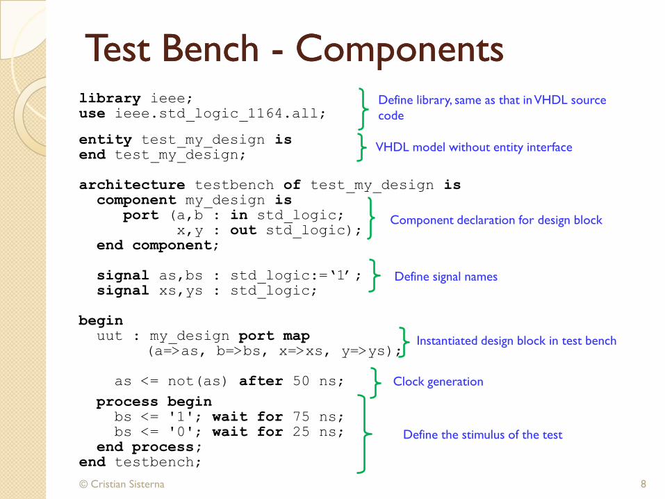
Test Bench Test Bench -- Components Components
© Cristian Sisterna 8
library ieee;use ieee.std_logic_1164.all;
entity test_my_design isend test_my_design;
architecture testbench of test_my_design iscomponent my_design is
port (a,b : in std_logic;
x,y : out std_logic);
end component;
signal as,bs : std_logic:=„1‟;
signal xs,ys : std_logic;
begin uut : my_design port map
(a=>as, b=>bs, x=>xs, y=>ys);
as <= not(as) after 50 ns;
process beginbs <= '1'; wait for 75 ns;bs <= '0'; wait for 25 ns;
end process;end testbench;
Define library, same as that in VHDL source
code
VHDL model without entity interface
Component declaration for design block
Define signal names
Instantiated design block in test bench
Define the stimulus of the test
Clock generation
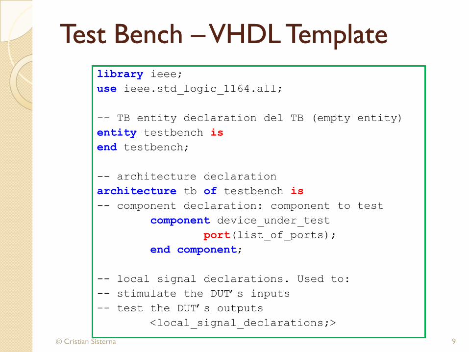
Test Bench Test Bench ––VHDL TemplateVHDL Template
© Cristian Sisterna 9
library ieee;
use ieee.std_logic_1164.all;
-- TB entity declaration del TB (empty entity)
entity testbench is
end testbench;
-- architecture declaration
architecture tb of testbench is
-- component declaration: component to test
component device_under_test
port(list_of_ports);
end component;
-- local signal declarations. Used to:
-- stimulate the DUT‟s inputs
-- test the DUT‟s outputs
<local_signal_declarations;>
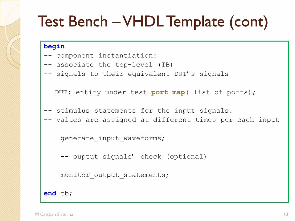
Test Bench Test Bench ––VHDL Template (cont)VHDL Template (cont)
© Cristian Sisterna 10
begin
-- component instantiation:
-- associate the top-level (TB)
-- signals to their equivalent DUT‟s signals
DUT: entity_under_test port map( list_of_ports);
-- stimulus statements for the input signals.
-- values are assigned at different times per each input
generate_input_waveforms;
-- ouptut signals‟ check (optional)
monitor_output_statements;
end tb;
Test Bench Test Bench –– Use of Use of waitwait
© Cristian Sisterna 11
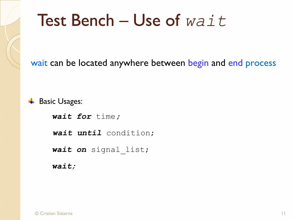
wait can be located anywhere between begin and end process
Basic Usages:
wait for time;
wait until condition;
wait on signal_list;
wait;

Test Bench Test Bench –– Use of Use of waitwait
© Cristian Sisterna 12
process
. . .
J <= „1‟;
wait for 50 ns; -- process is suspend for 50 ns after J is . . . -- assigned to ‘1’
end process;
Examples
process
. . .
wait until CLK = „1‟;-- sync with CLK rising edge before
-- continuing of simulation. . .
end process;
Test Bench Test Bench –– Use of Use of waitwait
© Cristian Sisterna 13
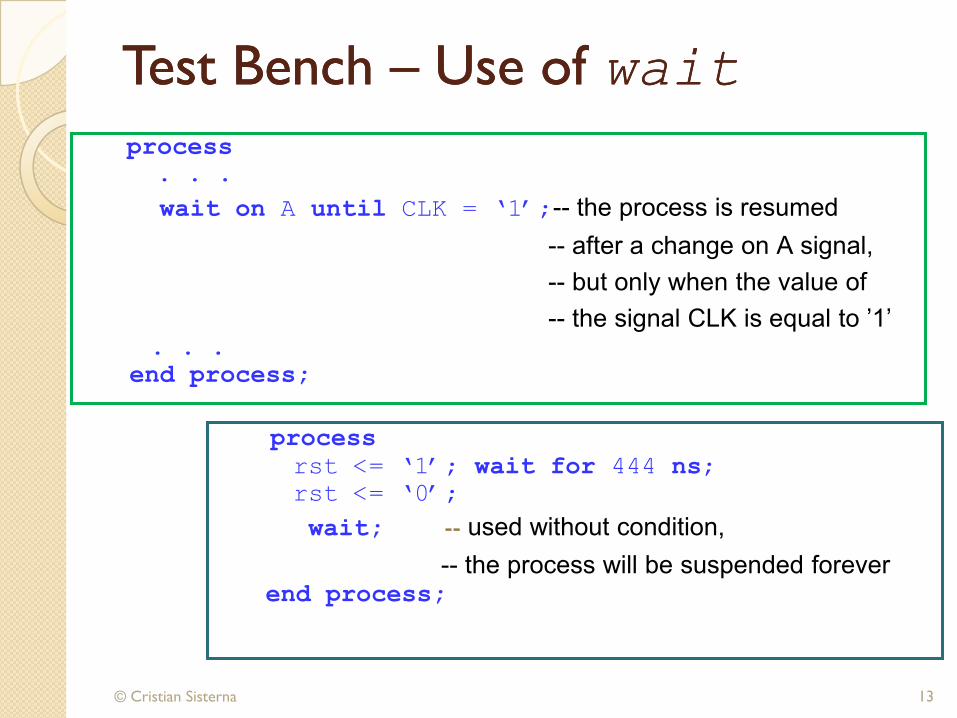
process
. . .
wait on A until CLK = „1‟;-- the process is resumed
-- after a change on A signal,
-- but only when the value of
-- the signal CLK is equal to ’1’. . .
end process;
process
rst <= „1‟; wait for 444 ns;
rst <= „0‟;
wait; -- used without condition,
-- the process will be suspended foreverend process;
Test Bench Test Bench –– Clock GenerationClock Generation
© Cristian Sisterna 14
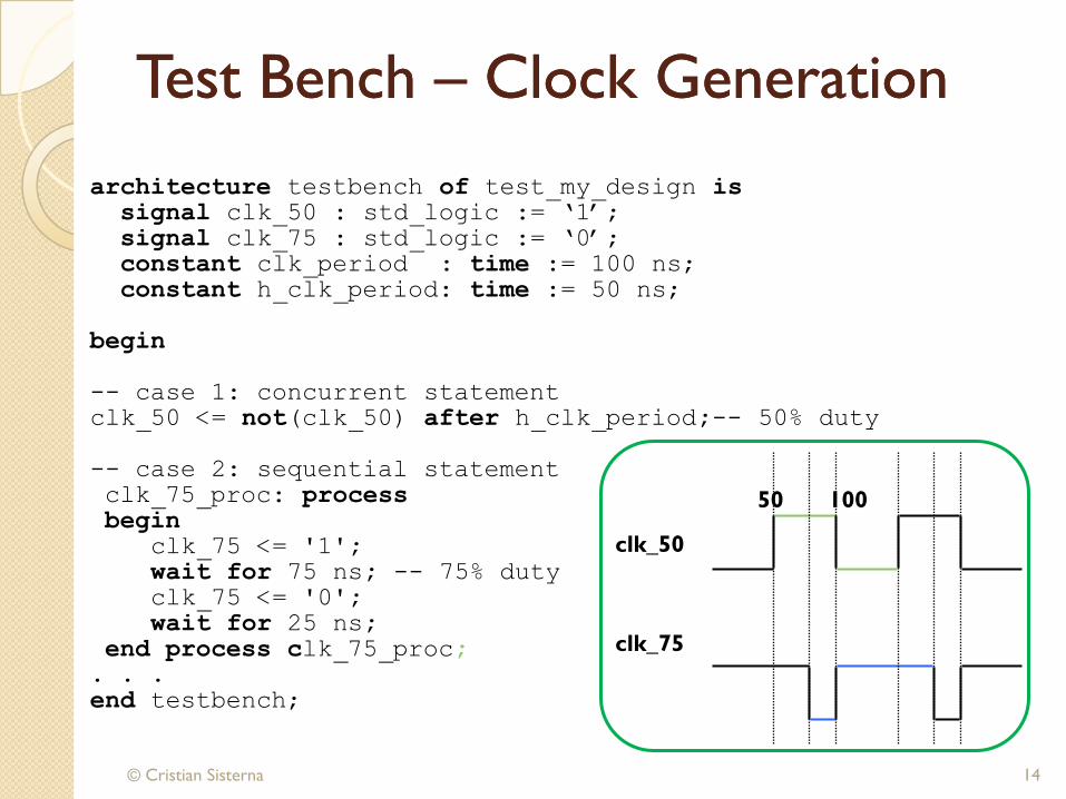
architecture testbench of test_my_design issignal clk_50 : std_logic := „1‟;
signal clk_75 : std_logic := „0‟;
constant clk_period : time := 100 ns;
constant h_clk_period: time := 50 ns;
begin
-- case 1: concurrent statement
clk_50 <= not(clk_50) after h_clk_period;-- 50% duty
-- case 2: sequential statement
clk_75_proc: process begin
clk_75 <= '1'; wait for 75 ns; -- 75% duty
clk_75 <= '0'; wait for 25 ns;
end process clk_75_proc;. . .
end testbench;
clk_50
50 100
clk_75

Test Bench Test Bench –– Clock GenerationClock Generation
© Cristian Sisterna 15
architecture testbench of test_my_design is
signal clk: std_logic := „0‟;
constant period: time := 40 ns;
begin
diff_duty_clk_cycle: process
begin
clk <= „0‟;
wait for period * 0.60;
clk <= „1‟;
wait for period * 0.40; -- 60% duty cycle
end process diff_duty_clk_cycle;
. . .
end architecture testbench;
Clock generation example of duty cycle diff. of 50%
Test Bench Test Bench –– Clock GenerationClock Generation
© Cristian Sisterna 16
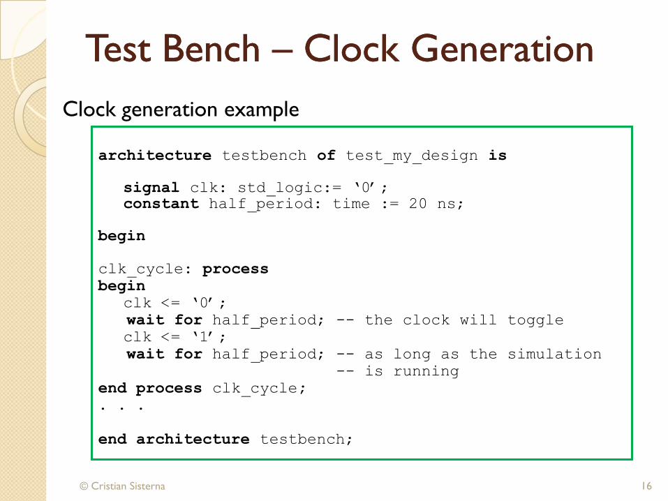
architecture testbench of test_my_design is
signal clk: std_logic:= „0‟;
constant half_period: time := 20 ns;
begin
clk_cycle: process
begin
clk <= „0‟;
wait for half_period; -- the clock will toggle
clk <= „1‟;
wait for half_period; -- as long as the simulation
-- is running
end process clk_cycle;
. . .
end architecture testbench;
Clock generation example
Test Bench Test Bench –– Data GenerationData Generation
Avoid race conditions between data and clock
Applying the data and the active edge of the clock
simultaneously might cause a race condition
© Cristian Sisterna 17
To keep data synchronized with the clock while avoiding
race condition, apply the data at a different point in the
clock period that at the active edge of clock
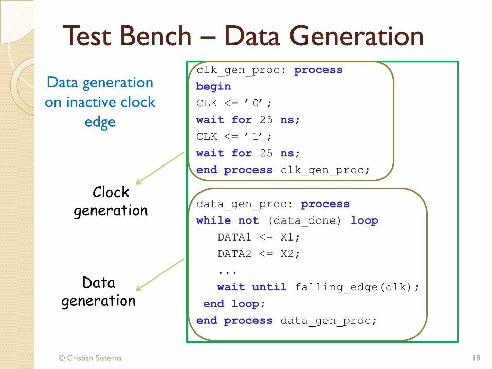
Test Bench Test Bench –– Data GenerationData Generationclk_gen_proc: process
begin
CLK <= ‟0‟;
wait for 25 ns;
CLK <= ‟1‟;
wait for 25 ns;
end process clk_gen_proc;
data_gen_proc: process
while not (data_done) loop
DATA1 <= X1;
DATA2 <= X2;
...
wait until falling_edge(clk);
end loop;
end process data_gen_proc;
© Cristian Sisterna 18
Data generation
on inactive clock
edge
Clock generation
Data generation

Test Bench Test Bench –– Data GenerationData Generation
© Cristian Sisterna 19
architecture relative_timing of myTest is
signal Add_Bus: std_logic_vector(7 downto 0);
begin
patt_gen_proc: processbegin
Add_Bus <= “00000000”;
wait for 10 ns;
Add_Bus <= “00000101”;
wait for 10 ns;
Add_Bus <= “10101010”;
wait for 10 ns;
end process patt_gen_proc;. . .end relative_timing;
00000000 00000101
10 20 30
10101010 00000000
Relative time: signal waveforms that are specified to change at simulation
times relative to the previous time, in a time accumulated manner

Test Bench Test Bench –– Data GenerationData Generation
© Cristian Sisterna 20
architecture absolute_timing of testbench is
signal A_BUS : std_logic_vector(7 downto 0);
beginA_BUS <= “00000000”,
“00000101” after 10 ns,
“00001010” after 20 ns;
-- etc.
. . .
end absolute_timing;00000101 00001010
10 20 30
00000000
Absolute time: signal waveforms that are specified to change at
simulation times absolute since the moment that the simulation begin
Test Bench Test Bench –– Data GenerationData Generation
© Cristian Sisterna 21
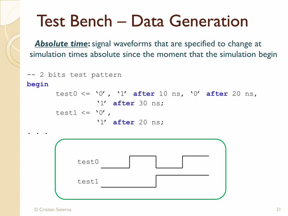
-- 2 bits test pattern
begin
test0 <= „0‟, „1‟ after 10 ns, „0‟ after 20 ns,
„1‟ after 30 ns;
test1 <= „0‟,
„1‟ after 20 ns;
. . .
test0
test1
Absolute time: signal waveforms that are specified to change at
simulation times absolute since the moment that the simulation begin
Test Bench Test Bench –– Data GenerationData Generation
© Cristian Sisterna 22
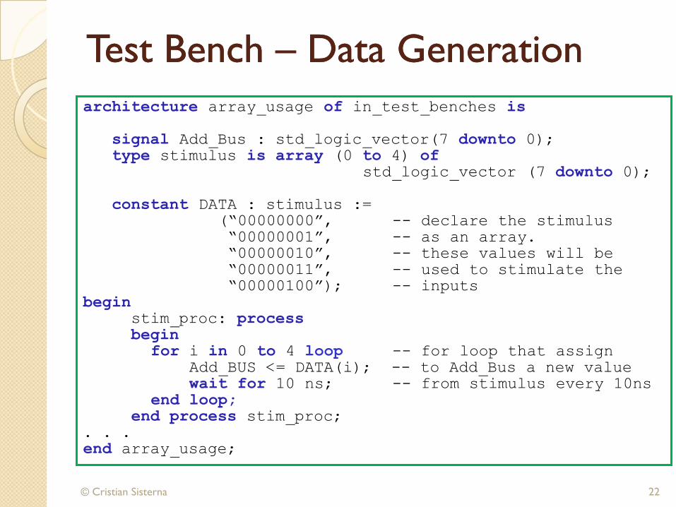
architecture array_usage of in_test_benches is
signal Add_Bus : std_logic_vector(7 downto 0);
type stimulus is array (0 to 4) ofstd_logic_vector (7 downto 0);
constant DATA : stimulus :=
(“00000000”, -- declare the stimulus
“00000001”, -- as an array.
“00000010”, -- these values will be
“00000011”, -- used to stimulate the
“00000100”); -- inputs
beginstim_proc: processbegin
for i in 0 to 4 loop -- for loop that assign
Add_BUS <= DATA(i); -- to Add_Bus a new value
wait for 10 ns; -- from stimulus every 10ns
end loop;end process stim_proc;
. . .
end array_usage;
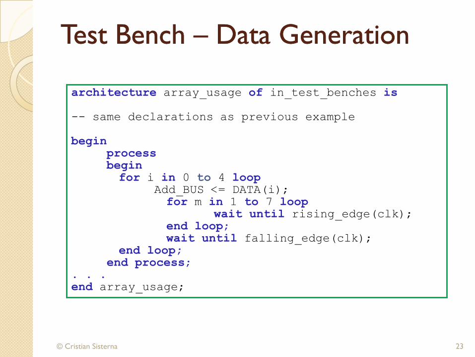
Test Bench Test Bench –– Data GenerationData Generation
© Cristian Sisterna 23
architecture array_usage of in_test_benches is
-- same declarations as previous example
beginprocessbeginfor i in 0 to 4 loop
Add_BUS <= DATA(i);
for m in 1 to 7 loopwait until rising_edge(clk);
end loop;wait until falling_edge(clk);
end loop;end process;
. . .
end array_usage;
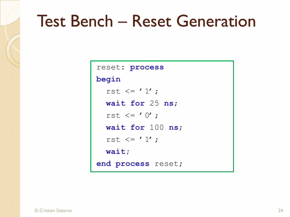
Test Bench Test Bench –– Reset Generation Reset Generation
reset: process
begin
rst <= ‟1‟;
wait for 25 ns;
rst <= ‟0‟;
wait for 100 ns;
rst <= ‟1‟;
wait;
end process reset;
© Cristian Sisterna 24
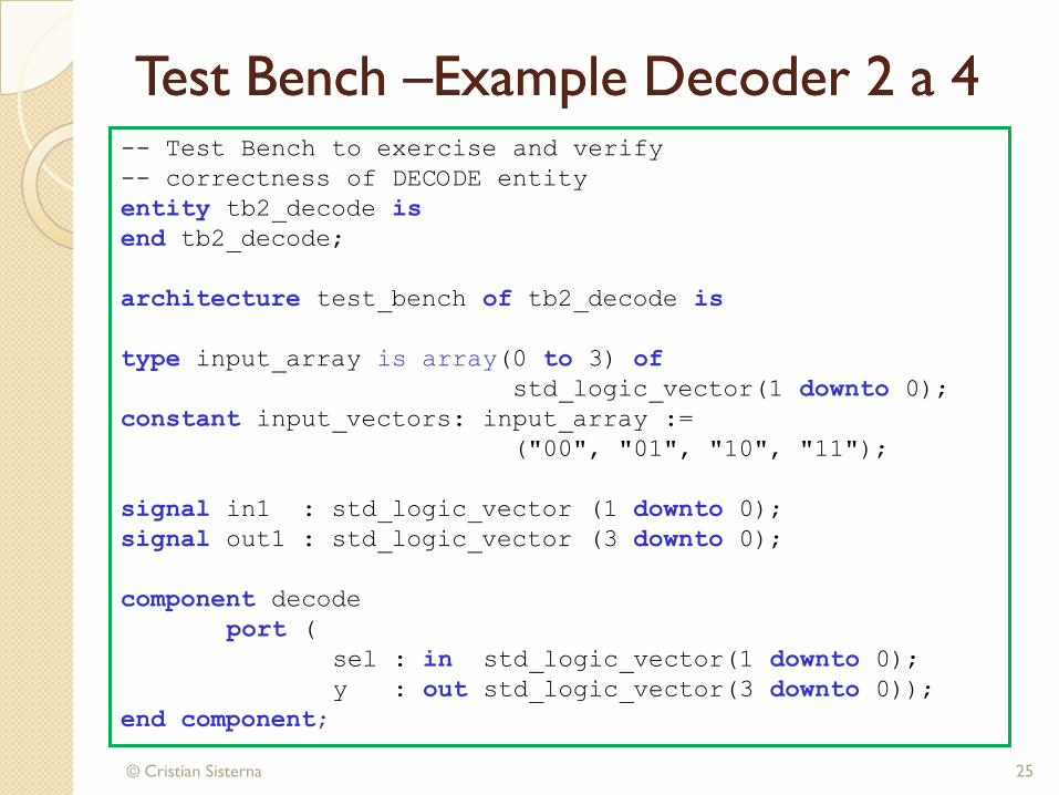
Test Bench Test Bench ––Example Decoder 2 a 4Example Decoder 2 a 4
© Cristian Sisterna 25
-- Test Bench to exercise and verify
-- correctness of DECODE entity
entity tb2_decode is
end tb2_decode;
architecture test_bench of tb2_decode is
type input_array is array(0 to 3) of
std_logic_vector(1 downto 0);
constant input_vectors: input_array :=
("00", "01", "10", "11");
signal in1 : std_logic_vector (1 downto 0);
signal out1 : std_logic_vector (3 downto 0);
component decode
port (
sel : in std_logic_vector(1 downto 0);
y : out std_logic_vector(3 downto 0));
end component;
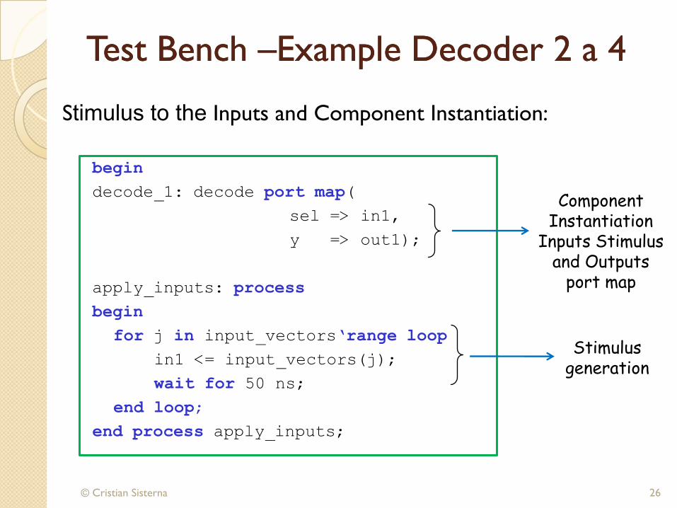
Test Bench Test Bench ––Example Decoder 2 a 4Example Decoder 2 a 4
begin
decode_1: decode port map(
sel => in1,
y => out1);
apply_inputs: process
begin
for j in input_vectors„range loop
in1 <= input_vectors(j);
wait for 50 ns;
end loop;
end process apply_inputs;
© Cristian Sisterna 26
Component Instantiation
Inputs Stimulus and Outputs
port map
Stimulus generation
Stimulus to the Inputs and Component Instantiation:

Test BenchTest Bench––Example Decoder 2 to 4Example Decoder 2 to 4
test_outputs: process
begin
wait until (in1 = "01");
wait for 25 ns;
assert (out1 = "0110")
report"Output not equal to 0110"
severity ERROR;
end process test_outputs;
© Cristian Sisterna 27
Input stimulus
Wait on certain time
Check the output
Output’s check
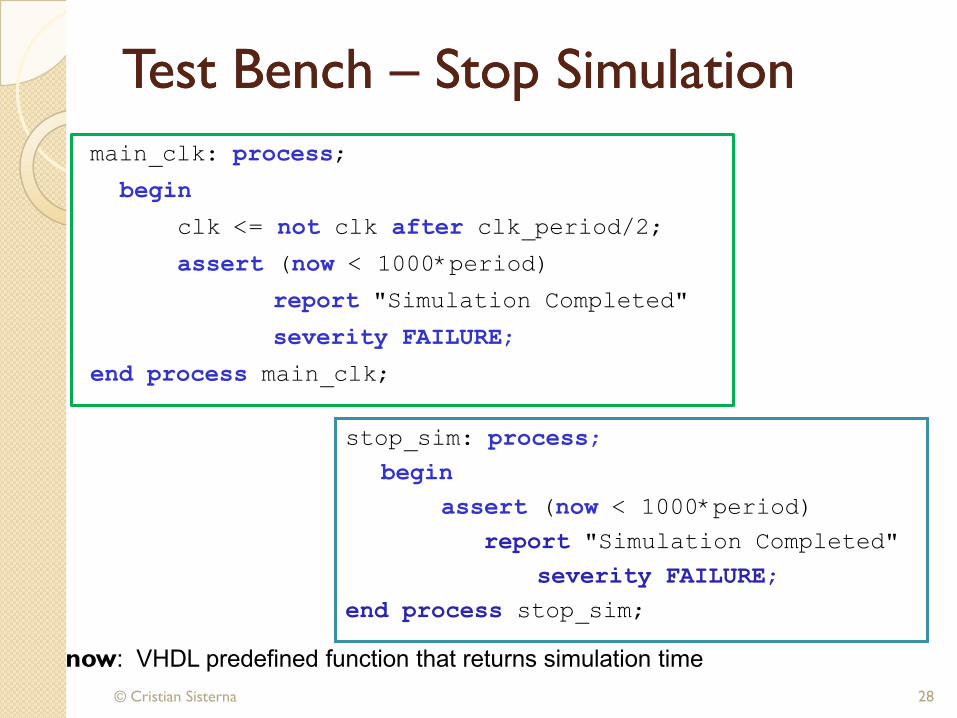
Test Bench Test Bench –– Stop SimulationStop Simulation
main_clk: process;
begin
clk <= not clk after clk_period/2;
assert (now < 1000*period)
report "Simulation Completed"
severity FAILURE;
end process main_clk;
© Cristian Sisterna 28
now: VHDL predefined function that returns simulation time
stop_sim: process;
begin
assert (now < 1000*period)
report "Simulation Completed"
severity FAILURE;
end process stop_sim;
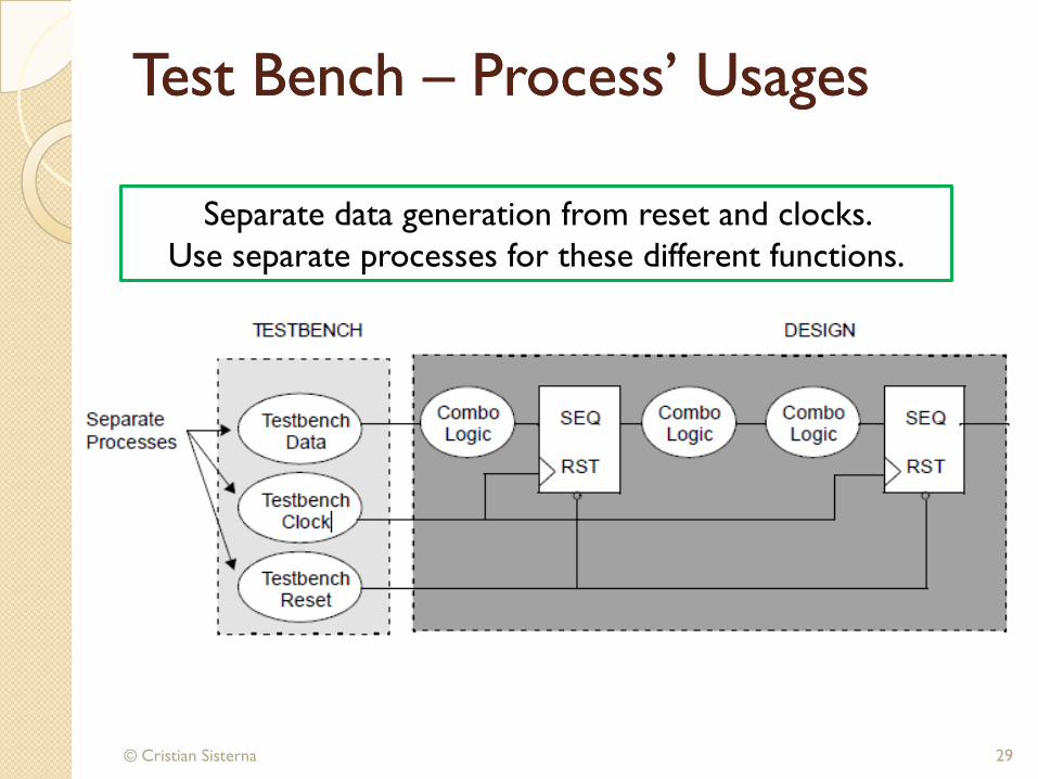
Test Bench Test Bench –– Process’ UsagesProcess’ Usages
© Cristian Sisterna 29
Separate data generation from reset and clocks.
Use separate processes for these different functions.
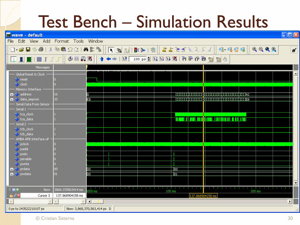
Test Bench Test Bench –– Simulation ResultsSimulation Results
© Cristian Sisterna 30

Test Bench Test Bench –– Simulation ResultsSimulation Results
© Cristian Sisterna 31

Test Bench Test Bench –– Example 74LS194Example 74LS194
© Cristian Sisterna 32
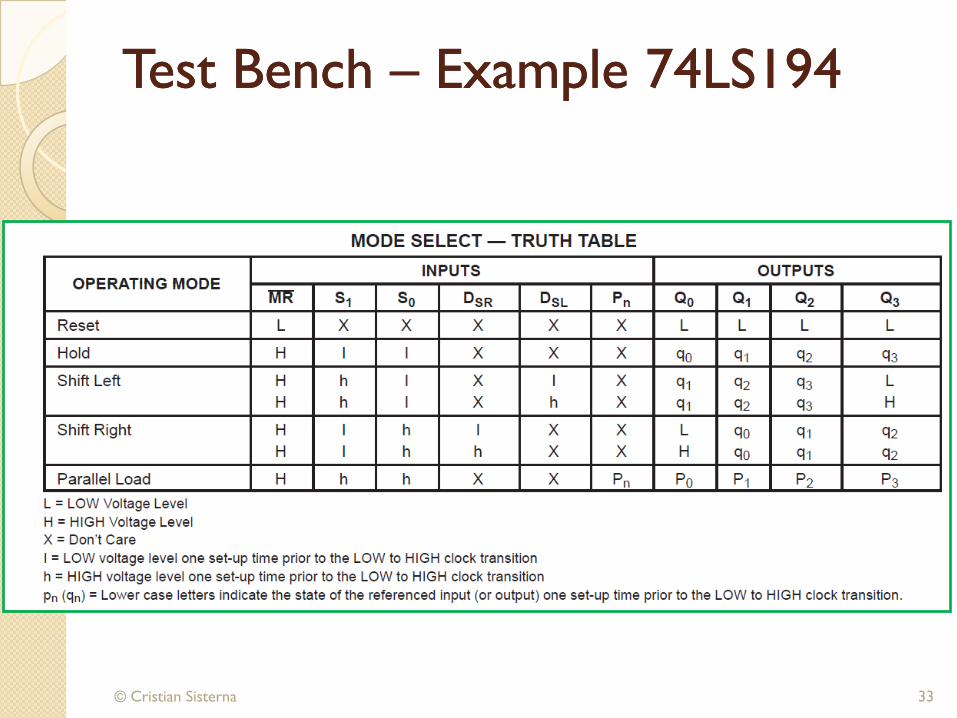
Test Bench Test Bench –– Example 74LS194Example 74LS194
© Cristian Sisterna 33
Test Bench Test Bench –– Example 74LS194 (1)Example 74LS194 (1)
© Cristian Sisterna 34
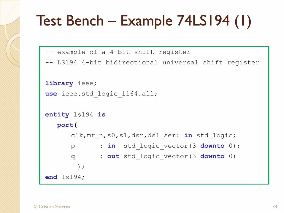
-- example of a 4-bit shift register
-- LS194 4-bit bidirectional universal shift register
library ieee;
use ieee.std_logic_1164.all;
entity ls194 is
port(
clk,mr_n,s0,s1,dsr,dsl_ser: in std_logic;
p : in std_logic_vector(3 downto 0);
q : out std_logic_vector(3 downto 0)
);
end ls194;
Test Bench Test Bench –– Example 74LS194 (2)Example 74LS194 (2)
© Cristian Sisterna 35
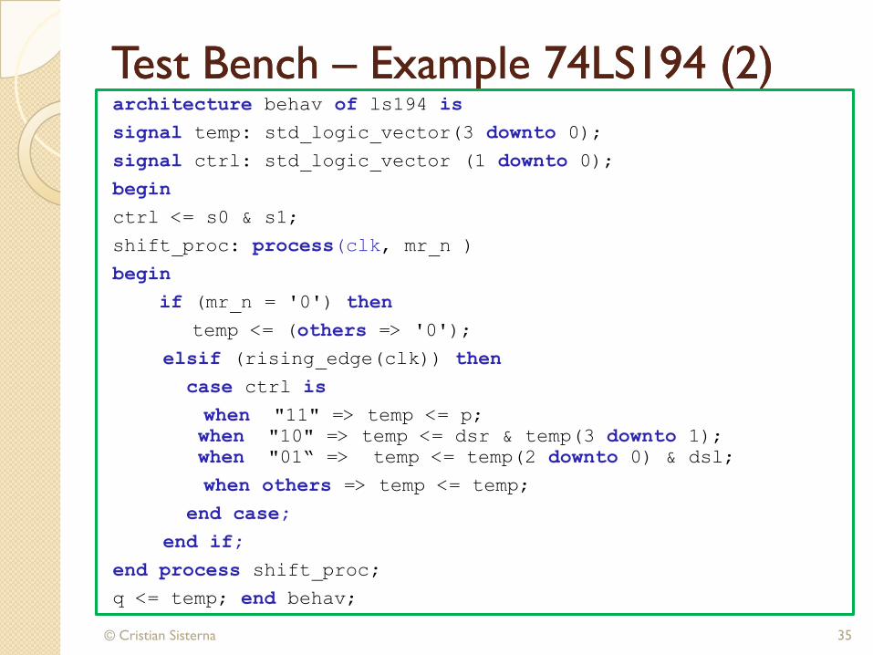
architecture behav of ls194 is
signal temp: std_logic_vector(3 downto 0);
signal ctrl: std_logic_vector (1 downto 0);
begin
ctrl <= s0 & s1;
shift_proc: process(clk, mr_n )
begin
if (mr_n = '0') then
temp <= (others => '0');
elsif (rising_edge(clk)) then
case ctrl is
when "11" => temp <= p;
when "10" => temp <= dsr & temp(3 downto 1);
when "01“ => temp <= temp(2 downto 0) & dsl;
when others => temp <= temp;
end case;
end if;
end process shift_proc;
q <= temp; end behav;
Test Bench Test Bench –– Example 74LS194 (3)Example 74LS194 (3)
© Cristian Sisterna 36
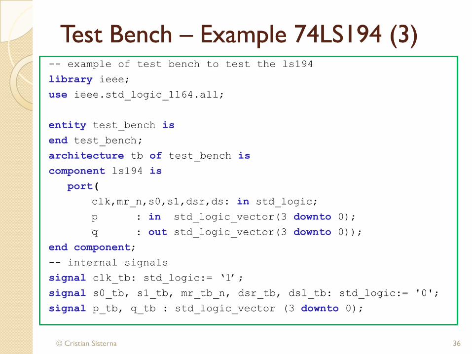
-- example of test bench to test the ls194
library ieee;
use ieee.std_logic_1164.all;
entity test_bench is
end test_bench;
architecture tb of test_bench is
component ls194 is
port(
clk,mr_n,s0,s1,dsr,ds: in std_logic;
p : in std_logic_vector(3 downto 0);
q : out std_logic_vector(3 downto 0));
end component;
-- internal signals
signal clk_tb: std_logic:= „1‟;
signal s0_tb, s1_tb, mr_tb_n, dsr_tb, dsl_tb: std_logic:= '0';
signal p_tb, q_tb : std_logic_vector (3 downto 0);
Test Bench Test Bench –– Example 74LS194 (4)Example 74LS194 (4)
© Cristian Sisterna 37
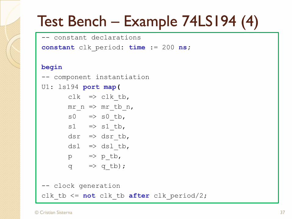
-- constant declarations
constant clk_period: time := 200 ns;
begin
-- component instantiation
U1: ls194 port map(
clk => clk_tb,
mr_n => mr_tb_n,
s0 => s0_tb,
s1 => s1_tb,
dsr => dsr_tb,
dsl => dsl_tb,
p => p_tb,
q => q_tb);
-- clock generation
clk_tb <= not clk_tb after clk_period/2;
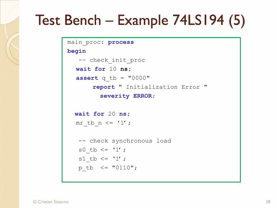
Test Bench Test Bench –– Example 74LS194 (5)Example 74LS194 (5)
© Cristian Sisterna 38
main_proc: process
begin
-- check_init_proc
wait for 10 ns;
assert q_tb = "0000"
report " Initialization Error "
severity ERROR;
wait for 20 ns;
mr_tb_n <= '1‟;
-- check synchronous load
s0_tb <= „1‟;
s1_tb <= „1‟;
p_tb <= "0110";
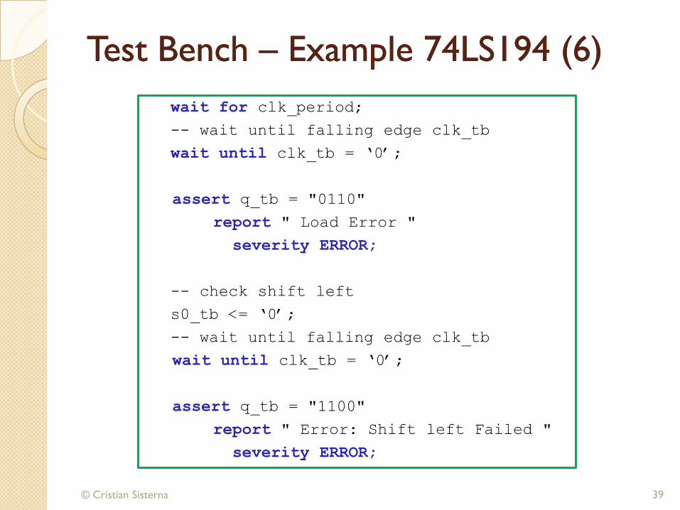
Test Bench Test Bench –– Example 74LS194 (6)Example 74LS194 (6)
© Cristian Sisterna 39
wait for clk_period;
-- wait until falling edge clk_tb
wait until clk_tb = „0‟;
assert q_tb = "0110"
report " Load Error "
severity ERROR;
-- check shift left
s0_tb <= „0‟;
-- wait until falling edge clk_tb
wait until clk_tb = „0‟;
assert q_tb = "1100"
report " Error: Shift left Failed "
severity ERROR;
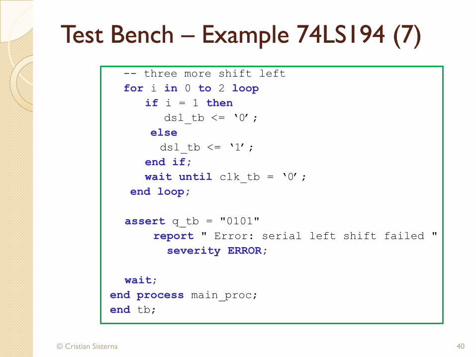
Test Bench Test Bench –– Example 74LS194 (7)Example 74LS194 (7)
© Cristian Sisterna 40
-- three more shift left
for i in 0 to 2 loop
if i = 1 then
dsl_tb <= „0‟;
else
dsl_tb <= „1‟;
end if;
wait until clk_tb = „0‟;
end loop;
assert q_tb = "0101"
report " Error: serial left shift failed "
severity ERROR;
wait;
end process main_proc;
end tb;

Test Bench Test Bench –– Example 74LS194 (8)Example 74LS194 (8)
© Cristian Sisterna 41
Test Bench Test Bench -- ConclusionConclusion
© Cristian Sisterna 42
TB is done in VHDL code
Emulate the Hardware
Use all the power of VHLD
There is no size limit
TB is the top-level unit
Usually is more complex than the design itself